EP1982791A2 - Manufacturing method for a hollow fan blade - Google Patents
Manufacturing method for a hollow fan blade Download PDFInfo
- Publication number
- EP1982791A2 EP1982791A2 EP08012586A EP08012586A EP1982791A2 EP 1982791 A2 EP1982791 A2 EP 1982791A2 EP 08012586 A EP08012586 A EP 08012586A EP 08012586 A EP08012586 A EP 08012586A EP 1982791 A2 EP1982791 A2 EP 1982791A2
- Authority
- EP
- European Patent Office
- Prior art keywords
- ribs
- cavities
- substrate
- fan blade
- hollow fan
- Prior art date
- Legal status (The legal status is an assumption and is not a legal conclusion. Google has not performed a legal analysis and makes no representation as to the accuracy of the status listed.)
- Granted
Links
- 238000004519 manufacturing process Methods 0.000 title description 3
- 239000000758 substrate Substances 0.000 claims abstract description 20
- 238000000034 method Methods 0.000 claims abstract description 12
- 230000007704 transition Effects 0.000 claims description 9
- 150000001875 compounds Chemical class 0.000 claims description 4
- 239000007789 gas Substances 0.000 description 18
- 238000002485 combustion reaction Methods 0.000 description 6
- 239000000446 fuel Substances 0.000 description 4
- 230000000295 complement effect Effects 0.000 description 3
- RTAQQCXQSZGOHL-UHFFFAOYSA-N Titanium Chemical compound [Ti] RTAQQCXQSZGOHL-UHFFFAOYSA-N 0.000 description 2
- 230000001419 dependent effect Effects 0.000 description 2
- 238000003754 machining Methods 0.000 description 2
- 239000000203 mixture Substances 0.000 description 2
- 230000008569 process Effects 0.000 description 2
- 229910052719 titanium Inorganic materials 0.000 description 2
- 239000010936 titanium Substances 0.000 description 2
- 238000005452 bending Methods 0.000 description 1
- 230000008859 change Effects 0.000 description 1
- 230000006835 compression Effects 0.000 description 1
- 238000007906 compression Methods 0.000 description 1
- 238000005520 cutting process Methods 0.000 description 1
- 230000003247 decreasing effect Effects 0.000 description 1
- 239000000284 extract Substances 0.000 description 1
- 230000009467 reduction Effects 0.000 description 1
- 230000004044 response Effects 0.000 description 1
- 238000007665 sagging Methods 0.000 description 1
- 238000004513 sizing Methods 0.000 description 1
- 230000003068 static effect Effects 0.000 description 1
Images


Classifications
-
- B—PERFORMING OPERATIONS; TRANSPORTING
- B23—MACHINE TOOLS; METAL-WORKING NOT OTHERWISE PROVIDED FOR
- B23P—METAL-WORKING NOT OTHERWISE PROVIDED FOR; COMBINED OPERATIONS; UNIVERSAL MACHINE TOOLS
- B23P15/00—Making specific metal objects by operations not covered by a single other subclass or a group in this subclass
- B23P15/04—Making specific metal objects by operations not covered by a single other subclass or a group in this subclass turbine or like blades from several pieces
-
- F—MECHANICAL ENGINEERING; LIGHTING; HEATING; WEAPONS; BLASTING
- F01—MACHINES OR ENGINES IN GENERAL; ENGINE PLANTS IN GENERAL; STEAM ENGINES
- F01D—NON-POSITIVE DISPLACEMENT MACHINES OR ENGINES, e.g. STEAM TURBINES
- F01D5/00—Blades; Blade-carrying members; Heating, heat-insulating, cooling or antivibration means on the blades or the members
- F01D5/12—Blades
- F01D5/14—Form or construction
- F01D5/147—Construction, i.e. structural features, e.g. of weight-saving hollow blades
-
- F—MECHANICAL ENGINEERING; LIGHTING; HEATING; WEAPONS; BLASTING
- F01—MACHINES OR ENGINES IN GENERAL; ENGINE PLANTS IN GENERAL; STEAM ENGINES
- F01D—NON-POSITIVE DISPLACEMENT MACHINES OR ENGINES, e.g. STEAM TURBINES
- F01D5/00—Blades; Blade-carrying members; Heating, heat-insulating, cooling or antivibration means on the blades or the members
- F01D5/12—Blades
- F01D5/14—Form or construction
- F01D5/18—Hollow blades, i.e. blades with cooling or heating channels or cavities; Heating, heat-insulating or cooling means on blades
-
- F—MECHANICAL ENGINEERING; LIGHTING; HEATING; WEAPONS; BLASTING
- F04—POSITIVE - DISPLACEMENT MACHINES FOR LIQUIDS; PUMPS FOR LIQUIDS OR ELASTIC FLUIDS
- F04D—NON-POSITIVE-DISPLACEMENT PUMPS
- F04D29/00—Details, component parts, or accessories
- F04D29/26—Rotors specially for elastic fluids
- F04D29/32—Rotors specially for elastic fluids for axial flow pumps
- F04D29/321—Rotors specially for elastic fluids for axial flow pumps for axial flow compressors
- F04D29/324—Blades
-
- F—MECHANICAL ENGINEERING; LIGHTING; HEATING; WEAPONS; BLASTING
- F05—INDEXING SCHEMES RELATING TO ENGINES OR PUMPS IN VARIOUS SUBCLASSES OF CLASSES F01-F04
- F05D—INDEXING SCHEME FOR ASPECTS RELATING TO NON-POSITIVE-DISPLACEMENT MACHINES OR ENGINES, GAS-TURBINES OR JET-PROPULSION PLANTS
- F05D2220/00—Application
- F05D2220/30—Application in turbines
- F05D2220/32—Application in turbines in gas turbines
- F05D2220/324—Application in turbines in gas turbines to drive unshrouded, low solidity propeller
-
- F—MECHANICAL ENGINEERING; LIGHTING; HEATING; WEAPONS; BLASTING
- F05—INDEXING SCHEMES RELATING TO ENGINES OR PUMPS IN VARIOUS SUBCLASSES OF CLASSES F01-F04
- F05D—INDEXING SCHEME FOR ASPECTS RELATING TO NON-POSITIVE-DISPLACEMENT MACHINES OR ENGINES, GAS-TURBINES OR JET-PROPULSION PLANTS
- F05D2220/00—Application
- F05D2220/30—Application in turbines
- F05D2220/36—Application in turbines specially adapted for the fan of turbofan engines
-
- F—MECHANICAL ENGINEERING; LIGHTING; HEATING; WEAPONS; BLASTING
- F05—INDEXING SCHEMES RELATING TO ENGINES OR PUMPS IN VARIOUS SUBCLASSES OF CLASSES F01-F04
- F05D—INDEXING SCHEME FOR ASPECTS RELATING TO NON-POSITIVE-DISPLACEMENT MACHINES OR ENGINES, GAS-TURBINES OR JET-PROPULSION PLANTS
- F05D2230/00—Manufacture
- F05D2230/10—Manufacture by removing material
-
- Y—GENERAL TAGGING OF NEW TECHNOLOGICAL DEVELOPMENTS; GENERAL TAGGING OF CROSS-SECTIONAL TECHNOLOGIES SPANNING OVER SEVERAL SECTIONS OF THE IPC; TECHNICAL SUBJECTS COVERED BY FORMER USPC CROSS-REFERENCE ART COLLECTIONS [XRACs] AND DIGESTS
- Y02—TECHNOLOGIES OR APPLICATIONS FOR MITIGATION OR ADAPTATION AGAINST CLIMATE CHANGE
- Y02T—CLIMATE CHANGE MITIGATION TECHNOLOGIES RELATED TO TRANSPORTATION
- Y02T50/00—Aeronautics or air transport
- Y02T50/60—Efficient propulsion technologies, e.g. for aircraft
-
- Y—GENERAL TAGGING OF NEW TECHNOLOGICAL DEVELOPMENTS; GENERAL TAGGING OF CROSS-SECTIONAL TECHNOLOGIES SPANNING OVER SEVERAL SECTIONS OF THE IPC; TECHNICAL SUBJECTS COVERED BY FORMER USPC CROSS-REFERENCE ART COLLECTIONS [XRACs] AND DIGESTS
- Y10—TECHNICAL SUBJECTS COVERED BY FORMER USPC
- Y10T—TECHNICAL SUBJECTS COVERED BY FORMER US CLASSIFICATION
- Y10T29/00—Metal working
- Y10T29/49—Method of mechanical manufacture
- Y10T29/49316—Impeller making
- Y10T29/49336—Blade making
- Y10T29/49339—Hollow blade
Definitions
- the present invention relates generally to gas turbine engines and more particularly to an improved hollow fan blade for a gas turbine engine.
- a gas turbine engine such as a turbo fan engine for an aircraft, includes a fan section, a compression section, a combustion section and a turbine section.
- An axis of the engine is centrally disposed within the engine and extends longitudinally through the sections.
- the primary flow path for working medium gases extends axially through the sections of the engine.
- a secondary flow path for working medium gases extends parallel to and radially outward of the primary flow path.
- the fan section includes a rotor assembly and a stator assembly.
- the rotor assembly of the fan includes a rotor disc and plurality of radially extending fan blades.
- the fan blades extend through the flow path and interact with the working medium gases and transfer energy between the fan blades and working medium gases.
- the stator assembly includes a fan case, which circumscribes the rotor assembly in close proximity to the tips of the fan blades.
- the fan draws the working medium gases, more particularly air, into the engine.
- the fan raises the pressure of the air drawn along the secondary flow path, thus producing useful thrust.
- the air drawn along the primary flow path into the compressor section is compressed.
- the compressed air is channeled to the combustion section where fuel is added to the compressed air and the air/fuel mixture is burned.
- the products of combustion are discharged to the turbine section.
- the turbine section extracts work from these products to power the fan and compressed air. Any energy from the products of combustion not needed to drive the fan and compressor contributes to useful thrust.
- the fan blades in some gas turbine engines are hollow Each fan blade is made by combining two separate detail halves, Each half includes a plurality of cavities and ribs machined out to reduce the weight while forming a structurally sound internal configuration. These halves are subsequently bonded to form the hollow fan blade. The hollow fan blade is then subjected to forming operations at extremely high temperatures at which time it is given an airfoil shape and geometry. During the forming operation, the two detail halves are twisted and cambered under high temperatures to the desired shape. Inherent to the hollow fan blade design is a set of "skins" on the convex and concave side of the airfoil. These skins undergo significant compressive loading during the bonding and forming operations.
- the cavities are filled with high-pressure gas to maintain their geometry during the forming operation.
- the internal geometry of the hollow fan blades has been designed to provide bird-impact capabilities.
- the previous hollow fan blades had an internal geometry comprising numerous machined internal cavities and associated ribs primarily running radially with secondary ribs running chord-wise.
- the present invention provides a method for making a hollow fan blade as claimed in claim 1.
- a hollow fan blade with internal cavity and rib geometry with improved durability that permits the bonding and forming to be performed without the need for gas pressurization. This reduces the time and cost of manufacturing the hollow fan blade.
- the ability to form the hollow fan blade of the present invention without gas pressurization is a result of the cavity and rib geometry and the orientation of the ribs.
- the ribs are tapered and transition into a compound radius of the floor that, in a preferred embodiment, simulates the classical arch design element.
- the orientation of the ribs is preferably generally in a parallel plane with the load vector that results from forming loads during the pre-form and final form operations. This orientation provides compressive stress transfer into the ribs and away from the concave and convex skins.
- a gas turbine engine 10 such as a turbofan gas turbine engine, circumferentially disposed about an engine centerline, or axial centerline axis 12 is shown.
- the engine 10 includes a fan 14, a compressor 16, a combustion section 18 and a turbine 20.
- air compressed in the compressor 16 is mixed with fuel which is burned in the combustion section 18 and expanded in turbine 20.
- the air compressed in the compressor and the fuel mixture expanded in the turbine 20 can both be referred to as a hot gas stream flow 28.
- the turbine 20 includes rotors 22 which rotate in response to the expansion, driving the compressor 16 and fan 14.
- the turbine 20 comprises alternating rows of rotary airfoils or blades 24 and static airfoils or vancs 26.
- the fan 14 is surrounded by a fan case 27 and includes a rotor assembly.
- the rotor assembly includes a rotor disk 29 and a plurality of fan blades 30.
- Each fan blade 30 extends radially outwardly from the rotor disk 29 across the working medium flow paths into proximity with the fan case 27.
- the fan blades 30 are hollow fan blades and include a first hollow fan blade detail half 30a and a second hollow fan blade detail half 30b.
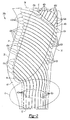
- a first embodiment of one fan blade detail half 30a is shown in Figure 2 .
- the other fan blade detail half 30b would be complementary.
- the fan blade detail half 30a comprises a substrate 31, preferably Titanium, having a root edge 32 opposite a tip 34 and a leading edge 36 opposite a trailing edge 38.
- the fan blade detail half 30a includes Region A, which is approximately the radially inner-most third adjacent the root edge 32.
- Region B extends from Region A toward the tip 34, excluding a corner area adjacent the tip 34 and trailing edge 38, which is Region C.
- a plurality of elongated continuous cavities 40a-d arc machined into the interior surface of the substrate 31.
- the cavities 40a-d are spaced from one another to form a plurality of continuous, non-intersecting ribs 42a-d.
- the ribs 42a-d are superplastically formed.
- the reference numeral 40 may be used to refer to the cavities 40 generically, while for specific subsets of cavities 40, the reference numeral 40 will be appended with one or more of the letters a-d.
- the reference numeral 42 may be used generically for the ribs 42a-d.
- the ribs 42 are oriented and biased in order to provide stiffness where needed, both during forming and during use in the turbine engine 10 of Figure 1 . Further, the ribs 42 curve and change direction to eliminate any long, straight cavities 40, which would have low inertia. Preferably, the cavities 40 do not continue in any direction for lengths greater than half the blade chord.
- a first subset of cavities 40a and ribs 42a extend continuously from the root edge 32 toward the leading edge 36.
- the cavities 40a and ribs 42a extend from the root-edge 32 initially radially outward (i.e. toward the tip 34) in Region A and then curve slightly away from and then toward the leading edge 36 at substantially a 45 degree angle but in a curved path in Region B.
- Region A is an area of significant blade pull (i.e. P/A).
- the portions of the ribs 42a in Region A help carry the load on the blade half 30a.
- the radially-extending portions of ribs 42a also minimize any stress concentration from the fillets.
- the slight curves in Region A prevent cavity 40a collapse during the forming process, when the fan blade detail half 30a is formed to its desired shape.
- a second subset of cavities 40b and ribs 42b extend continuously from the leading edge 36 toward the trailing edge 38 and curve downwardly slightly toward the root edge 32 at approximately a 45 degree angle, but in a curved path. These portions of the ribs 42a and ribs 42b in Region B extend substantially chordwise (at approximately a 45 degree angle) at the leading edge to provide bird strike stiffness.
- a third subset of cavities 40c and ribs 42c extend continuously along a curve approximately 45 degree chordwise path and then sharply curve perpendicularly to extend substantially radially toward the tip 34 and trailing edge 38 at approximately a 60 degree angle.
- a fourth subset of cavities 40d and ribs 42d extend continuously along a curved path substantially radially and toward the tip 34 and the trailing edge 38 at an approximately 60 degree angle.
- these ribs 42c and 42d are oriented transversely to the tip 34 to provide strength in the event of a tip 34 rub on the inner surface of the fan housing. Rib orientation in Region C is close to perpendicular to rib orientation of Region B where they meet in order to minimize mass of the fillets, which are a result of the cutter radius.
- stiffness is needed in the radial direction for tip rub events.
- Diagonal stiffness is needed in the corners adjacent the tip 34 and leading edge 36 and adjacent the tip 34 and trailing edge 38.
- the cavities 40 arc all formed in the substrate 31 between the root edge 32 and the tip 34, and between the leading edge 36 and trailing edge 38.
- a frame 44 that is substantially equal to the thickness of the ribs 42.
- Each of the ribs 42 is contiguous with the frame 44 at both ends.
- Each of the cavities 40 begins and terminales adjacent the frame 44. The termination points occur in regions where the airfoil thickness is relatively low, which reduces the depth the cutters have to plunge into the part to start machining.
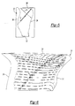
- FIG. 3 is a sectional view of the detail half 30a being machined by a cutter 54.
- Each cavity 40 has a floor 48 between opposite wall interior surfaces 50, some of which define the ribs 42.
- Each cavity 40 further includes a radius 42 transition between the wall interior surface 50 and the floor 48.
- the floor 48 and both wall interior surfaces 50 are preferably cut simultaneously in a single pass by the cutter 54. Because the cavities 40 are continuous and the ribs 42 do not intersect, cach cavity 40 is formed in a single pass with a single cutter. Alternatively, the cavities 40 may each be formed in a single rough cut and a second, finish cut, but this is still a significant reduction in the number of cuts and cutters required.
- Figure 4 is a sectional view of a portion of the fan blade 30.
- the ribs 42 of fan blade detail half 30a are aligned and joined with the ribs 42 of the fan blade detail half 30b.
- the ribs 42 arc tapered and transition into a compound radius (including radius 52 and the floor 48) that simulates the classical arch design element.
- the two radii (of the radius 52 and floor 48) should be selected such that the transition between each other and the tapered wall geometry are smooth and gradual. The sizing will depend upon the required load transitioning and carrying capabilities.
- the ratio of the width w of the cavity at the rib wall fillet run out to the thickness t of the floor 48 should be less than ten, but can be larger if the rib can be aligned more parallel to the load.
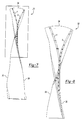
- the fan blade 30 is given an airfoil shape in a forming operation, which is illustrated in Figures 5-9 .
- the two detail halves arc twisted and cambered to the desired shape under high heat.
- the cavities 40 do not require a high pressure gas to increase their strength and prevent cavity collapse during the forming operation. This reduces the time and expense of the forming operation as the pressure within the cavities can be substantially ambient pressure.
- Figure 5 is a rear view of the assembled fan blade 30 of Figure 4 , illustrating two section lines, a and b, through the fan blade 30.
- Figure 6 is an enlarged, top perspective view of the fan blade of Figure 5 .
- the section line a extends from a position generally near the corner of the tip 34 and leading edge 36 rearwardly to the trailing edge 38 and downwardly toward the root edge 32 ( Figure 5 ).
- the section lines a, b assist in visualizing the twisting and cambering of the fan blade 30 relative to the ribs 42 and cavities 40.
- Figure 7 is a front view of the fan blade of Figure 4 after the forming operation, showing the resulting locations of sections a and b.
- Figure 8 is an enlarged view of the upper portion of the fan blade of Figure 7 .
- Figure 9 is top view of the fan blade of Figure 7 .
- the orientation of the ribs 42 should be in a parallel plane with the load vector that results from forming loads during the pre-form and final form operations. This orientation presents the optimum configuration for load carrying capability and compressive stress transfer into the ribs 42 and away from the concave and convex skins.
- the specific orientation of the ribs 42 is therefore dependent upon the final shape of the fan blade 30, which will vary from one engine to another. Obviously, there are trade-offs and balancing among the various requirements as described herein, such that the ribs 42 cannot always be completely in a parallel plane with the load vector. For this reason ribs totally straight are avoided.
- FIG 10 illustrates a second embodiment of a fan blade detail half 60a that could be used in the turbine engine 10 of Figure 1 .
- the fan blade detail half 60a comprises a substrate 61, preferably Titanium, having a root edge 62 opposite a tip 64 and a leading edge 66 opposite a trailing edge 68.
- a plurality of elongated continuous cavities 70 are machined into or superplastically or otherwise formed on the interior surface of the substrate 61 in the manner described above with respect to Figures 3 and 4 .
- the cavities 70 are spaced from one another to form a Plurality of continuous non-intersecting ribs 72, 73. In this embodiment the spacing between ribs is held constant throughout.
- the cavities 70a-d extend continuously alongside ribs 72a-c and ribs 73.
- the cavities 70a-d also extend around freestanding ends 74 of some of the ribs 72a-c, thereby reducing the number of cavities 70a-d.
- the fan blade detail half 60a includes Region A, which is approximately the radially inward half.
- Region B comprises approximately a quarter adjacent the leading edge 66 and the tip 64.
- Region C comprises approximately a quarter adjacent the trailing edge 68 and the tip 64.
- a transition region is the central area substantially defined among the Regions A, B and C.
- a first subset of cavities 70a and ribs 72a extend continuously from the root edge 62 initially radially outward in Region A, and then curving toward the leading edge 36 at substantially a 45 degree angle but in a curved path in Region B.
- each cavity 70a extends continuously around a freestanding end 74 of one of the ribs 72a, thereby reducing the number of cavities 70a.
- Ribs 73 extend continuously parallel to the ribs 72a from the root edge 62 to the leading edge 66 between adjacent cavities 70a.
- a second subset of cavities 70b and ribs 72b extend continuously from the root edge 62 initially radially outward toward the tip 64 in Region A adjacent the trailing edge 68, and curving slightly toward the leading edge 66 in the transition region and then toward the trailing edge 68 at approximately a 45 degree angle in a slightly curved path in Region C.
- Each cavity 70b also extends continuously around a freestanding end 74 of one of the ribs 72b, thereby reducing the number of cavities 70b.
- Ribs 73 are defined between adjacent cavities 70b and are parallel to the ribs 72b.
- a third subset of ribs 72c extend from the leading edge 66 toward the trailing edge 68 and curve downwardly slightly toward the root edge 62 in a curved path in Region B.
- At least one cavity 70c extends continuously in a serpentine path around one free end 74 of one rib 72c, around the opposite free end 74 of the next rib 72c and again around the opposite free end 74 of the next rib 72c.
- the serpentine path further reduces the number of cavities 70 needed to define the ribs 72.
- a fourth set of ribs 72d are each at least partially defined by a single cavity 70d.
- the cavity 70d and a rib 72d extend continuously from the root edge 62 radially outward (toward the tip 64) in Region A, then curve slightly toward the leading edge 66 in the transition region, and then slightly toward the trailing edge 68 at an approximately 60 degree angle in Region C.
- the cavity 70d extends continuously around the free end 74 of the rib 72d and then around alternating free ends 74 of two more ribs 72d oriented approximately 60 degrees toward the tip 64.
- the cavity 70d then extends continuously into Region B around alternating free ends 74 of a plurality of ribs 72e oriented substantially parallel to the ribs 72c, i.e. substantially chordwise, approximately 30 degrees and curved slightly. This long serpentine path of cavity 70d further reduces the number of cavities 70 necessary to create ribs 72.
- Region A is an area of significant blade pull.
- the portions of the ribs 72a, b, d in Region A help carry the load on the blade half 60a.
- the radially-extending portions of ribs 72a, b, d also minimize any stress concentration from the fillets.
- the substantially chordwise orientation of the portions of ribs 72a, c, d in Region B provide bird strike strength.
- the substantially radial orientation of the portions of the ribs 72b, d in Region C provide strength to the tip in the event of tip rub on interior of the fan housing.
- Figure 11 shows an enlarged view of an alternate rib 72' for the detail half 60a of Figure 10 .
- the alternate rib 72' would also be used in the complementary detail half (not shown).
- the alternate rib 72' has a freestanding end 74' that is flared such that it has a larger width than the rest of the rib 72'.
- the cavity 70 extends continuously around the free, flared end 74' of the rib 72'.
- the ribs 72' are tapered and have a radius 82 transition into the floor 78.
- the radius 82 extends around the flared end 74'.
- the ribs 73' between adjacent cavities 70 have a generally constant width.
- the flared end 74' increases the strength of the bond joint in that location. It also increases the footprint at the base of the fillet, which improves the stiffness in the vicinity of the flared end 74', which reduces the load on the bond joint.
- Figure 12 shows one possible arrangement of a plurality of the ribs 72' with the flared ends 74'. Incorporating the flared ends 74' is achievable with minimum weight impact if the cavity 70 ends can be staggered as shown in Figure 12 .
- the ribs 72' and the cavities 70 that extend continuously around the flared ends 74' of the ribs 72' are staggered, such that the increased width of a flared end 74' of one rib 72'is not aligned with the flared ends 74' of the adjacent ribs 72' (referring to "alignment" in a direction perpendicular to the ribs 72').
- Oblique ribs 72' are a good way to stagger the ends 74'.
- the thickness changes needs to be gradual or they force curvature into successive neighbors as shown in Figure 13 ,
- the flared ends 74', ribs 72' and cavities 70 are not staggered, but are aligned.
- the increase in thickness at the flared ends 74' is taken from a decreased thickness in adjacent ribs 73" between adjacent cavities 70.
Abstract
Description
- The present invention relates generally to gas turbine engines and more particularly to an improved hollow fan blade for a gas turbine engine.
- A gas turbine engine, such as a turbo fan engine for an aircraft, includes a fan section, a compression section, a combustion section and a turbine section. An axis of the engine is centrally disposed within the engine and extends longitudinally through the sections. The primary flow path for working medium gases extends axially through the sections of the engine. A secondary flow path for working medium gases extends parallel to and radially outward of the primary flow path.
- The fan section includes a rotor assembly and a stator assembly. The rotor assembly of the fan includes a rotor disc and plurality of radially extending fan blades. The fan blades extend through the flow path and interact with the working medium gases and transfer energy between the fan blades and working medium gases. The stator assembly includes a fan case, which circumscribes the rotor assembly in close proximity to the tips of the fan blades.
- During operation, the fan draws the working medium gases, more particularly air, into the engine. The fan raises the pressure of the air drawn along the secondary flow path, thus producing useful thrust. The air drawn along the primary flow path into the compressor section is compressed. The compressed air is channeled to the combustion section where fuel is added to the compressed air and the air/fuel mixture is burned. The products of combustion are discharged to the turbine section. The turbine section extracts work from these products to power the fan and compressed air. Any energy from the products of combustion not needed to drive the fan and compressor contributes to useful thrust.
- In order to reduce weight, the fan blades in some gas turbine engines are hollow Each fan blade is made by combining two separate detail halves, Each half includes a plurality of cavities and ribs machined out to reduce the weight while forming a structurally sound internal configuration. These halves are subsequently bonded to form the hollow fan blade. The hollow fan blade is then subjected to forming operations at extremely high temperatures at which time it is given an airfoil shape and geometry. During the forming operation, the two detail halves are twisted and cambered under high temperatures to the desired shape. Inherent to the hollow fan blade design is a set of "skins" on the convex and concave side of the airfoil. These skins undergo significant compressive loading during the bonding and forming operations. At elevated temperatures, these skins do no possess the robustness to withstand this loading, and deform by sagging or drooping inward toward the center of the blade. To prevent collapse of the cavities during the forming process, the cavities are filled with high-pressure gas to maintain their geometry during the forming operation.
- To a large extent, the internal geometry of the hollow fan blades has been designed to provide bird-impact capabilities. The previous hollow fan blades had an internal geometry comprising numerous machined internal cavities and associated ribs primarily running radially with secondary ribs running chord-wise.
- There are several drawbacks to the known hollow fan blades. First, using the high-pressure gas required during forming operation increases time and cost of the operation. Additionally, the intersecting ribs in the hollow fan blades require numerous different diameter cutters and numerous cutting operations to achieve the small fillets that the objectives dictate. This also increases the time and cost of manufacturing the hollow fan blades.
- The present invention provides a method for making a hollow fan blade as claimed in claim 1.
- Also disclosed is a hollow fan blade with internal cavity and rib geometry with improved durability that permits the bonding and forming to be performed without the need for gas pressurization. This reduces the time and cost of manufacturing the hollow fan blade.
- The ability to form the hollow fan blade of the present invention without gas pressurization is a result of the cavity and rib geometry and the orientation of the ribs. In a first aspect of the invention, the ribs are tapered and transition into a compound radius of the floor that, in a preferred embodiment, simulates the classical arch design element. The orientation of the ribs is preferably generally in a parallel plane with the load vector that results from forming loads during the pre-form and final form operations. This orientation provides compressive stress transfer into the ribs and away from the concave and convex skins.
- Other advantages of the present invention can be understood by reference to the following detailed description when considered in connection with the accompanying drawings wherein:
-
Figure 1 is a sectional view of an axial flow, turbo fan gas turbine engine with the hollow fan blades of the present invention. -
Figure 2 is a plan view of one detailed half of one of the hollow fan blades ofFigure 1 . -
Figure 3 is a sectional view through three of the cavities of the detail half ofFigure 2 and through a cutter for forming the cavities. -
Figure 4 is a sectional view through an assembled fan blade corresponding to the fan blade detail half ofFigure 3 . -
Figure 5 is a rear view of the assembled fan blade ofFigure 4 , illustrating two section lines. -
Figure 6 is an enlarged, top perspective view of the fan blade ofFigure 5 . -
Figure 7 is a front view of the fan blade ofFigure 4 , after the twisting and cambering operation. -
Figure 8 is an enlarged view of the upper portion of the fan blade ofFigure 7 . -
Figure 9 is top view of the fan blade ofFigure 7 . -
Figure 10 is a plan view of an alternate detail half for the fan blades shown inFig. 1 . -
Figure 11 is an enlarged view of an alternate rib for the detail halt ofFigure 10 . -
Figure 12 shows one arrangement for a plurality of the alternate ribs ofFigure 11 . -
Figure 13 shows another arrangement for a plurality of the alternate ribs ofFigure 11 . - A
gas turbine engine 10, such as a turbofan gas turbine engine, circumferentially disposed about an engine centerline, oraxial centerline axis 12 is shown. Theengine 10 includes afan 14, acompressor 16, acombustion section 18 and aturbine 20. As is well known in the art, air compressed in thecompressor 16 is mixed with fuel which is burned in thecombustion section 18 and expanded inturbine 20. The air compressed in the compressor and the fuel mixture expanded in theturbine 20 can both be referred to as a hotgas stream flow 28. Theturbine 20 includesrotors 22 which rotate in response to the expansion, driving thecompressor 16 andfan 14. Theturbine 20 comprises alternating rows of rotary airfoils orblades 24 and static airfoils orvancs 26. - The
fan 14 is surrounded by afan case 27 and includes a rotor assembly. The rotor assembly includes arotor disk 29 and a plurality offan blades 30. Eachfan blade 30 extends radially outwardly from therotor disk 29 across the working medium flow paths into proximity with thefan case 27. Thefan blades 30 are hollow fan blades and include a first hollow fan blade detail half 30a and a second hollow fan blade detail half 30b. - A first embodiment of one fan
blade detail half 30a is shown inFigure 2 . The other fanblade detail half 30b would be complementary. The fanblade detail half 30a comprises asubstrate 31, preferably Titanium, having aroot edge 32 opposite atip 34 and aleading edge 36 opposite a trailingedge 38. The fanblade detail half 30a includes Region A, which is approximately the radially inner-most third adjacent theroot edge 32. Region B extends from Region A toward thetip 34, excluding a corner area adjacent thetip 34 and trailingedge 38, which is Region C. - In order to reduce weight while still maintaining the necessary stiffness and strength, a plurality of elongated
continuous cavities 40a-d arc machined into the interior surface of thesubstrate 31. Thecavities 40a-d are spaced from one another to form a plurality of continuous,non-intersecting ribs 42a-d. Alternatively (or additionally), theribs 42a-d are superplastically formed. Throughout this description, thereference numeral 40 may be used to refer to thecavities 40 generically, while for specific subsets ofcavities 40, thereference numeral 40 will be appended with one or more of the letters a-d. Similarly, thereference numeral 42 may be used generically for theribs 42a-d. - The
ribs 42 are oriented and biased in order to provide stiffness where needed, both during forming and during use in theturbine engine 10 ofFigure 1 . Further, theribs 42 curve and change direction to eliminate any long,straight cavities 40, which would have low inertia. Preferably, thecavities 40 do not continue in any direction for lengths greater than half the blade chord. - A first subset of
cavities 40a andribs 42a extend continuously from theroot edge 32 toward the leadingedge 36. Thecavities 40a andribs 42a extend from the root-edge 32 initially radially outward (i.e. toward the tip 34) in Region A and then curve slightly away from and then toward the leadingedge 36 at substantially a 45 degree angle but in a curved path in Region B. Region A is an area of significant blade pull (i.e. P/A). The portions of theribs 42a in Region A help carry the load on theblade half 30a. The radially-extending portions ofribs 42a also minimize any stress concentration from the fillets. The slight curves in Region A preventcavity 40a collapse during the forming process, when the fanblade detail half 30a is formed to its desired shape. - In Region B, a second subset of
cavities 40b andribs 42b extend continuously from the leadingedge 36 toward the trailingedge 38 and curve downwardly slightly toward theroot edge 32 at approximately a 45 degree angle, but in a curved path. These portions of theribs 42a andribs 42b in Region B extend substantially chordwise (at approximately a 45 degree angle) at the leading edge to provide bird strike stiffness. - A third subset of
cavities 40c andribs 42c extend continuously along a curve approximately 45 degree chordwise path and then sharply curve perpendicularly to extend substantially radially toward thetip 34 and trailingedge 38 at approximately a 60 degree angle. A fourth subset ofcavities 40d andribs 42d extend continuously along a curved path substantially radially and toward thetip 34 and the trailingedge 38 at an approximately 60 degree angle. In Region C, theseribs tip 34 to provide strength in the event of atip 34 rub on the inner surface of the fan housing. Rib orientation in Region C is close to perpendicular to rib orientation of Region B where they meet in order to minimize mass of the fillets, which are a result of the cutter radius. - Generally, near the
tip 34, stiffness is needed in the radial direction for tip rub events. Diagonal stiffness is needed in the corners adjacent thetip 34 and leadingedge 36 and adjacent thetip 34 and trailingedge 38. - The
cavities 40 arc all formed in thesubstrate 31 between theroot edge 32 and thetip 34, and between theleading edge 36 and trailingedge 38. Along eachedge frame 44 that is substantially equal to the thickness of theribs 42. Each of theribs 42 is contiguous with theframe 44 at both ends. Each of thecavities 40 begins and terminales adjacent theframe 44. The termination points occur in regions where the airfoil thickness is relatively low, which reduces the depth the cutters have to plunge into the part to start machining. -
Figure 3 is a sectional view of thedetail half 30a being machined by acutter 54. Eachcavity 40 has afloor 48 between opposite wall interior surfaces 50, some of which define theribs 42. Eachcavity 40 further includes aradius 42 transition between the wallinterior surface 50 and thefloor 48. As shown, thefloor 48 and both wall interior surfaces 50 are preferably cut simultaneously in a single pass by thecutter 54. Because thecavities 40 are continuous and theribs 42 do not intersect,cach cavity 40 is formed in a single pass with a single cutter. Alternatively, thecavities 40 may each be formed in a single rough cut and a second, finish cut, but this is still a significant reduction in the number of cuts and cutters required. Additionally, because floor radius is relatively large and approximately follows the curvature of the external surface of thecutter 54 can be operated by a 3-axis machine 55 (shown schematically), instead of the previously-required 5-axis machine. In addition, because there are no transversely-extending ribs intersecting theribs 42 the number of cutters of different diameters required is greatly reduced. A detail half could conceivably be done with a single form cutter, including both rough and finish passes. The other fanblade detail half 30b would be made in a similar manner. -
Figure 4 is a sectional view of a portion of thefan blade 30. Theribs 42 of fanblade detail half 30a are aligned and joined with theribs 42 of the fanblade detail half 30b. To provide increased strength during forming and during use, theribs 42 arc tapered and transition into a compound radius (includingradius 52 and the floor 48) that simulates the classical arch design element. The two radii (of theradius 52 and floor 48) should be selected such that the transition between each other and the tapered wall geometry are smooth and gradual. The sizing will depend upon the required load transitioning and carrying capabilities. Preferably, the ratio of the width w of the cavity at the rib wall fillet run out to the thickness t of thefloor 48 should be less than ten, but can be larger if the rib can be aligned more parallel to the load. - After the
halves 30a,b are bonded, thefan blade 30 is given an airfoil shape in a forming operation, which is illustrated inFigures 5-9 . During the forming operation, the two detail halves arc twisted and cambered to the desired shape under high heat. Because of the orientation and shape, as well as the spacing, of theribs 42 as described and shown, thecavities 40 do not require a high pressure gas to increase their strength and prevent cavity collapse during the forming operation. This reduces the time and expense of the forming operation as the pressure within the cavities can be substantially ambient pressure. -
Figure 5 is a rear view of the assembledfan blade 30 ofFigure 4 , illustrating two section lines, a and b, through thefan blade 30.Figure 6 is an enlarged, top perspective view of the fan blade ofFigure 5 . As can be seen inFigure 6 , the section line a extends from a position generally near the corner of thetip 34 and leadingedge 36 rearwardly to the trailingedge 38 and downwardly toward the root edge 32 (Figure 5 ). The section lines a, b assist in visualizing the twisting and cambering of thefan blade 30 relative to theribs 42 andcavities 40. -
Figure 7 is a front view of the fan blade ofFigure 4 after the forming operation, showing the resulting locations of sections a and b.Figure 8 is an enlarged view of the upper portion of the fan blade ofFigure 7 .Figure 9 is top view of the fan blade ofFigure 7 . As can be seen by referencingFigure 5 with respect toFigures 7-9 , the orientation of theribs 42 should be in a parallel plane with the load vector that results from forming loads during the pre-form and final form operations. This orientation presents the optimum configuration for load carrying capability and compressive stress transfer into theribs 42 and away from the concave and convex skins. The specific orientation of theribs 42 is therefore dependent upon the final shape of thefan blade 30, which will vary from one engine to another. Obviously, there are trade-offs and balancing among the various requirements as described herein, such that theribs 42 cannot always be completely in a parallel plane with the load vector. For this reason ribs totally straight are avoided. -
Figure 10 illustrates a second embodiment of a fanblade detail half 60a that could be used in theturbine engine 10 ofFigure 1 . Again, the other fan blade detail half (not shown) would be complementary. The fanblade detail half 60a comprises asubstrate 61, preferably Titanium, having aroot edge 62 opposite atip 64 and aleading edge 66 opposite a trailingedge 68. A plurality of elongatedcontinuous cavities 70 are machined into or superplastically or otherwise formed on the interior surface of thesubstrate 61 in the manner described above with respect toFigures 3 and 4 . Thecavities 70 are spaced from one another to form a Plurality of continuousnon-intersecting ribs - In the second embodiment, the
cavities 70a-d extend continuously alongsideribs 72a-c andribs 73. Thecavities 70a-d also extend aroundfreestanding ends 74 of some of theribs 72a-c, thereby reducing the number ofcavities 70a-d. - The fan
blade detail half 60a includes Region A, which is approximately the radially inward half. Region B comprises approximately a quarter adjacent the leadingedge 66 and thetip 64. Region C comprises approximately a quarter adjacent the trailingedge 68 and thetip 64. A transition region is the central area substantially defined among the Regions A, B and C. - A first subset of
cavities 70a andribs 72a extend continuously from theroot edge 62 initially radially outward in Region A, and then curving toward the leadingedge 36 at substantially a 45 degree angle but in a curved path in Region B. In Region B, eachcavity 70a extends continuously around afreestanding end 74 of one of theribs 72a, thereby reducing the number ofcavities 70a.Ribs 73 extend continuously parallel to theribs 72a from theroot edge 62 to the leadingedge 66 betweenadjacent cavities 70a. - A second subset of
cavities 70b andribs 72b extend continuously from theroot edge 62 initially radially outward toward thetip 64 in Region A adjacent the trailingedge 68, and curving slightly toward the leadingedge 66 in the transition region and then toward the trailingedge 68 at approximately a 45 degree angle in a slightly curved path in Region C. Eachcavity 70b also extends continuously around afreestanding end 74 of one of theribs 72b, thereby reducing the number ofcavities 70b.Ribs 73 are defined betweenadjacent cavities 70b and are parallel to theribs 72b. - A third subset of ribs 72c extend from the leading
edge 66 toward the trailingedge 68 and curve downwardly slightly toward theroot edge 62 in a curved path in Region B. At least onecavity 70c extends continuously in a serpentine path around onefree end 74 of one rib 72c, around the oppositefree end 74 of the next rib 72c and again around the oppositefree end 74 of the next rib 72c. The serpentine path further reduces the number ofcavities 70 needed to define theribs 72. - A fourth set of
ribs 72d are each at least partially defined by asingle cavity 70d. Thecavity 70d and arib 72d extend continuously from theroot edge 62 radially outward (toward the tip 64) in Region A, then curve slightly toward the leadingedge 66 in the transition region, and then slightly toward the trailingedge 68 at an approximately 60 degree angle in Region C. Near thetip 64, thecavity 70d extends continuously around thefree end 74 of therib 72d and then around alternating free ends 74 of twomore ribs 72d oriented approximately 60 degrees toward thetip 64. Thecavity 70d then extends continuously into Region B around alternating free ends 74 of a plurality ofribs 72e oriented substantially parallel to the ribs 72c, i.e. substantially chordwise, approximately 30 degrees and curved slightly. This long serpentine path ofcavity 70d further reduces the number ofcavities 70 necessary to createribs 72. - Again, Region A is an area of significant blade pull. The portions of the
ribs 72a, b, d in Region A help carry the load on theblade half 60a. The radially-extending portions ofribs 72a, b, d also minimize any stress concentration from the fillets. The substantially chordwise orientation of the portions ofribs 72a, c, d in Region B provide bird strike strength. The substantially radial orientation of the portions of theribs 72b, d in Region C provide strength to the tip in the event of tip rub on interior of the fan housing. - By machining
contiguous cavities 70 aroundfreestanding ends 74 of theribs 72,fewer cavities 70 arc required, thereby reducing time and cost. However, the freestanding ends 74 of theribs 72 may cause a variation in the stiffness, which can act as a stress concentration when the blade sees externally applied loads, such as from bird impact or heavy bending moments from a released neighboring blade during a blade out event. Therefore,Figure 11 shows an enlarged view of an alternate rib 72' for thedetail half 60a ofFigure 10 . The alternate rib 72' would also be used in the complementary detail half (not shown). The alternate rib 72' has afreestanding end 74' that is flared such that it has a larger width than the rest of the rib 72'. Thecavity 70 extends continuously around the free, flaredend 74' of the rib 72'. The ribs 72' are tapered and have aradius 82 transition into thefloor 78. Theradius 82 extends around the flaredend 74'. Theribs 73' betweenadjacent cavities 70 have a generally constant width. The flaredend 74' increases the strength of the bond joint in that location. It also increases the footprint at the base of the fillet, which improves the stiffness in the vicinity of the flaredend 74', which reduces the load on the bond joint. - Because it would be impractical to vary the width of the cutter and the
cavity 70,Figure 12 shows one possible arrangement of a plurality of the ribs 72' with the flared ends 74'. Incorporating the flared ends 74' is achievable with minimum weight impact if thecavity 70 ends can be staggered as shown inFigure 12 . InFigure 12 , the ribs 72' and thecavities 70 that extend continuously around the flared ends 74' of the ribs 72' are staggered, such that the increased width of a flaredend 74' of one rib 72'is not aligned with the flared ends 74' of the adjacent ribs 72' (referring to "alignment" in a direction perpendicular to the ribs 72'). Oblique ribs 72' are a good way to stagger theends 74'. - Where stagger is not feasible, the thickness changes needs to be gradual or they force curvature into successive neighbors as shown in
Figure 13 , InFigure 13 , the flared ends 74', ribs 72' andcavities 70 are not staggered, but are aligned. In this case, the increase in thickness at the flared ends 74' is taken from a decreased thickness inadjacent ribs 73" betweenadjacent cavities 70. - In accordance with the provisions of the patent statutes and jurisprudence, exemplary configurations described above are considered to represent a preferred embodiment of the invention. However, it should be noted that the invention can be practiced otherwise than as specifically illustrated and described without departing from its spirit or scope. Alphanumeric identifiers for steps in the method claims are for ease of reference by dependent claims, and do not indicate a required sequence, unless otherwise indicated.
Claims (8)
- A method for making a hollow fan blade including the steps of:a) forming a plurality of ribs (42;72) on a first substrate (31;61 the first substrate (31;61) including cavities (40;70) on either side of each of the plurality of ribs;b) abutting the plurality of ribs (42;72) on the first substrate (31;61) with a second substrate (31 ;61) to form a hollow fan blade (30);c) forming the hollow fan blade (30) into an airfoil shape while pressure inside the cavities (40;70) is substantially ambient pressure.
- The method of claim 1 wherein said step c) further includes the step of subjecting the hollow fan blade (30) to high temperature while forming the airfoil shape.
- The method of claim 1 or 2 wherein the cavities (40;70) are not pressurized during said step c) in order to prevent collapse of the cavities.
- The method of any of claims 1 to 3 further including the step of forming a plurality of ribs (42;72) on the second substrate and wherein said step b) further includes the step of abutting the ribs on the first substrate with the ribs on the second substrate.
- The method of any of claims 1 to 4 wherein each of the ribs (42;72) is tapered to transition into a compound radius in an adjacent one of the cavities (40;70).
- The method of any of claims 1 to 5 wherein said step c) further includes the step of applying a forming load having a load vector and wherein the plurality of ribs (42;72) arc each in a parallel plane parallel to the load vector.
- The method of any of claims 1 to 6 wherein widths of the cavities (40;70) are each less than 10 times a thickness of the substrate (31;61) in the associated cavity.
- A hollow fan blade detail half (30a) comprising:a substrate (31;61) having a root edge (32;62) and an opposite tip (34;64) spaced radially outward from the root, the substrate further including a leading edge (36;66) opposite a trailing edge (38;68), the leading edge spaced chordwise from the trailing edge; anda plurality of tapered ribs (42;72) formed on the substrate, each of the ribs adjacent a cavity (40;70), the rib transitioning from the taper to a compound radius in the cavity.
Applications Claiming Priority (2)
| Application Number | Priority Date | Filing Date | Title |
|---|---|---|---|
| US10/765,593 US7052238B2 (en) | 2004-01-26 | 2004-01-26 | Hollow fan blade for gas turbine engine |
| EP05250320A EP1557529B1 (en) | 2004-01-26 | 2005-01-24 | Hollow fan blade for gas turbine engine and corresponding manufacturing method |
Related Parent Applications (2)
| Application Number | Title | Priority Date | Filing Date |
|---|---|---|---|
| EP05250320.8 Division | 2005-01-24 | ||
| EP05250320A Division EP1557529B1 (en) | 2004-01-26 | 2005-01-24 | Hollow fan blade for gas turbine engine and corresponding manufacturing method |
Publications (3)
| Publication Number | Publication Date |
|---|---|
| EP1982791A2 true EP1982791A2 (en) | 2008-10-22 |
| EP1982791A3 EP1982791A3 (en) | 2011-09-28 |
| EP1982791B1 EP1982791B1 (en) | 2012-12-05 |
Family
ID=34634637
Family Applications (2)
| Application Number | Title | Priority Date | Filing Date |
|---|---|---|---|
| EP08012586A Active EP1982791B1 (en) | 2004-01-26 | 2005-01-24 | Manufacturing method for a hollow fan blade |
| EP05250320A Active EP1557529B1 (en) | 2004-01-26 | 2005-01-24 | Hollow fan blade for gas turbine engine and corresponding manufacturing method |
Family Applications After (1)
| Application Number | Title | Priority Date | Filing Date |
|---|---|---|---|
| EP05250320A Active EP1557529B1 (en) | 2004-01-26 | 2005-01-24 | Hollow fan blade for gas turbine engine and corresponding manufacturing method |
Country Status (5)
| Country | Link |
|---|---|
| US (1) | US7052238B2 (en) |
| EP (2) | EP1982791B1 (en) |
| JP (1) | JP4109261B2 (en) |
| AT (1) | ATE401161T1 (en) |
| DE (1) | DE602005008119D1 (en) |
Families Citing this family (15)
| Publication number | Priority date | Publication date | Assignee | Title |
|---|---|---|---|---|
| US7458780B2 (en) * | 2005-08-15 | 2008-12-02 | United Technologies Corporation | Hollow fan blade for gas turbine engine |
| US7993105B2 (en) * | 2005-12-06 | 2011-08-09 | United Technologies Corporation | Hollow fan blade for gas turbine engine |
| US8257035B2 (en) * | 2007-12-05 | 2012-09-04 | Siemens Energy, Inc. | Turbine vane for a gas turbine engine |
| US20110211965A1 (en) * | 2010-02-26 | 2011-09-01 | United Technologies Corporation | Hollow fan blade |
| US8562286B2 (en) * | 2010-04-06 | 2013-10-22 | United Technologies Corporation | Dead ended bulbed rib geometry for a gas turbine engine |
| FR2978196B1 (en) | 2011-07-20 | 2016-12-09 | Snecma | TURBOMACHINE AUB COMPRISING A PLATE REPORTED ON A MAIN PART |
| US8807925B2 (en) * | 2011-09-23 | 2014-08-19 | United Technologies Corporation | Fan blade having internal rib break-edge |
| US8801367B2 (en) * | 2011-09-23 | 2014-08-12 | United Technologies Corporation | Hollow fan blade channel configuration to reduce stress |
| US8807924B2 (en) * | 2011-09-23 | 2014-08-19 | United Technologies Corporation | Fan blade channel termination |
| US9587492B2 (en) | 2012-05-04 | 2017-03-07 | General Electric Company | Turbomachine component having an internal cavity reactivity neutralizer and method of forming the same |
| US9169731B2 (en) | 2012-06-05 | 2015-10-27 | United Technologies Corporation | Airfoil cover system |
| ITCO20120059A1 (en) * | 2012-12-13 | 2014-06-14 | Nuovo Pignone Srl | METHODS FOR MANUFACTURING SHAPED SHAPED LOAFERS IN 3D OF TURBOMACCHINE BY ADDITIVE PRODUCTION, TURBOMACCHINA CAVE BLOCK AND TURBOMACCHINE |
| CN105736462B (en) * | 2014-12-12 | 2018-03-06 | 中国航发商用航空发动机有限责任公司 | hollow blade and aero-engine |
| CN106126843B (en) * | 2016-06-28 | 2019-08-30 | 明阳智慧能源集团股份公司 | A kind of Bladed blower load processing system based on Matlab |
| CN111535870B (en) * | 2020-05-06 | 2022-08-05 | 北京南方斯奈克玛涡轮技术有限公司 | Engine turbine intermediate supporting device containing hollowed-out fins and manufactured in additive mode |
Citations (1)
| Publication number | Priority date | Publication date | Assignee | Title |
|---|---|---|---|---|
| EP0468221A2 (en) | 1990-06-27 | 1992-01-29 | Compressor Components Textron Inc. | Method of making hollow articles |
Family Cites Families (9)
| Publication number | Priority date | Publication date | Assignee | Title |
|---|---|---|---|---|
| US3017159A (en) * | 1956-11-23 | 1962-01-16 | Curtiss Wright Corp | Hollow blade construction |
| US3628226A (en) * | 1970-03-16 | 1971-12-21 | Aerojet General Co | Method of making hollow compressor blades |
| FR2516165B1 (en) * | 1981-11-10 | 1986-07-04 | Snecma | GAS TURBINE BLADE WITH FLUID CIRCULATION COOLING CHAMBER AND METHOD FOR PRODUCING THE SAME |
| US5246340A (en) * | 1991-11-19 | 1993-09-21 | Allied-Signal Inc. | Internally cooled airfoil |
| US5269058A (en) * | 1992-12-16 | 1993-12-14 | General Electric Company | Design and processing method for manufacturing hollow airfoils |
| US5836744A (en) * | 1997-04-24 | 1998-11-17 | United Technologies Corporation | Frangible fan blade |
| US5820338A (en) * | 1997-04-24 | 1998-10-13 | United Technologies Corporation | Fan blade interplatform seal |
| US6637186B1 (en) * | 1997-11-11 | 2003-10-28 | United Technologies Corporation | Fan case liner |
| US6607355B2 (en) * | 2001-10-09 | 2003-08-19 | United Technologies Corporation | Turbine airfoil with enhanced heat transfer |
-
2004
- 2004-01-26 US US10/765,593 patent/US7052238B2/en active Active
-
2005
- 2005-01-24 EP EP08012586A patent/EP1982791B1/en active Active
- 2005-01-24 DE DE602005008119T patent/DE602005008119D1/en active Active
- 2005-01-24 EP EP05250320A patent/EP1557529B1/en active Active
- 2005-01-24 AT AT05250320T patent/ATE401161T1/en not_active IP Right Cessation
- 2005-01-25 JP JP2005017037A patent/JP4109261B2/en active Active
Patent Citations (1)
| Publication number | Priority date | Publication date | Assignee | Title |
|---|---|---|---|---|
| EP0468221A2 (en) | 1990-06-27 | 1992-01-29 | Compressor Components Textron Inc. | Method of making hollow articles |
Also Published As
| Publication number | Publication date |
|---|---|
| JP2005264928A (en) | 2005-09-29 |
| EP1557529B1 (en) | 2008-07-16 |
| EP1982791B1 (en) | 2012-12-05 |
| US7052238B2 (en) | 2006-05-30 |
| DE602005008119D1 (en) | 2008-08-28 |
| JP4109261B2 (en) | 2008-07-02 |
| EP1982791A3 (en) | 2011-09-28 |
| EP1557529A2 (en) | 2005-07-27 |
| US20050163620A1 (en) | 2005-07-28 |
| EP1557529A3 (en) | 2006-01-18 |
| ATE401161T1 (en) | 2008-08-15 |
Similar Documents
| Publication | Publication Date | Title |
|---|---|---|
| EP1557528B1 (en) | Hollow fan blade detail half, hollow fan blade for a gas turbine engine and corresponding manufacturing method | |
| EP1557530B1 (en) | Method of making a hollow fan blade for a gas turbine engine | |
| EP1557532B1 (en) | Hollow fan blade detail half, hollow fan blade for a gas turbine engine and corresponding manufacturing method | |
| EP1982791B1 (en) | Manufacturing method for a hollow fan blade | |
| EP1557531B1 (en) | Hollow fan blade half, hollow fan blade for a gas turbine engine and corresponding manufacturing method | |
| EP1795704B1 (en) | Hollow fan blade for gas turbine engine, corresponding gas turbine engine and method for making a hollow fan blade detail half | |
| EP1754857B1 (en) | Hollow fan blade detail half, hollow fan blade for a gas turbine engine, gas turbine engine and corresponding manufacturing method | |
| EP1890008B1 (en) | Rotor blade | |
| EP0924381B1 (en) | Frequency tuned turbomachine blade | |
| EP1199439A2 (en) | Configuration for reducing circumferential rim stress in a rotor assembly | |
| CA2634431A1 (en) | Rotary body for turbo machinery with mistuned blades | |
| EP3399146B1 (en) | Method of manufacturing a vane arrangement for a gas turbine engine | |
| US11591921B1 (en) | Ceramic matrix composite vane assembly |
Legal Events
| Date | Code | Title | Description |
|---|---|---|---|
| PUAI | Public reference made under article 153(3) epc to a published international application that has entered the european phase |
Free format text: ORIGINAL CODE: 0009012 |
|
| AC | Divisional application: reference to earlier application |
Ref document number: 1557529 Country of ref document: EP Kind code of ref document: P |
|
| AK | Designated contracting states |
Kind code of ref document: A2 Designated state(s): AT BE BG CH CY CZ DE DK EE ES FI FR GB GR HU IE IS IT LI LT LU MC NL PL PT RO SE SI SK TR |
|
| PUAL | Search report despatched |
Free format text: ORIGINAL CODE: 0009013 |
|
| AK | Designated contracting states |
Kind code of ref document: A3 Designated state(s): AT BE BG CH CY CZ DE DK EE ES FI FR GB GR HU IE IS IT LI LT LU MC NL PL PT RO SE SI SK TR |
|
| RIC1 | Information provided on ipc code assigned before grant |
Ipc: F04D 29/38 20060101ALI20110819BHEP Ipc: F04D 29/32 20060101ALI20110819BHEP Ipc: F01D 5/18 20060101ALI20110819BHEP Ipc: F01D 5/14 20060101ALI20110819BHEP Ipc: B23P 15/04 20060101AFI20110819BHEP |
|
| 17P | Request for examination filed |
Effective date: 20120328 |
|
| AKX | Designation fees paid |
Designated state(s): DE FR GB |
|
| GRAP | Despatch of communication of intention to grant a patent |
Free format text: ORIGINAL CODE: EPIDOSNIGR1 |
|
| GRAS | Grant fee paid |
Free format text: ORIGINAL CODE: EPIDOSNIGR3 |
|
| GRAA | (expected) grant |
Free format text: ORIGINAL CODE: 0009210 |
|
| AC | Divisional application: reference to earlier application |
Ref document number: 1557529 Country of ref document: EP Kind code of ref document: P |
|
| AK | Designated contracting states |
Kind code of ref document: B1 Designated state(s): DE FR GB |
|
| REG | Reference to a national code |
Ref country code: GB Ref legal event code: FG4D |
|
| REG | Reference to a national code |
Ref country code: DE Ref legal event code: R096 Ref document number: 602005037346 Country of ref document: DE Effective date: 20130131 |
|
| PLBE | No opposition filed within time limit |
Free format text: ORIGINAL CODE: 0009261 |
|
| STAA | Information on the status of an ep patent application or granted ep patent |
Free format text: STATUS: NO OPPOSITION FILED WITHIN TIME LIMIT |
|
| REG | Reference to a national code |
Ref country code: FR Ref legal event code: ST Effective date: 20130930 |
|
| 26N | No opposition filed |
Effective date: 20130906 |
|
| PG25 | Lapsed in a contracting state [announced via postgrant information from national office to epo] |
Ref country code: FR Free format text: LAPSE BECAUSE OF NON-PAYMENT OF DUE FEES Effective date: 20130205 |
|
| REG | Reference to a national code |
Ref country code: DE Ref legal event code: R097 Ref document number: 602005037346 Country of ref document: DE Effective date: 20130906 |
|
| REG | Reference to a national code |
Ref country code: DE Ref legal event code: R082 Ref document number: 602005037346 Country of ref document: DE Representative=s name: SCHMITT-NILSON SCHRAUD WAIBEL WOHLFROM PATENTA, DE |
|
| REG | Reference to a national code |
Ref country code: DE Ref legal event code: R082 Ref document number: 602005037346 Country of ref document: DE Representative=s name: SCHMITT-NILSON SCHRAUD WAIBEL WOHLFROM PATENTA, DE Ref country code: DE Ref legal event code: R081 Ref document number: 602005037346 Country of ref document: DE Owner name: UNITED TECHNOLOGIES CORP. (N.D.GES.D. STAATES , US Free format text: FORMER OWNER: UNITED TECHNOLOGIES CORPORATION, HARTFORD, CONN., US |
|
| PGFP | Annual fee paid to national office [announced via postgrant information from national office to epo] |
Ref country code: DE Payment date: 20191218 Year of fee payment: 16 |
|
| REG | Reference to a national code |
Ref country code: DE Ref legal event code: R119 Ref document number: 602005037346 Country of ref document: DE |
|
| PG25 | Lapsed in a contracting state [announced via postgrant information from national office to epo] |
Ref country code: DE Free format text: LAPSE BECAUSE OF NON-PAYMENT OF DUE FEES Effective date: 20210803 |
|
| PGFP | Annual fee paid to national office [announced via postgrant information from national office to epo] |
Ref country code: GB Payment date: 20231219 Year of fee payment: 20 |