JP4108398B2 - Tire / wheel assembly and run-flat support - Google Patents
Tire / wheel assembly and run-flat support Download PDFInfo
- Publication number
- JP4108398B2 JP4108398B2 JP2002212369A JP2002212369A JP4108398B2 JP 4108398 B2 JP4108398 B2 JP 4108398B2 JP 2002212369 A JP2002212369 A JP 2002212369A JP 2002212369 A JP2002212369 A JP 2002212369A JP 4108398 B2 JP4108398 B2 JP 4108398B2
- Authority
- JP
- Japan
- Prior art keywords
- elastic ring
- rigidity
- run
- tire
- ring
- Prior art date
- Legal status (The legal status is an assumption and is not a legal conclusion. Google has not performed a legal analysis and makes no representation as to the accuracy of the status listed.)
- Expired - Fee Related
Links
- 230000002093 peripheral effect Effects 0.000 claims description 27
- 229920005989 resin Polymers 0.000 description 11
- 239000011347 resin Substances 0.000 description 11
- 229920001971 elastomer Polymers 0.000 description 5
- 239000005060 rubber Substances 0.000 description 5
- 238000012360 testing method Methods 0.000 description 5
- 239000013013 elastic material Substances 0.000 description 4
- 239000000463 material Substances 0.000 description 3
- 239000002184 metal Substances 0.000 description 3
- 229910052751 metal Inorganic materials 0.000 description 3
- 238000000034 method Methods 0.000 description 3
- DOSMHBDKKKMIEF-UHFFFAOYSA-N 2-[3-(diethylamino)-6-diethylazaniumylidenexanthen-9-yl]-5-[3-[3-[4-(1-methylindol-3-yl)-2,5-dioxopyrrol-3-yl]indol-1-yl]propylsulfamoyl]benzenesulfonate Chemical compound C1=CC(=[N+](CC)CC)C=C2OC3=CC(N(CC)CC)=CC=C3C(C=3C(=CC(=CC=3)S(=O)(=O)NCCCN3C4=CC=CC=C4C(C=4C(NC(=O)C=4C=4C5=CC=CC=C5N(C)C=4)=O)=C3)S([O-])(=O)=O)=C21 DOSMHBDKKKMIEF-UHFFFAOYSA-N 0.000 description 2
- 230000000712 assembly Effects 0.000 description 2
- 238000000429 assembly Methods 0.000 description 2
- 239000011324 bead Substances 0.000 description 2
- 229920005992 thermoplastic resin Polymers 0.000 description 2
- 229920001187 thermosetting polymer Polymers 0.000 description 2
- 244000043261 Hevea brasiliensis Species 0.000 description 1
- 239000004677 Nylon Substances 0.000 description 1
- 239000005062 Polybutadiene Substances 0.000 description 1
- 229920005830 Polyurethane Foam Polymers 0.000 description 1
- 229910000831 Steel Inorganic materials 0.000 description 1
- 229910052782 aluminium Inorganic materials 0.000 description 1
- XAGFODPZIPBFFR-UHFFFAOYSA-N aluminium Chemical compound [Al] XAGFODPZIPBFFR-UHFFFAOYSA-N 0.000 description 1
- 229920005549 butyl rubber Polymers 0.000 description 1
- 239000000470 constituent Substances 0.000 description 1
- 125000004122 cyclic group Chemical group 0.000 description 1
- 230000000694 effects Effects 0.000 description 1
- 238000005516 engineering process Methods 0.000 description 1
- 239000003822 epoxy resin Substances 0.000 description 1
- 238000011156 evaluation Methods 0.000 description 1
- 239000000835 fiber Substances 0.000 description 1
- 229920003049 isoprene rubber Polymers 0.000 description 1
- 238000000691 measurement method Methods 0.000 description 1
- 238000002156 mixing Methods 0.000 description 1
- 238000012986 modification Methods 0.000 description 1
- 230000004048 modification Effects 0.000 description 1
- 229920003052 natural elastomer Polymers 0.000 description 1
- 229920001194 natural rubber Polymers 0.000 description 1
- 229920001778 nylon Polymers 0.000 description 1
- 229920002857 polybutadiene Polymers 0.000 description 1
- 229920000647 polyepoxide Polymers 0.000 description 1
- 229920000728 polyester Polymers 0.000 description 1
- 239000011496 polyurethane foam Substances 0.000 description 1
- 239000012783 reinforcing fiber Substances 0.000 description 1
- 239000010959 steel Substances 0.000 description 1
- 229920003048 styrene butadiene rubber Polymers 0.000 description 1
- 229920006337 unsaturated polyester resin Polymers 0.000 description 1
Images
Classifications
-
- B—PERFORMING OPERATIONS; TRANSPORTING
- B60—VEHICLES IN GENERAL
- B60C—VEHICLE TYRES; TYRE INFLATION; TYRE CHANGING; CONNECTING VALVES TO INFLATABLE ELASTIC BODIES IN GENERAL; DEVICES OR ARRANGEMENTS RELATED TO TYRES
- B60C17/00—Tyres characterised by means enabling restricted operation in damaged or deflated condition; Accessories therefor
- B60C17/04—Tyres characterised by means enabling restricted operation in damaged or deflated condition; Accessories therefor utilising additional non-inflatable supports which become load-supporting in emergency
- B60C17/06—Tyres characterised by means enabling restricted operation in damaged or deflated condition; Accessories therefor utilising additional non-inflatable supports which become load-supporting in emergency resilient
-
- B—PERFORMING OPERATIONS; TRANSPORTING
- B60—VEHICLES IN GENERAL
- B60C—VEHICLE TYRES; TYRE INFLATION; TYRE CHANGING; CONNECTING VALVES TO INFLATABLE ELASTIC BODIES IN GENERAL; DEVICES OR ARRANGEMENTS RELATED TO TYRES
- B60C17/00—Tyres characterised by means enabling restricted operation in damaged or deflated condition; Accessories therefor
- B60C17/04—Tyres characterised by means enabling restricted operation in damaged or deflated condition; Accessories therefor utilising additional non-inflatable supports which become load-supporting in emergency
- B60C17/043—Tyres characterised by means enabling restricted operation in damaged or deflated condition; Accessories therefor utilising additional non-inflatable supports which become load-supporting in emergency made-up of an annular metallic shell
-
- Y—GENERAL TAGGING OF NEW TECHNOLOGICAL DEVELOPMENTS; GENERAL TAGGING OF CROSS-SECTIONAL TECHNOLOGIES SPANNING OVER SEVERAL SECTIONS OF THE IPC; TECHNICAL SUBJECTS COVERED BY FORMER USPC CROSS-REFERENCE ART COLLECTIONS [XRACs] AND DIGESTS
- Y10—TECHNICAL SUBJECTS COVERED BY FORMER USPC
- Y10T—TECHNICAL SUBJECTS COVERED BY FORMER US CLASSIFICATION
- Y10T152/00—Resilient tires and wheels
- Y10T152/10—Tires, resilient
- Y10T152/10036—Cushion and pneumatic combined
- Y10T152/10045—Metallic spring cushion
Landscapes
- Engineering & Computer Science (AREA)
- Mechanical Engineering (AREA)
- Tires In General (AREA)
Description
【0001】
【発明の属する技術分野】
本発明は、タイヤ/ホイール組立体及びランフラット用支持体に関し、さらに詳しくは、耐久性を改善するようにしたタイヤ/ホイール組立体及びそれに使用するランフラット用支持体に関する。
【0002】
【従来の技術】
車両の走行中に空気入りタイヤがパンクした場合でも、数百km程度の緊急走行を可能にするようにする技術が市場の要請から多数提案されている。これら多数の提案のうち、特開平10−297226号公報や特表2001−519279号公報で提案された技術は、リム組みされた空気入りタイヤの空洞部内側のリム上に支持体を装着し、その支持体によってパンクしたタイヤを支持することによりランフラット走行を可能にしたものである。
【0003】
上記ランフラット用支持体は、外周側を支持面にすると共に内周側を開脚した開脚構造の環状シェルを有し、その両脚部に弾性リングを取り付けた構成からなり、その弾性リングを介してリム上に支持されるようになっている。このランフラット用支持体によれば、既存のホイール/リムに何ら特別の改造を加えることなく、そのまま使用できるため、市場に混乱をもたらすことなく受入れ可能にできる利点を有している。
【0004】
しかしながら、このようなランフラット用支持体は、その構造上、弾性リングの方が環状シェルよりもランフラット走行時に破壊し易く、ランフラット用支持体の耐久性が弾性リングの耐久性に大きく左右される。従って、上記ランフラット用支持体を装着したタイヤ/ホイール組立体におけるランフラット走行時の耐久性を向上するには、弾性リングの耐久性を改善することが不可欠である。
【0005】
【発明が解決しようとする課題】
本発明の目的は、耐久性を向上することが可能なタイヤ/ホイール組立体及びランフラット用支持体を提供することにある。
【0006】
【課題を解決するための手段】
上記目的を達成する本発明のタイヤ/ホイール組立体は、ホイールのリムに装着した空気入りタイヤの空洞部に、外周側を支持面にすると共に内周側を二股状に開脚した環状シェルと前記二股状に開脚した脚部をリム上に支持する左右の弾性リングとからなるランフラット用支持体を配置したタイヤ/ホイール組立体において、前記弾性リングの剛性を、車両装着時に車両外側となる弾性リングの剛性を車両内側となる弾性リングの剛性より大きくし、前記弾性リングの剛性は、環状シェルを除去した弾性リングをリング周方向に沿って10mmの長さのサンプルに切り出し、室温でそのサンプルにリング径方向の荷重Wを付与した時のリング径方向における撓み量δを測定し、W/δから得られる値であることを特徴とする。
本発明の他のタイヤ/ホイール組立体は、ホイールのリムに装着した空気入りタイヤの空洞部に、外周側を支持面にすると共に内周側を二股状に開脚した環状シェルと前記二股状に開脚した脚部をリム上に支持する左右の弾性リングとからなるランフラット用支持体を配置したタイヤ/ホイール組立体において、前記環状シェルの支持面は、シェル幅方向において曲率半径の異なる少なくとも2個の凸曲面を有し、前記左右の弾性リングは、曲率半径の小さい方の凸曲面側に位置する弾性リングの剛性を大きくしたことを特徴とする。
【0007】
また、本発明のランフラット用支持体は、外周側を支持面にすると共に内周側を二股状に開脚した環状シェルと前記二股状に開脚した脚部をリム上に支持する左右の弾性リングとからなるランフラット用支持体において、前記弾性リングの剛性を、車両装着時に車両外側となる弾性リングの剛性を車両内側となる弾性リングの剛性より大きくし、前記弾性リングの剛性は、環状シェルを除去した弾性リングをリング周方向に沿って10mmの長さのサンプルに切り出し、室温でそのサンプルにリング径方向の荷重Wを付与した時のリング径方向における撓み量δを測定し、W/δから得られる値であることを特徴とする。
本発明の他のランフラット用支持体は、外周側を支持面にすると共に内周側を二股状に開脚した環状シェルと前記二股状に開脚した脚部をリム上に支持する左右の弾性リングとからなるランフラット用支持体において、前記環状シェルの支持面は、シェル幅方向において曲率半径の異なる少なくとも2個の凸曲面を有し、前記左右の弾性リングは、曲率半径の小さい方の凸曲面側に位置する弾性リングの剛性を大きくしたことを特徴とする。
【0008】
このようにランフラット走行時に負荷が大きく作用する弾性リングの剛性を大きくすることで、ランフラット用支持体を装着したタイヤ/ホイール組立体のランフラット走行時における耐久性を容易に改善することができる。
【0009】
【発明の実施の形態】
本発明において、ランフラット用支持体は空気入りタイヤの空洞部に挿入される環状体として形成される。このランフラット用支持体は、外径が空気入りタイヤの空洞部内面との間に一定距離を保つように空洞部内径よりも小さく形成され、かつ内径は空気入りタイヤのビード部内径と略同一寸法に形成されている。そして、このランフラット用支持体は、空気入りタイヤの内側に挿入された状態で空気入りタイヤと共にホイールにリム組みされ、タイヤ/ホイール組立体に構成される。このタイヤ/ホイール組立体が車両に装着されて走行中に空気入りタイヤがパンクすると、そのパンクして潰れたタイヤがランフラット用支持体の外周面に支持された状態になるので、ランフラット走行を可能にする。
【0010】
上記ランフラット用支持体は、環状シェルと弾性リングとを主要部として構成されている。
【0011】
環状シェルは、外周側(外径側)にパンクしたタイヤを支えるため連続した支持面を形成し、内周側(内径側)は左右の側壁を脚部として二股状に開脚した形状にしている。外周側の支持面は、その周方向に直交する横断面での形状が外径側に凸曲面になるように形成される。その凸曲面のタイヤ軸方向に並ぶ数は単一だけでもよいが、好ましくは2以上が並ぶようにするのがよい。このように支持面を2以上の凸曲面が並ぶように形成することにより、支持面のタイヤ内面(空洞部内面)に対する接触箇所を2以上に分散させ、タイヤ内面に与える局部摩耗を低減するため、ランフラット走行を可能にする持続距離を延長することができる。
【0012】
弾性リングは、環状シェルの内径側に二股状になった両脚部の端部にそれぞれ取り付けられ、左右のリムシート上に当接することにより環状シェルを支持している。この弾性リングはゴム又は弾性樹脂から構成され、パンクしたタイヤから環状シェルが受ける衝撃や振動を緩和するほか、リムシートに対する滑り止めを行って環状シェルを安定支持するようにしている。
【0013】
ランフラット用支持体は、パンクしたタイヤを介して車両重量を支えるようにしなければならないため、環状シェルは剛体材料から構成されている。その構成材料には、金属、樹脂などが使用される。このうち金属としては、スチール、アルミニウムなどを例示することができる。また、樹脂としては、熱可塑性樹脂および熱硬化性樹脂のいずれでもよい。熱可塑性樹脂としては、ナイロン、ポリエステルなどを挙げることができ、また熱硬化性樹脂としては、エポキシ樹脂、不飽和ポリエステル樹脂などを挙げることができる。樹脂は単独で使用してもよいが、補強繊維を配合して繊維強化樹脂として使用してもよい。
【0014】
弾性リングは、環状シェルを安定支持できればいずれのゴムや弾性樹脂から構成してもよく、例えば、ゴムとしては、天然ゴム、イソプレンゴム、スチレン−ブタジエンゴム、ブタジエンゴム、ブチルゴムなど、弾性樹脂としては、発泡ポリウレタンなどの発泡樹脂を挙げることができる。
【0015】
本発明のタイヤ/ホイール組立体に使用されるランフラット用支持体は、上述した構成を前提とする。
【0016】
以下、本発明を図に示す実施形態により具体的に説明する。
【0017】
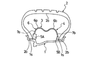
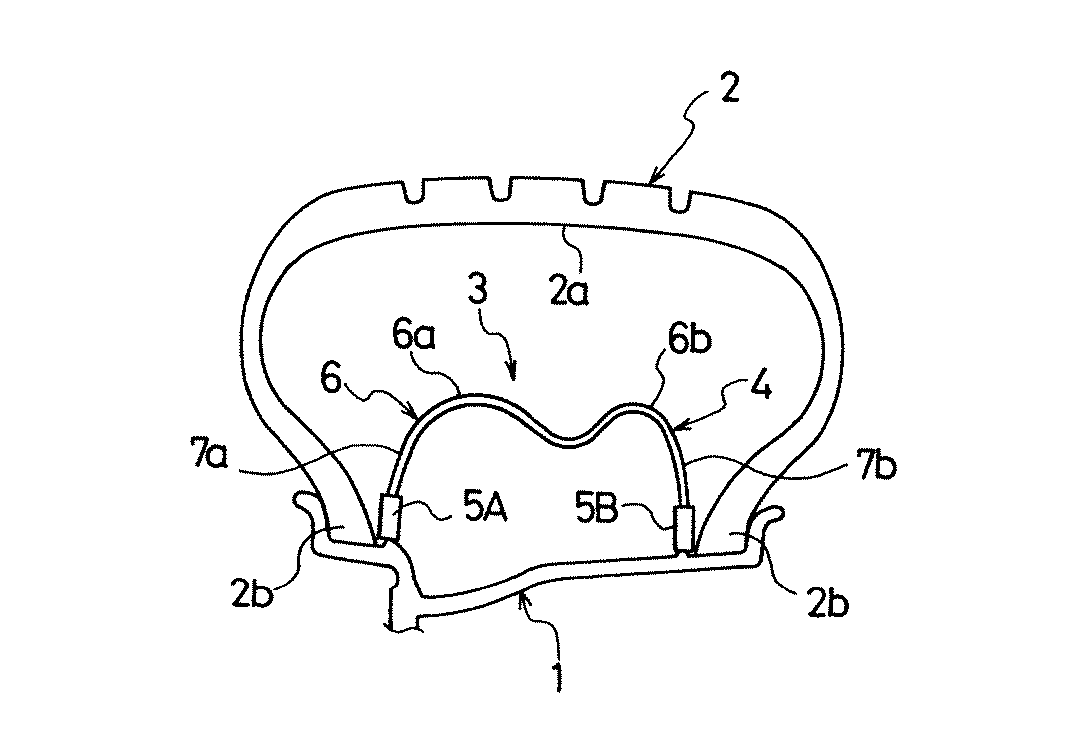
図1は本発明の一実施形態からなるタイヤ/ホイール組立体(車輪)の要部を示す子午線断面図である。
【0018】
1はホイール外周のリム、2は空気入りタイヤ、3はランフラット用支持体である。これらリム1、空気入りタイヤ2、ランフラット用支持体3は、図示しないホイールの回転軸を中心として共軸に環状に形成されている。
【0019】
ランフラット用支持体3は、金属、樹脂などの剛性材から形成された環状シェル4とゴム、弾性樹脂などの弾性材から形成された左右の弾性リング5A,5Bとから構成されている。
【0020】
環状シェル4は外周側に略同一の曲率半径を有する2個の凸曲面6a,6bをシェル幅方向においてもつ支持面6を形成し、その支持面6は空気入りタイヤ2が正常なときは空気入りタイヤ2の内面2aから離間しているが、パンクしたとき潰れたタイヤを支持するようになっている。また、環状シェル4の内周側は両側壁がそれぞれ脚部7a,7bとして二股状に開脚し、その内周側に弾性リング5A,5Bを取り付けている。
【0021】
弾性リング5A,5Bは剛性を左右で異ならせており、ランフラット走行時に負荷が大きく作用する、車両装着時に車両外側となる弾性リング5Aの剛性を、車両内側となる弾性リング5Bの剛性より大きくしてある。弾性リング5Aの剛性を高くする手法としては、図示するように、リング厚みを弾性リング5Bより厚くしたり、あるいは弾性リング5Bより高い弾性率の弾性材料を使用したり、また両者を組み合わせたりすることなどにより行うことができる。
【0022】
このように弾性リング5A,5Bが形成されたランフラット用支持体3は、リム組み時に、空気入りタイヤ2の内側に挿入され、弾性リング5A,5Bを空気入りタイヤ2のビード部2b,2bと共にリム1のリムシート1s,1sに同時に装着するようになっている。
【0023】
タイヤ/ホイール組立体がランフラット走行する時、ランフラット用支持体3の弾性リング5A,5Bにかかる負荷は、通常、車両外側の弾性リング5Aの方に大きく作用するが、上述した本発明のタイヤ/ホイール組立体では、その負荷の大きい車両外側となる弾性リング5Aの剛性を大きくしたので、耐久性を改善することができる。
【0024】
図1の実施形態では、環状シェル4の支持面6が2個の凸曲面6a,6bを有する場合を例示したが、この凸曲面の数は2個に限定されるものでなく、1個あるいは3個以上であってもよい。
【0025】
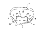
図2は、本発明のタイヤ/ホイール組立体の他の例を示し、この実施形態では、環状シェル4の支持面6をシェル幅方向において曲率半径の異なる2個の凸曲面6a,6bを有するように構成したものである。
【0026】
このようなランフラット用支持体3を使用したタイヤ/ホイール組立体では、曲率半径の小さい方の凸曲面6b側に位置する弾性リング5Bの剛性を曲率半径の大きい方の凸曲面6a側に位置する弾性リング5Aの剛性より大きくなるようにする。
【0027】
図2の構成のタイヤ/ホイール組立体では、ランフラット走行時に、ランフラット用支持体3の弾性リング5A,5Bにかかる負荷は、曲率半径の小さい方の凸曲面6b側に位置する弾性リング5Bの方に大きく作用するので、上記のように弾性リング5Bの剛性を大きくすることで、耐久性を向上することができる。
【0028】
図示する例では、リング厚みを同じにした弾性リング5A,5Bにおいて、弾性リング5Bに弾性リング5Aより高い弾性率の弾性材料を使用した場合を示すが、上述と同様に、リング厚みを弾性リング5Aより厚くしたり、あるいは両者を組み合わせたりすることなどにより、弾性リング5Bの剛性を弾性リング5Aの剛性より高くすることができる。
【0029】
図2の実施形態では、環状シェル4の支持面6が2個の凸曲面6a,6bを有する場合を例示したが、この凸曲面の数は3個以上あってもよく、少なくとも2個の凸曲面6a,6bを有する支持面6を備えた環状シェル4であればよい。
【0030】
本発明において、上記のようにランフラット走行時に負荷が大きく作用する弾性リングの方の剛性を大きくする場合、他方の弾性リングより剛性が10〜100%高くなるようにするのがよい。10%より低いと、耐久性を効果的に改善することが難しくなる。逆に100%を超えると、リング厚みを大きくした場合には重量の増加が大きくなり、高い弾性率の弾性材料を使用した場合には、脆くなり、リム組み時の変形に耐えられなくなる恐れがある。
【0031】
なお、本発明における弾性リングの剛性は、環状シェルを除去(環状シェルの脚部内周端部が弾性リング内に埋設されている場合には、脚部をその切断面が弾性リングの外周面と面一となるように切断して除去)した弾性リングをリング周方向に沿って1 0mmの長さで切り出し、室温時にてそのサンプルにリング径方向の荷重(2kgf )Wを付与(サンプルをリング内周面側を下側にして水平な平坦試験面上に載置し、サンプルの上面(リング外周面)全面に接触するようにした2kgf の重りをサンプル上に加える)した時のリング径方向における撓み量δ(mm)を測定し、W/δから得られた値を弾性リングの剛性とする。
【0032】
【実施例】
タイヤサイズを205/55R16、リムサイズを16×6 1/2JJで共通にし、車両装着時に車両外側となる弾性リングの剛性を、車両内側となる弾性リングの剛性より大きくした図1に示す構成の本発明のタイヤ/ホイール組立体(実施例)と、本発明のタイヤ/ホイール組立体において、車両外側となる弾性リングの剛性を車両内側となる弾性リングと同じにした従来のタイヤ/ホイール組立体(従来例)をそれぞれ作製した。
【0033】
両試験タイヤ/ホイール組立体の弾性リングはゴムから構成され、本発明のタイヤ/ホイール組立体における車両外側となる弾性リングの剛性は、車両内側となる弾性リングの剛性より30%大きくなっている。
【0034】
これら各試験タイヤ/ホイール組立体を以下に示す測定方法により、耐久性の評価試験を行ったところ、表1に示す結果を得た。
耐久性
各試験タイヤ/ホイール組立体を空気圧0kPa の状態で排気量2.5リットルの前輪駆動車の前右輪に装着し、時速90kmで周回路を左回りに走行した際に、走行不能になった距離を測定し、その結果を従来のタイヤ/ホイール組立体を100とする指数値で評価した。この値が大きい程、耐久性が優れている。
【0035】
なお、前輪駆動車の前右輪以外には、上記同じサイズのタイヤとリムを使用し、その空気圧は200kPa にした。
【0036】
【表1】
【0037】
【発明の効果】
上述したように本発明は、左右の弾性リングの剛性をランフラット走行時に負荷が大きく作用する弾性リングの方が大きくなるように左右で異ならせたので、耐久性を向上することができる。
【図面の簡単な説明】
【図1】本発明の実施形態からなるタイヤ/ホイール組立体の要部を示す子午線断面図である。
【図2】本発明の他の実施形態からなるタイヤ/ホイール組立体の要部を示す子午線断面図である。
【符号の説明】
1(ホイールの)リム 2 空気入りタイヤ
3 ランフラット用支持体 4 環状シェル
5A,5B 弾性リング 6 支持面
6a,6b 凸曲面 7a,7b 脚部[0001]
BACKGROUND OF THE INVENTION
The present invention relates to a tire / wheel assembly and a run-flat support, and more particularly, to a tire / wheel assembly and a run-flat support used for the tire / wheel assembly that are improved in durability.
[0002]
[Prior art]
Many technologies have been proposed in response to market demands that enable emergency traveling of several hundred km even when a pneumatic tire is punctured while the vehicle is traveling. Among these many proposals, the technique proposed in Japanese Patent Application Laid-Open No. 10-297226 and Japanese Patent Application Laid-Open No. 2001-519279 is a technique in which a support is mounted on a rim inside a hollow portion of a pneumatic tire assembled with a rim, The run flat running is made possible by supporting the punctured tire by the support.
[0003]
The run-flat support body includes an annular shell having an open leg structure in which an outer peripheral side is a support surface and an inner peripheral side is opened, and elastic rings are attached to both leg portions. And is supported on the rim. This run-flat support has the advantage that it can be used without disruption to the market because it can be used as is without any special modifications to existing wheels / rims.
[0004]
However, due to the structure of such a run-flat support, the elastic ring is more easily broken during run-flat travel than the annular shell, and the durability of the run-flat support greatly affects the durability of the elastic ring. Is done. Therefore, it is essential to improve the durability of the elastic ring in order to improve the durability of the tire / wheel assembly to which the run-flat support is mounted in the run-flat running.
[0005]
[Problems to be solved by the invention]
An object of the present invention is to provide a tire / wheel assembly and a run-flat support that can improve durability.
[0006]
[Means for Solving the Problems]
The tire / wheel assembly of the present invention that achieves the above object includes an annular shell having a support portion on an outer peripheral side and a bifurcated inner peripheral side in a hollow portion of a pneumatic tire mounted on a rim of a wheel. a tire / wheel assembly having a lateral run-flat support body consisting of an elastic ring arranged to support the legs and open leg to said forked on the rim, the rigidity of the elastic ring, and the vehicle outer side when mounted to a vehicle The rigidity of the elastic ring is larger than that of the elastic ring on the inside of the vehicle, and the rigidity of the elastic ring is obtained by cutting the elastic ring from which the annular shell is removed into a sample having a length of 10 mm along the ring circumferential direction. A deflection amount δ in the ring radial direction when a load W in the ring radial direction is applied to the sample is measured, and is a value obtained from W / δ .
Another tire / wheel assembly according to the present invention includes an annular shell in which a hollow portion of a pneumatic tire mounted on a wheel rim has an outer peripheral side as a supporting surface and an inner peripheral side is bifurcated, and the bifurcated shape. In a tire / wheel assembly in which a run-flat support body including left and right elastic rings for supporting a leg portion opened on a rim is disposed, the support surface of the annular shell has a different radius of curvature in the shell width direction. The left and right elastic rings have at least two convex curved surfaces, and the rigidity of the elastic ring located on the convex curved surface side with the smaller curvature radius is increased.
[0007]
Further, the run-flat support body of the present invention includes an annular shell having an outer peripheral side as a support surface and an inner peripheral side having a bifurcated leg and a leg portion having the bifurcated leg that is supported on the rim. In a run-flat support body comprising an elastic ring, the rigidity of the elastic ring is set so that the rigidity of the elastic ring on the vehicle outer side is larger than the rigidity of the elastic ring on the vehicle inner side when the vehicle is mounted. The elastic ring from which the annular shell has been removed is cut into a sample having a length of 10 mm along the ring circumferential direction, and a deflection amount δ in the ring radial direction when a load W in the ring radial direction is applied to the sample at room temperature is measured. It is a value obtained from W / δ .
The other run-flat support of the present invention has an annular shell having an outer peripheral side as a supporting surface and an inner peripheral side opened in a bifurcated shape, and a left and right support for supporting the leg portion opened in the bifurcated shape on a rim. In a run-flat support comprising an elastic ring, the support surface of the annular shell has at least two convex curved surfaces having different radii of curvature in the shell width direction, and the left and right elastic rings have a smaller radius of curvature. The rigidity of the elastic ring located on the convex curved surface side is increased.
[0008]
In this way, by increasing the rigidity of the elastic ring that is heavily loaded during run-flat running, the durability of the tire / wheel assembly equipped with the run-flat support body during run-flat running can be easily improved. it can.
[0009]
DETAILED DESCRIPTION OF THE INVENTION
In the present invention, the run-flat support is formed as an annular body that is inserted into the cavity of the pneumatic tire. The run-flat support body is formed smaller than the inner diameter of the hollow portion so that the outer diameter maintains a constant distance from the inner surface of the hollow portion of the pneumatic tire, and the inner diameter is substantially the same as the inner diameter of the bead portion of the pneumatic tire. Dimension is formed. The run-flat support body is assembled to a wheel together with the pneumatic tire while being inserted inside the pneumatic tire, thereby forming a tire / wheel assembly. If the pneumatic tire is punctured while the tire / wheel assembly is mounted on a vehicle, the punctured and crushed tire is supported on the outer peripheral surface of the run-flat support body. Enable.
[0010]
The run-flat support body includes an annular shell and an elastic ring as main parts.
[0011]
The annular shell forms a continuous support surface to support a tire that is punctured on the outer peripheral side (outer diameter side), and the inner peripheral side (inner diameter side) has a bifurcated shape with the left and right side walls as legs. Yes. The support surface on the outer peripheral side is formed so that the shape in a cross section orthogonal to the circumferential direction becomes a convex curved surface on the outer diameter side. The number of the convex curved surfaces arranged in the tire axial direction may be only one, but preferably two or more are arranged. By forming the support surface in such a manner that two or more convex curved surfaces are arranged in this manner, the contact portion of the support surface with respect to the tire inner surface (hollow portion inner surface) is dispersed to two or more to reduce local wear on the tire inner surface. In addition, it is possible to extend the running distance that enables run-flat running.
[0012]
The elastic rings are respectively attached to the ends of both leg portions that are bifurcated on the inner diameter side of the annular shell, and support the annular shell by abutting on the left and right rim seats. This elastic ring is made of rubber or elastic resin, and reduces the impact and vibration received by the annular shell from the punctured tire, and also prevents the rim seat from slipping to stably support the annular shell.
[0013]
Since the run-flat support must support the vehicle weight via the punctured tire, the annular shell is made of a rigid material. A metal, resin, or the like is used as the constituent material. Among these, steel, aluminum, etc. can be illustrated as a metal. Further, the resin may be either a thermoplastic resin or a thermosetting resin. Examples of the thermoplastic resin include nylon and polyester, and examples of the thermosetting resin include an epoxy resin and an unsaturated polyester resin. The resin may be used alone, or may be used as a fiber reinforced resin by blending reinforcing fibers.
[0014]
The elastic ring may be composed of any rubber or elastic resin as long as it can stably support the annular shell. For example, the rubber may be natural rubber, isoprene rubber, styrene-butadiene rubber, butadiene rubber, butyl rubber, etc. And a foamed resin such as polyurethane foam.
[0015]
The run-flat support used in the tire / wheel assembly of the present invention is based on the above-described configuration.
[0016]
Hereinafter, the present invention will be specifically described with reference to embodiments shown in the drawings.
[0017]
FIG. 1 is a meridian cross-sectional view showing a main part of a tire / wheel assembly (wheel) according to an embodiment of the present invention.
[0018]
Reference numeral 1 denotes a wheel rim, 2 is a pneumatic tire, and 3 is a run-flat support. The rim 1, the
[0019]
The run-
[0020]
The annular shell 4 forms a
[0021]
The
[0022]
The run-
[0023]
When the tire / wheel assembly is run flat, the load applied to the
[0024]
In the embodiment of FIG. 1, the case where the
[0025]
FIG. 2 shows another example of the tire / wheel assembly of the present invention. In this embodiment, the
[0026]
In a tire / wheel assembly using such a run-
[0027]
In the tire / wheel assembly having the configuration shown in FIG. 2, the load applied to the
[0028]
In the illustrated example, in the
[0029]
In the embodiment of FIG. 2, the case where the
[0030]
In the present invention, as described above, when the rigidity of the elastic ring on which the load acts greatly during run-flat traveling is increased, the rigidity is preferably 10 to 100% higher than that of the other elastic ring. If it is lower than 10%, it is difficult to effectively improve the durability. Conversely, if it exceeds 100%, the increase in weight increases when the ring thickness is increased, and if an elastic material with a high elastic modulus is used, it becomes brittle and may not be able to withstand the deformation during rim assembly. is there.
[0031]
The rigidity of the elastic ring in the present invention is determined by removing the annular shell (when the inner peripheral end of the leg of the annular shell is embedded in the elastic ring, the leg is cut off from the outer peripheral surface of the elastic ring. The elastic ring cut and removed so as to be flush with each other is cut out to a length of 10 mm along the circumferential direction of the ring, and a load (2 kgf) W in the radial direction of the ring is applied to the sample at room temperature. Ring radial direction when a 2kgf weight placed on the horizontal flat test surface with the inner peripheral side facing down and touching the entire upper surface of the sample (ring outer peripheral surface) is added to the sample) Is measured, and the value obtained from W / δ is defined as the rigidity of the elastic ring.
[0032]
【Example】
A book having a configuration shown in FIG. 1 in which the tire size is 205 / 55R16, the rim size is 16 × 6 1 / 2JJ, and the rigidity of the elastic ring on the outside of the vehicle is larger than the rigidity of the elastic ring on the inside of the vehicle when the vehicle is mounted. In the tire / wheel assembly of the invention (Example) and the tire / wheel assembly of the present invention, the rigidity of the elastic ring on the vehicle outer side is the same as that of the elastic ring on the vehicle inner side ( Conventional examples) were prepared.
[0033]
The elastic rings of both test tire / wheel assemblies are made of rubber, and the rigidity of the elastic ring on the vehicle outer side in the tire / wheel assembly of the present invention is 30% larger than the rigidity of the elastic ring on the vehicle inner side. .
[0034]
When each of these test tire / wheel assemblies was subjected to a durability evaluation test by the measurement method shown below, the results shown in Table 1 were obtained.
Durability Each test tire / wheel assembly is mounted on the front right wheel of a 2.5-liter front-wheel drive vehicle with an air pressure of 0 kPa, making it impossible to run when running counterclockwise at 90 km / h The measured distance was measured, and the result was evaluated by an index value with a conventional tire / wheel assembly as 100. The greater this value, the better the durability.
[0035]
In addition to the front right wheel of the front wheel drive vehicle, the same size tire and rim were used, and the air pressure was 200 kPa.
[0036]
[Table 1]
[0037]
【The invention's effect】
As described above, according to the present invention, the rigidity of the left and right elastic rings is varied between the left and right so that the elastic ring on which the load acts more greatly during run-flat travel is increased, so that the durability can be improved.
[Brief description of the drawings]
FIG. 1 is a meridian cross-sectional view showing a main part of a tire / wheel assembly according to an embodiment of the present invention.
FIG. 2 is a meridian cross-sectional view showing a main part of a tire / wheel assembly according to another embodiment of the present invention.
[Explanation of symbols]
DESCRIPTION OF SYMBOLS 1 (Wheel) rim 2
Claims (6)
前記弾性リングの剛性を、車両装着時に車両外側となる弾性リングの剛性を車両内側となる弾性リングの剛性より大きくし、
前記弾性リングの剛性は、環状シェルを除去した弾性リングをリング周方向に沿って10mmの長さのサンプルに切り出し、室温でそのサンプルにリング径方向の荷重Wを付与した時のリング径方向における撓み量δを測定し、W/δから得られる値であるタイヤ/ホイール組立体。A hollow portion of a pneumatic tire mounted on a rim of a wheel supports an annular shell having an outer peripheral side as a supporting surface and an inner peripheral side having a bifurcated leg and a leg portion having the bifurcated leg on the rim. In a tire / wheel assembly in which a run-flat support body including left and right elastic rings is arranged,
The rigidity of the elastic ring is larger than the rigidity of the elastic ring on the vehicle inner side when the vehicle is mounted,
The rigidity of the elastic ring is determined by cutting the elastic ring from which the annular shell has been removed into a sample having a length of 10 mm along the circumferential direction of the ring and applying a load W in the ring radial direction to the sample at room temperature. A tire / wheel assembly in which a deflection amount δ is measured and is obtained from W / δ .
前記弾性リングの剛性を、車両装着時に車両外側となる弾性リングの剛性を車両内側となる弾性リングの剛性より大きくし、The rigidity of the elastic ring is larger than the rigidity of the elastic ring on the vehicle inner side when the vehicle is mounted,
前記弾性リングの剛性は、環状シェルを除去した弾性リングをリング周方向に沿って10mmの長さのサンプルに切り出し、室温でそのサンプルにリング径方向の荷重Wを付与した時のリング径方向における撓み量δを測定し、W/δから得られる値であるランフラット用支持体。The rigidity of the elastic ring is determined by cutting the elastic ring from which the annular shell has been removed into a sample having a length of 10 mm along the circumferential direction of the ring and applying a load W in the ring radial direction to the sample at room temperature. A run-flat support, which is a value obtained by measuring the amount of deflection δ and obtaining from W / δ.
Priority Applications (3)
| Application Number | Priority Date | Filing Date | Title |
|---|---|---|---|
| JP2002212369A JP4108398B2 (en) | 2002-07-22 | 2002-07-22 | Tire / wheel assembly and run-flat support |
| US10/615,240 US6915824B2 (en) | 2002-07-22 | 2003-07-09 | Tire/wheel assembly and run-flat support member |
| DE10332847A DE10332847A1 (en) | 2002-07-22 | 2003-07-18 | Tire / wheel arrangement and supporting component for a flat wheel |
Applications Claiming Priority (1)
| Application Number | Priority Date | Filing Date | Title |
|---|---|---|---|
| JP2002212369A JP4108398B2 (en) | 2002-07-22 | 2002-07-22 | Tire / wheel assembly and run-flat support |
Publications (2)
| Publication Number | Publication Date |
|---|---|
| JP2004051003A JP2004051003A (en) | 2004-02-19 |
| JP4108398B2 true JP4108398B2 (en) | 2008-06-25 |
Family
ID=30437608
Family Applications (1)
| Application Number | Title | Priority Date | Filing Date |
|---|---|---|---|
| JP2002212369A Expired - Fee Related JP4108398B2 (en) | 2002-07-22 | 2002-07-22 | Tire / wheel assembly and run-flat support |
Country Status (3)
| Country | Link |
|---|---|
| US (1) | US6915824B2 (en) |
| JP (1) | JP4108398B2 (en) |
| DE (1) | DE10332847A1 (en) |
Families Citing this family (4)
| Publication number | Priority date | Publication date | Assignee | Title |
|---|---|---|---|---|
| JP4079714B2 (en) * | 2002-07-25 | 2008-04-23 | 横浜ゴム株式会社 | Run flat tire and tire wheel assembly |
| JP3803096B2 (en) * | 2003-08-26 | 2006-08-02 | 横浜ゴム株式会社 | Tire wheel assembly |
| JP4442165B2 (en) | 2003-09-04 | 2010-03-31 | 横浜ゴム株式会社 | Tire / wheel assembly and run-flat support |
| JP4492325B2 (en) * | 2004-12-03 | 2010-06-30 | トヨタ自動車株式会社 | Run flat tire |
Family Cites Families (5)
| Publication number | Priority date | Publication date | Assignee | Title |
|---|---|---|---|---|
| DE19707090A1 (en) | 1997-02-24 | 1998-08-27 | Continental Ag | Pneumatic vehicle wheel |
| DE19745409C2 (en) * | 1997-10-15 | 2002-06-20 | Continental Ag | Vehicle wheel with an emergency running support body |
| DE19825311C1 (en) * | 1998-06-05 | 2000-02-24 | Continental Ag | Vehicle wheel with an emergency running support body |
| DE19955832A1 (en) | 1999-11-20 | 2001-05-31 | Continental Ag | Vehicle wheel with an emergency running support body |
| JP4076388B2 (en) * | 2002-07-18 | 2008-04-16 | 横浜ゴム株式会社 | Tire / wheel assembly and run-flat support |
-
2002
- 2002-07-22 JP JP2002212369A patent/JP4108398B2/en not_active Expired - Fee Related
-
2003
- 2003-07-09 US US10/615,240 patent/US6915824B2/en not_active Expired - Fee Related
- 2003-07-18 DE DE10332847A patent/DE10332847A1/en not_active Withdrawn
Also Published As
| Publication number | Publication date |
|---|---|
| JP2004051003A (en) | 2004-02-19 |
| US6915824B2 (en) | 2005-07-12 |
| US20040011447A1 (en) | 2004-01-22 |
| DE10332847A1 (en) | 2004-02-12 |
Similar Documents
| Publication | Publication Date | Title |
|---|---|---|
| JP2005280459A (en) | Run flat tire | |
| JP4108398B2 (en) | Tire / wheel assembly and run-flat support | |
| JP4039907B2 (en) | Run flat tire and tire wheel assembly | |
| JP4039909B2 (en) | Tire wheel assembly and run-flat support | |
| JP4079710B2 (en) | Tire wheel assembly and run-flat support | |
| JP4076388B2 (en) | Tire / wheel assembly and run-flat support | |
| JP4183030B2 (en) | Tire / wheel assembly | |
| CN1328073C (en) | Tire/wheel assembly | |
| JP4076387B2 (en) | Tire / wheel assembly and run-flat support | |
| JP3952179B2 (en) | Tire wheel assembly | |
| JP4039906B2 (en) | Tire wheel assembly and run-flat support | |
| JP4145105B2 (en) | Tire wheel assembly and run-flat support | |
| JP3952177B2 (en) | Tire / wheel assembly and run-flat support | |
| JP4442165B2 (en) | Tire / wheel assembly and run-flat support | |
| JP4079709B2 (en) | Tire wheel assembly and run-flat support | |
| JP4187094B2 (en) | Automobile wheel with emergency running support and emergency running support | |
| JP4145099B2 (en) | Tire wheel assembly and run-flat support | |
| JP4039902B2 (en) | Tire / wheel assembly and run-flat support | |
| JP4222796B2 (en) | Tire / wheel assembly | |
| JP3952183B2 (en) | Tire wheel assembly and run-flat support | |
| JP4367908B2 (en) | Tire wheel assembly and run-flat support | |
| JP4183031B2 (en) | Tire / wheel assembly | |
| JP4205381B2 (en) | Tire / wheel assembly | |
| JP4222818B2 (en) | Tire wheel assembly | |
| JP3803096B2 (en) | Tire wheel assembly |
Legal Events
| Date | Code | Title | Description |
|---|---|---|---|
| A621 | Written request for application examination |
Free format text: JAPANESE INTERMEDIATE CODE: A621 Effective date: 20050614 |
|
| A977 | Report on retrieval |
Free format text: JAPANESE INTERMEDIATE CODE: A971007 Effective date: 20071022 |
|
| A131 | Notification of reasons for refusal |
Free format text: JAPANESE INTERMEDIATE CODE: A131 Effective date: 20071030 |
|
| A521 | Written amendment |
Free format text: JAPANESE INTERMEDIATE CODE: A523 Effective date: 20071207 |
|
| A131 | Notification of reasons for refusal |
Free format text: JAPANESE INTERMEDIATE CODE: A131 Effective date: 20080115 |
|
| A521 | Written amendment |
Free format text: JAPANESE INTERMEDIATE CODE: A523 Effective date: 20080218 |
|
| TRDD | Decision of grant or rejection written | ||
| A01 | Written decision to grant a patent or to grant a registration (utility model) |
Free format text: JAPANESE INTERMEDIATE CODE: A01 Effective date: 20080325 |
|
| A61 | First payment of annual fees (during grant procedure) |
Free format text: JAPANESE INTERMEDIATE CODE: A61 Effective date: 20080402 |
|
| FPAY | Renewal fee payment (event date is renewal date of database) |
Free format text: PAYMENT UNTIL: 20110411 Year of fee payment: 3 |
|
| R150 | Certificate of patent or registration of utility model |
Free format text: JAPANESE INTERMEDIATE CODE: R150 |
|
| LAPS | Cancellation because of no payment of annual fees |