JP4108317B2 - Code conversion method and apparatus, program, and storage medium - Google Patents
Code conversion method and apparatus, program, and storage medium Download PDFInfo
- Publication number
- JP4108317B2 JP4108317B2 JP2001346987A JP2001346987A JP4108317B2 JP 4108317 B2 JP4108317 B2 JP 4108317B2 JP 2001346987 A JP2001346987 A JP 2001346987A JP 2001346987 A JP2001346987 A JP 2001346987A JP 4108317 B2 JP4108317 B2 JP 4108317B2
- Authority
- JP
- Japan
- Prior art keywords
- adaptive codebook
- code
- delay
- codebook delay
- signal
- Prior art date
- Legal status (The legal status is an assumption and is not a legal conclusion. Google has not performed a legal analysis and makes no representation as to the accuracy of the status listed.)
- Expired - Fee Related
Links
- 238000000034 method Methods 0.000 title claims description 348
- 238000006243 chemical reaction Methods 0.000 title claims description 305
- 230000003044 adaptive effect Effects 0.000 claims description 1410
- 230000005284 excitation Effects 0.000 claims description 655
- 230000008569 process Effects 0.000 claims description 157
- 238000004364 calculation method Methods 0.000 claims description 125
- 238000012545 processing Methods 0.000 claims description 90
- 230000015572 biosynthetic process Effects 0.000 claims description 87
- 238000003786 synthesis reaction Methods 0.000 claims description 87
- 230000001934 delay Effects 0.000 claims description 80
- 230000005236 sound signal Effects 0.000 claims description 60
- 230000004044 response Effects 0.000 claims description 52
- 238000000926 separation method Methods 0.000 claims description 43
- 230000006978 adaptation Effects 0.000 claims description 22
- 230000000717 retained effect Effects 0.000 claims description 15
- 230000003595 spectral effect Effects 0.000 claims description 12
- 238000013139 quantization Methods 0.000 claims description 10
- 238000010586 diagram Methods 0.000 description 45
- 230000006870 function Effects 0.000 description 6
- 238000012546 transfer Methods 0.000 description 6
- 230000002159 abnormal effect Effects 0.000 description 5
- 238000010561 standard procedure Methods 0.000 description 4
- 238000004891 communication Methods 0.000 description 3
- 238000007796 conventional method Methods 0.000 description 3
- 239000013598 vector Substances 0.000 description 3
- 230000000694 effects Effects 0.000 description 2
- 238000001914 filtration Methods 0.000 description 2
- 238000001228 spectrum Methods 0.000 description 2
- 238000004590 computer program Methods 0.000 description 1
- 238000012937 correction Methods 0.000 description 1
- 238000012986 modification Methods 0.000 description 1
- 230000004048 modification Effects 0.000 description 1
- 238000010606 normalization Methods 0.000 description 1
- 238000005070 sampling Methods 0.000 description 1
- 238000010187 selection method Methods 0.000 description 1
Images


Classifications
-
- G—PHYSICS
- G10—MUSICAL INSTRUMENTS; ACOUSTICS
- G10L—SPEECH ANALYSIS TECHNIQUES OR SPEECH SYNTHESIS; SPEECH RECOGNITION; SPEECH OR VOICE PROCESSING TECHNIQUES; SPEECH OR AUDIO CODING OR DECODING
- G10L19/00—Speech or audio signals analysis-synthesis techniques for redundancy reduction, e.g. in vocoders; Coding or decoding of speech or audio signals, using source filter models or psychoacoustic analysis
- G10L19/04—Speech or audio signals analysis-synthesis techniques for redundancy reduction, e.g. in vocoders; Coding or decoding of speech or audio signals, using source filter models or psychoacoustic analysis using predictive techniques
- G10L19/16—Vocoder architecture
- G10L19/173—Transcoding, i.e. converting between two coded representations avoiding cascaded coding-decoding
-
- G—PHYSICS
- G10—MUSICAL INSTRUMENTS; ACOUSTICS
- G10L—SPEECH ANALYSIS TECHNIQUES OR SPEECH SYNTHESIS; SPEECH RECOGNITION; SPEECH OR VOICE PROCESSING TECHNIQUES; SPEECH OR AUDIO CODING OR DECODING
- G10L19/00—Speech or audio signals analysis-synthesis techniques for redundancy reduction, e.g. in vocoders; Coding or decoding of speech or audio signals, using source filter models or psychoacoustic analysis
- G10L19/04—Speech or audio signals analysis-synthesis techniques for redundancy reduction, e.g. in vocoders; Coding or decoding of speech or audio signals, using source filter models or psychoacoustic analysis using predictive techniques
- G10L19/08—Determination or coding of the excitation function; Determination or coding of the long-term prediction parameters
-
- G—PHYSICS
- G10—MUSICAL INSTRUMENTS; ACOUSTICS
- G10L—SPEECH ANALYSIS TECHNIQUES OR SPEECH SYNTHESIS; SPEECH RECOGNITION; SPEECH OR VOICE PROCESSING TECHNIQUES; SPEECH OR AUDIO CODING OR DECODING
- G10L19/00—Speech or audio signals analysis-synthesis techniques for redundancy reduction, e.g. in vocoders; Coding or decoding of speech or audio signals, using source filter models or psychoacoustic analysis
- G10L2019/0001—Codebooks
- G10L2019/0011—Long term prediction filters, i.e. pitch estimation
Landscapes
- Engineering & Computer Science (AREA)
- Computational Linguistics (AREA)
- Signal Processing (AREA)
- Health & Medical Sciences (AREA)
- Audiology, Speech & Language Pathology (AREA)
- Human Computer Interaction (AREA)
- Physics & Mathematics (AREA)
- Acoustics & Sound (AREA)
- Multimedia (AREA)
- Compression, Expansion, Code Conversion, And Decoders (AREA)
- Transmission Systems Not Characterized By The Medium Used For Transmission (AREA)
Description
【0001】
【発明の属する技術分野】
本発明は、音声信号を低ビットレートで伝送あるいは蓄積するための符号化および復号技術に関し、特に、異なる符号化復号方式を用いて音声通信を行うに際し、音声をある方式により符号化して得た符号を、他の方式により復号可能な符号に高音質かつ低演算量で変換する、符号変換方法および装置ならびにプログラムと記録媒体に関する。
【0002】
【従来の技術】
音声信号を中低ビットレートで高能率に符号化する方法として、音声信号を、線形予測(Linear Prediction: LP)フィルタと、このフィルタを駆動する励振信号とに分離して符号化する方法が広く用いられている。その代表的な方法の一つとして、Code Excited Linear Prediction(符号励振線形予測、「CELP」と略記される)がある。CELPでは、入力音声の周波数特性を表す線形予測係数が設定された線形予測フィルタを、入力音声のピッチ周期を表す適応コードブック(Adaptive Codebook: 「ACB」と略記される)と、乱数やパルスから成る固定コードブック(Fixed Codebook: 「FCB」と略記される)との和で表される励振信号により駆動することで、合成音声信号が得られる。このとき、ACB成分とFCB成分には、それぞれゲイン、すなわちACBゲインとFCBゲインを乗ずる。なお、CELPに関しては、M.R.SchroederとB.S.Atal氏による「Code excited linear prediction: High quality speech at very low bit rates」と題する論文(Proc. Of IEEE Int. Conf. On Acoust., Speech and Signal Processing, pp.937-940, 1985)(以下「文献1」という)が参照される。
【0003】
ところで、例えば3G(第3世代)移動体網と有線パケット網間の相互接続を想定した場合、各網で用いられる標準音声符号化方式が異なるため、直接接続できない、という問題がある。
【0004】
これに対する最も簡単な解法は、タンデム接続である。しかしながら、タンデム接続では、一方の標準方式を用いて音声を符号化して得た符号列から、その標準方式を用いて、音声信号を一旦復号し、この復号された音声信号を、他方の標準方式を用いて、再度符号化を行う。
【0005】
このため、タンデム接続は、各音声符号化復号方式で符号化と復号を一度だけ行う場合に比べて、一般に音質の低下、遅延の増加、計算量の増加を招く、という問題がある。
【0006】
これに対して、一方の標準方式を用いて音声を符号化して得た符号を、他方の標準方式により復号可能な符号に、符号領域または符号化パラメータ領域で変換する符号変換方式は、前述の問題に対して有効である。
【0007】
符号を変換する方法については、Hong-Goo Kangらによる「Improving Transcoding Capability of Speech Coders in Clean and Frame Erasured Channel Environments」と題する論文(Proc. Of IEEE Workshop on Speech Coding 2000, pp.78-80, 2000)(以下、「文献2」という)が参照される。
【0008】
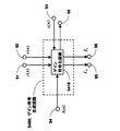
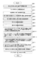
図26は、第1の音声符号化方式(「方式A」という)を用いて音声を符号化して得た符号を、第2の方式(「方式B」という)により復号可能な符号に変換する、符号変換装置の構成の一例を示す図である。図26を参照すると、符号分離回路1010で分離された方式AのLP係数符号、ACB符号、FCB符号、ゲイン符号をそれぞれ入力し方式BのLP係数符号、ACB符号、FCB符号、ゲイン符号をそれぞれ符号多重回路1020に出力するLP係数符号変換回路100、ACB符号変換回路200、FCB符号変換回路300、ゲイン符号変換回路400を備えている。
【0009】
方式Aにおいて、線形予測係数の符号化は、T(A)fr msec周期(フレーム)毎に行われ、ACB、FCBおよびゲインなど励振信号の構成要素の符号化は、T(A)sfr=T(A)fr /N(A)sfr msec周期(サブフレーム)毎に行われるものとする。
【0010】
一方、方式Bにおいては、線形予測係数の符号化は、T(B)fr msec周期(フレーム)毎に行われ、励振信号の構成要素の符号化は、T(B)sfr=T(B)fr/N( B )sfr msec周期(サブフレーム)毎に行われるものとする。
【0011】
また、方式Aのフレーム長、サブフレーム数、およびサブフレーム長を各々、
L(A)fr、N(A)sfr、およびL(A)sfr=L(A)fr/N(A)sfrとする。
【0012】
方式Bのフレーム長、サブフレーム数およびサブフレーム長を各々、
L(B)fr、N(B)sfr、およびL(B)sfr=L(B)fr/N(B)sfrとする。
【0013】
以下の説明では、簡単のため、
L(A)fr=L(B)fr、
N(A)sfr=N(B)sfr=2、
L(A)sfr=L(B)sfr
とする。
【0014】
ここで、例えば、サンプリング周波数を8000Hz(8KHz)とし、T(A)frおよびT(B)frを10msecとすれば、L(A)frおよびL(B)frは160サンプルとなり、L(A)sfrおよびL(B)sfrは80サンプルとなる。
【0015】
図26を参照して、従来の符号変換装置の各構成要素について説明する。
【0016】
入力端子10から、方式Aにより音声を符号化して得た第1の符号列を入力する。
【0017】
符号分離回路1010は、入力端子10から入力した第1の符号列(多重化された信号)から、線形予測係数(LP係数)、ACB、FCB、ACBゲインおよびFCBゲインに対応する符号、すなわちLP係数符号、ACB符号、FCB符号、ゲイン符号を分離する。
【0018】
ここで、ACBゲインとFCBゲインは、まとめて符号化及び復号されるものとし、簡単のため、これを「ゲイン」と呼び、その符号を「ゲイン符号」と呼ぶことにする。
【0019】
また、LP係数符号、ACB符号、FCB符号、ゲイン符号を、それぞれ「第1のLP係数符号」、「第1のACB符号」、「第1のFCB符号」、「第1のゲイン符号」と呼ぶことにする。
【0020】
そして、第1のLP係数符号をLP係数符号変換回路100へ出力し、第1のACB符号をACB符号変換回路200へ出力し、第1のFCB符号をFCB符号変換回路300へ出力し、第1のゲイン符号をゲイン符号変換回路400へ出力する。
【0021】
LP係数符号変換回路100は、符号分離回路1010から出力される第1のLP係数符号を入力し、第1のLP係数符号を方式Bにより復号可能な符号に変換する。この変換されたLP係数符号を、第2のLP係数符号として符号多重回路1020へ出力する。
【0022】
ACB符号変換回路200は、符号分離回路1010から出力される第1のACB符号を入力し、第1のACB符号を方式Bにより復号可能な符号に変換する。この変換されたACB符号を、第2のACB符号として符号多重回路1020へ出力する。
【0023】
FCB符号変換回路300は、符号分離回路1010から出力される第1のFCB符号を入力し、第1のFCB符号を方式Bにより復号可能な符号に変換する。この変換されたFCB符号を、第2のFCB符号として符号多重回路1020へ出力する。
【0024】
ゲイン符号変換回路400は、符号分離回路1010から出力される第1のゲイン符号を入力し、第1のゲイン符号を方式Bにより復号可能な符号に変換する。この変換されたゲイン符号を、第2のゲイン符号として符号多重回路1020へ出力する。
【0025】
各変換回路のより具体的な動作を以下に説明する。
【0026】
LP係数符号変換回路100は、符号分離回路1010から入力した第1のLP係数符号を、方式AにおけるLP係数復号方法により復号して、第1のLP係数を得る。次に、LP係数符号変換回路100は、第1のLP係数を、方式BにおけるLP係数の量子化方法および符号化方法により量子化および符号化して第2のLP係数符号を得る。そして、LP係数符号変換回路100は、これを方式BにおけるLP係数復号方法により復号可能な符号として符号多重回路1020へ出力する。
【0027】
ACB符号変換回路200は、符号分離回路1010から入力した第1のACB符号を、方式Aにおける符号と方式Bにおける符号との対応関係を用いて読み替えることにより、第2のACB符号を得る。そして、ACB符号変換回路200は、第2のACB符号を、方式BにおけるACB復号方法により復号可能な符号として、符号多重回路1020へ出力する。
【0028】
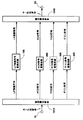
ここで、図27を参照して、符号の読み替えについて説明する。例えば、方式AにおけるACB符号i(A) Tが「56」のとき、これに対応するACB遅延T(A)が「76」であるとする。方式Bでは、ACB符号i(B) Tが「53」のとき、これに対応するACB遅延T(B)が「76」であるとすると、ACB遅延の値が同一(この場合では76)となるように、方式Aから方式BへとACB符号を変換するには、方式AにおけるACB符号「56」を方式BにおけるACB符号「53」に対応付ければよい。以上により、符号の読み替えについての説明を終え、再び図26の説明に戻る。
【0029】
FCB符号変換回路300は、符号分離回路1010から入力した第1のFCB符号を、方式Aにおける符号と方式Bにおける符号との対応関係を用いて読み替えることにより、第2のFCB符号を得る。そして、これを方式BにおけるFCB復号方法により復号可能な符号として符号多重回路1020へ出力する。ここで、符号の読み替えは、前述したACB符号の変換におけるそれと同様の方法で実現できる。あるいは、後述するLP係数符号の変換と同様の方法で実現することもできる。
【0030】
ゲイン符号変換回路400は、符号分離回路1010から入力した第1のゲイン符号を、方式Aにおけるゲイン復号方法により復号して、第1のゲインを得る。次に、ゲイン符号変換回路400は、前記第1のゲインを、方式Bにおけるゲインの量子化方法および符号化方法により量子化および符号化して第2のゲイン符号を得る。そして、ゲイン符号変換回路400は、第2のゲイン符号を方式Bにおけるゲイン復号方法により復号可能な符号として符号多重回路1020へ出力する。ここで、ゲイン符号の変換はLP係数符号の変換と同様の方法で実現できるため、以下では簡単のため、LP係数符号の変換のみに着目し、これを詳細に説明する。
【0031】
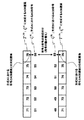
図28を参照して、LP係数符号変換回路100の各構成要素について説明する。
【0032】
前述のITU-T標準G.729など多くの標準方式では、LP係数を線スペクトル対(Line Spectral Pair: 「LSP」と略記される)で表現し、LSPを符号化および復号することが多いため、以下、LP係数はLSPにより表現されているものとする。
【0033】
ここで、LP係数からLSPへの変換、およびLSPからLP係数への変換については、周知の方法、例えば、「Coding of Speech at 8 kbit/s using Conjugate-Structure Algebraic-Code-Excited Linear-Prediction (CS-ACELP)」(ITU-T Recommendation G.729)(「文献3」という)の第3.2.3節および第3.2.6節の記載が参照される。
【0034】
LP係数復号回路110は、LP係数符号から対応するLSPを復号する。LP係数復号回路110は、複数セットのLSPが格納された第1のLSPコードブック111を備えており、符号分離回路1010から出力される第1のLP係数符号を、入力端子31を介して入力し、第1のLP係数符号に対応するLSPを前記第1のLSPコードブック111より読み出し、読み出されたLSPを第1のLSPとしてLP係数符号化回路130へ出力する。ここで、LP係数符号からのLSPの復号は、方式AにおけるLP係数の復号方法(ここでは、LSPにより表現されているのでLSPの復号となる)に従い、方式AのLSPコードブックを用いる。
【0035】
LP係数符号化回路130は、LP係数復号回路110から出力される第1のLSPを入力し、複数セットのLSPが格納された第2のLSPコードブック131から第2のLSPとそれに対応するLP係数符号の各々を順次読み込み、第1のLSPとの誤差が最小となる第2のLSPを選択し、それに対応するLP係数符号を、第2のLP係数符号として出力端子32を介して符号多重回路1020へ出力する。ここで、第2のLSPの選択方法、すなわちLSPの量子化および符号化方法は、方式BにおけるLSPの量子化方法および符号化方法に従い、方式BのLSPコードブックを用いる。ここで、LSPの量子化および符号化については、例えば「文献3」の第3.2.4節の記載が参照される。
【0036】
以上により、LP係数符号変換回路100の説明を終え、再び図26の説明に戻る。
【0037】
符号多重回路1020は、LP係数符号変換回路100から出力される第2のLP係数符号と、ACB符号変換回路200から出力される第2のACB符号と、FCB符号変換回路300から出力される第2のFCB符号と、ゲイン符号変換回路400から出力される第2のゲイン符号を入力し、これらを多重化して得られる符号列を第2の符号列として出力端子20を介して出力する。以上で、図26の説明を終える。
【0038】
なお、上記した従来の符号変換装置に関連した装置として、例えば特開平8−146997号公報には、量子化値もしくは量子化方法が異なる符号化を行う第1の音声符号化方法と第2の音声符号化方法とがある場合に、第1の音声符号化方法による多重化符号を第2の音声符号化方法による多重化符号に変換する符号変換装置として、第1の音声符号化方法により符号化された多重化符号を符号分離部が入力し、各符号毎に分離し、符号分離部により分離された各々の符号を、第1の音声符号化方法による符号と、第2の音声符号化方法による符号との対応関係に従って第2の音声符号化方法による各々の符号に変換し、多重化部は変換部により変換された第2の音声符号化方法による各々の符号を多重化する構成が開示されている。
【0039】
【発明が解決しようとする課題】
しかしながら、図26等を参照して説明した従来の符号変換装置においては、ACB遅延に対応するACB符号を変換するに際して、符号変換後のACB符号から得られるACB遅延を用いて生成される方式Bの復号音声において異音を発生する場合がある、という問題点を有していることを本発明者は知見した。
【0040】
その理由は、方式Bにおいて、線形予測係数(LP係数)およびゲインとACB遅延との間に不整合を生じるからである。このことは、線形予測係数およびゲインに対応する符号の変換において、方式Bによる量子化が介在することによって、線形予測係数およびゲインの値が、方式Aと方式Bとでは異なるのに対し、上記従来の符号変換装置では、方式Aで求められたACB遅延を、方式BのACB遅延として直接用いることに起因する。
【0041】
したがって、本発明は、上記問題点に鑑みてなされたものであって、その主たる目的は、第1の方式から第2の方式への変換にあたり、ACB遅延に対応するACB符号を変換するに際して、符号変換後のACB符号から得られるACB遅延を用いて生成される第2の方式の復号音声における異音の発生を抑止できる装置および方法ならびにそのプログラムを記録した記録媒体を提供することにある。これ以外の本発明の目的、特徴、利点等は以下の説明から、当業者には直ちに明らかとされるであろう。
【0042】
【課題を解決するための手段】
前記目的を達成する、本願の第1の発明は、第1の符号列を、第2の符号列へ変換する符号変換方法において、前記第1の符号列から第1の線形予測係数と励振信号の情報を得て、前記第1の線形予測係数をもつフィルタを前記励振信号の情報から得られる励振信号で駆動することによって音声信号を生成するステップと、前記励振信号の情報に含まれる第1の適応コードブック遅延と前記音声信号を用いて第2の適応コードブック遅延を選択し、前記第2の適応コードブック遅延に対応する符号を第2の符号列における適応コードブック遅延の符号として出力するステップ、を含む、ことを特徴とする。
【0043】
本願の第2の発明は、第1の符号列を、第2の符号列へ変換する符号変換方法において、前記第1の符号列から第1の線形予測係数を得る第1のステップと、前記第1の符号列から励振信号の情報を得る第2のステップと、前記励振信号の情報から励振信号を得る第3のステップと、前記第1の線形予測係数をもつフィルタを前記励振信号により駆動することによって音声信号を生成する第4のステップと、前記励振信号の情報に含まれる第1の適応コードブック遅延を記憶保持する第5のステップと、前記第2の符号列における適応コードブック遅延の符号に対応する第2の適応コードブック遅延を記憶保持する第6のステップと、記憶保持されている前記第1の適応コードブック遅延と記憶保持されている前記第2の適応コードブック遅延とから探索範囲制御値を計算する第7のステップと、前記第1の適応コードブック遅延と前記探索範囲制御値により規定される範囲内にある遅延から前記音声信号を用いて第2の適応コードブック遅延を選択し、前記第2の適応コードブック遅延に対応する符号を第2の符号列における適応コードブック遅延の符号として出力する第8のステップ、を含むことを特徴とする。
【0044】
本願の第3の発明は、前記第2の発明における、前記第5のステップにおいて、符号列を変換する時間単位であるフレームを分割したサブフレーム毎に、前記第1の適応コードブック遅延を順次記憶し、あらかじめ定めたサブフレーム数分の前記第1の適応コードブック遅延を保持することと、前記第6のステップにおいて、前記サブフレーム毎に、前記第2の適応コードブック遅延を順次記憶し、あらかじめ定めたサブフレーム数分の前記第2の適応コードブック遅延を保持することと、前記第7のステップにおいて、記憶保持されている前記第1の適応コードブック遅延と記憶保持されている前記第2の適応コードブック遅延との差分の絶対値を、保持されている全ての前記第1の適応コードブック遅延および前記第2の適応コードブック遅延について同じサブフレームに対応するものどうしで計算し、前記絶対値に重み係数を乗じた値を前記サブフレーム数分について加算した値を、前記探索範囲制御値とすること、を特徴とする。
【0045】
本願の第4の発明は、第1の符号列を、第2の符号列へ変換する符号変換方法において、前記第1の符号列から第1の線形予測係数を得る第1のステップと、前記第1の符号列から励振信号の情報を得る第2のステップと、前記励振信号の情報から励振信号を得る第3のステップと、前記第1の線形予測係数をもつフィルタを前記励振信号により駆動することによって音声信号を生成する第4のステップと、符号列を変換する時間単位であるフレームを分割したサブフレーム毎に、前記励振信号の情報に含まれる第1の適応コードブック遅延を順次記憶し、あらかじめ定めたサブフレーム数分の前記第1の適応コードブック遅延を保持する第5のステップと、前記サブフレーム毎に、前記第2の符号列における適応コードブック遅延の符号に対応する第2の適応コードブック遅延を順次記憶し、あらかじめ定めたサブフレーム数分の前記第2の適応コードブック遅延を保持する第6のステップと、記憶保持されている前記第1の適応コードブック遅延と記憶保持されている前記第2の適応コードブック遅延との差分の絶対値を、保持されている全ての第1の適応コードブック遅延および第2の適応コードブック遅延について同じサブフレームに対応するものどうしで計算し、前記絶対値に重み係数を乗じた値を前記サブフレーム数分について加算した値を、探索範囲制御値とする第7のステップと、前記フレームにおける少なくとも一つのサブフレームにおいて、前記第1の適応コードブック遅延と前記探索範囲制御値により規定される範囲内にある遅延から前記音声信号を用いて第2の適応コードブック遅延を選択し、前記第2の適応コードブック遅延に対応する符号を第2の符号列における適応コードブック遅延の符号として出力する第8のステップと、前記フレームにおける少なくとも一つのサブフレームにおいて、前記第1の適応コードブック遅延とそれに対応する第1の遅延符号との関係と、前記第2の適応コードブック遅延とそれに対応する第2の遅延符号との関係とを利用して、前記第1の適応コードブック遅延を前記第2の適応コードブック遅延に対応付けることによって前記第1の遅延符号から前記第2の遅延符号への変換を行い、前記第2の遅延符号を第2の符号列における適応コードブック遅延の符号として出力する第9のステップ、を含むことを特徴とする。
【0046】
本願の第5の発明は、第1の符号列を、第2の符号列へ変換する符号変換方法において、前記第1の符号列から第1の線形予測係数を得る第1のステップと、前記第1の符号列から励振信号の情報を得る第2のステップと、前記励振信号の情報から励振信号を得る第3のステップと、前記第1の線形予測係数をもつフィルタを前記励振信号により駆動することによって音声信号を生成する第4のステップと、符号列を変換する時間単位であるフレームを分割したサブフレーム毎に、前記励振信号の情報に含まれる第1の適応コードブック遅延を順次記憶し、あらかじめ定めたサブフレーム数分の前記第1の適応コードブック遅延を保持する第5のステップと、前記サブフレーム毎に、前記第2の符号列における適応コードブック遅延の符号に対応する第2の適応コードブック遅延を順次記憶し、あらかじめ定めたサブフレーム数分の前記第2の適応コードブック遅延を保持する第6のステップと、記憶保持されている前記第1の適応コードブック遅延および現サブフレームの前記第1の適応コードブック遅延に対して、連続するサブフレームの前記第1の適応コードブック遅延の差分を計算し、前記差分の絶対値を計算し、前記絶対値に重み係数を乗じた値を前記サブフレーム数分について加算した値を、探索範囲制御値とする第7のステップと、前記フレームにおける少なくとも一つのサブフレームにおいて、過去に求められて記憶保持されている前記第2の適応コードブック遅延と前記探索範囲制御値により規定される範囲内にある遅延から前記音声信号を用いて第2の適応コードブック遅延を選択し、前記第2の適応コードブック遅延に対応する符号を第2の符号列における適応コードブック遅延の符号として出力する第8のステップと、前記フレームにおける少なくとも一つのサブフレームにおいて、前記第1の適応コードブック遅延とそれに対応する第1の遅延符号との関係と、前記第2の適応コードブック遅延とそれに対応する第2の遅延符号との関係とを利用して、前記第1の適応コードブック遅延を前記第2の適応コードブック遅延に対応付けることによって前記第1の遅延符号から前記第2の遅延符号への変換を行い、前記第2の遅延符号を第2の符号列における適応コードブック遅延の符号として出力する第9のステップ、を含むことを特徴とする。
【0047】
本願の第6の発明は、第1の符号列を、第2の符号列へ変換する符号変換方法において、前記第1の符号列から第1の線形予測係数を得る第1のステップと、前記第1の符号列から励振信号の情報を得る第2のステップと、前記励振信号の情報から励振信号を得る第3のステップと、前記第1の線形予測係数をもつフィルタを前記励振信号により駆動することによって音声信号を生成する第4のステップと、符号列を変換する時間単位であるフレームを分割したサブフレーム毎に、前記励振信号の情報に含まれる第1の適応コードブック遅延を順次記憶し、あらかじめ定めたサブフレーム数分の前記第1の適応コードブック遅延を保持する第5のステップと、前記サブフレーム毎に、前記第2の符号列における適応コードブック遅延の符号に対応する第2の適応コードブック遅延を順次記憶し、あらかじめ定めたサブフレーム数分の前記第2の適応コードブック遅延を保持する第6のステップと、前記フレームにおける少なくとも一つのサブフレームにおいて、記憶保持されている前記第1の適応コードブック遅延と記憶保持されている前記第2の適応コードブック遅延との差分の絶対値を、保持されている全ての前記第1の適応コードブック遅延および前記第2の適応コードブック遅延について同じサブフレームに対応するものどうしで計算し、前記絶対値に重み係数を乗じた値を前記サブフレーム数分について加算した値を、探索範囲制御値とし、他のサブフレームでは、記憶保持されている前記第1の適応コードブック遅延および現サブフレームの前記第1の適応コードブック遅延に対して、連続するサブフレームの前記第1の適応コードブック遅延の差分を計算し、前記差分の絶対値を計算し、前記絶対値に重み係数を乗じた値を前記サブフレーム数分について加算した値を、探索範囲制御値とする第7のステップと、前記フレームにおける少なくとも一つのサブフレームでは、前記第1の適応コードブック遅延と前記探索範囲制御値により規定される範囲内にある遅延から前記音声信号を用いて第2の適応コードブック遅延を選択し、前記第2の適応コードブック遅延に対応する符号を第2の符号列における適応コードブック遅延の符号として出力し、他のサブフレームでは、過去に求められて記憶保持されている前記第2の適応コードブック遅延と前記探索範囲制御値により規定される範囲内にある遅延から前記音声信号を用いて第2の適応コードブック遅延を選択し、前記第2の適応コードブック遅延に対応する符号を第2の符号列における適応コードブック遅延の符号として出力する第8のステップ、を含むことを特徴とする。
【0048】
本願の第7の発明は、前記第2から第6の発明における、前記第8のステップにおいて、前記範囲内にある遅延について、前記音声信号から自己相関または正規化自己相関を計算し、前記自己相関または正規化自己相関が最大となる遅延を第2の適応コードブック遅延として選択する、ことを特徴とする。
【0049】
本願の第8の発明は、第1の符号列を、第2の符号列へ変換する符号変換方法において、前記第1の符号列から第1の線形予測係数と励振信号の情報を得て、前記第1の線形予測係数をもつフィルタを前記励振信号の情報から得られる第1の励振信号で駆動することによって音声信号を生成するステップと、前記第1の線形予測係数から第2の線形予測係数を得るステップと、前記励振信号の情報に含まれる第1の適応コードブック遅延と過去に計算されて記憶保持されている第2の励振信号とを用いて適応コードブック信号を順次生成し、前記適応コードブック信号により前記第2の線形予測係数をもつ合成フィルタを駆動することで順次生成される第1の再構成音声信号と前記音声信号とを用いて適応コードブック信号と第2の適応コードブック遅延を選択し、前記第2の適応コードブック遅延に対応する符号を第2の符号列における適応コードブック遅延の符号として出力するステップと、前記選択された適応コードブック信号から第2の励振信号を得るステップと、前記第2の励振信号を記憶保持するステップ、を含む、ことを特徴とする。
【0050】
本願の第9の発明は、第1の符号列を、第2の符号列へ変換する符号変換方法において、前記第1の符号列から第1の線形予測係数を得る第1のステップと、前記第1の符号列から励振信号の情報を得る第2のステップと、前記励振信号の情報から第1の励振信号を得る第3のステップと、前記第1の線形予測係数をもつフィルタを前記第1の励振信号により駆動することによって音声信号を生成する第4のステップと、前記第1の線形予測係数から第2の線形予測係数を得る第5のステップと、前記励振信号の情報に含まれる第1の適応コードブック遅延を記憶保持する第6のステップと、前記第2の符号列における適応コードブック遅延の符号に対応する第2の適応コードブック遅延を記憶保持する第7のステップと、記憶保持されている前記第1の適応コードブック遅延と、記憶保持されている前記第2の適応コードブック遅延とから探索範囲制御値を計算する第8のステップと、前記第1の適応コードブック遅延と前記探索範囲制御値により規定される範囲内にある遅延について、過去に計算されて記憶保持されている第2の励振信号から適応コードブック信号を順次生成し、前記適応コードブック信号により前記第2の線形予測係数をもつ合成フィルタを駆動することで順次生成される第1の再構成音声信号と前記音声信号とを用いて適応コードブック信号と第2の適応コードブック遅延を選択し、前記第2の適応コードブック遅延に対応する符号を第2の符号列における適応コードブック遅延の符号として出力する第9のステップと、前記選択された適応コードブック信号から第2の励振信号を得る第10のステップと、前記第2の励振信号を記憶保持する第11のステップ、を含むことを特徴とする。
【0051】
本願の第10の発明は、前記第9の発明における、前記第6のステップにおいて、符号列を変換する時間単位であるフレームを分割したサブフレーム毎に、前記第1の適応コードブック遅延を順次記憶し、あらかじめ定めたサブフレーム数分の前記第1の適応コードブック遅延を保持することと、前記第7のステップにおいて、前記サブフレーム毎に、前記第2の適応コードブック遅延を順次記憶し、あらかじめ定めたサブフレーム数分の前記第2の適応コードブック遅延を保持することと、前記第8のステップにおいて、記憶保持されている前記第1の適応コードブック遅延と記憶保持されている前記第2の適応コードブック遅延との差分の絶対値を、保持されている全ての前記第1の適応コードブック遅延および前記第2の適応コードブック遅延について同じサブフレームに対応するものどうしで計算し、前記絶対値に重み係数を乗じた値を前記サブフレーム数分について加算した値を、前記探索範囲制御値とすること、を特徴とする。
【0052】
本願の第11の発明は、第1の符号列を、第2の符号列へ変換する符号変換方法において、前記第1の符号列から第1の線形予測係数を得る第1のステップと、前記第1の符号列から励振信号の情報を得る第2のステップと、前記励振信号の情報から第1の励振信号を得る第3のステップと、前記第1の線形予測係数をもつフィルタを前記第1の励振信号により駆動することによって音声信号を生成する第4のステップと、前記第1の線形予測係数から第2の線形予測係数を得る第5のステップと、符号列を変換する時間単位であるフレームを分割したサブフレーム毎に、前記励振信号の情報に含まれる第1の適応コードブック遅延を順次記憶し、あらかじめ定めたサブフレーム数分の前記第1の適応コードブック遅延を保持する第6のステップと、前記サブフレーム毎に、前記第2の符号列における適応コードブック遅延の符号に対応する第2の適応コードブック遅延を順次記憶し、あらかじめ定めたサブフレーム数分の前記第2の適応コードブック遅延を保持する第7のステップと、記憶保持されている前記第1の適応コードブック遅延と記憶保持されている前記第2の適応コードブック遅延との差分の絶対値を、保持されている全ての前記第1の適応コードブック遅延および前記第2の適応コードブック遅延について同じサブフレームに対応するものどうしで計算し、前記絶対値に重み係数を乗じた値を前記サブフレーム数分について加算した値を、前記探索範囲制御値とする第8のステップと、前記フレームにおける少なくとも一つのサブフレームにおいて、前記第1の適応コードブック遅延と前記探索範囲制御値により規定される範囲内にある遅延について、過去に計算されて記憶保持されている第2の励振信号から適応コードブック信号を順次生成し、前記適応コードブック信号により前記第2の線形予測係数をもつ合成フィルタを駆動することで順次生成される第1の再構成音声信号と前記音声信号とを用いて適応コードブック信号と第2の適応コードブック遅延を選択し、前記第2の適応コードブック遅延に対応する符号を第2の符号列における適応コードブック遅延の符号として出力する第9のステップと、前記フレームにおける少なくとも一つのサブフレームにおいて、前記第1の適応コードブック遅延とそれに対応する第1の遅延符号との関係と、前記第2の適応コードブック遅延とそれに対応する第2の遅延符号との関係とを利用して、前記第1の適応コードブック遅延を前記第2の適応コードブック遅延に対応付けることによって前記第1の遅延符号から前記第2の遅延符号への変換を行い、前記第2の遅延符号を第2の符号列における適応コードブック遅延の符号として出力する第10のステップと、前記選択された適応コードブック信号から第2の励振信号を得る第11のステップと、前記第2の励振信号を記憶保持する第12のステップ、を含むことを特徴とする。
【0053】
本願の第12の発明は、第1の符号列を、第2の符号列へ変換する符号変換方法において、前記第1の符号列から第1の線形予測係数を得る第1のステップと、前記第1の符号列から励振信号の情報を得る第2のステップと、前記励振信号の情報から第1の励振信号を得る第3のステップと、前記第1の線形予測係数をもつフィルタを前記第1の励振信号により駆動することによって音声信号を生成する第4のステップと、前記第1の線形予測係数から第2の線形予測係数を得る第5のステップと、符号列を変換する時間単位であるフレームを分割したサブフレーム毎に、前記励振信号の情報に含まれる第1の適応コードブック遅延を順次記憶し、あらかじめ定めたサブフレーム数分の前記第1の適応コードブック遅延を保持する第6のステップと、前記サブフレーム毎に、前記第2の符号列における適応コードブック遅延の符号に対応する第2の適応コードブック遅延を順次記憶し、あらかじめ定めたサブフレーム数分の前記第2の適応コードブック遅延を保持する第7のステップと、記憶保持されている前記第1の適応コードブック遅延および現サブフレームの前記第1の適応コードブック遅延に対して、連続するサブフレームの前記第1の適応コードブック遅延の差分を計算し、前記差分の絶対値を計算し、前記絶対値に重み係数を乗じた値を前記サブフレーム数分について加算した値を、探索範囲制御値とする第8のステップと、前記フレームにおける少なくとも一つのサブフレームにおいて、過去に求められて記憶保持されている前記第2の適応コードブック遅延と探索範囲制御値により規定される範囲内にある遅延について、過去に計算されて記憶保持されている第2の励振信号から適応コードブック信号を順次生成し、前記適応コードブック信号により前記第2の線形予測係数をもつ合成フィルタを駆動することで順次生成される第1の再構成音声信号と前記音声信号とを用いて適応コードブック信号と第2の適応コードブック遅延を選択し、前記第2の適応コードブック遅延に対応する符号を第2の符号列における適応コードブック遅延の符号として出力する第9のステップと、前記フレームにおける少なくとも一つのサブフレームにおいて、前記第1の適応コードブック遅延とそれに対応する第1の遅延符号との関係と、前記第2の適応コードブック遅延とそれに対応する第2の遅延符号との関係とを利用して、前記第1の適応コードブック遅延を前記第2の適応コードブック遅延に対応付けることによって前記第1の遅延符号から前記第2の遅延符号への変換を行い、前記第2の遅延符号を第2の符号列における適応コードブック遅延の符号として出力する第10のステップと、前記選択された適応コードブック信号から第2の励振信号を得る第10のステップと、前記第2の励振信号を記憶保持する第11のステップ、を含むことを特徴とする。
【0054】
本願の第13の発明は、第1の符号列を、第2の符号列へ変換する符号変換方法において、前記第1の符号列から第1の線形予測係数を得る第1のステップと、前記第1の符号列から励振信号の情報を得る第2のステップと、前記励振信号の情報から第1の励振信号を得る第3のステップと、前記第1の線形予測係数をもつフィルタを前記第1の励振信号により駆動することによって音声信号を生成する第4のステップと、前記第1の線形予測係数から第2の線形予測係数を得る第5のステップと、符号列を変換する時間単位であるフレームを分割したサブフレーム毎に、前記励振信号の情報に含まれる第1の適応コードブック遅延を順次記憶し、あらかじめ定めたサブフレーム数分の前記第1の適応コードブック遅延を保持する第6のステップと、前記サブフレーム毎に、前記第2の符号列における適応コードブック遅延の符号に対応する第2の適応コードブック遅延を順次記憶し、あらかじめ定めたサブフレーム数分の前記第2の適応コードブック遅延を保持する第7のステップと、前記フレームにおける少なくとも一つのサブフレームにおいて、記憶保持されている前記第1の適応コードブック遅延と記憶保持されている前記第2の適応コードブック遅延との差分の絶対値を、保持されている全ての前記第1の適応コードブック遅延および前記第2の適応コードブック遅延について同じサブフレームに対応するものどうしで計算し、前記絶対値に重み係数を乗じた値を前記サブフレーム数分について加算した値を、探索範囲制御値とし、他のサブフレームでは、記憶保持されている前記第1の適応コードブック遅延および現サブフレームの前記第1の適応コードブック遅延に対して、連続するサブフレームの前記第1の適応コードブック遅延の差分を計算し、前記差分の絶対値を計算し、前記絶対値に重み係数を乗じた値を前記サブフレーム数分について加算した値を、探索範囲制御値とする第8のステップと、前記フレームにおける少なくとも一つのサブフレームでは、前記第1の適応コードブック遅延と前記探索範囲制御値により規定される範囲内にある遅延について、過去に計算されて記憶保持されている第2の励振信号から適応コードブック信号を順次生成し、前記適応コードブック信号により前記第2の線形予測係数をもつ合成フィルタを駆動することで順次生成される第1の再構成音声信号と前記音声信号とを用いて適応コードブック信号と第2の適応コードブック遅延を選択し、前記第2の適応コードブック遅延に対応する符号を第2の符号列における適応コードブック遅延の符号として出力し、他のサブフレームでは、過去に求められて記憶保持されている前記第2の適応コードブック遅延と探索範囲制御値により規定される範囲内にある遅延について、過去に計算されて記憶保持されている第2の励振信号から適応コードブック信号を順次生成し、前記適応コードブック信号により前記第2の線形予測係数をもつ合成フィルタを駆動することで順次生成される第1の再構成音声信号と前記音声信号とを用いて適応コードブック信号と第2の適応コードブック遅延を選択し、前記第2の適応コードブック遅延に対応する符号を第2の符号列における適応コードブック遅延の符号として出力する第9のステップと、前記選択された適応コードブック信号から第2の励振信号を得る第10のステップと、前記第2の励振信号を記憶保持する第11のステップ、を含むことを特徴とする。
【0055】
本願の第14の発明は、前記第9から第13の発明における、前記第9のステップにおいて、前記範囲内にある遅延について、前記第1の再構成音声信号と前記音声信号との自乗誤差が最小となるような前記適応コードブック信号と遅延を選択し、選択された前記遅延を第2の適応コードブック遅延とする、ことを特徴とする。
【0056】
本願の第15の発明は、第1の符号列を、第2の符号列へ変換する符号変換装置において、前記第1の符号列から第1の線形予測係数と励振信号の情報を得て、前記第1の線形予測係数をもつフィルタを前記励振信号の情報から得られる励振信号で駆動することによって音声信号を生成する音声復号回路と、前記励振信号の情報に含まれる第1の適応コードブック遅延と前記音声信号を用いて第2の適応コードブック遅延を選択し、前記第2の適応コードブック遅延に対応する符号を第2の符号列における適応コードブック遅延の符号として出力する適応コードブック符号生成回路、を含む、ことを特徴とする。
【0057】
本願の第16の発明は、第1の符号列を、第2の符号列へ変換する符号変換装置において、前記第1の符号列から第1の線形予測係数を得る線形予測係数復号回路と、前記第1の符号列から励振信号の情報を得る励振信号情報復号回路と、前記励振信号の情報から励振信号を得る励振信号計算回路と、前記第1の線形予測係数をもつフィルタを前記励振信号により駆動することによって音声信号を生成する合成フィルタと、前記励振信号の情報に含まれる第1の適応コードブック遅延を記憶保持する適応コードブック遅延記憶回路と、前記第2の符号列における適応コードブック遅延の符号に対応する第2の適応コードブック遅延を記憶保持する第2の適応コードブック遅延記憶回路と、記憶保持されている前記第1の適応コードブック遅延と記憶保持されている前記第2の適応コードブック遅延とから探索範囲制御値を計算する適応コードブック遅延探索範囲制御回路と、前記第1の適応コードブック遅延と前記探索範囲制御値により規定される範囲内にある遅延から前記音声信号を用いて第2の適応コードブック遅延を選択し、前記第2の適応コードブック遅延に対応する符号を第2の符号列における適応コードブック遅延の符号として出力する適応コードブック符号化回路、を含むことを特徴とする。
【0058】
本願の第17の発明は、前記第16の発明における、前記適応コードブック遅延記憶回路において、符号列を変換する時間単位であるフレームを分割したサブフレーム毎に、前記第1の適応コードブック遅延を順次記憶し、あらかじめ定めたサブフレーム数分の前記第1の適応コードブック遅延を保持することと、前記第2の適応コードブック遅延記憶回路において、前記サブフレーム毎に、前記第2の適応コードブック遅延を順次記憶し、あらかじめ定めたサブフレーム数分の前記第2の適応コードブック遅延を保持することと、前記適応コードブック遅延探索範囲制御回路において、記憶保持されている前記第1の適応コードブック遅延と記憶保持されている前記第2の適応コードブック遅延との差分の絶対値を、保持されている全ての前記第1の適応コードブック遅延および前記第2の適応コードブック遅延について同じサブフレームに対応するものどうしで計算し、前記絶対値に重み係数を乗じた値を前記サブフレーム数分について加算した値を、前記探索範囲制御値とすること、を特徴とする。
【0059】
本願の第18の発明は、第1の符号列を、第2の符号列へ変換する符号変換装置において、前記第1の符号列から第1の線形予測係数を得る線形予測係数復号回路と、前記第1の符号列から励振信号の情報を得る励振信号情報復号回路と、前記励振信号の情報から励振信号を得る励振信号計算回路と、前記第1の線形予測係数をもつフィルタを前記励振信号により駆動することによって音声信号を生成する合成フィルタと、符号列を変換する時間単位であるフレームを分割したサブフレーム毎に、前記励振信号の情報に含まれる第1の適応コードブック遅延を順次記憶し、あらかじめ定めたサブフレーム数分の前記第1の適応コードブック遅延を保持する適応コードブック遅延記憶回路と、前記サブフレーム毎に、前記第2の符号列における適応コードブック遅延の符号に対応する第2の適応コードブック遅延を順次記憶し、あらかじめ定めたサブフレーム数分の前記第2の適応コードブック遅延を保持する第2の適応コードブック遅延記憶回路と、記憶保持されている前記第1の適応コードブック遅延と記憶保持されている前記第2の適応コードブック遅延との差分の絶対値を、保持されている全ての第1の適応コードブック遅延および第2の適応コードブック遅延について同じサブフレームに対応するものどうしで計算し、前記絶対値に重み係数を乗じた値を前記サブフレーム数分について加算した値を、探索範囲制御値とする適応コードブック遅延探索範囲制御回路と、前記フレームにおける少なくとも一つのサブフレームにおいて、前記第1の適応コードブック遅延と前記探索範囲制御値により規定される範囲内にある遅延から前記音声信号を用いて第2の適応コードブック遅延を選択し、前記第2の適応コードブック遅延に対応する符号を第2の符号列における適応コードブック遅延の符号として出力する適応コードブック符号化回路と、前記フレームにおける少なくとも一つのサブフレームにおいて、前記第1の適応コードブック遅延とそれに対応する第1の遅延符号との関係と、前記第2の適応コードブック遅延とそれに対応する第2の遅延符号との関係とを利用して、前記第1の適応コードブック遅延を前記第2の適応コードブック遅延に対応付けることによって前記第1の遅延符号から前記第2の遅延符号への変換を行い、前記第2の遅延符号を第2の符号列における適応コードブック遅延の符号として出力する適応コードブック符号変換回路、を含むことを特徴とする。
【0060】
本願の第19の発明は、第1の符号列を、第2の符号列へ変換する符号変換装置において、前記第1の符号列から第1の線形予測係数を得る線形予測係数復号回路と、前記第1の符号列から励振信号の情報を得る励振信号情報復号回路と、前記励振信号の情報から励振信号を得る励振信号計算回路と、前記第1の線形予測係数をもつフィルタを前記励振信号により駆動することによって音声信号を生成する合成フィルタと、符号列を変換する時間単位であるフレームを分割したサブフレーム毎に、前記励振信号の情報に含まれる第1の適応コードブック遅延を順次記憶し、あらかじめ定めたサブフレーム数分の前記第1の適応コードブック遅延を保持する適応コードブック遅延記憶回路と、前記サブフレーム毎に、前記第2の符号列における適応コードブック遅延の符号に対応する第2の適応コードブック遅延を順次記憶し、あらかじめ定めたサブフレーム数分の前記第2の適応コードブック遅延を保持する第2の適応コードブック遅延記憶回路と、記憶保持されている前記第1の適応コードブック遅延および現サブフレームの前記第1の適応コードブック遅延に対して、連続するサブフレームの前記第1の適応コードブック遅延の差分を計算し、前記差分の絶対値を計算し、前記絶対値に重み係数を乗じた値を前記サブフレーム数分について加算した値を、探索範囲制御値とする適応コードブック遅延探索範囲制御回路と、前記フレームにおける少なくとも一つのサブフレームにおいて、過去に求められて記憶保持されている前記第2の適応コードブック遅延と前記探索範囲制御値により規定される範囲内にある遅延から前記音声信号を用いて第2の適応コードブック遅延を選択し、前記第2の適応コードブック遅延に対応する符号を第2の符号列における適応コードブック遅延の符号として出力する適応コードブック符号化回路と、前記フレームにおける少なくとも一つのサブフレームにおいて、前記第1の適応コードブック遅延とそれに対応する第1の遅延符号との関係と、前記第2の適応コードブック遅延とそれに対応する第2の遅延符号との関係とを利用して、前記第1の適応コードブック遅延を前記第2の適応コードブック遅延に対応付けることによって前記第1の遅延符号から前記第2の遅延符号への変換を行い、前記第2の遅延符号を第2の符号列における適応コードブック遅延の符号として出力する適応コードブック符号変換回路、を含むことを特徴とする。
【0061】
本願の第20の発明は、第1の符号列を、第2の符号列へ変換する符号変換装置において、前記第1の符号列から第1の線形予測係数を得る線形予測係数復号回路と、前記第1の符号列から励振信号の情報を得る励振信号情報復号回路と、前記励振信号の情報から励振信号を得る励振信号計算回路と、前記第1の線形予測係数をもつフィルタを前記励振信号により駆動することによって音声信号を生成する合成フィルタと、符号列を変換する時間単位であるフレームを分割したサブフレーム毎に、前記励振信号の情報に含まれる第1の適応コードブック遅延を順次記憶し、あらかじめ定めたサブフレーム数分の前記第1の適応コードブック遅延を保持する適応コードブック遅延記憶回路と、前記サブフレーム毎に、前記第2の符号列における適応コードブック遅延の符号に対応する第2の適応コードブック遅延を順次記憶し、あらかじめ定めたサブフレーム数分の前記第2の適応コードブック遅延を保持する第2の適応コードブック遅延記憶回路と、前記フレームにおける少なくとも一つのサブフレームにおいて、記憶保持されている前記第1の適応コードブック遅延と記憶保持されている前記第2の適応コードブック遅延との差分の絶対値を、保持されている全ての前記第1の適応コードブック遅延および前記第2の適応コードブック遅延について同じサブフレームに対応するものどうしで計算し、前記絶対値に重み係数を乗じた値を前記サブフレーム数分について加算した値を、探索範囲制御値とし、他のサブフレームでは、記憶保持されている前記第1の適応コードブック遅延および現サブフレームの前記第1の適応コードブック遅延に対して、連続するサブフレームの前記第1の適応コードブック遅延の差分を計算し、前記差分の絶対値を計算し、前記絶対値に重み係数を乗じた値を前記サブフレーム数分について加算した値を、探索範囲制御値とする適応コードブック遅延探索範囲制御回路と、前記フレームにおける少なくとも一つのサブフレームでは、前記第1の適応コードブック遅延と前記探索範囲制御値により規定される範囲内にある遅延から前記音声信号を用いて第2の適応コードブック遅延を選択し、前記第2の適応コードブック遅延に対応する符号を第2の符号列における適応コードブック遅延の符号として出力し、他のサブフレームでは、過去に求められて記憶保持されている前記第2の適応コードブック遅延と前記探索範囲制御値により規定される範囲内にある遅延から前記音声信号を用いて第2の適応コードブック遅延を選択し、前記第2の適応コードブック遅延に対応する符号を第2の符号列における適応コードブック遅延の符号として出力する適応コードブック符号化回路、を含むことを特徴とする。
【0062】
本願の第21の発明は、前記第16から第20の発明における、前記適応コードブック符号化回路において、前記範囲内にある遅延について、前記音声信号から自己相関または正規化自己相関を計算し、前記自己相関または正規化自己相関が最大となる遅延を第2の適応コードブック遅延として選択する、ことを特徴とする。
【0063】
本願の第22の発明は、第1の符号列を、第2の符号列へ変換する符号変換装置において、前記第1の符号列から第1の線形予測係数と励振信号の情報を得て、前記第1の線形予測係数をもつフィルタを前記励振信号の情報から得られる第1の励振信号で駆動することによって音声信号を生成する音声復号回路と、前記第1の線形予測係数から第2の線形予測係数を得る線形予測係数符号変換回路と、前記励振信号の情報に含まれる第1の適応コードブック遅延と過去に計算されて記憶保持されている第2の励振信号とを用いて適応コードブック信号を順次生成し、前記適応コードブック信号により前記第2の線形予測係数をもつ合成フィルタを駆動することで順次生成される第1の再構成音声信号と前記音声信号とを用いて適応コードブック信号と第2の適応コードブック遅延を選択し、前記第2の適応コードブック遅延に対応する符号を第2の符号列における適応コードブック遅延の符号として出力する適応コードブック符号生成回路と、前記選択された適応コードブック信号から第2の励振信号を得る第2の励振信号計算回路と、前記第2の励振信号を記憶保持する第2の励振信号記憶回路、を含む、ことを特徴とする。
【0064】
本願の第23の発明は、第1の符号列を、第2の符号列へ変換する符号変換装置において、前記第1の符号列から第1の線形予測係数を得る線形予測係数復号回路と、前記第1の符号列から励振信号の情報を得る励振信号情報復号回路と、前記励振信号の情報から第1の励振信号を得る励振信号計算回路と、前記第1の線形予測係数をもつフィルタを前記第1の励振信号により駆動することによって音声信号を生成する合成フィルタと、前記第1の線形予測係数から第2の線形予測係数を得る線形予測係数符号化回路と、前記励振信号の情報に含まれる第1の適応コードブック遅延を記憶保持する適応コードブック遅延記憶回路と、前記第2の符号列における適応コードブック遅延の符号に対応する第2の適応コードブック遅延を記憶保持する第2の適応コードブック遅延記憶回路と、記憶保持されている前記第1の適応コードブック遅延と、記憶保持されている前記第2の適応コードブック遅延とから探索範囲制御値を計算する適応コードブック遅延探索範囲制御回路と、前記第1の適応コードブック遅延と前記探索範囲制御値により規定される範囲内にある遅延について、過去に計算されて記憶保持されている第2の励振信号から適応コードブック信号を順次生成し、前記適応コードブック信号により前記第2の線形予測係数をもつ合成フィルタを駆動することで順次生成される第1の再構成音声信号と前記音声信号とを用いて適応コードブック信号と第2の適応コードブック遅延を選択し、前記第2の適応コードブック遅延に対応する符号を第2の符号列における適応コードブック遅延の符号として出力する適応コードブック符号化回路と、前記選択された適応コードブック信号から第2の励振信号を得る第2の励振信号計算回路と、前記第2の励振信号を記憶保持する第2の励振信号記憶回路、を含むことを特徴とする。
【0065】
本願の第24の発明は、前記第23の発明における、前記適応コードブック遅延記憶回路において、符号列を変換する時間単位であるフレームを分割したサブフレーム毎に、前記第1の適応コードブック遅延を順次記憶し、あらかじめ定めたサブフレーム数分の前記第1の適応コードブック遅延を保持することと、前記第2の適応コードブック遅延記憶回路において、前記サブフレーム毎に、前記第2の適応コードブック遅延を順次記憶し、あらかじめ定めたサブフレーム数分の前記第2の適応コードブック遅延を保持することと、前記適応コードブック遅延探索範囲制御回路において、記憶保持されている前記第1の適応コードブック遅延と記憶保持されている前記第2の適応コードブック遅延との差分の絶対値を、保持されている全ての前記第1の適応コードブック遅延および前記第2の適応コードブック遅延について同じサブフレームに対応するものどうしで計算し、前記絶対値に重み係数を乗じた値を前記サブフレーム数分について加算した値を、前記探索範囲制御値とすること、を特徴とする。
【0066】
本願の第25の発明は、第1の符号列を、第2の符号列へ変換する符号変換装置において、前記第1の符号列から第1の線形予測係数を得る線形予測係数復号回路と、前記第1の符号列から励振信号の情報を得る励振信号情報復号回路と、前記励振信号の情報から第1の励振信号を得る励振信号計算回路と、前記第1の線形予測係数をもつフィルタを前記第1の励振信号により駆動することによって音声信号を生成する合成フィルタと、前記第1の線形予測係数から第2の線形予測係数を得る線形予測係数符号化回路と、符号列を変換する時間単位であるフレームを分割したサブフレーム毎に、前記励振信号の情報に含まれる第1の適応コードブック遅延を順次記憶し、あらかじめ定めたサブフレーム数分の前記第1の適応コードブック遅延を保持する適応コードブック遅延記憶回路と、前記サブフレーム毎に、前記第2の符号列における適応コードブック遅延の符号に対応する第2の適応コードブック遅延を順次記憶し、あらかじめ定めたサブフレーム数分の前記第2の適応コードブック遅延を保持する第2の適応コードブック遅延記憶回路と、記憶保持されている前記第1の適応コードブック遅延と記憶保持されている前記第2の適応コードブック遅延との差分の絶対値を、保持されている全ての前記第1の適応コードブック遅延および前記第2の適応コードブック遅延について同じサブフレームに対応するものどうしで計算し、前記絶対値に重み係数を乗じた値を前記サブフレーム数分について加算した値を、前記探索範囲制御値とする適応コードブック遅延探索範囲制御回路と、前記フレームにおける少なくとも一つのサブフレームにおいて、前記第1の適応コードブック遅延と前記探索範囲制御値により規定される範囲内にある遅延について、過去に計算されて記憶保持されている第2の励振信号から適応コードブック信号を順次生成し、前記適応コードブック信号により前記第2の線形予測係数をもつ合成フィルタを駆動することで順次生成される第1の再構成音声信号と前記音声信号とを用いて適応コードブック信号と第2の適応コードブック遅延を選択し、前記第2の適応コードブック遅延に対応する符号を第2の符号列における適応コードブック遅延の符号として出力する適応コードブック符号化回路と、前記フレームにおける少なくとも一つのサブフレームにおいて、前記第1の適応コードブック遅延とそれに対応する第1の遅延符号との関係と、前記第2の適応コードブック遅延とそれに対応する第2の遅延符号との関係とを利用して、前記第1の適応コードブック遅延を前記第2の適応コードブック遅延に対応付けることによって前記第1の遅延符号から前記第2の遅延符号への変換を行い、前記第2の遅延符号を第2の符号列における適応コードブック遅延の符号として出力する適応コードブック符号変換回路と、前記選択された適応コードブック信号から第2の励振信号を得る第2の励振信号計算回路と、前記第2の励振信号を記憶保持する第2の励振信号記憶回路、を含むことを特徴とする。
【0067】
本願の第26の発明は、第1の符号列を、第2の符号列へ変換する符号変換方法において、前記第1の符号列から第1の線形予測係数を得る線形予測係数復号回路と、前記第1の符号列から励振信号の情報を得る励振信号情報復号回路と、前記励振信号の情報から第1の励振信号を得る励振信号計算回路と、前記第1の線形予測係数をもつフィルタを前記第1の励振信号により駆動することによって音声信号を生成する合成フィルタと、前記第1の線形予測係数から第2の線形予測係数を得る線形予測係数符号化回路と、符号列を変換する時間単位であるフレームを分割したサブフレーム毎に、前記励振信号の情報に含まれる第1の適応コードブック遅延を順次記憶し、あらかじめ定めたサブフレーム数分の前記第1の適応コードブック遅延を保持する適応コードブック遅延記憶回路と、前記サブフレーム毎に、前記第2の符号列における適応コードブック遅延の符号に対応する第2の適応コードブック遅延を順次記憶し、あらかじめ定めたサブフレーム数分の前記第2の適応コードブック遅延を保持する第2の適応コードブック遅延記憶回路と、記憶保持されている前記第1の適応コードブック遅延および現サブフレームの前記第1の適応コードブック遅延に対して、連続するサブフレームの前記第1の適応コードブック遅延の差分を計算し、前記差分の絶対値を計算し、前記絶対値に重み係数を乗じた値を前記サブフレーム数分について加算した値を、探索範囲制御値とする適応コードブック遅延探索範囲制御回路と、前記フレームにおける少なくとも一つのサブフレームにおいて、過去に求められて記憶保持されている前記第2の適応コードブック遅延と探索範囲制御値により規定される範囲内にある遅延について、過去に計算されて記憶保持されている第2の励振信号から適応コードブック信号を順次生成し、前記適応コードブック信号により前記第2の線形予測係数をもつ合成フィルタを駆動することで順次生成される第1の再構成音声信号と前記音声信号とを用いて適応コードブック信号と第2の適応コードブック遅延を選択し、前記第2の適応コードブック遅延に対応する符号を第2の符号列における適応コードブック遅延の符号として出力する適応コードブック符号化回路と、前記フレームにおける少なくとも一つのサブフレームにおいて、前記第1の適応コードブック遅延とそれに対応する第1の遅延符号との関係と、前記第2の適応コードブック遅延とそれに対応する第2の遅延符号との関係とを利用して、前記第1の適応コードブック遅延を前記第2の適応コードブック遅延に対応付けることによって前記第1の遅延符号から前記第2の遅延符号への変換を行い、前記第2の遅延符号を第2の符号列における適応コードブック遅延の符号として出力する適応コードブック符号変換回路と、前記選択された適応コードブック信号から第2の励振信号を得る第2の励振信号計算回路と、前記第2の励振信号を記憶保持する第2の励振信号記憶回路、を含むことを特徴とする。
【0068】
本願の第27の発明は、第1の符号列を、第2の符号列へ変換する符号変換装置において、前記第1の符号列から第1の線形予測係数を得る線形予測係数復号回路と、前記第1の符号列から励振信号の情報を得る励振信号情報復号回路と、前記励振信号の情報から第1の励振信号を得る励振信号計算回路と、前記第1の線形予測係数をもつフィルタを前記第1の励振信号により駆動することによって音声信号を生成する合成フィルタと、前記第1の線形予測係数から第2の線形予測係数を得る線形予測係数符号化回路と、符号列を変換する時間単位であるフレームを分割したサブフレーム毎に、前記励振信号の情報に含まれる第1の適応コードブック遅延を順次記憶し、あらかじめ定めたサブフレーム数分の前記第1の適応コードブック遅延を保持する適応コードブック遅延記憶回路と、前記サブフレーム毎に、前記第2の符号列における適応コードブック遅延の符号に対応する第2の適応コードブック遅延を順次記憶し、あらかじめ定めたサブフレーム数分の前記第2の適応コードブック遅延を保持する第2の適応コードブック遅延記憶回路と、前記フレームにおける少なくとも一つのサブフレームにおいて、記憶保持されている前記第1の適応コードブック遅延と記憶保持されている前記第2の適応コードブック遅延との差分の絶対値を、保持されている全ての前記第1の適応コードブック遅延および前記第2の適応コードブック遅延について同じサブフレームに対応するものどうしで計算し、前記絶対値に重み係数を乗じた値を前記サブフレーム数分について加算した値を、探索範囲制御値とし、他のサブフレームでは、記憶保持されている前記第1の適応コードブック遅延および現サブフレームの前記第1の適応コードブック遅延に対して、連続するサブフレームの前記第1の適応コードブック遅延の差分を計算し、前記差分の絶対値を計算し、前記絶対値に重み係数を乗じた値を前記サブフレーム数分について加算した値を、探索範囲制御値とする適応コードブック遅延探索範囲制御回路と、前記フレームにおける少なくとも一つのサブフレームでは、前記第1の適応コードブック遅延と前記探索範囲制御値により規定される範囲内にある遅延について、過去に計算されて記憶保持されている第2の励振信号から適応コードブック信号を順次生成し、前記適応コードブック信号により前記第2の線形予測係数をもつ合成フィルタを駆動することで順次生成される第1の再構成音声信号と前記音声信号とを用いて適応コードブック信号と第2の適応コードブック遅延を選択し、前記第2の適応コードブック遅延に対応する符号を第2の符号列における適応コードブック遅延の符号として出力し、他のサブフレームでは、過去に求められて記憶保持されている前記第2の適応コードブック遅延と探索範囲制御値により規定される範囲内にある遅延について、過去に計算されて記憶保持されている第2の励振信号から適応コードブック信号を順次生成し、前記適応コードブック信号により前記第2の線形予測係数をもつ合成フィルタを駆動することで順次生成される第1の再構成音声信号と前記音声信号とを用いて適応コードブック信号と第2の適応コードブック遅延を選択し、前記第2の適応コードブック遅延に対応する符号を第2の符号列における適応コードブック遅延の符号として出力する適応コードブック符号化回路と、前記選択された適応コードブック信号から第2の励振信号を得る第2の励振信号計算回路と、前記第2の励振信号を記憶保持する第2の励振信号記憶回路、を含むことを特徴とする。
【0069】
本願の第28の発明は、前記第23から第24の発明における、前記適応コードブック符号化回路において、前記範囲内にある遅延について、前記第1の再構成音声信号と前記音声信号との自乗誤差が最小となるような前記適応コードブック信号と遅延を選択し、選択された前記遅延を第2の適応コードブック遅延とする、ことを特徴とする。
【0070】
本願の第29の発明は、第1の符号列を、第2の符号列へ変換する符号変換装置を構成するコンピュータに、(1)前記第1の符号列から第1の線形予測係数と励振信号の情報を得て、前記第1の線形予測係数をもつフィルタを前記励振信号の情報から得られる励振信号で駆動することによって音声信号を生成する処理と、(2)前記励振信号の情報に含まれる第1の適応コードブック遅延と前記音声信号を用いて第2の適応コードブック遅延を選択し、前記第2の適応コードブック遅延に対応する符号を第2の符号列における適応コードブック遅延の符号として出力する処理、を実行させるためのプログラムを提供する。
【0071】
本願の第30の発明は、第1の符号列を、第2の符号列へ変換する符号変換装置を構成するコンピュータに、(a)前記第1の符号列から第1の線形予測係数を得る処理と、(b)前記第1の符号列から励振信号の情報を得る処理と、(c)前記励振信号の情報から励振信号を得る処理と、(d)前記第1の線形予測係数をもつフィルタを前記励振信号により駆動することによって音声信号を生成する処理と、(e)前記励振信号の情報に含まれる第1の適応コードブック遅延を記憶保持する処理と、(f)前記第2の符号列における適応コードブック遅延の符号に対応する第2の適応コードブック遅延を記憶保持する処理と、(g)記憶保持されている前記第1の適応コードブック遅延と記憶保持されている前記第2の適応コードブック遅延とから探索範囲制御値を計算する処理と、(h)前記第1の適応コードブック遅延と前記探索範囲制御値により規定される範囲内にある遅延から前記音声信号を用いて第2の適応コードブック遅延を選択し、前記第2の適応コードブック遅延に対応する符号を第2の符号列における適応コードブック遅延の符号として出力する処理、を実行させるためのプログラムを提供する。
【0072】
本願の第31の発明は、前記第30の発明において、(e)符号列を変換する時間単位であるフレームを分割したサブフレーム毎に、前記第1の適応コードブック遅延を順次記憶し、あらかじめ定めたサブフレーム数分の前記第1の適応コードブック遅延を保持する処理と、(f)前記サブフレーム毎に、前記第2の適応コードブック遅延を順次記憶し、あらかじめ定めたサブフレーム数分の前記第2の適応コードブック遅延を保持する処理と、(g)記憶保持されている前記第1の適応コードブック遅延と記憶保持されている前記第2の適応コードブック遅延との差分の絶対値を、保持されている全ての前記第1の適応コードブック遅延および前記第2の適応コードブック遅延について同じサブフレームに対応するものどうしで計算し、前記絶対値に重み係数を乗じた値を前記サブフレーム数分について加算した値を、前記探索範囲制御値とする処理、を前記コンピュータに実行させるためのプログラムを提供する。
【0073】
本願の第32の発明は、第1の符号列を、第2の符号列へ変換する符号変換装置を構成するコンピュータに、(a)前記第1の符号列から第1の線形予測係数を得る処理と、(b)前記第1の符号列から励振信号の情報を得る処理と、(c)前記励振信号の情報から励振信号を得る処理と、(d)前記第1の線形予測係数をもつフィルタを前記励振信号により駆動することによって音声信号を生成する処理と、(e)符号列を変換する時間単位であるフレームを分割したサブフレーム毎に、前記励振信号の情報に含まれる第1の適応コードブック遅延を順次記憶し、あらかじめ定めたサブフレーム数分の前記第1の適応コードブック遅延を保持する処理と、(f)前記サブフレーム毎に、前記第2の符号列における適応コードブック遅延の符号に対応する第2の適応コードブック遅延を順次記憶し、あらかじめ定めたサブフレーム数分の前記第2の適応コードブック遅延を保持する処理と、(g)記憶保持されている前記第1の適応コードブック遅延と記憶保持されている前記第2の適応コードブック遅延との差分の絶対値を、保持されている全ての第1の適応コードブック遅延および第2の適応コードブック遅延について同じサブフレームに対応するものどうしで計算し、前記絶対値に重み係数を乗じた値を前記サブフレーム数分について加算した値を、探索範囲制御値とする処理と、(h)前記フレームにおける少なくとも一つのサブフレームにおいて、前記第1の適応コードブック遅延と前記探索範囲制御値により規定される範囲内にある遅延から前記音声信号を用いて第2の適応コードブック遅延を選択し、前記第2の適応コードブック遅延に対応する符号を第2の符号列における適応コードブック遅延の符号として出力する処理と、(i)前記フレームにおける少なくとも一つのサブフレームにおいて、前記第1の適応コードブック遅延とそれに対応する第1の遅延符号との関係と、前記第2の適応コードブック遅延とそれに対応する第2の遅延符号との関係とを利用して前記第1の適応コードブック遅延を前記第2の適応コードブック遅延に対応付けることによって前記第1の遅延符号から前記第2の遅延符号への変換を行い、前記第2の遅延符号を第2の符号列における適応コードブック遅延の符号として出力する処理、を実行させるためのプログラムを提供する。
【0074】
本願の第33の発明は、第1の符号列を、第2の符号列へ変換する符号変換装置を構成するコンピュータに、(a)前記第1の符号列から第1の線形予測係数を得る処理と、(b)前記第1の符号列から励振信号の情報を得る処理と、(c)前記励振信号の情報から励振信号を得る処理と、(d)前記第1の線形予測係数をもつフィルタを前記励振信号により駆動することによって音声信号を生成する処理と、(e)符号列を変換する時間単位であるフレームを分割したサブフレーム毎に、前記励振信号の情報に含まれる第1の適応コードブック遅延を順次記憶し、あらかじめ定めたサブフレーム数分の前記第1の適応コードブック遅延を保持する処理と、(f)前記サブフレーム毎に、前記第2の符号列における適応コードブック遅延の符号に対応する第2の適応コードブック遅延を順次記憶し、あらかじめ定めたサブフレーム数分の前記第2の適応コードブック遅延を保持する処理と、(g)記憶保持されている前記第1の適応コードブック遅延および現サブフレームの前記第1の適応コードブック遅延に対して、連続するサブフレームの前記第1の適応コードブック遅延の差分を計算し、前記差分の絶対値を計算し、前記絶対値に重み係数を乗じた値を前記サブフレーム数分について加算した値を、探索範囲制御値とする処理と、(h)前記フレームにおける少なくとも一つのサブフレームにおいて、過去に求められて記憶保持されている前記第2の適応コードブック遅延と前記探索範囲制御値により規定される範囲内にある遅延から前記音声信号を用いて第2の適応コードブック遅延を選択し、前記第2の適応コードブック遅延に対応する符号を第2の符号列における適応コードブック遅延の符号として出力する処理と、(i)前記フレームにおける少なくとも一つのサブフレームにおいて、前記第1の適応コードブック遅延とそれに対応する第1の遅延符号との関係と、前記第2の適応コードブック遅延とそれに対応する第2の遅延符号との関係とを利用して、前記第1の適応コードブック遅延を前記第2の適応コードブック遅延に対応付けることによって前記第1の遅延符号から前記第2の遅延符号への変換を行い、前記第2の遅延符号を第2の符号列における適応コードブック遅延の符号として出力する処理、を実行させるためのプログラムを提供する。
【0075】
本願の第34の発明は、第1の符号列を、第2の符号列へ変換する符号変換装置を構成するコンピュータに、(a)前記第1の符号列から第1の線形予測係数を得る処理と、(b)前記第1の符号列から励振信号の情報を得る処理と、(c)前記励振信号の情報から励振信号を得る処理と、(d)前記第1の線形予測係数をもつフィルタを前記励振信号により駆動することによって音声信号を生成する処理と、(e)符号列を変換する時間単位であるフレームを分割したサブフレーム毎に、前記励振信号の情報に含まれる第1の適応コードブック遅延を順次記憶し、あらかじめ定めたサブフレーム数分の前記第1の適応コードブック遅延を保持する処理と、(f)前記サブフレーム毎に、前記第2の符号列における適応コードブック遅延の符号に対応する第2の適応コードブック遅延を順次記憶し、あらかじめ定めたサブフレーム数分の前記第2の適応コードブック遅延を保持する処理と、(g)前記フレームにおける少なくとも一つのサブフレームにおいて、記憶保持されている前記第1の適応コードブック遅延と記憶保持されている前記第2の適応コードブック遅延との差分の絶対値を、保持されている全ての前記第1の適応コードブック遅延および前記第2の適応コードブック遅延について同じサブフレームに対応するものどうしで計算し、前記絶対値に重み係数を乗じた値を前記サブフレーム数分について加算した値を、探索範囲制御値とし、他のサブフレームでは、記憶保持されている前記第1の適応コードブック遅延および現サブフレームの前記第1の適応コードブック遅延に対して、連続するサブフレームの前記第1の適応コードブック遅延の差分を計算し、前記差分の絶対値を計算し、前記絶対値に重み係数を乗じた値を前記サブフレーム数分について加算した値を、探索範囲制御値とする処理と、(h)前記フレームにおける少なくとも一つのサブフレームでは、前記第1の適応コードブック遅延と前記探索範囲制御値により規定される範囲内にある遅延から前記音声信号を用いて第2の適応コードブック遅延を選択し、前記第2の適応コードブック遅延に対応する符号を第2の符号列における適応コードブック遅延の符号として出力し、他のサブフレームでは、過去に求められて記憶保持されている前記第2の適応コードブック遅延と前記探索範囲制御値により規定される範囲内にある遅延から前記音声信号を用いて第2の適応コードブック遅延を選択し、前記第2の適応コードブック遅延に対応する符号を第2の符号列における適応コードブック遅延の符号として出力する処理、を実行させるためのプログラムを提供する。
【0076】
本願の第35の発明は、前記第30から第34の発明において、(h)前記範囲内にある遅延について、前記音声信号から自己相関または正規化自己相関を計算し、前記自己相関または正規化自己相関が最大となる遅延を第2の適応コードブック遅延として選択する処理、を前記コンピュータに実行させるためのプログラムを提供する。
【0077】
本願の第36の発明は、第1の符号列を、第2の符号列へ変換する符号変換装置を構成するコンピュータに、(1)前記第1の符号列から第1の線形予測係数と励振信号の情報を得て、前記第1の線形予測係数をもつフィルタを前記励振信号の情報から得られる第1の励振信号で駆動することによって音声信号を生成する処理と、(2)前記第1の線形予測係数から第2の線形予測係数を得る処理と、(3)前記励振信号の情報に含まれる第1の適応コードブック遅延と過去に計算されて記憶保持されている第2の励振信号とを用いて適応コードブック信号を順次生成し、前記適応コードブック信号により前記第2の線形予測係数をもつ合成フィルタを駆動することで順次生成される第1の再構成音声信号と前記音声信号とを用いて適応コードブック信号と第2の適応コードブック遅延を選択し、前記第2の適応コードブック遅延に対応する符号を第2の符号列における適応コードブック遅延の符号として出力する処理と、(4)前記選択された適応コードブック信号から第2の励振信号を得る処理と、(5)前記第2の励振信号を記憶保持する処理、を実行させるためのプログラムを提供する。
【0078】
本願の第37の発明は、第1の符号列を、第2の符号列へ変換する符号変換装置を構成するコンピュータに、(a)前記第1の符号列から第1の線形予測係数を得る処理と、(b)前記第1の符号列から励振信号の情報を得る処理と、(c)前記励振信号の情報から第1の励振信号を得る処理と、(d)前記第1の線形予測係数をもつフィルタを前記第1の励振信号により駆動することによって音声信号を生成する処理と、(e)前記第1の線形予測係数から第2の線形予測係数を得る処理と、(f)前記励振信号の情報に含まれる第1の適応コードブック遅延を記憶保持する処理と、(g)前記第2の符号列における適応コードブック遅延の符号に対応する第2の適応コードブック遅延を記憶保持する処理と、(h)記憶保持されている前記第1の適応コードブック遅延と、記憶保持されている前記第2の適応コードブック遅延とから探索範囲制御値を計算する処理と、(i)前記第1の適応コードブック遅延と前記探索範囲制御値により規定される範囲内にある遅延について、過去に計算されて記憶保持されている第2の励振信号から適応コードブック信号を順次生成し、前記適応コードブック信号により前記第2の線形予測係数をもつ合成フィルタを駆動することで順次生成される第1の再構成音声信号と前記音声信号とを用いて適応コードブック信号と第2の適応コードブック遅延を選択し、前記第2の適応コードブック遅延に対応する符号を第2の符号列における適応コードブック遅延の符号として出力する処理と、(j)前記選択された適応コードブック信号から第2の励振信号を得る処理と、(k)前記第2の励振信号を記憶保持する処理、を実行させるためのプログラムを提供する。
【0079】
本願の第38の発明は、前記第37の発明において、(f)符号列を変換する時間単位であるフレームを分割したサブフレーム毎に、前記第1の適応コードブック遅延を順次記憶し、あらかじめ定めたサブフレーム数分の前記第1の適応コードブック遅延を保持する処理と、(g)前記サブフレーム毎に、前記第2の適応コードブック遅延を順次記憶し、あらかじめ定めたサブフレーム数分の前記第2の適応コードブック遅延を保持する処理と、(h)記憶保持されている前記第1の適応コードブック遅延と記憶保持されている前記第2の適応コードブック遅延との差分の絶対値を、保持されている全ての前記第1の適応コードブック遅延および前記第2の適応コードブック遅延について同じサブフレームに対応するものどうしで計算し、前記絶対値に重み係数を乗じた値を前記サブフレーム数分について加算した値を、前記探索範囲制御値とする処理、を前記コンピュータに実行させるためのプログラムを提供する。
【0080】
本願の第39の発明は、第1の符号列を、第2の符号列へ変換する符号変換装置を構成するコンピュータに、(a)前記第1の符号列から第1の線形予測係数を得る処理と、(b)前記第1の符号列から励振信号の情報を得る処理と、(c)前記励振信号の情報から第1の励振信号を得る処理と、(d)前記第1の線形予測係数をもつフィルタを前記第1の励振信号により駆動することによって音声信号を生成する処理と、(e)前記第1の線形予測係数から第2の線形予測係数を得る処理と、(f)符号列を変換する時間単位であるフレームを分割したサブフレーム毎に、前記励振信号の情報に含まれる第1の適応コードブック遅延を順次記憶し、あらかじめ定めたサブフレーム数分の前記第1の適応コードブック遅延を保持する処理と、(g)前記サブフレーム毎に、前記第2の符号列における適応コードブック遅延の符号に対応する第2の適応コードブック遅延を順次記憶し、あらかじめ定めたサブフレーム数分の前記第2の適応コードブック遅延を保持する処理と、(h)記憶保持されている前記第1の適応コードブック遅延と記憶保持されている前記第2の適応コードブック遅延との差分の絶対値を、保持されている全ての前記第1の適応コードブック遅延および前記第2の適応コードブック遅延について同じサブフレームに対応するものどうしで計算し、前記絶対値に重み係数を乗じた値を前記サブフレーム数分について加算した値を、前記探索範囲制御値とする処理と、(i)前記フレームにおける少なくとも一つのサブフレームにおいて、前記第1の適応コードブック遅延と前記探索範囲制御値により規定される範囲内にある遅延について、過去に計算されて記憶保持されている第2の励振信号から適応コードブック信号を順次生成し、前記適応コードブック信号により前記第2の線形予測係数をもつ合成フィルタを駆動することで順次生成される第1の再構成音声信号と前記音声信号とを用いて適応コードブック信号と第2の適応コードブック遅延を選択し、前記第2の適応コードブック遅延に対応する符号を第2の符号列における適応コードブック遅延の符号として出力する処理と、(j)前記フレームにおける少なくとも一つのサブフレームにおいて、前記第1の適応コードブック遅延とそれに対応する第1の遅延符号との関係と、前記第2の適応コードブック遅延とそれに対応する第2の遅延符号との関係とを利用して、前記第1の適応コードブック遅延を前記第2の適応コードブック遅延に対応付けることによって前記第1の遅延符号から前記第2の遅延符号への変換を行い、前記第2の遅延符号を第2の符号列における適応コードブック遅延の符号として出力する処理と、(k)前記選択された適応コードブック信号から第2の励振信号を得る処理と、(l)前記第2の励振信号を記憶保持する処理、を実行させるためのプログラムを提供する。
【0081】
本願の第40の発明は、第1の符号列を、第2の符号列へ変換する符号変換装置を構成するコンピュータに、(a)前記第1の符号列から第1の線形予測係数を得る処理と、(b)前記第1の符号列から励振信号の情報を得る処理と、(c)前記励振信号の情報から第1の励振信号を得る処理と、(d)前記第1の線形予測係数をもつフィルタを前記第1の励振信号により駆動することによって音声信号を生成する処理と、(e)前記第1の線形予測係数から第2の線形予測係数を得る処理と、(f)符号列を変換する時間単位であるフレームを分割したサブフレーム毎に、前記励振信号の情報に含まれる第1の適応コードブック遅延を順次記憶し、あらかじめ定めたサブフレーム数分の前記第1の適応コードブック遅延を保持する処理と、(g)前記サブフレーム毎に、前記第2の符号列における適応コードブック遅延の符号に対応する第2の適応コードブック遅延を順次記憶し、あらかじめ定めたサブフレーム数分の前記第2の適応コードブック遅延を保持する処理と、(h)記憶保持されている前記第1の適応コードブック遅延および現サブフレームの前記第1の適応コードブック遅延に対して、連続するサブフレームの前記第1の適応コードブック遅延の差分を計算し、前記差分の絶対値を計算し、前記絶対値に重み係数を乗じた値を前記サブフレーム数分について加算した値を、探索範囲制御値とする処理と、(i)前記フレームにおける少なくとも一つのサブフレームにおいて、過去に求められて記憶保持されている前記第2の適応コードブック遅延と探索範囲制御値により規定される範囲内にある遅延について、過去に計算されて記憶保持されている第2の励振信号から適応コードブック信号を順次生成し、前記適応コードブック信号により前記第2の線形予測係数をもつ合成フィルタを駆動することで順次生成される第1の再構成音声信号と前記音声信号とを用いて適応コードブック信号と第2の適応コードブック遅延を選択し、前記第2の適応コードブック遅延に対応する符号を第2の符号列における適応コードブック遅延の符号として出力する処理と、(j)前記フレームにおける少なくとも一つのサブフレームにおいて、前記第1の適応コードブック遅延とそれに対応する第1の遅延符号との関係と、前記第2の適応コードブック遅延とそれに対応する第2の遅延符号との関係とを利用して、前記第1の適応コードブック遅延を前記第2の適応コードブック遅延に対応付けることによって前記第1の遅延符号から前記第2の遅延符号への変換を行い、前記第2の遅延符号を第2の符号列における適応コードブック遅延の符号として出力する処理と、(k)前記選択された適応コードブック信号から第2の励振信号を得る処理と、(l)前記第2の励振信号を記憶保持する処理、を実行させるためのプログラムを提供する。
【0082】
本願の第41の発明は、第1の符号列を、第2の符号列へ変換する符号変換装置を構成するコンピュータに、(a)前記第1の符号列から第1の線形予測係数を得る処理と、(b)前記第1の符号列から励振信号の情報を得る処理と、(c)前記励振信号の情報から第1の励振信号を得る処理と、(d)前記第1の線形予測係数をもつフィルタを前記第1の励振信号により駆動することによって音声信号を生成する処理と、(e)前記第1の線形予測係数から第2の線形予測係数を得る処理と、(f)符号列を変換する時間単位であるフレームを分割したサブフレーム毎に、前記励振信号の情報に含まれる第1の適応コードブック遅延を順次記憶し、あらかじめ定めたサブフレーム数分の前記第1の適応コードブック遅延を保持する処理と、(g)前記サブフレーム毎に、前記第2の符号列における適応コードブック遅延の符号に対応する第2の適応コードブック遅延を順次記憶し、あらかじめ定めたサブフレーム数分の前記第2の適応コードブック遅延を保持する処理と、(h)前記フレームにおける少なくとも一つのサブフレームにおいて、記憶保持されている前記第1の適応コードブック遅延と記憶保持されている前記第2の適応コードブック遅延との差分の絶対値を、保持されている全ての前記第1の適応コードブック遅延および前記第2の適応コードブック遅延について同じサブフレームに対応するものどうしで計算し、前記絶対値に重み係数を乗じた値を前記サブフレーム数分について加算した値を、探索範囲制御値とし、他のサブフレームでは、記憶保持されている前記第1の適応コードブック遅延および現サブフレームの前記第1の適応コードブック遅延に対して、連続するサブフレームの前記第1の適応コードブック遅延の差分を計算し、前記差分の絶対値を計算し、前記絶対値に重み係数を乗じた値を前記サブフレーム数分について加算した値を、探索範囲制御値とする処理と、(i)前記フレームにおける少なくとも一つのサブフレームでは、前記第1の適応コードブック遅延と前記探索範囲制御値により規定される範囲内にある遅延について、過去に計算されて記憶保持されている第2の励振信号から適応コードブック信号を順次生成し、前記適応コードブック信号により前記第2の線形予測係数をもつ合成フィルタを駆動することで順次生成される第1の再構成音声信号と前記音声信号とを用いて適応コードブック信号と第2の適応コードブック遅延を選択し、前記第2の適応コードブック遅延に対応する符号を第2の符号列における適応コードブック遅延の符号として出力し、他のサブフレームでは、過去に求められて記憶保持されている前記第2の適応コードブック遅延と探索範囲制御値により規定される範囲内にある遅延について、過去に計算されて記憶保持されている第2の励振信号から適応コードブック信号を順次生成し、前記適応コードブック信号により前記第2の線形予測係数をもつ合成フィルタを駆動することで順次生成される第1の再構成音声信号と前記音声信号とを用いて適応コードブック信号と第2の適応コードブック遅延を選択し、前記第2の適応コードブック遅延に対応する符号を第2の符号列における適応コードブック遅延の符号として出力する処理と、(j)前記選択された適応コードブック信号から第2の励振信号を得る処理と、(k)前記第2の励振信号を記憶保持する処理、を実行させるためのプログラムを提供する。
【0083】
本願の第42の発明は、前記第37から第41の発明において、(i)前記範囲内にある遅延について、前記第1の再構成音声信号と前記音声信号との自乗誤差が最小となるような前記適応コードブック信号と遅延を選択し、選択された前記遅延を第2の適応コードブック遅延とする処理、を前記コンピュータに実行させるためのプログラムを提供する。
【0084】
本願の第43の発明は、前記第29から第42の発明における前記プログラムを記録した記録媒体を提供する。
【0085】
【発明の実施の形態】
本発明の実施の形態について説明する。本発明の一実施の形態は、図1乃至図4を参照すると、音声信号をスペクトル分析してスペクトル包絡成分と残差成分に分解し、スペクトル包絡成分をスペクトルパラメータで表し、残差成分を表現する信号成分を有するコードブックから符号化すべき音声信号の残差波形に最も近いものを選択する符号化方式準拠の第1の方式(A)で音声信号を符号化した符号を多重してなる符号列データを入力する符号分離回路にて分離された符号に基づき、前記第1の方式とは別の第2の方式(B)に準拠する符号に変換し、該変換された符号を符号多重回路に供給し前記変換された符号を多重してなる符号列データを出力する符号変換装置に本発明を適用したものである。この第1の方式では、音声信号をフレーム単位に線形予測分析によって線形予測合成フィルタの係数(線形予測係数)を求めて量子化し、入力音声のピッチ周期を表す適応コードブック(ACB)と、乱数やパルスからなる固定のコードブック(FCB)の駆動パタンとの和で表される励振信号により線形予測合成フィルタを駆動して合成音声を取得し、さらに、適応コードブックと固定コードブックから得られたそれぞれの駆動音源成分にゲイン符号帳として用意したパタンのうち合成音声が入力音声との波形歪を最小となるものを選択する。この実施の形態の符号変換装置は、符号分離回路(図1の1010)で分離された線形予測係数符号に基づき第1の方式で復号してなる線形予測係数(「第1のLP係数」という)を少なくとも生成する回路(図1の1110)と、符号分離回路で分離された励振信号情報(ACB(適応コードブック)符号、FCB(固定コードブック)符号、ACB、FCBのゲイン符号)を復号し、復号された励振信号情報から励振信号を計算し、第1のLP係数をもつ合成フィルタ(線形予測合成フィルタ)を該励振信号で駆動することによって音声信号s(n)を生成する音声復号回路(図1の1500)と、励振信号の情報に含まれる第1のACB遅延T( A )lagと音声信号s(n)を用いて第2のACB遅延を選択し、第2のACB遅延に対応する符号(ACB符号)を、第2の符号列におけるACB遅延の符号として出力するACB符号生成回路(図1の1200/4200)を備えている。
【0086】
ACB符号生成回路において、適応コードブック(ACB)遅延探索範囲制御回路(図4の1250)は、ACB遅延記憶回路(図4の1230)に記憶保持されている第1のACB遅延と、第2のACB遅延記憶回路(図4の1240)に記憶保持されている第2のACB遅延とから探索範囲制御値を計算し、励振信号の情報に含まれる第1のACB遅延と、探索範囲制御値により規定される値の範囲内にある遅延について、音声信号s(n)から例えば自己相関を計算し、前記自己相関が最大となる遅延を選択し、選択された遅延を第2のACB遅延とし、前記第2のACB遅延に対応する符号を、第2の符号列のACB遅延に対応する符号として出力する。
【0087】
本発明は、別の実施の形態において、符号分離回路(図5の1010)で分離出力された適応コードブック遅延符号を入力し、適応コードブック遅延符号を第2の符号化方式により復号可能な符号に変換し、変換された適応コードブック遅延符号を、第2の適応コードブック遅延符号として符号多重回路へ出力する適応コードブック符号変換回路(図5の200)を備え、適応コードブック符号変換回路(図5の200)の出力と、適応コードブック符号生成回路(図5の1200)の出力を入力し一方の出力を選択して前記符号多重回路に供給する切替器(図5の62)を備えている。
【0088】
本発明によれば、符号変換後の符号に対応するLP係数、およびゲイン、すなわち、方式BにおけるLP係数およびゲインを含む情報から生成される復号音声を用いてACB遅延を求め、これに対応する符号を、方式BのACB符号とする。
【0089】
このため、方式Aで求められたACB遅延を、方式BのACB遅延として直接用いた場合に生じる、方式BにおけるLP係数およびゲインとACB遅延との間の不整合を回避できる。その結果、方式AのACB遅延に対応するACB符号を、方式BのACB遅延に対応するACB符号へ変換するに際して、符号変換後のACB符号から得られるACB遅延を用いて生成される方式Bの復号音声における異音の発生を回避できる。
【0090】
以下各種実施例について詳細に説明する。ここで、本願の特許請求の範囲のいくつかの請求項の発明と、実施例、図面の関係についてその一部を説明しておくと、請求項1、15は本発明の特徴を規定したものであり、請求項2、3、請求項16、17、46は第1の実施例(図1、図4)に対応し、請求項4、18は第2の実施例(図5、図4)に対応し、請求項5、19は第3の実施例(図6、図7)に対応し、請求項6、20は第4の実施例(図1、図8)に対応し、請求項8−10、請求項22−24、請求項55は第5の実施例(図9、図10)に対応し、請求項11、25は第6の実施例(図10、図13)に対応し、請求項12、26は第7の実施例(図14、図15)に対応し、請求項13、27は第8の実施例(図9、図16)に対応している。請求項30−43は、請求項1−14に対応するプログラムの発明である。
【0091】
【実施例】
次に、上記した本発明の実施の形態をさらに詳細かつ具体的に説明すべく、本発明の実施例について図面を参照して説明する。
【0092】
[実施例1]
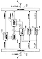
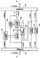
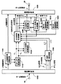
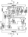
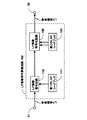
図1は、本発明に係る符号変換装置の第1の実施例の構成を示す図である。図1において、図26と同一または同等の要素には、同一の参照符号が付されている。図1を参照すると、第1の実施例の符号変換装置は、入力端子10と、符号分離回路1010と、LP係数符号変換回路1100と、LSP−LPC変換回路1110と、ACB符号生成回路1200と、音声復号回路1500と、FCB符号変換回路300と、ゲイン符号変換回路400と、符号多重回路1020と、出力端子20とを備えている。
【0093】
本発明の第1の実施例において、図1の入力端子10、出力端子20、符号分離回路1010、符号多重回路1020、FCB符号変換回路300およびゲイン符号変換回路400は、結線の一部が分岐する以外は、基本的に、図26に示した従来の符号変換装置の対応する要素と同じ構成からなる。なお、ACBゲインとFCBゲインは、まとめて符号化及び復号されるものとし、これを「ゲイン」と呼び、その符号を「ゲイン符号」と呼ぶことも、図26に示したものと同様である。
【0094】
本発明の第1の実施例に係る装置と、図26に示した装置との構成上の相違点は、図26のLP係数符号変換回路100が、LP係数符号変換回路1100で置き換えられており、LSP−LPC変換回路1110、ACB符号生成回路1200および音声復号回路1500が新たに付加されている点である。以下では、上述した同一または同等の要素の説明は省略し、本発明の第1の実施例について、主に、図26に示した構成との相違点について説明する。なお、後述する第4の実施例では、ACB符号生成回路1200を、ACB符号生成回路4200としたことが、第1の実施例との相違点であるため、この参照符号4200も併せて図1には示されており、図1は、第1の実施例の説明と第4の実施例の説明で共通に参照される。
【0095】
また、上記従来の構成と同様に、方式Aにおいて、LP係数の符号化は、T(A)fr msec周期(フレーム)毎に行われ、ACB、FCBおよびゲインなど励振信号の構成要素の符号化は、T(A)sfr=T(A)fr/N(A)sfr msec周期(サブフレーム)毎に行われるものとする。一方、方式Bにおいては、LP係数の符号化は、T(A)fr msec周期(フレーム)毎に行われ、励振信号の構成要素の符号化は、T( B )sfr=T( B )fr/N( B )sfr msec周期(サブフレーム)毎に行われるものとする。
【0096】
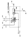
図2は、LP係数符号変換回路1100の構成を示す図である、図2を参照すると、LP係数符号変換回路1100は、LP係数復号回路110と、第1のLSPコードブック111と、LP係数符号化回路130と、第2のLSPコードブック131と、入力端子31、出力端子32、33、34を備えている。本実施例のLP係数符号変換回路1100の構成と、図28に示した従来のLP係数符号変換回路100の構成との相違点は、LP係数符号化回路130からの出力線および出力端子34と、出力端子33とを付加した点であり、各構成要素は、従来のLP係数符号変換回路100と同様である。以下では、上記相違点について説明する。
【0097】
LP係数符号化回路130は、出力端子32を介して出力する第2のLP係数符号に対応する第2のLSPを出力端子34を介して出力する。出力端子33からはLP係数復号回路110からの第1のLSPが出力される。以上で、LP係数符号変換回路1100の説明を終える。
【0098】
再び図1を参照すると、LSP−LPC変換回路1110は、LP係数符号変換回路1100から出力される第1のLSPと第2のLSPとを入力し、第1のLSPを第1のLP係数に変換し、第2のLSPを第2のLP係数に変換し、第1のLP係数a1,iをACB符号生成回路1200と音声復号回路1500とへ出力し、第2のLP係数a2,iをACB符号生成回路1200へ出力する。なお、LSPからLP係数への変換については、上述した従来の技術と同様に「文献3」の第3.2.6節の記載が参照される。
【0099】
音声復号回路1500は、符号分離回路1010から出力される第1のACB符号、第1のFCB符号、第1のゲイン符号を入力し、LSP−LPC変換回路1110から第1のLP係数a1,iを入力する。
【0100】
次に、方式Aにおける、ACB信号復号方法、FCB信号復号方法およびゲイン復号方法の各々を用いて、第1のACB符号、第1のFCB符号および第1のゲイン符号の各々から、ACB遅延、FCB信号およびゲインの各々を復号し、各々を第1のACB遅延、第1のFCB信号および第1のゲインとする。
【0101】
第1のACB遅延を用いてACB信号を生成し、これを第1のACB信号とする。
【0102】
そして、第1のACB信号、第1のFCB信号および第1のゲインと、第1のLP係数とから、音声を生成し、音声s(n)をACB符号生成回路1200へ出力する。
【0103】
また、第1のACB遅延T(A)lagをACB符号生成回路1200へ出力する。
【0104】
ACB符号生成回路1200は、LSP−LPC変換回路1110から第1のLP係数と第2のLP係数を入力し、音声復号回路1500から第1のACB符号に対応する第1のACB遅延T(A)lagと、復号音声s(n)とを入力し、これらから第2のACB遅延を求める。
【0105】
第2のACB遅延に対応する、方式Bにより復号可能な符号を、第2のACB符号として符号多重回路1020へ出力する。
【0106】
音声復号回路1500とACB符号生成回路1200の詳細な構成を以下に説明する。
【0107】
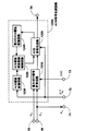
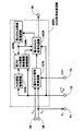
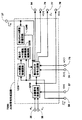
図3は、音声復号回路1500の構成を示す図である。図3を参照すると、音声復号回路1500は、ACB復号回路1510、FCB復号回路1520、ゲイン復号回路1530よりなる励振信号情報復号回路1600と、励振信号計算回路1540と、励振信号記憶回路1570と、合成フィルタ1580とを備えている。
【0108】
励振信号情報復号回路1600は、励振信号の情報に対応する符号から励振信号の情報を復号する。
【0109】
符号分離回路1010から出力される第1のACB符号、第1のFCB符号および第1のゲイン符号を各々入力端子51、52および53を介して入力し、第1のACB符号、第1のFCB符号および第1のゲイン符号の各々を、ACB復号回路1510、FCB復号回路1520、ゲイン復号回路1530にそれぞれ入力して、ACB遅延、FCB信号およびゲインの各々を、復号し、各々を第1のACB遅延、第1のFCB信号および第1のゲインとする。第1のゲインには、ACBゲインとFCBゲインが含まれており、各々を第1のACBゲインと第1のFCBゲインとする。
【0110】
また、励振信号情報復号回路1600のACB復号回路1510は、励振信号記憶回路1570から出力される過去の励振信号を入力する。ACB復号回路1510は、過去の励振信号と第1のACB遅延とを用いてACB信号を生成し、これを第1のACB信号とする。
【0111】
そして、励振信号情報復号回路1600は、第1のACB信号、第1のFCB信号、第1のACBゲインおよび第1のFCBゲインを、励振信号計算回路1540へ出力する。また、励振信号情報復号回路1600のACB復号回路1510は、第1のACB遅延を、ACB符号生成回路1200の後述されるACB遅延記憶回路1230とACB符号化回路1220とへ出力する。次に、励振信号情報復号回路1600の構成要素であるACB復号回路1510、FCB復号回路1520およびゲイン復号回路1530を詳細に説明する。
【0112】
ACB復号回路1510は、符号分離回路1010から出力される第1のACB符号を、入力端子51を介して入力し、励振信号記憶回路1570から出力される過去の励振信号を入力する。次に、ACB復号回路1510は、上述した従来の技術と同様にして、図16に示す方式AにおけるACB符号とACB遅延の対応関係を用いて、第1のACB符号に対応する第1のACB遅延T(A)frを得る。ACB復号回路1510は、励振信号において、現サブフレームの始点よりT(A)サンプル過去の点から、サブフレーム長に相当するL( A )sfrサンプルの信号を切り出して、第1のACB信号を生成する。ここで、T(A)がL( A )sfrよりも小さい場合には、T(A)サンプル分のベクトルを切り出し、このベクトルを繰り返し接続して、長さL( A )sfrサンプルの信号とする。
【0113】
そして、ACB復号回路1510は、第1のACB信号を励振信号計算回路1540へ出力し、第1のACB遅延を、出力端子62を介してACB遅延記憶回路1230とACB符号化回路1220とへ出力する。第1のACB信号を生成する方法の詳細については、「文献3」の第4.1.3節の記載が参照される。
【0114】
FCB復号回路1520は、符号分離回路1010から出力される第1のFCB符号を、入力端子52を介して入力する。FCB復号回路1520は、複数のFCB信号が格納されたテーブル(図示されない)を内蔵しており、第1のFCB符号に対応する第1のFCB信号をテーブルから読み出し、第1のFCB信号を励振信号計算回路1540へ出力する。なお、FCB信号の表現方法については、複数のパルスから成り、パルスの位置(パルス位置)と極性(パルス極性)により規定されるマルチパルス信号により、FCB信号を効率的に表現する方法を用いることもできる。この場合には、第1のFCB符号はパルス位置とパルス極性とに対応する。FCB信号をマルチパルスを用いて生成する方法の詳細については、「文献3」の第4.1.4節の記載が参照される。
【0115】
ゲイン復号回路1530は、符号分離回路1010から出力される第1のゲイン符号を、入力端子53を介して入力する。ゲイン復号回路1530は、複数のゲインが格納されたテーブル(図示されない)を内蔵しており、第1のゲイン符号に対応するゲインをテーブルから読み出す。
【0116】
そして、ゲイン復号回路1530は、読み出されたゲインのうち、ACBゲインに対応する第1のACBゲインと、FCBゲインに対応する第1のFCBゲインとを励振信号計算回路1540へ出力する。ここで、第1のACBゲインと第1のFCBゲインがまとめて符号化されている場合には、テーブルには第1のACBゲインと第1のFCBゲインとから成る2次元ベクトルが複数格納されている。また、第1のACBゲインと第1のFCBゲインが個別に符号化されている場合には、二つのテーブル(図示されない)が内蔵され、一方のテーブルに第1のACBゲインが複数格納されており、他方のテーブルに第1のFCBゲインが複数格納されている。
【0117】
励振信号計算回路1540は、ACB復号回路1510から出力される第1のACB信号を入力し、FCB復号回路1520から出力される第1のFCB信号を入力し、ゲイン復号回路1530から出力される第1のACBゲインと第1のFCBゲインとを入力する。励振信号計算回路1540は、第1のACB信号に第1のACBゲインを乗じて得た信号と、第1のFCB信号に第1のFCBゲインを乗じて得た信号と、を加算して第1の励振信号を得る。そして励振信号計算回路1540は、第1の励振信号を合成フィルタ1580と励振信号記憶回路1570とへ出力する。
【0118】
励振信号記憶回路1570は、励振信号計算回路1540から出力される第1の励振信号を入力し、これを記憶保持する。そして、過去に入力されて記憶保持されている過去の第1の励振信号を、ACB復号回路1510へ出力する。
【0119】
合成フィルタ1580は、励振信号計算回路1540から出力される第1の励振信号を入力し、LSP−LPC変換回路1110から出力される第1のLP係数を入力端子61を介して入力する。そして、合成フィルタ1580は、第1のLP係数をもつ線形予測フィルタを構成し、第1の励振信号により線形予測フィルタを駆動することにより音声信号を生成する。合成フィルタ1580は、音声信号を、ACB符号生成回路1200の重み付け信号計算回路1210へ出力端子63を介して出力する。
【0120】
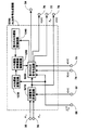
図4は、ACB符号生成回路1200の構成を示す図である。図4を参照すると、ACB符号生成回路1200は、重み付け信号計算回路1210と、ACB符号化回路1220と、ACB遅延記憶回路1230と、第2のACB遅延記憶回路1240と、ACB遅延探索範囲制御回路1250とを備えている。以下、各構成要素について説明する。
【0121】
ACB遅延記憶回路1230は、音声復号回路1500のACB復号回路1510(図3参照)から出力される第1のACB遅延を入力端子72を介して入力し、これを記憶保持する。
【0122】
ACB遅延記憶回路1230は、過去に入力されて記憶保持されている第1のACB遅延をACB遅延探索範囲制御回路1250へ出力する。
【0123】
重み付け信号計算回路1210は、合成フィルタ1580から出力される音声信号s(n)を入力端子73を介して入力し、LSP−LPC変換回路1110から出力される第1のLP係数と第2のLP係数を各々入力端子36と35を介して入力する。
【0124】
次に、重み付け信号計算回路1210は、第1のLP係数を用いて、聴感重み付けフィルタを構成する。そして、重み付け信号計算回路1210は、音声信号s(n)により聴感重み付けフィルタを駆動して得られる聴感重み付け音声信号を、ACB符号化回路1220へ出力する。ここで、聴感重み付けフィルタの伝達関数w(z)は次式(1)により表される。
【0125】

ただし、
A1(z)は、第1のLP係数a1,i(i=1,…P)をもつ線形予測フィルタの伝達関数であり、Pは線形予測次数(例えば、10)である。γ1とγ2は重み付けを制御する係数(例えば、0.94と0.6)である。聴感重み付け音声信号sw(n)は次式(3)により求められる。
【0128】
ここで、s(n)は音声信号である。なお、第1のLP係数の代りに、第2のLP係数を用いても良い。また、演算量低減のため、聴感重み付け音声信号の計算を省略して音声信号をそのまま用いることもできる。
【0130】
ACB符号化回路1220は、重み付け信号計算回路1210から出力される聴感重み付け音声信号を入力し、ACB復号回路1510から出力される第1のACB遅延を入力端子72を介して入力し、ACB遅延探索範囲制御回路1250から出力される探索範囲制御値を入力する。
【0131】
ACB符号化回路1220は、第1のACB遅延を中心とする、探索範囲制御値で規定される値の範囲内にある遅延について、聴感重み付け音声信号から自己相関を計算し、自己相関が最大となる遅延を選択し、この選択された遅延を第2のACB遅延とする。ここで、自己相関R(k)は次式(4)により表される。
【0132】
ただし、k、drange、T(A)lagは、各々遅延、探索範囲制御値、第1のACB遅延を表す。また、自己相関の代りに正規化自己相関を用いることもできる。正規化自己相関R'(k)は、次式(5)で表される。
【0134】
この場合、演算量低減のために、自己相関を用いて予備選択を行い、予備選択された複数候補の中から、正規化自己相関を用いて、本選択を行っても良い。
【0136】
次に、ACB符号化回路1220は、上述した従来の技術と同様にして、図16に示す方式BにおけるACB遅延とACB符号との対応関係を用いて、第2のACB遅延に対応する第2のACB符号を得る。そして、ACB符号化回路1220は、第2のACB符号を出力端子54を介して符号多重回路1020へ出力し、第2のACB遅延を第2のACB遅延記憶回路1240へ出力する。
【0137】
第2のACB遅延記憶回路1240は、ACB符号化回路1220から出力される第2のACB遅延を入力し、これを記憶保持する。そして、第2のACB遅延記憶回路1240は、過去に入力されて記憶保持されている第2のACB遅延をACB遅延探索範囲制御回路1250へ出力する。
【0138】
ACB遅延探索範囲制御回路1250は、ACB遅延記憶回路1230から出力される過去の第1のACB遅延を入力し、第2のACB遅延記憶回路1240から出力される過去の第2のACB遅延を入力する。
【0139】
次に、ACB遅延探索範囲制御回路1250は、過去の第1のACB遅延と、過去の第2のACB遅延とから、探索範囲制御値を計算する。ここで、第nフレーム第mサブフレームを簡単に時刻tで表すと、時刻tおける探索範囲制御値drange(t)は、次式(6)により計算される。
【0140】
ただし、T(A)lag(t)は時刻tにおける第1のACB遅延、T(B)lag(t)は時刻tにおける第2のACB遅延を表し、αは係数(例えば2)、Crangemaxは定数(例えば4)である。なお、これらの定数は、あらかじめ得た多数のd(t)の平均値から決めることもできる。
【0142】
また、d(t)を次式(7)により表すこともできる。
【0143】
ただし、Nrangeは定数(例えば、2)であり、w(k)は重み係数(例えば、w(1)=1.0, w(2)=0.8)である。最後に、上記計算により求めた探索範囲制御値をACB符号化回路1220へ出力する。以上により、ACB符号生成回路1200の説明を終える。
【0145】
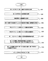
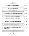
上記した第1の実施例において、第1の符号列を第2の符号列へ変換する符号変換の方法について、図1乃至図4と、図18を参照して説明しておく。図18は、本発明に係る方法の第1の実施例の動作を説明するための流れ図である。
【0146】
符号分離回路1010で分離された第1の符号列の符号(LP係数符号)から第1のLP係数を得る(ステップS101)。
【0147】
音声復号回路1500では、第1の符号列から、励振信号情報復号回路1600で励振信号の情報を得、励振信号計算回路1540で励振信号の情報から、励振信号を得る(ステップS102、S103)。
【0148】
音声復号回路1500では、第1のLP係数をもつ合成フィルタ1580を、得られた励振信号により駆動することによって、音声信号s(n)を生成する(ステップS104)。
【0149】
ACB符号生成回路1200において、音声復号回路1500で得られた励振信号の情報に含まれる第1のACB遅延T(A)lagを受け取りACB遅延記憶回路1230に記憶保持する(ステップS105)。
【0150】
ACB符号化回路1220で得られた第2の符号列におけるACB遅延の符号に対応する第2のACB遅延を、第2のACB遅延記憶回路1240に記憶保持する(ステップS106)。
【0151】
ACB符号生成回路1200において、記憶保持されている第1のACB遅延と、記憶保持されている第2のACB遅延とからACB遅延探索範囲制御回路1250は、探索範囲制御値を計算する(ステップS107)。
【0152】
ACB符号化回路1220は、第1のACB遅延と探索範囲制御値により規定される範囲内にある遅延から、音声信号s(n)を用いて、第2のACB遅延を選択し、第2のACB遅延に対応する符号を第2の符号列におけるACB遅延の符号として符号多重回路1020へ出力する(ステップS108)。
【0153】
ステップS105において、サブフレーム毎に第1のACB遅延を順次記憶し、所定のサブフレーム数分の前記第1のACB遅延を保持し、ステップS106において、サブフレーム毎に第2のACB遅延を順次記憶し、所定のサブフレーム数分の第2のACB遅延を保持する。
【0154】
ステップS107において、ACB符号化回路1220は、第1のACB遅延と第2のACB遅延との差分の絶対値を、保持されている全ての第1のACB遅延および第2のACB遅延について、同じサブフレームに対応するものどうしで計算し、絶対値に重み係数を乗じた値を、前記サブフレーム数分について加算した値を、探索範囲制御値とする。
【0155】
[実施例2]
図5は、本発明に係る符号変換装置の第2の実施例の構成を示す図である。図5を参照すると、第2の実施例は、ACB符号変換回路200から出力される第2のACB符号とACB符号生成回路1200から出力される第2のACB符号とを選択する構成である。この第2の実施例が、図1に示した前記第1の実施例と相違する点は、ACB符号変換回路200と切替器62がさらに設けられている点である。以下では、図1に示す要素と同一または同等の要素の構成の説明は省略し、相違点について主に説明する。
【0156】
ACB符号変換回路200は、図26に示した従来の技術のACB符号変換回路200と同等のものからなり、例えば第1サブフレームにおいて、第2のACB符号を求め、第2のACB符号を切替器62へ出力する。
【0157】
ACB符号生成回路1200は、前記第1の実施例におけるそれと同等である。ACB符号生成回路1200は、例えば第2サブフレームにおいて、第2のACB遅延を求め、第2のACB遅延に対応する、第2のACB符号を切替器62へ出力する。
【0158】
切替器62は、第1サブフレームにおいて、ACB符号変換回路200から出力される第2のACB符号を入力し、第2サブフレームにおいて、ACB符号生成回路1200から出力される第2のACB符号を入力し、第2のACB符号を符号多重回路1020へ出力する。
【0159】
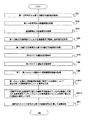
上記した第2の実施例において、第1の符号列を第2の符号列へ変換する符号変換の方法について、図5と、図19の流れ図を参照して説明しておく。図19は、本発明に係る方法の第2の実施例の動作を説明するための流れ図である。
【0160】
符号分離回路1010で分離された第1の符号列の符号(LP係数符号)から第1のLP係数を得る(ステップS201)。音声復号回路1500では、前記第1の実施例と同様、第1の符号列から励振信号の情報を得、励振信号の情報から、励振信号を得る(ステップS202、S203)。
【0161】
音声復号回路1500では、第1のLP係数をもつ合成フィルタ1580を、得られた励振信号により駆動することによって、音声信号s(n)を生成する(ステップS204)。
【0162】
ACB符号生成回路1200は、前記第1の実施例と同様、音声復号回路1500で得られた励振信号の情報に含まれる第1のACB遅延T(A)lagを受け取り記憶保持する(ステップS205)。
【0163】
ACB符号生成回路1200は、第2の符号列におけるACB遅延の符号に対応する第2のACB遅延を記憶保持する(ステップS206)。
【0164】
ACB符号生成回路1200は、記憶保持されている第1のACB遅延と記憶保持されている第2のACB遅延との差分の絶対値を、保持されている全ての第1のACB遅延および第2のACB遅延について、同じサブフレームに対応するものどうしで計算し、前記絶対値に重み係数を乗じた値を前記サブフレーム数分について加算した値を、探索範囲制御値とする(ステップS207)。
【0165】
ACB符号生成回路1200は、フレームにおける少なくとも一つのサブフレーム、例えば第2のサブフレームにおいて、第1のACB遅延と探索範囲制御値により規定される範囲内にある遅延から、音声信号s(n)を用いて、第2のACB遅延を選択し、第2のACB遅延に対応する符号を第2の符号列におけるACB遅延の符号として切替器62に出力する(ステップS208)。
【0166】
ACB符号変換回路200は、第1の符号列のACB符号を受け取り、フレームにおける少なくとも一つのサブフレーム、例えば第1のサブフレームにおいて、第1のACB遅延とそれに対応する第1の遅延符号との関係と、第2のACB遅延とそれに対応する第2の遅延符号との関係とを利用して、第1のACB遅延を第2のACB遅延に対応付けることによって、第1の遅延符号から第2の遅延符号への変換を行い、第2の遅延符号を第2の符号列におけるACB遅延の符号として切替器62に出力する(ステップS209)。
【0167】
切替器62は、例えば第1サブフレームでは、ACB符号変換回路200からの出力、例えば第2フレームでは、ACB符号生成回路1200からの出力に切替えて、符号多重回路1020に出力する(ステップS209)。
【0168】
[実施例3]
図6は、本発明に係る符号変換装置の第3の実施例の構成を示す図である。図6を参照すると、この第3の実施例は、ACB符号変換回路200から出力される第2のACB符号と、ACB符号生成回路3200から出力される第2のACB符号とを選択する。第3の実施例では、第2の実施例のACB符号生成回路1200を、ACB符号生成回路3200で置き換えたものである。以下では、主に、前述した相違点について説明する。
【0169】
ACB符号変換回路200は、付加された出力線を除いて上述した従来の技術におけるそれと同等である。第1サブフレームにおいて、第2のACB符号を求め、第2のACB符号を切替器62へ出力し、第2のACB符号に対応するACB遅延、すなわち第2のACB遅延をACB符号生成回路3200へ出力する。
【0170】
ACB符号生成回路3200は、第1サブフレームにおいて、ACB符号変換回路200から出力される第2のACB遅延を入力し、これを記憶保持する。第2サブフレームでは、LSP−LPC変換回路1110から出力される第1のLP係数と第2のLP係数とを入力し、音声復号回路1500から出力される第1のACB遅延と音声信号とを入力し、これらから第2のACB遅延を求める。そして、第2のACB遅延に対応する、方式Bにより復号可能な符号を、第2のACB符号として切替器62へ出力する。
【0171】
図7は、本発明の第3の実施例におけるACB符号生成回路3200の構成を示す図である。図7を参照すると、ACB符号生成回路3200は、重み付け信号計算回路1210と、第2のACB符号化回路3220と、ACB遅延記憶回路1230と、第2のACB遅延記憶回路1240と、第2のACB遅延探索範囲制御回路3250とを備えている。ACB符号生成回路3200の各構成要素について説明する。
【0172】
ACB符号生成回路3200の構成と、図4に示したACB符号生成回路1200の構成との相違点は、図4のACB遅延探索範囲制御回路1250を第2のACB遅延探索範囲制御回路3250とし、図4のACB符号化回路1220を第2のACB符号化回路3220としたことであり、他の各構成要素は結線の仕方を除いてACB符号生成回路1200と同様である。したがって、上記相違点についてのみ説明する。
【0173】
第2のACB遅延探索範囲制御回路3250は、ACB遅延記憶回路1230から出力される過去の第1のACB遅延を入力し、ACB復号回路1510から出力される(現在の)第1のACB遅延を入力する。次に、第2のACB遅延探索範囲制御回路3250は、過去の第1のACB遅延と、現在の第1のACB遅延とから、探索範囲制御値を計算する。ここで、第nフレーム第mサブフレームを簡単に時刻tで表すと、時刻tにおける探索範囲制御値drange(t)は次式(8)により計算される。
【0174】
ただし、T(A)lagは時刻tにおける第1のACB遅延を表し、αは係数(例えば、2)、Crangemaxは定数(例えば、4)である。これらの定数は、あらかじめ得た多数のd(t)の平均値から決めることもできる。
【0176】
また、d(t)を次式(9)により表すこともできる。
【0177】
ただし、Nrangeは定数(例えば、2)であり、w(k)は重み係数(例えば、w(1)=1.0, w(2)=0.8)である。
【0179】
第2のACB遅延探索範囲制御回路3250は、上記計算により求めた探索範囲制御値を第2のACB符号化回路3220へ出力する。
【0180】
第2のACB符号化回路3220は、第2サブフレームにおいて、第2のACB遅延記憶回路1240から出力される第2のACB遅延を入力し、重み付け信号計算回路1210から出力される聴感重み付け音声信号を入力し、第2のACB遅延探索範囲制御回路3250から出力される探索範囲制御値を入力する。
【0181】
第2のACB符号化回路3220は、第2のACB遅延を中心とする、探索範囲制御値で規定される値の範囲内にある遅延について、聴感重み付け音声信号から自己相関を計算し、自己相関が最大となる遅延を選択し、選択された遅延を、第2のACB遅延とする。なお、前記第1の実施例と同様に、自己相関の代りに、正規化自己相関を用いるようにしてもよい。自己相関および正規化自己相関の計算方法は、前記第1の実施例と同様である。
【0182】
次に、第2のACB符号化回路3220は、上述した従来の技術と同様にして、図27に示す方式BにおけるACB遅延とACB符号との対応関係を用いて、第2のACB遅延に対応する第2のACB符号を得る。そして、第2のACB符号を出力端子54を介して符号多重回路1020へ出力する。
【0183】
第2のACB遅延記憶回路1240は、結線の仕方を除いて上述した第1の実施例におけるそれと同等である。ACB符号変換回路200から第1サブフレームにおいて出力される第2のACB遅延を入力端子37を介して入力し、これを記憶保持する。そして、記憶保持されている第2のACB遅延を第2サブフレームにおいて第2のACB符号化回路3220へ出力する。
【0184】
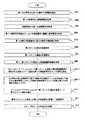
上記した第3の実施例において、第1の符号列を第2の符号列へ変換する符号変換の方法について、図6と、図20の流れ図を参照して説明しておく。図20は、本発明に係る方法の第3の実施例の動作を説明するための流れ図である。
【0185】
符号分離回路1010で分離された第1の符号列の符号(LP係数符号)から第1のLP係数を得る(ステップS301)。音声復号回路1500では、前記第1の実施例と同様、第1の符号列から励振信号の情報を得、励振信号の情報から、励振信号を得る(ステップS302、S303)、音声復号回路1500では、第1のLP係数をもつ合成フィルタ1580を、得られた励振信号により駆動することによって、音声信号s(n)を生成する(ステップS304)。励振信号の情報に含まれる第1のACB遅延を順次記憶し、あらかじめ定められたサブフレーム数分の第1のACB遅延を保持する(ステップS305)。
【0186】
サブフレーム毎に第2の符号列におけるACB遅延の符号に対応する第2のACB遅延を順次記憶し、あらかじめ定められたサブフレーム数分の第2のACB遅延を保持する(ステップS306)。
【0187】
ACB符号生成回路3200では、記憶保持されている過去の第1のACB遅延および現サブフレームの第1のACB遅延に対して連続するサブフレームの第1のACB遅延の差分を計算し、前記差分の絶対値を計算し、前記絶対値に重み係数を乗じた値を前記サブフレーム数分について加算した値を、探索範囲制御値とする(ステップS307)。
【0188】
ACB符号生成回路3200では、フレームにおける少なくとも一つのサブフレームにおいて、過去に求められて記憶保持されている第2のACB遅延と前記探索範囲制御値により規定される範囲内にある遅延から前記音声信号を用いて第2の適応コードブック遅延を選択し、前記第2の適応コードブック遅延に対応する符号を第2の符号列における適応コードブック遅延の符号として出力する(ステップS308)。
【0189】
ACB符号変換回路200では、前記フレームにおける少なくとも一つのサブフレーム(例えば第1フレーム)において、第1のACB遅延とそれに対応する第1の遅延符号との関係と、第2のACB遅延とそれに対応する第2の遅延符号との関係とを利用して、第1のACB遅延を第2のACB遅延に対応付けることによって前記第1の遅延符号から前記第2の遅延符号への変換を行い、前記第2の遅延符号を第2の符号列におけるACB遅延の符号として出力する(ステップS309)。ACB符号変換回路200から第2のACB遅延T( B )lagはACB符号生成回路3200に供給され、ステップS306で記憶保持される。
【0190】
切替器62は、ACB符号変換回路200から出力されるACB遅延の符号と、ACB符号生成回路3200から出力されるACB遅延の符号を切替えて符号多重回路1020に出力する(ステップS310)。
【0191】
[実施例4]
次に、図1を参照して、本発明に係る符号変換装置の第4の実施例を説明する。前述したように、この第4の実施例の説明では、第1の実施例で参照された図1が用いられる。第4の実施例と前記第1の実施例との構成上の相違点は、ACB符号生成回路1200をACB符号生成回路4200とした点である。
【0192】
図1のACB符号生成回路1200の構成を示した図4と、図8に示すACB符号生成回路4200の構成との相違点は、図4におけるACB遅延探索範囲制御回路1250を、図8の第3のACB遅延探索範囲制御回路4250とし、図4におけるACB符号化回路1220を、図8の第3のACB符号化回路4220で構成した点であり、他の各構成要素は結線の仕方を除いてACB符号生成回路1200と同様である。
【0193】
以下では、図8を参照して、第4の実施例における第3のACB遅延探索範囲制御回路4250と、第2のACB符号化回路4220について説明する。第3のACB遅延探索範囲制御回路4250は、ACB復号回路1510から出力される(現在の)第1のACB遅延を入力し、ACB遅延記憶回路1230から出力される過去の第1のACB遅延を入力し、第2のACB遅延記憶回路1240から出力される過去の第2のACB遅延を入力する。
【0194】
第3のACB遅延探索範囲制御回路4250は、第1サブフレームにおいては、過去の第1のACB遅延と、過去の第2のACB遅延とから、探索範囲制御値を計算する。ここで、第nフレーム第mサブフレームを簡単に時刻tで表すと、時刻tおける探索範囲制御値drange(t)は次式(10)により計算される。
【0195】
ただし、T(A)lagは時刻tにおける第1のACB遅延、T(B)lagは時刻tにおける第2のACB遅延を表し、α1は係数(例えば、2)、Crangemax1は定数(例えば、4)である。これらの定数は、あらかじめ得た多数のd(t)の平均値から決めることもできる。また、d(t)を次式(11)により表すこともできる。
【0197】
ただし、Nrange1は定数(例えば、2)であり、w1(k)は重み係数(例えば、w1(1)=1.0, w1(2)=0.8)である。
【0199】
第3のACB遅延探索範囲制御回路4250は、第2サブフレームにおいては、過去の第1のACB遅延と、現在の第1のACB遅延とから、探索範囲制御値を計算する。時刻tにおける探索範囲制御値drange(t)は次式(12)により計算される。
【0200】
ただし、α2は係数(例えば、2)、Crangemax2は定数(例えば、4)である。これらの定数は、同様に、あらかじめ得た多数のd(t)の平均値から決めることもできる。また、d(t)を次式(13)により表すこともできる。
【0202】
ただし、Nrange2は定数(例えば、2)であり、w2(k)は重み係数(例えば、w2(1)=1.0, w2(2)=0.8)である。
【0204】
第3のACB遅延探索範囲制御回路4250は、最後に、上記計算により求めた探索範囲制御値を第3のACB符号化回路4220へ出力する。
【0205】
第3のACB符号化回路4220は、重み付け信号計算回路1210から出力される聴感重み付け音声信号を入力し、ACB復号回路1510から出力される第1のACB遅延を入力端子72を介して入力し、第2のACB遅延記憶回路1240から出力される過去の第2のACB遅延を入力し、第3のACB遅延探索範囲制御回路4250から出力される探索範囲制御値を入力する。
【0206】
第3のACB符号化回路4220は、第1サブフレームにおいて、第1のACB遅延を中心とする、探索範囲制御値で規定される値の範囲内にある遅延について、聴感重み付け音声から自己相関を計算し、自己相関が最大となる遅延を選択し、この選択された遅延を第2のACB遅延とする。
【0207】
第3のACB符号化回路4220は、第2サブフレームにおいて、過去の第2のACB遅延を中心とする、探索範囲制御値で規定される値の範囲内にある遅延について、聴感重み付け音声から自己相関を計算し、自己相関が最大となる遅延を選択し、この選択された遅延を第2のACB遅延とする。ここで、上述した第1の実施例と同様に、自己相関の代りに正規化自己相関を用いてもよい。自己相関および正規化自己相関の計算方法は第1の実施例と同様である。
【0208】
次に、第3のACB符号化回路4220は、上述した従来の技術と同様にして、図27に示す方式BにおけるACB遅延とACB符号との対応関係を用いて、第2のACB遅延に対応する第2のACB符号を得る。そして、第2のACB符号を出力端子54を介して符号多重回路1020へ出力し、第2のACB遅延を第2のACB遅延記憶回路1240へ出力する。
【0209】
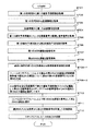
上記した第4の実施例において、第1の符号列を第2の符号列へ変換する符号変換の方法について、図1、図8と、図21の流れ図を参照して説明しておく。図21は、本発明に係る方法の第4の実施例の動作を説明するための流れ図である。
【0210】
符号分離回路1010で分離された第1の符号列の符号(LP係数符号)から第1のLP係数を得る(ステップS401)。音声復号回路1500では、第1の符号列から励振信号の情報を得、励振信号の情報から、励振信号を得る。(ステップS402、S403)、音声復号回路1500では、第1のLP係数をもつ合成フィルタを、得られた励振信号により駆動することによって、音声信号s(n)を生成する(ステップS404)。
【0211】
励振信号の情報に含まれる第1のACB遅延を順次記憶し、あらかじめ定められたサブフレーム数分の第1のACB遅延を保持する(ステップS405)。サブフレーム毎に第2の符号列におけるACB遅延の符号に対応する第2のACB遅延を順次記憶し、あらかじめ定められたサブフレーム数分の第2のACB遅延を保持する(ステップS406)。
【0212】
ACB符号生成回路4200では、フレームにおける少なくとも一つのサブフレームにおいて、記憶保持されている第1のACB遅延と記憶保持されている第2のACB遅延との差分の絶対値を、保持されている全ての第1のACB遅延および前記第2のACB遅延について同じサブフレームに対応するものどうしで計算し、前記絶対値に重み係数を乗じた値を前記サブフレーム数分について加算した値を、探索範囲制御値とし、他のサブフレームでは、記憶保持されている過去の第1のACB遅延および現サブフレームの前記第1のACB遅延に対して、連続するサブフレームの前記第1の適応コードブック遅延の差分を計算し、前記差分の絶対値を計算し、前記絶対値に重み係数を乗じた値を前記サブフレーム数分について加算した値を、探索範囲制御値とする(ステップS407)。
【0213】
ACB符号生成回路4200では、フレームにおける少なくとも一つのサブフレームでは、第1のACB遅延と上記探索範囲制御値により規定される範囲内にある遅延から音声信号s(n)を用いて第2のACB遅延を選択し、前記第2のACB遅延に対応する符号を第2の符号列におけるACB遅延の符号として出力する(ステップS408−1)。
【0214】
ACB符号生成回路4200は、他のサブフレームでは、過去に求められて記憶保持されている第2のACB遅延と前記探索範囲制御値により規定される範囲内にある遅延から音声信号s(n)を用いて第2のACB遅延を選択し、前記第2のACB遅延に対応する符号を第2の符号列におけるACB遅延の符号として出力する(ステップS408−2)。
【0215】
[実施例5]
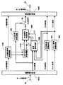
図9は、本発明に係る符号変換装置の第5の実施例の構成を示す図である。図9においては、符号変換後の符号に対応するLP係数と、音声信号(復号音声)とから、ACB符号、FCB符号およびゲイン符号を求める構成である。
【0216】
この第5の実施例と、図1に示した第1の実施例の構成との相違点は、図1のFCB符号変換回路300およびゲイン符号変換回路400が削除されており、ACB符号生成回路1200をACB符号生成回路5200で構成し、インパルス応答計算回路5120、FCB符号生成回路5300、ゲイン符号生成回路5400、第2の励振信号計算回路5610および第2の励振信号記憶回路5620が付加されている点である。以下では、図1に示す要素と同一または同等の要素の説明は省略し、主に、前述した相違点について説明する。なお、後述する第8の実施例において、ACB符号生成回路5200を、ACB符号生成回路8200とした点が、本実施例との相違点であるため、この参照符号8200も併せて示し、図9はこれら2つの実施例の説明で共用される。
【0217】
ACB符号生成回路5200は、LSP−LPC変換回路1110から第1のLP係数と第2のLP係数とを入力し、音声復号回路1500から第1のACB符号に対応する第1のACB遅延と復号音声とを入力し、インパルス応答計算回路5120からインパルス応答信号を入力し、第2の励振信号記憶回路5620に記憶保持される過去の第2の励振信号を入力する。
【0218】
ACB符号生成回路5200は、復号音声と第1のLP係数および第2のLP係数とから第1の目標信号を計算する。
【0219】
次に、ACB符号生成回路5200は、過去の第2の励振信号とインパルス応答信号と第1の目標信号とから、第2のACB遅延と第2のACB信号および最適ACBゲインを求める。
【0220】
そして、ACB符号生成回路5200は、第1の目標信号をFCB符号生成回路5300とゲイン符号生成回路5400とへ出力し、最適ACBゲインをFCB符号生成回路5300へ出力し、第2のACB信号をFCB符号生成回路5300とゲイン符号生成回路5400と第2の励振信号計算回路5610とへ出力し、第2のACB遅延に対応する、方式Bにより復号可能な符号を、第2のACB符号として符号多重回路1020へ出力する。
【0221】
インパルス応答計算回路5120は、LSP−LPC変換回路1110から出力される第1のLP係数と第2のLP係数を入力し、第1のLP係数と第2のLP係数とを用いて聴感重み付け合成フィルタを構成する。そして、インパルス応答計算回路5120は、聴感重み付け合成フィルタのインパルス応答信号をACB符号生成回路5200とFCB符号生成回路5300とゲイン符号生成回路5400とへ出力する。ここで、聴感重み付け合成フィルタW(z)の伝達関数は次式(14)により表される。
【0222】
ただし、
は、第2のLP係数α2,i,i=1,…,Pをもつ線形予測フィルタの伝達関数である。
【0225】
FCB符号生成回路5300は、ACB符号生成回路5200から出力される第1の目標信号と第2のACB信号と最適ACBゲインとを入力し、インパルス応答計算回路5120から出力されるインパルス応答信号を入力する。
【0226】
FCB符号生成回路5300は、第1の目標信号と第2のACB信号と最適ACBゲインとインパルス応答信号とから第2の目標信号を計算する。
【0227】
次に、FCB符号生成回路5300は、第2の目標信号と、FCB符号生成回路5300が内蔵するテーブルに格納されたFCB信号と、インパルス応答信号とから、第2の目標信号との距離が最小となるFCB信号を求める。
【0228】
そして、FCB符号生成回路5300は、FCB信号に対応する、方式Bにより復号可能な符号を、第2のFCB符号として符号多重回路1020へ出力し、FCB信号を、第2のFCB信号としてゲイン符号生成回路5400と第2の励振信号計算5610とへ出力する。
【0229】
ゲイン符号生成回路5400は、ACB符号生成回路5200から出力される第1の目標信号と第2のACB信号とを入力し、FCB符号生成回路5300から出力される第2のFCB信号を入力し、インパルス応答計算回路5120から出力されるインパルス応答信号を入力する。
【0230】
ゲイン符号生成回路5400は、第1の目標信号と第2のACB信号と第2のFCB信号とインパルス応答信号と、ゲイン符号生成回路5400が内蔵するテーブルに格納されたACBゲインとFCBゲインとから計算される、第1の目標信号と再構成音声との重み付け自乗誤差を最小にするACBゲインとFCBゲインとを求める。そして、ゲイン符号生成回路5400は、ACBゲインおよびFCBゲインに対応する、方式Bにより復号可能な符号を、第2のゲイン符号として符号多重回路1020へ出力し、ACBゲインおよびFCBゲインを、各々第2のACBゲインおよび第2のFCBゲインとして第2の励振信号計算回路5610へ出力する。
【0231】
第2の励振信号計算回路5610は、ACB符号生成回路5200から出力される第2のACB信号を入力し、FCB符号生成回路5300から出力される第2のFCB信号を入力し、ゲイン符号生成回路5400から出力される第2のACBゲインと第2のFCBゲインとを入力する。
【0232】
第2の励振信号計算回路5610は、第2のACB信号に第2のACBゲインを乗じて得た信号と、第2のFCB信号に第2のFCBゲインを乗じて得た信号と、を加算して第2の励振信号を得る。そして第2の励振信号を第2の励振信号記憶回路5620へ出力する。
【0233】
第2の励振信号記憶回路5620は、第2の励振信号計算回路5610から出力される第2の励振信号を入力し、これを記憶保持する。そして、過去に入力されて記憶保持されている第2の励振信号をACB符号生成回路5200へ出力する。
【0234】
ACB符号生成回路5200とFCB符号生成回路5300とゲイン符号化回路5400の詳細な構成を以下に説明する。
【0235】
図10は、ACB符号生成回路5200の構成を示す図である。図10を参照して、ACB符号生成回路5200の各構成要素について説明する。
【0236】
図10を参照すると、ACB符号生成回路5200は、図4に示したACB符号生成回路1200の構成と比較して、図4の重み付け信号計算回路1210とACB符号化回路1220に代りに、目標信号計算回路5210と第4のACB符号化回路5220とを備えており、他の各構成要素はACB符号生成回路1200におけるそれらと同様であるため、以下では、ACB符号生成回路5200について、ACB符号生成回路1200との相違点について説明する。
【0237】
目標信号計算回路5210は、合成フィルタ1580から出力される復号音声を入力端子57を介して入力し、LSP−LPC変換回路1110から出力される第1のLP係数と第2のLP係数とを、各々入力端子36と入力端子35とを介して入力する。
【0238】
まず、目標信号計算回路5210は、第1のLP係数を用いて、聴感重み付けフィルタを構成する。そして、復号音声により聴感重み付けフィルタを駆動して聴感重み付け音声信号を生成する。ここで、聴感重み付けフィルタの伝達関数は、重み付け信号計算回路1210におけるそれと同様に、W(z)で表される。
【0239】
次に、目標信号計算回路5210は、第1のLP係数と第2のLP係数とを用いて、聴感重み付け合成フィルタを構成する。そして、目標信号計算回路5210は、聴感重み付け合成フィルタの零入力応答を聴感重み付け音声信号から減算して得られる第1の目標信号を、第4のACB符号化回路5220へ出力するとともに、第2の目標信号計算回路5310とゲイン符号化回路5410とへ出力端子78を介して出力する。ここで、聴感重み付け合成フィルタの伝達関数は次式(16)により表される。
【0240】
第4のACB符号化回路5220は、目標信号計算回路5210から出力される第1の目標信号を入力し、ACB復号回路1510から出力される第1のACB遅延を入力端子58を介して入力し、ACB遅延探索範囲制御回路1250から出力される探索範囲制御値を入力し、インパルス応答計算回路5120から出力されるインパルス応答信号を入力端子74を介して入力し、第2の励振信号記憶回路5620から出力される過去の第2の励振信号を入力端子75を介して入力する。
【0242】
第4のACB符号化回路5220は、過去の第2の励振信号から遅延kで切り出された信号とインパルス応答信号との畳み込みにより、フィルタ処理された遅延kの過去の励振信号yk(n)、n=0,…,L(B)sfr−1を計算する。
【0243】
次に、第4のACB符号化回路5220は、第1のACB遅延を中心とする、探索範囲制御値で規定される値の範囲内にある遅延kについて、yk(n)と第1の目標信号x(n)とから正規化相互相関を計算し、正規化相互相関が最大となる遅延を選択する。これは、x(n)とyk(n)との自乗誤差が最小となる遅延を選択することに対応する。選択された遅延を第2のACB遅延とし、過去の第2の励振信号から第2のACB遅延で切り出された信号を第2のACB信号v(n)とする。ここで、正規化相互相関Rxy(k)は次式(17)により表される。
【0244】
また、第4のACB符号化回路5220は、第2のACB信号から最適ACBゲインgpを次式(18)により計算する。
【0246】
最後に、第4のACB符号化回路5220は、上述した従来の技術と同様にして、図27に示す方式BにおけるACB遅延とACB符号との対応関係を用いて、第2のACB遅延に対応する、方式Bにより復号可能な符号を求め、これを第2のACB符号として出力端子54を介して符号多重回路1020へ出力する。また、第4のACB符号化回路5220は、第2のACB遅延を第2のACB遅延記憶回路1240へ出力し、第2のACB信号を第2の目標信号計算回路5310(図11参照)とゲイン符号化回路5410(図12参照)と第2の励振信号計算回路5610とへ出力端子76を介して出力し、最適ACBゲインを第2の目標信号計算回路5310へ出力端子77を介して出力する。なお、第2のACB遅延を求める方法、第2のACB信号を計算する方法および最適ACBゲインを計算する方法の詳細については、「文献3」の第3.7節の記載が参照される。以上によりACB符号生成回路5200の説明を終える。
【0248】
図11は、FCB符号生成回路5300の構成を示す図である。図11を参照して、FCB符号生成回路5300の各構成要素について説明する。
【0249】
第2の目標信号計算回路5310は、目標信号計算回路5210から出力される第1の目標信号を入力端子81を介して入力し、インパルス応答計算回路5120から出力されるインパルス応答信号を入力端子84を介して入力し、第4のACB符号化回路5220から出力される第2のACB信号と最適ACBゲインとを各々入力端子83と82を介して入力する。
【0250】
第2の目標信号計算回路5310は、第2のACB信号とインパルス応答信号との畳み込みにより、フィルタ処理された第2のACB信号y(n)、n=0,…,L(B)sfr−1を計算し、y(n)に最適ACBゲインを乗じて得られる信号を第1の目標信号から減算して第2の目標信号x'(n)を得る。
【0251】
そして、第2の目標信号計算回路5310は、第2の目標信号をFCB符号化回路5320へ出力する。
【0252】
FCB符号化回路5320は、第2の目標信号計算回路5310から出力される第2の目標信号を入力し、インパルス応答計算回路5120から出力されるインパルス応答信号を入力端子84を介して入力する。FCB符号化回路5320は、複数のFCB信号が格納されたテーブルを内蔵しており、FCB信号をテーブルから順次読み出し、FCB信号とインパルス応答信号との畳み込みにより、フィルタ処理されたFCB信号z(n)、n=0,…,L(B)sfr−1を順次計算する。
【0253】
次に、FCB符号化回路5320は、z(n)と第2の目標信号x'(n)とから正規化相互相関を順次計算し、正規化相互相関が最大となるFCB信号を選択する。これは、x'(n)とz(n)との自乗誤差が最小となるFCB信号を選択することに対応する。ここで、正規化相互相関Rxy(k)は次式(19)により表される。
【0254】
選択されたFCB信号を第2のFCB信号c(n)とする。そして、FCB符号化回路5320は、第2のFCB信号に対応する、方式Bにより復号可能な符号を、第2のFCB符号として符号多重回路1020へ出力端子55を介して出力し、第2のFCB信号をゲイン符号化回路5410と第2の励振信号計算回路5610とへ出力端子85を介して出力する。
【0256】
なお、上述した第1の実施例における第1のFCB信号と同様に、FCB信号の表現方法については、複数のパルスから成り、パルス位置とパルス極性により規定されるマルチパルス信号により、FCB信号を効率的に表現する方法を用いることもでき、この場合には、第2のFCB符号はパルス位置とパルス極性とに対応する。ここで、FCB信号をマルチパルスで表現した場合の符号化方法の詳細については、「文献3」の第3.8節の記載が参照できる。以上によりFCB符号生成回路5300の説明を終える。
【0257】
図12は、ゲイン符号生成回路5400の構成を示す図である。図12を参照して、ゲイン符号生成回路5400の構成要素である、ゲイン符号化回路5410について説明する。
【0258】
ゲイン符号化回路5410は、目標信号計算回路5210から出力される第1の目標信号を入力端子93を介して入力し、第4のACB符号化回路5220から出力される第2のACB信号を入力端子92を介して入力し、FCB符号化回路5320から出力される第2のFCB信号を入力端子91を介して入力し、インパルス応答計算回路5120から出力されるインパルス応答信号を入力端子94を介して入力する。
【0259】
ゲイン符号化回路5410は、複数のACBゲインと複数のFCBゲインとが格納されたテーブル(不図示)を内蔵しており、ACBゲインとFCBゲインをテーブルから順次読み出し、第2のACB信号と第2のFCB信号とインパルス応答信号とACBゲインとFCBゲインとから重み付け再構成音声を順次計算し、重み付け再構成音声と、第1の目標信号との重み付け自乗誤差を順次計算し、重み付け自乗誤差を最小にするACBゲインとFCBゲインを選択する。ここで、重み付け自乗誤差Eは次式(20)により表される。
【0260】
ただし、^gpと^gcは、各々ACBゲインとFCBゲインである。また、y(n)はフィルタ処理された第2のACB信号であり、第2のACB信号とインパルス応答信号との畳み込みにより得られ、z(n)はフィルタ処理された第2のFCB信号であり、第2のFCB信号とインパルス応答信号との畳み込みにより得られる。なお、重み付け再構成音声は次式(21)により表される。
【0262】
![]()
最後に、ゲイン符号化回路5410は、ACBゲインおよびFCBゲインに対応する、方式Bにより復号可能な符号を、第2のゲイン符号として出力端子56を介して符号多重回路1020へ出力し、ACBゲインおよびFCBゲインを、各々第2のACBゲインおよび第2のFCBゲインとして出力端子95と96を介して第2の励振信号計算回路5610へ出力する。以上によりゲイン符号生成回路5400の説明を終える。
【0264】
上記した第5の実施例において、第1の符号列を第2の符号列へ変換する符号変換の方法について、図9、図10と、図22の流れ図を参照して説明しておく。図22は、本発明に係る方法の第5の実施例の動作を説明するための流れ図である。
【0265】
符号分離回路1010で分離された第1の符号列の符号(LP係数符号)から第1のLP係数を得る(ステップS501)。音声復号回路1500では、第1の符号列から励振信号の情報を得、励振信号の情報から、励振信号を得る(ステップS502、S503)。音声復号回路1500では、第1のLP係数をもつ合成フィルタを、得られた励振信号により駆動することによって、音声信号s(n)を生成する(ステップS504)。
【0266】
LP係数符号変換回路1100で第1のLP係数から第2のLP係数を得る(ステップS505)。
【0267】
ACB符号生成回路5200では、得られた励振信号の情報に含まれる第1のACB遅延を記憶保持する(ステップS506)。
【0268】
ACB符号生成回路5200では、第2の符号列におけるACB遅延の符号に対応する第2のACB遅延を記憶保持する(ステップS507)。
【0269】
ACB符号生成回路5200では、記憶保持されている第1のACB遅延と、記憶保持されている第2のACB遅延とから探索範囲制御値を計算し(ステップS508)、第1のACB遅延と前記探索範囲制御値により規定される範囲内にある遅延について、過去に計算されて記憶保持されている第2の励振信号からACB信号を順次生成する(ステップS509−1)。
【0270】
ACB符号生成回路5200では、ACB信号により第2のLP係数をもつ合成フィルタを駆動することで、順次生成される第1の再構成音声信号と前記音声信号とを用いてACB信号と第2のACB遅延を選択し、第2のACB遅延に対応する符号を第2の符号列におけるACB遅延の符号として出力する(ステップS509−2)。
【0271】
第2の励振信号計算回路5610では、選択されたACB信号から第2の励振信号を得、第2の励振信号を記憶保持する(ステップS510)。
【0272】
[実施例6]
図13は、本発明に係る符号変換装置の第6の実施例の構成を示す図である。図13においては、ACB符号変換回路200から出力される第2のACB符号と、ACB符号生成回路5200から出力される第2のACB符号と、を選択する構成である。図13を参照すると、第6の実施例が、図9に示した構成と相違する点は、ACB符号変換回路200および第2の切替器62が付加されている点である。以下では、図9に示す要素と同一または同等の要素の説明は省略する。
【0273】
図13において、ACB符号変換回路200は、図26に示した従来の技術のACB符号変換回路200と同等のものからなり、例えば第1サブフレームにおいて、第2のACB符号を求め、第2のACB符号を切替器62へ出力する。
【0274】
ACB符号生成回路5200は、例えば第2サブフレームにおいて、第2のACB遅延を求め、第2のACB遅延に対応する、第2のACB符号を切替器62へ出力する。
【0275】
切替器62は、第1サブフレームにおいて、ACB符号変換回路200から出力される第2のACB符号を入力し、第2サブフレームにおいて、ACB符号生成回路5200から出力される第2のACB符号を入力し、第2のACB符号を符号多重回路1020へ出力する。
【0276】
上記した第6の実施例において、第1の符号列を第2の符号列へ変換する符号変換の方法について、図10、図13と、図23の流れ図を参照して説明しておく。図23は、本発明に係る方法の第6の実施例の動作を説明するための流れ図である。
【0277】
符号分離回路1010で分離された第1の符号列の符号(LP係数符号)から第1のLP係数を得る(ステップS601)。音声復号回路1500では、第1の符号列から励振信号の情報を得、励振信号の情報から、励振信号を得る(ステップS602、S603)。音声復号回路1500では、第1のLP係数をもつ合成フィルタを、得られた励振信号により駆動することによって、音声信号s(n)を生成する(ステップS604)。LP係数符号変換回路1100で第1のLP係数から第2のLP係数を得る(ステップS605)。
【0278】
サブフレーム毎に、前記励振信号の情報に含まれる第1のACB遅延を順次記憶し、あらかじめ定められたサブフレーム数分の前記第1のACB遅延を保持する(ステップS606)。
【0279】
前記サブフレーム毎に、前記第2の符号列における適応コードブック遅延の符号に対応する第2の適応コードブック遅延を順次記憶し、あらかじめ定められたサブフレーム数分の前記第2のACB遅延を保持する(ステップS607)。
【0280】
ACB符号生成回路5200では、記憶保持されている前記第1のACB遅延と、記憶保持されている前記第2のACB遅延との差分の絶対値を、保持されている全ての前記第1のACB遅延および第2のACB遅延について同じサブフレームに対応するものどうしで計算し、前記絶対値に重み係数を乗じた値を前記サブフレーム数分について加算した値を、前記探索範囲制御値とする(ステップS608)。
【0281】
フレームにおける少なくとも一つのサブフレームにおいて、前記第1のACB遅延と前記探索範囲制御値により規定される範囲内にある遅延について、過去に計算されて記憶保持されている第2の励振信号からACB信号を順次生成し(ステップS609−1)、生成されたACB信号により前記第2のLP係数をもつ合成フィルタを駆動することで順次生成される第1の再構成音声信号と前記音声信号とを用いてACB信号と第2のACB遅延を選択し、前記第2のACB遅延に対応する符号を第2の符号列におけるACB遅延の符号として出力する(ステップS609−2)。
【0282】
ACB符号変換回路200では、フレームにおける少なくとも一つのサブフレームにおいて、第1のACB遅延を基準として第2のACB遅延を選択する。すなわち、第1のACB遅延とそれに対応する第1の遅延符号との関係と、第2のACB遅延とそれに対応する第2の遅延符号との関係とを利用して、前記第1のACB遅延を前記第2のACB遅延に対応付けることによって前記第1の遅延符号から前記第2の遅延符号への変換を行い、第2の遅延符号を第2の符号列におけるACB遅延の符号として出力する(ステップS610)。
【0283】
前記選択された適応コードブック信号から第2の励振信号を得、前記第2の励振信号を記憶保持する(ステップS611)。
【0284】
ACB符号変換回路200とACB符号生成回路5200からの出力を切替器62で切替えて符号多重回路1020に出力する(ステップS611)。
【0285】
[実施例7]
図14は、本発明に係る符号変換装置の第7の実施例の構成を示す図である。図14においては、ACB符号変換回路200から出力される第2のACB符号と、ACB符号生成回路7200から出力される第2のACB符号と、を選択する構成である。ここで、ACB符号変換回路200は、上述した第3の実施例におけるそれと同等であり、前記第6の実施例との構成上の相違点は、ACB符号生成回路5200を、ACB符号生成回路7200で構成した点である。以下にACB符号生成回路7200の構成を説明する。
【0286】
ACB符号生成回路7200は、ACB符号変換回路200から出力される第2のACB遅延を入力し、LSP−LPC変換回路1110から第1のLP係数と第2のLP係数とを入力し、音声復号回路1500から第1のACB遅延と復号音声とを入力し、インパルス応答計算回路5120からインパルス応答信号を入力し、第2の励振信号記憶回路5620に記憶保持されている過去の第2の励振信号を入力する。
【0287】
ACB符号生成回路7200は、復号音声と第1のLP係数および第2のLP係数とから第1の目標信号を計算する。
【0288】
次に、ACB符号生成回路7200は、第1サブフレームにおいて、第2のACB遅延と過去の第2の励振信号とインパルス応答信号とから、第2のACB信号および最適ACBゲインを求め、第2のACB遅延を記憶保持する。
【0289】
ACB符号生成回路7200は、第2サブフレームでは、記憶保持されている第2のACB遅延と過去の第2の励振信号とインパルス応答信号と第1の目標信号とから、第2のACB遅延と第2のACB信号および最適ACBゲインを求める。
【0290】
そして、ACB符号生成回路7200は、第1の目標信号をFCB符号生成回路5300とゲイン符号生成回路5400とへ出力し、最適ACBゲインをFCB符号生成回路5300へ出力し、第2のACB信号をFCB符号生成回路5300とゲイン符号生成回路5400と第2の励振信号計算回路5610とへ出力する。また、ACB符号生成回路7200は、第2サブフレームにおいて、第2のACB遅延に対応する、方式Bにより復号可能な符号を、第2のACB符号として切替器62へ出力する。
【0291】
図15は、ACB符号生成回路7200の構成を示す図である。図15を参照して、ACB符号生成回路7200の各構成要素について説明する。
【0292】
ACB符号生成回路7200の構成と、図10に示すACB符号生成回路5200の構成との相違点は、図10のACB遅延探索範囲制御回路1250を第2のACB遅延探索範囲制御回路3250とし、第4のACB符号化回路5220を第5のACB符号化回路7220で構成した点であり、他の各構成要素は結線の仕方を除いてACB符号生成回路5200におけるそれらと同様であり、また、第2のACB遅延探索範囲制御回路3250は、図7に示す第3の実施例におけるそれと同等である。以下、第5のACB符号化回路7220について説明する。
【0293】
第5のACB符号化回路7220は、目標信号計算回路5210から出力される第1の目標信号を入力し、第2のACB遅延探索範囲制御回路3250から出力される探索範囲制御値を入力し、インパルス応答計算回路5120から出力されるインパルス応答信号を入力端子74を介して入力し、第2の励振信号記憶回路5620から出力される過去の第2の励振信号を入力端子75を介して入力する。さらに、第5のACB符号化回路7220は、第1のサブフレームでは、ACB符号変換回路200から出力される第2のACB遅延を入力端子37を介して入力し、第2サブフレームでは、第2のACB遅延記憶回路1240から出力される過去の第2のACB遅延を入力する。
【0294】
第5のACB符号化回路7220は、第1のサブフレームにおいて、過去の第2の励振信号から第2のACB遅延で切り出された信号を第2のACB信号v(n)とする。また、第5のACB符号化回路7220は、第2のACB信号から最適ACBゲインgpを計算する。
【0295】
第5のACB符号化回路7220は、第2のサブフレームでは、まず、過去の第2の励振信号から遅延kで切り出された信号とインパルス応答信号との畳み込みにより、フィルタ処理された遅延kの過去の励振信号yk(n),n=0,…,L( B )sfr-1を計算する。
【0296】
次に、第5のACB符号化回路7220は、過去の第2のACB遅延を中心とする、探索範囲制御値で規定される値の範囲内にある遅延kについて、yk(n)と第1の目標信号x(n)とから正規化相互相関を計算し、正規化相互相関が最大となる遅延を選択する。これは、x(n)とyk(n)との自乗誤差が最小となる遅延を選択することに対応する。選択された遅延を第2のACB遅延とし、過去の第2の励振信号から第2のACB遅延で切り出された信号を第2のACB信号v(n)とする。
【0297】
また、第5のACB符号化回路7220は、第2のACB信号から最適ACBゲインgpを計算する。
【0298】
最後に、第5のACB符号化回路7220は、上述した従来の技術と同様にして、図27に示す方式BにおけるACB遅延とACB符号との対応関係を用いて、第2のACB遅延に対応する、方式Bにより復号可能な符号を求め、これを第2のACB符号として出力端子54を介して切替器62へ出力する。
【0299】
また、第5のACB符号化回路7220は、第2のACB信号を第2の目標信号計算回路5310とゲイン符号化回路5410と第2の励振信号計算回路5610とへ出力端子76を介して出力し、最適ACBゲインを第2の目標信号計算回路5310へ出力端子77を介して出力する。以上により図15の説明を終える。これで第7の実施例の説明を終える。
【0300】
上記した第7の実施例において、第1の符号列を第2の符号列へ変換する符号変換の方法について、図14、図15と、図24の流れ図を参照して説明しておく。図24は、本発明に係る方法の第7の実施例の動作を説明するための流れ図である。
【0301】
第1の符号列から第1のLP係数を得る(ステップS701)。第1の符号列から励振信号の情報を得、励振信号の情報から第1の励振信号を得、第1のLP係数をもつフィルタを第1の励振信号により駆動することによって音声信号を生成する(ステップS702〜S704)。LP係数符号変換回路1100で、第1のLP係数から第2のLP係数を得る(ステップS705)。
【0302】
ACB符号生成回路7200では、サブフレーム毎に、前記励振信号の情報に含まれる第1のACB遅延を順次記憶し、あらかじめ定められたサブフレーム数分の前記第1のACB遅延を保持する(ステップS706)。サブフレーム毎に、前記第2の符号列におけるACB遅延の符号に対応する第2のACB遅延を順次記憶し、あらかじめ定められたサブフレーム数分の前記第2のACB遅延を保持する(ステップS707)。
【0303】
ACB符号生成回路7200では、記憶保持されている過去の第1のACB遅延および現サブフレームの前記第1のACB遅延に対して、連続するサブフレームの前記第1のACB遅延の差分を計算し、前記差分の絶対値を計算し、前記絶対値に重み係数を乗じた値を前記サブフレーム数分について加算した値を、探索範囲制御値とする(ステップS708)。
【0304】
前記フレームにおける少なくとも一つのサブフレームにおいて、過去に求められて記憶保持されている前記第2のACB遅延と探索範囲制御値により規定される範囲内にある遅延について、過去に計算されて記憶保持されている第2の励振信号からACB信号を順次生成する(ステップS709−1)。
【0305】
ACB符号生成回路7200では、ACB信号により第2のLP係数をもつ合成フィルタを駆動することで順次生成される第1の再構成音声信号と前記音声信号とを用いて、ACB信号と第2のACB遅延を選択し、第2のACB遅延に対応する符号を第2の符号列におけるACB遅延の符号として出力する(ステップS709−2)。
【0306】
ACB符号変換回路200は、前記フレームにおける少なくとも一つのサブフレームにおいて、前記第1のACB遅延とそれに対応する第1の遅延符号との関係と、前記第2のACB遅延とそれに対応する第2の遅延符号との関係とを利用して、前記第1のACB遅延を前記第2のACB遅延に対応付けることによって前記第1の遅延符号から前記第2の遅延符号への変換を行い、前記第2の遅延符号を第2の符号列におけるACB遅延の符号として出力する(ステップS710)。ACB符号変換回路200から出力される第2のACB遅延T(B)lagはACB符号生成回路7200に供給される。
【0307】
前記選択されたACB信号から第2の励振信号計算回路5620で第2の励振信号を得、第2の励振信号を記憶保持する(ステップS711)。
【0308】
ACB符号変換回路200からの出力とACB符号生成回路7200からの出力を切替器62で切替えて符号多重回路1020に供給する。
【0309】
[実施例8]
図9は、本発明に係る符号変換装置の第8の実施例の構成を示す図である。前述したように、この実施例は、第5の実施例と図9を共用している。この第8の実施例と、第5の実施例との構成上の相違点は、ACB符号生成回路5200をACB符号生成回路8200とした点である。以下にACB符号生成回路8200の構成を説明する。
【0310】
図16は、ACB符号生成回路8200の構成を示す図である。図16を参照して、ACB符号生成回路8200の各構成要素について説明する。
【0311】
ACB符号生成回路8200の構成と、図10に示したACB符号生成回路5200の構成との相違点は、ACB遅延探索範囲制御回路1250を第3のACB遅延探索範囲制御回路4250とし、第4のACB符号化回路5220を第6のACB符号化回路8220で構成した点であり、他の各構成要素は結線の仕方を除いてACB符号生成回路5200におけるそれらと同様であり、また、第3のACB遅延探索範囲制御回路4250は、図8に示す第4の実施例におけるそれと同等である。以下では、第6のACB符号化回路8220を説明する。
【0312】
第6のACB符号化回路8220は、目標信号計算回路5210から出力される第1の目標信号を入力し、ACB復号回路1510から出力される第1のACB遅延を入力端子58を介して入力し、第2のACB遅延記憶回路1240から出力される過去の第2のACB遅延を入力し、第3のACB遅延探索範囲制御回路4250から出力される探索範囲制御値を入力し、インパルス応答計算回路5120から出力されるインパルス応答信号を入力端子74を介して入力し、第2の励振信号記憶回路5620から出力される過去の第2の励振信号を入力端子75を介して入力する。
【0313】
次に、第6のACB符号化回路8220は、過去の第2の励振信号から遅延kで切り出された信号とインパルス応答信号との畳み込みにより、フィルタ処理された遅延kの過去の励振信号yk(n),n=0,…,L( B )sfr-1を計算する。
【0314】
第6のACB符号化回路8220は、第1サブフレームにおいて、第1のACB遅延を中心とする、探索範囲制御値で規定される値の範囲内にある遅延kについて、yk(n)と第1の目標信号x(n)とから正規化相互相関を計算し、正規化相互相関が最大となる遅延を選択する。これは、x(n)とyk(n)との自乗誤差が最小となる遅延を選択することに対応する。
【0315】
第6のACB符号化回路8220は、第2サブフレームにおいて、過去の第2のACB遅延を中心とする、探索範囲制御値で規定される値の範囲内にある遅延kについて、yk(n)と第1の目標信号x(n)とから正規化相互相関を計算し、正規化相互相関が最大となる遅延を選択する。選択された遅延を第2のACB遅延とし、このときの過去の第2の励振信号を第2のACB信号v(n)とする。
【0316】
また、第6のACB符号化回路8220は、第2のACB信号から最適ACBゲインgpを計算する。
【0317】
最後に、第6のACB符号化回路8220は、上述した従来の技術と同様にして、図27に示す方式BにおけるACB遅延とACB符号との対応関係を用いて、第2のACB遅延に対応する、方式Bにより復号可能な符号を、第2のACB符号として出力端子54を介して符号多重回路1020へ出力する。
【0318】
また、第6のACB符号化回路8220は、第2のACB遅延を第2のACB遅延記憶回路1240へ出力し、第2のACB信号を第2の目標信号計算回路5310とゲイン符号化回路5410と第2の励振信号計算回路5610とへ出力端子76を介して出力し、最適ACBゲインを第2の目標信号計算回路5310へ出力端子77を介して出力する。以上により図16の説明を終える。これで第8の実施例の説明を終える。
【0319】
上記した第8の実施例において、第1の符号列を第2の符号列へ変換する符号変換の方法について、図9、図16と、図25の流れ図を参照して説明しておく。図25は、本発明に係る方法の第8の実施例の動作を説明するための流れ図である。
【0320】
第1の符号列から第1のLP係数を得る(ステップS801)。第1の符号列から励振信号の情報を得、励振信号の情報から第1の励振信号を得、第1のLP係数をもつフィルタを第1の励振信号により駆動することによって音声信号を生成する(ステップS802〜S804)。第1のLP係数から第2のLP係数を得る(ステップS805)。
【0321】
ACB符号生成回路8200では、サブフレーム毎に、前記励振信号の情報に含まれる第1のACB遅延を順次記憶し、あらかじめ定められたサブフレーム数分の前記第1のACB遅延を保持する(ステップS806)。サブフレーム毎に、前記第2の符号列におけるACB遅延の符号に対応する第2のACB遅延を順次記憶し、あらかじめ定められたサブフレーム数分の前記第2のACB遅延を保持する(ステップS807)。
【0322】
ACB符号生成回路8200では、フレームにおける少なくとも一つのサブフレームにおいて、記憶保持されている第1のACB遅延と記憶保持されている第2のACB遅延との差分の絶対値を、保持されている全ての前記第1のACB遅延および前記第2のACB遅延について同じサブフレームに対応するものどうしで計算し、前記絶対値に重み係数を乗じた値を前記サブフレーム数分について加算した値を、探索範囲制御値とし、フレーム内の他のサブフレームでは、記憶保持されている前記第1の適応コードブック遅延および現サブフレームの前記第1の適応コードブック遅延に対して、連続するサブフレームの前記第1のACB遅延の差分を計算し、前記差分の絶対値を計算し、前記絶対値に重み係数を乗じた値を前記サブフレーム数分について加算した値を、探索範囲制御値とする(ステップS808)。
【0323】
ACB符号生成回路8200では、フレームにおける少なくとも一つのサブフレームでは、第1のACB遅延と探索範囲制御値により規定される範囲内にある遅延について、過去に計算されて記憶保持されている第2の励振信号からACB信号を順次生成し(ステップS809−1)、前記ACB信号により前記第2のLP係数をもつ合成フィルタを駆動することで順次生成される第1の再構成音声信号と前記音声信号とを用いて適応コードブック信号と第2のACB遅延を選択し前記第2のACB遅延に対応する符号を第2の符号列における適応コードブック遅延の符号として出力する(ステップS809−2)。
【0324】
ACB符号生成回路8200では、他のサブフレームでは、過去に求められて記憶保持されている第2のACB遅延と探索範囲制御値により規定される範囲内にある遅延について、過去に計算されて記憶保持されている第2の励振信号からACB信号を順次生成し、ACB信号により前記第2のLP係数をもつ合成フィルタを駆動することで順次生成される第1の再構成音声信号と前記音声信号とを用いてACB信号と第2の適応コードブック遅延を選択し、前記第2の適応コードブック遅延に対応する符号を第2の符号列における適応コードブック遅延の符号として出力する(ステップS810)。選択されたACB信号から第2の励振信号計算回路5610で第2の励振信号を得、第2の励振信号を記憶保持する(ステップS611)。
【0325】
上述した本発明の各実施例の符号変換装置は、プログラム制御されるディジタル信号処理プロセッサ(DSP)等のコンピュータ制御で実現するようにしてもよい。以下のコンピュータプログラムの実施例9−16の処理は、それぞれ上記した実施例1−8に対応している。
【0326】
[実施例9]
図17は本発明の第9の実施例として、上記各実施例の符号変換処理をコンピュータで実現する場合の装置構成を模式的に示す図である。記録媒体6から読み出されたプログラムを実行するコンピュータ1において、第1の符号化復号装置により音声を符号化して得た第1の符号を第2の符号化復号装置により復号可能な第2の符号へ変換する符号変換処理を実行するにあたり、記録媒体6には、
(a)第1の符号列から第1のLP係数を得る処理と、
(b)第1の符号列から励振信号の情報を得る処理と、
(c)励振信号の情報から励振信号を得る処理と、
(d)第1のLP係数をもつフィルタを励振信号により駆動することによって音声信号を生成する処理と、
(e)符号列を変換する時間単位であるフレームを分割したサブフレーム毎に、第1の適応コードブック遅延を順次記憶し、あらかじめ定められたサブフレーム数分の第1の適応コードブック遅延を保持する処理と、
(f)サブフレーム毎に、第2の適応コードブック遅延を順次記憶し、あらかじめ定められたサブフレーム数分の第2の適応コードブック遅延を保持する処理と、
(g)記憶保持されている第1の適応コードブック遅延と記憶保持されている第2の適応コードブック遅延との差分の絶対値を、保持されている全ての第1の適応コードブック遅延および第2の適応コードブック遅延について同じサブフレームに対応するものどうしで計算し、絶対値に重み係数を乗じた値をサブフレーム数分について加算した値を、探索範囲制御値とする処理、
(h)第1の適応コードブック遅延と探索範囲制御値により規定される範囲内にある遅延について、音声信号から自己相関または正規化自己相関を計算し、自己相関または正規化自己相関が最大となる遅延を選択し、選択された遅延を第2の適応コードブック遅延とし、第2の適応コードブック遅延に対応する符号を第2の符号列における適応コードブック遅延の符号として出力する処理、を実行させるためのプログラムが記録されている。記録媒体6から該プログラムを記録媒体読出装置5、インタフェース4を介してメモリ3に読み出して実行する。上記プログラムは、マスクROM等、フラッシュメモリ等の不揮発性メモリに格納してもよく、記録媒体は不揮発性メモリを含むほか、CD-ROM、FD、Digital Versatile Disk (DVD)、磁気テープ(MT)、可搬型HDD等の媒体の他、例えばサーバ装置からコンピュータで該プログラムを通信媒体伝送する場合等、プログラムを担持する有線、無線で通信される通信媒体等も含む。
【0327】
[実施例10]
本発明の第10の実施例では、記録媒体6から読み出されたプログラムを実行するコンピュータ1において、第1の符号化復号装置により音声を符号化して得た第1の符号を第2の符号化復号装置により復号可能な第2の符号へ変換する符号変換処理を実行するにあたり、記録媒体6には、
(a)第1の符号列から第1のLP係数を得る処理と、
(b)第1の符号列から励振信号の情報を得る処理と、
(c)励振信号の情報から励振信号を得る処理と、
(d)第1のLP係数をもつフィルタを励振信号により駆動することによって音声信号を生成する処理と、
(e)符号列を変換する時間単位であるフレームを分割したサブフレーム毎に、励振信号の情報に含まれる第1の適応コードブック遅延を順次記憶し、あらかじめ定められたサブフレーム数分の第1の適応コードブック遅延を保持する処理と、
(f)サブフレーム毎に、第2の符号列における適応コードブック遅延の符号に対応する第2の適応コードブック遅延を順次記憶し、あらかじめ定められたサブフレーム数分の第2の適応コードブック遅延を保持する処理と、
(g)記憶保持されている第1の適応コードブック遅延と記憶保持されている第2の適応コードブック遅延との差分の絶対値を、保持されている全ての第1の適応コードブック遅延および第2の適応コードブック遅延について同じサブフレームに対応するものどうしで計算し、絶対値に重み係数を乗じた値をサブフレーム数分について加算した値を、探索範囲制御値とする処理と、
(h)フレームにおける少なくとも一つのサブフレームにおいて、第1の適応コードブック遅延と探索範囲制御値により規定される範囲内にある遅延について、音声信号から自己相関または正規化自己相関を計算し、自己相関または正規化自己相関が最大となる遅延を選択し、選択された遅延を第2の適応コードブック遅延とし、第2の適応コードブック遅延に対応する符号を第2の符号列における適応コードブック遅延の符号として出力する処理と、
(i)フレームにおける少なくとも一つのサブフレームにおいて、第1の適応コードブック遅延とそれに対応する第1の遅延符号との関係と、第2の適応コードブック遅延とそれに対応する第2の遅延符号との関係とを利用して、第1の適応コードブック遅延を第2の適応コードブック遅延に対応付けることによって第1の遅延符号から第2の遅延符号への変換を行い、第2の遅延符号を第2の符号列における適応コードブック遅延の符号として出力する処理、を実行させるためのプログラムが記録されている。
【0328】
[実施例11]
本発明の第11の実施例では、記録媒体6から読み出されたプログラムを実行するコンピュータ1において、第1の符号化復号装置により音声を符号化して得た第1の符号を第2の符号化復号装置により復号可能な第2の符号へ変換する符号変換処理を実行するにあたり、記録媒体6には、
(a)第1の符号列から第1のLP係数を得る処理と、
(b)第1の符号列から励振信号の情報を得る処理と、
(c)励振信号の情報から励振信号を得る処理と、
(d)第1のLP係数をもつフィルタを励振信号により駆動することによって音声信号を生成する処理と、
(e)符号列を変換する時間単位であるフレームを分割したサブフレーム毎に、励振信号の情報に含まれる第1の適応コードブック遅延を順次記憶し、あらかじめ定められたサブフレーム数分の第1の適応コードブック遅延を保持する処理と、
(f)サブフレーム毎に、第2の符号列における適応コードブック遅延の符号に対応する第2の適応コードブック遅延を順次記憶し、あらかじめ定められたサブフレーム数分の第2の適応コードブック遅延を保持する処理と、
(g)記憶保持されている第1の適応コードブック遅延および現サブフレームの第1の適応コードブック遅延に対して、連続するサブフレームの第1の適応コードブック遅延の差分を計算し、差分の絶対値を計算し、絶対値に重み係数を乗じた値をサブフレーム数分について加算した値を、探索範囲制御値とする処理と、
(h)フレームにおける少なくとも一つのサブフレームにおいて、過去に求められて記憶保持されている第2の適応コードブック遅延と探索範囲制御値により規定される範囲内にある遅延について、音声信号から自己相関または正規化自己相関を計算し、自己相関または正規化自己相関が最大となる遅延を選択し、選択された遅延を第2の適応コードブック遅延とし、第2の適応コードブック遅延に対応する符号を第2の符号列における適応コードブック遅延の符号として出力する処理と、
(i)フレームにおける少なくとも一つのサブフレームにおいて、第1の適応コードブック遅延とそれに対応する第1の遅延符号との関係と、第2の適応コードブック遅延とそれに対応する第2の遅延符号との関係とを利用して、第1の適応コードブック遅延を第2の適応コードブック遅延に対応付けることによって第1の遅延符号から第2の遅延符号への変換を行い、第2の遅延符号を第2の符号列における適応コードブック遅延の符号として出力する処理、を実行させるためのプログラムが記録されている。
【0329】
[実施例12]
本発明の第12の実施例では、記録媒体6から読み出されたプログラムを実行するコンピュータ1において、第1の符号化復号装置により音声を符号化して得た第1の符号を第2の符号化復号装置により復号可能な第2の符号へ変換する符号変換処理を実行するにあたり、記録媒体6には、
(a)第1の符号列から第1のLP係数を得る処理と、
(b)第1の符号列から励振信号の情報を得る処理と、
(c)励振信号の情報から励振信号を得る処理と、
(d)第1のLP係数をもつフィルタを励振信号により駆動することによって音声信号を生成する処理と、
(e)符号列を変換する時間単位であるフレームを分割したサブフレーム毎に、励振信号の情報に含まれる第1の適応コードブック遅延を順次記憶し、あらかじめ定められたサブフレーム数分の第1の適応コードブック遅延を保持する処理と、
(f)サブフレーム毎に、第2の符号列における適応コードブック遅延の符号に対応する第2の適応コードブック遅延を順次記憶し、あらかじめ定められたサブフレーム数分の第2の適応コードブック遅延を保持する処理と、
(g)フレームにおける少なくとも一つのサブフレームにおいて、記憶保持されている第1の適応コードブック遅延と記憶保持されている第2の適応コードブック遅延との差分の絶対値を、保持されている全ての第1の適応コードブック遅延および第2の適応コードブック遅延について同じサブフレームに対応するものどうしで計算し、絶対値に重み係数を乗じた値をサブフレーム数分について加算した値を、探索範囲制御値とし、他のサブフレームでは、記憶保持されている第1の適応コードブック遅延および現サブフレームの第1の適応コードブック遅延に対して、連続するサブフレームの第1の適応コードブック遅延の差分を計算し、差分の絶対値を計算し、絶対値に重み係数を乗じた値をサブフレーム数分について加算した値を、探索範囲制御値とする処理と、
(h)フレームにおける少なくとも一つのサブフレームでは、第1の適応コードブック遅延と探索範囲制御値により規定される範囲内にある遅延について、音声信号から自己相関または正規化自己相関を計算し、自己相関または正規化自己相関が最大となる遅延を選択し、選択された遅延を第2の適応コードブック遅延とし、第2の適応コードブック遅延に対応する符号を第2の符号列における適応コードブック遅延の符号として出力し、他のサブフレームでは、過去に求められて記憶保持されている第2の適応コードブック遅延と探索範囲制御値により規定される範囲内にある遅延について、音声信号から自己相関または正規化自己相関を計算し、自己相関または正規化自己相関が最大となる遅延を選択し、選択された遅延を第2の適応コードブック遅延とし、第2の適応コードブック遅延に対応する符号を第2の符号列における適応コードブック遅延の符号として出力する処理、を実行させるためのプログラムが記録されている。
【0330】
[実施例13]
本発明の第13の実施例では、記録媒体6から読み出されたプログラムを実行するコンピュータ1において、第1の符号化復号装置により音声を符号化して得た第1の符号を第2の符号化復号装置により復号可能な第2の符号へ変換する符号変換処理を実行するにあたり、記録媒体6には、
(a)第1の符号列から第1のLP係数を得る処理と、
(b)第1の符号列から励振信号の情報を得る処理と、
(c)励振信号の情報から第1の励振信号を得る処理と、
(d)第1のLP係数をもつフィルタを第1の励振信号により駆動することによって音声信号を生成する処理と、
(e)第1のLP係数から第2のLP係数を得る処理と、
(f)符号列を変換する時間単位であるフレームを分割したサブフレーム毎に、第1の適応コードブック遅延を順次記憶し、あらかじめ定められたサブフレーム数分の第1の適応コードブック遅延を保持する処理と、
(g)サブフレーム毎に、第2の適応コードブック遅延を順次記憶し、あらかじめ定められたサブフレーム数分の第2の適応コードブック遅延を保持する処理と、
(h)記憶保持されている第1の適応コードブック遅延と記憶保持されている第2の適応コードブック遅延との差分の絶対値を、保持されている全ての第1の適応コードブック遅延および第2の適応コードブック遅延について同じサブフレームに対応するものどうしで計算し、絶対値に重み係数を乗じた値をサブフレーム数分について加算した値を、探索範囲制御値とする処理と、
(i)第1の適応コードブック遅延と探索範囲制御値により規定される範囲内にある遅延について、過去に計算されて記憶保持されている第2の励振信号から適応コードブック信号を順次生成し、適応コードブック信号により第2のLP係数をもつ合成フィルタを駆動することで順次生成される第1の再構成音声信号と音声信号との自乗誤差が最小となるような適応コードブック信号と遅延を選択し、選択された遅延を第2の適応コードブック遅延とし、第2の適応コードブック遅延に対応する符号を第2の符号列における適応コードブック遅延の符号として出力する処理と、
(j)選択された適応コードブック信号から第2の励振信号を得る処理と、
(k)第2の励振信号を記憶保持する処理、を実行させるためのプログラムが記録されている。
【0331】
[実施例14]
本発明の第14の実施例では、記録媒体6から読み出されたプログラムを実行するコンピュータ1において、第1の符号化復号装置により音声を符号化して得た第1の符号を第2の符号化復号装置により復号可能な第2の符号へ変換する符号変換処理を実行するにあたり、記録媒体6には、
(a)第1の符号列から第1のLP係数を得る処理と、
(b)第1の符号列から励振信号の情報を得る処理と、
(c)励振信号の情報から第1の励振信号を得る処理と、
(d)第1のLP係数をもつフィルタを第1の励振信号により駆動することによって音声信号を生成する処理と、
(e)第1のLP係数から第2のLP係数を得る処理と、
(f)符号列を変換する時間単位であるフレームを分割したサブフレーム毎に、励振信号の情報に含まれる第1の適応コードブック遅延を順次記憶し、あらかじめ定められたサブフレーム数分の第1の適応コードブック遅延を保持する処理と、
(g)サブフレーム毎に、第2の符号列における適応コードブック遅延の符号に対応する第2の適応コードブック遅延を順次記憶し、あらかじめ定められたサブフレーム数分の第2の適応コードブック遅延を保持する処理と、
(h)記憶保持されている第1の適応コードブック遅延と記憶保持されている第2の適応コードブック遅延との差分の絶対値を、保持されている全ての第1の適応コードブック遅延および第2の適応コードブック遅延について同じサブフレームに対応するものどうしで計算し、絶対値に重み係数を乗じた値をサブフレーム数分について加算した値を、探索範囲制御値とする処理と、
(i)フレームにおける少なくとも一つのサブフレームにおいて、第1の適応コードブック遅延と探索範囲制御値により規定される範囲内にある遅延について、過去に計算されて記憶保持されている第2の励振信号から適応コードブック信号を順次生成し、適応コードブック信号により第2のLP係数をもつ合成フィルタを駆動することで順次生成される第1の再構成音声信号と音声信号との自乗誤差が最小となるような適応コードブック信号と遅延を選択し、選択された遅延を第2の適応コードブック遅延とし、第2の適応コードブック遅延に対応する符号を第2の符号列における適応コードブック遅延の符号として出力する処理と、
(j)フレームにおける少なくとも一つのサブフレームにおいて、第1の適応コードブック遅延とそれに対応する第1の遅延符号との関係と、第2の適応コードブック遅延とそれに対応する第2の遅延符号との関係とを利用して、第1の適応コードブック遅延を第2の適応コードブック遅延に対応付けることによって第1の遅延符号から第2の遅延符号への変換を行い、第2の遅延符号を第2の符号列における適応コードブック遅延の符号として出力する処理と、
(k)選択された適応コードブック信号から第2の励振信号を得る処理と、
(l)第2の励振信号を記憶保持する処理、を実行させるためのプログラムが記録されている。
【0332】
[実施例15]
本発明の第15の実施例では、記録媒体6から読み出されたプログラムを実行するコンピュータ1において、第1の符号化復号装置により音声を符号化して得た第1の符号を第2の符号化復号装置により復号可能な第2の符号へ変換する符号変換処理を実行するにあたり、記録媒体6には、
(a)第1の符号列から第1のLP係数を得る処理と、
(b)第1の符号列から励振信号の情報を得る処理と、
(c)励振信号の情報から第1の励振信号を得る処理と、
(d)第1のLP係数をもつフィルタを第1の励振信号により駆動することによって音声信号を生成する処理と、
(e)第1のLP係数から第2のLP係数を得る処理と、
(f)符号列を変換する時間単位であるフレームを分割したサブフレーム毎に、励振信号の情報に含まれる第1の適応コードブック遅延を順次記憶し、あらかじめ定められたサブフレーム数分の第1の適応コードブック遅延を保持する処理と、
(g)サブフレーム毎に、第2の符号列における適応コードブック遅延の符号に対応する第2の適応コードブック遅延を順次記憶し、あらかじめ定められたサブフレーム数分の第2の適応コードブック遅延を保持する処理と、
(h)記憶保持されている第1の適応コードブック遅延および現サブフレームの第1の適応コードブック遅延に対して、連続するサブフレームの第1の適応コードブック遅延の差分を計算し、差分の絶対値を計算し、絶対値に重み係数を乗じた値をサブフレーム数分について加算した値を、探索範囲制御値とする処理と、
(i)フレームにおける少なくとも一つのサブフレームにおいて、過去に求められて記憶保持されている第2の適応コードブック遅延と探索範囲制御値により規定される範囲内にある遅延について、過去に計算されて記憶保持されている第2の励振信号から適応コードブック信号を順次生成し、適応コードブック信号により第2のLP係数をもつ合成フィルタを駆動することで順次生成される第1の再構成音声信号と音声信号との自乗誤差が最小となるような適応コードブック信号と遅延を選択し、選択された遅延を第2の適応コードブック遅延とし、第2の適応コードブック遅延に対応する符号を第2の符号列における適応コードブック遅延の符号として出力する処理と、
(j)フレームにおける少なくとも一つのサブフレームにおいて、第1の適応コードブック遅延とそれに対応する第1の遅延符号との関係と、第2の適応コードブック遅延とそれに対応する第2の遅延符号との関係とを利用して、第1の適応コードブック遅延を第2の適応コードブック遅延に対応付けることによって第1の遅延符号から第2の遅延符号への変換を行い、第2の遅延符号を第2の符号列における適応コードブック遅延の符号として出力する処理と、
(k)選択された適応コードブック信号から第2の励振信号を得る処理と、
(l)第2の励振信号を記憶保持する処理、を実行させるためのプログラムが記録されている。
【0333】
[実施例16]
本発明の第16の実施例では、記録媒体6から読み出されたプログラムを実行するコンピュータ1において、第1の符号化復号装置により音声を符号化して得た第1の符号を第2の符号化復号装置により復号可能な第2の符号へ変換する符号変換処理を実行するにあたり、記録媒体6には、
(a)第1の符号列から第1のLP係数を得る処理と、
(b)第1の符号列から励振信号の情報を得る処理と、
(c)励振信号の情報から第1の励振信号を得る処理と、
(d)第1のLP係数をもつフィルタを第1の励振信号により駆動することによって音声信号を生成する処理と、
(e)第1のLP係数から第2のLP係数を得る処理と、
(f)符号列を変換する時間単位であるフレームを分割したサブフレーム毎に、励振信号の情報に含まれる第1の適応コードブック遅延を順次記憶し、あらかじめ定められたサブフレーム数分の第1の適応コードブック遅延を保持する処理と、
(g)サブフレーム毎に、第2の符号列における適応コードブック遅延の符号に対応する第2の適応コードブック遅延を順次記憶し、あらかじめ定められたサブフレーム数分の第2の適応コードブック遅延を保持する処理と、
(h)フレームにおける少なくとも一つのサブフレームにおいて、記憶保持されている第1の適応コードブック遅延と記憶保持されている第2の適応コードブック遅延との差分の絶対値を、保持されている全ての第1の適応コードブック遅延および第2の適応コードブック遅延について同じサブフレームに対応するものどうしで計算し、絶対値に重み係数を乗じた値をサブフレーム数分について加算した値を、探索範囲制御値とし、他のサブフレームでは、記憶保持されている第1の適応コードブック遅延および現サブフレームの第1の適応コードブック遅延に対して、連続するサブフレームの第1の適応コードブック遅延の差分を計算し、差分の絶対値を計算し、絶対値に重み係数を乗じた値をサブフレーム数分について加算した値を、探索範囲制御値とする処理と、
(i)フレームにおける少なくとも一つのサブフレームでは、第1の適応コードブック遅延と探索範囲制御値により規定される範囲内にある遅延について、過去に計算されて記憶保持されている第2の励振信号から適応コードブック信号を順次生成し、適応コードブック信号により第2のLP係数をもつ合成フィルタを駆動することで順次生成される第1の再構成音声信号と音声信号との自乗誤差が最小となるような適応コードブック信号と遅延を選択し、選択された遅延を第2の適応コードブック遅延とし、第2の適応コードブック遅延に対応する符号を第2の符号列における適応コードブック遅延の符号として出力し、他のサブフレームでは、過去に求められて記憶保持されている第2の適応コードブック遅延と探索範囲制御値により規定される範囲内にある遅延について、過去に計算されて記憶保持されている第2の励振信号から適応コードブック信号を順次生成し、適応コードブック信号により第2のLP係数をもつ合成フィルタを駆動することで順次生成される第1の再構成音声信号と音声信号との自乗誤差が最小となるような適応コードブック信号と遅延を選択し、選択された遅延を第2の適応コードブック遅延とし、第2の適応コードブック遅延に対応する符号を第2の符号列における適応コードブック遅延の符号として出力する処理と、
(j)選択された適応コードブック信号から第2の励振信号を得る処理と、(k)第2の励振信号を記憶保持する処理、を実行させるためのプログラムが記録されている。
【0334】
上記実施例においては、音声符号化方式としてCELP符号化方式を例に説明したが、本発明は、例えばVSELP(Vector Sum CELP)、PSI-CELP(Pitch Synchronous Innovation CELP)等以外にも、音声信号をスペクトル分析してスペクトル包絡成分と残差成分に分解しスペクトル包絡成分をスペクトルパラメータで表し、残差成分を表現する信号成分を有するコードブックから符号化すべき音声信号の残差波形に最も近いものを選択する方式に準拠する任意の符号化方式に適用可能である。以上、本発明を上記各実施例に即して説明したが、本発明は上記実施例の構成にのみ限定されるものではなく、特許請求の範囲の各請求項の発明の範囲内で当業者であればなし得るであろう各種変形、修正を含むことは勿論である。
【0335】
【発明の効果】
以上説明したように、本発明によれば、第1の方式の適応コードブック(ACB)遅延に対応するACB符号を第2の方式のACB遅延に対応するACB符号へ変換するに際して、符号変換後のACB符号から得られるACB遅延を用いて生成される第2の方式の復号音声における異音の発生を抑止できる、という効果を奏する。この復号音声における異音は、第1の方式で求められたACB遅延が第2の方式において用いるACB遅延として適切ではないことに起因する。
【0336】
その理由は、本発明においては、第1の方式で求められたACB遅延を第2の方式において直接用いた場合に生じる、第2の方式におけるLP係数およびゲインとACB遅延との間の不整合を回避するように、符号変換後の符号に対応するLP係数およびゲイン、すなわちLP係数およびゲインを含む情報から生成される復号音声を用いてACB遅延を求め、これに対応する符号を第2の方式のACB符号とする、ように構成したためである。
【0337】
また、本発明によれば、復号音声を用いてACB遅延を求めるに際して、ACB遅延の探索に要する演算量を少なくできる、という効果を奏する。
【0338】
その理由は、本発明においては、ACB遅延を求める際に、探索範囲をあらかじめ定めるのではなく、第1の方式のACB遅延と、過去に求められた第2の方式のACB遅延とを利用して、適応的に決定する、ように構成したためである。
【図面の簡単な説明】
【図1】本発明に係る符号変換装置の第1の実施例と第4の実施例の構成を示す図である。
【図2】本発明による符号変換装置におけるLP係数符号変換回路の構成を示す図である。
【図3】本発明に係る符号変換装置の音声復号回路の構成を示す図である。
【図4】本発明に係る符号変換装置の第1の実施例と第2の実施例におけるACB符号生成回路の構成を示す図である。
【図5】本発明に係る符号変換装置の第2の実施例の構成を示す図である。
【図6】本発明に係る符号変換装置の第3の実施例の構成を示す図である。
【図7】本発明に係る符号変換装置の第3の実施例におけるACB符号生成回路の構成を示す図である。
【図8】本発明に係る符号変換装置の第4の実施例におけるACB符号生成回路の構成を示す図である。
【図9】本発明に係る符号変換装置の第5の実施例と第8の実施例の構成を示す図である。
【図10】本発明に係る符号変換装置の第5の実施例と第6の実施例におけるACB符号生成回路の構成を示す図である。
【図11】本発明に係る符号変換装置の実施例におけるFCB符号生成回路の構成を示す図である。
【図12】本発明に係る符号変換装置のの実施例におけるゲイン符号生成回路の構成を示す図である。
【図13】本発明に係る符号変換装置の第6の実施例の構成を示す図である。
【図14】本発明に係る符号変換装置の第7の実施例の構成を示す図である。
【図15】本発明に係る符号変換装置の第7の実施例におけるACB符号生成回路の構成を示す図である。
【図16】本発明に係る符号変換装置の第8の実施例におけるACB符号生成回路の構成を示す図である。
【図17】本発明に係る符号変換装置の第9から第16の実施例の構成を示す図である。
【図18】本発明に係る方法の第1の実施例の処理を説明するための図である。
【図19】本発明に係る方法の第2の実施例の処理を説明するための図である。
【図20】本発明に係る方法の第3の実施例の処理を説明するための図である。
【図21】本発明に係る方法の第4の実施例の処理を説明するための図である。
【図22】本発明に係る方法の第5の実施例の処理を説明するための図である。
【図23】本発明に係る方法の第6の実施例の処理を説明するための図である。
【図24】本発明に係る方法の第7の実施例の処理を説明するための図である。
【図25】本発明に係る方法の第8の実施例の処理を説明するための図である。
【図26】従来の符号変換装置の構成を示す図である。
【図27】ACB符号とACB遅延との対応関係とACB符号の読み替え方法を説明する図である。
【図28】従来の符号変換装置におけるLP係数符号変換回路の構成を示す図である。
【符号の説明】
1 コンピュータ
2 CPU
3 メモリ
4 記録媒体読出装置インタフェース
5 記録媒体読出装置
6 記録媒体
10、31、35、36、37、51、52、53、57、58、61、72、73、74、75、81、82、83、84、91、92、93、94 入力端子
20、32、33、34、54、55、56、62、63、71、76、77、78、85、95、96 出力端子
1010 符号分離回路
1020 符号多重回路
100、1100 LP係数符号変換回路
110 LP係数復号回路
130 LP係数符号化回路
111 第1のLSPコードブック
131 第2のLSPコードブック
200 ACB符号変換回路
300 FCB符号変換回路
400 ゲイン符号変換回路
1500 音声復号回路
1510 ACB復号回路
1520 FCB復号回路
1530 ゲイン復号回路
1540 励振信号計算回路
1570 励振信号記憶回路
1580 合成フィルタ
1110 LSP−LPC変換回路
1200、3200、4200、5200、7200、8200 ACB符号生成回路
1210 重み付け信号計算回路
1230 ACB遅延記憶回路
1240 第2のACB遅延記憶回路
1250 ACB遅延探索範囲制御回路
3250 第2のACB遅延探索範囲制御回路
4250 第3のACB遅延探索範囲制御回路
1220 ACB符号化回路
3220 第2のACB符号化回路
4220 第3のACB符号化回路
5220 第4のACB符号化回路
7220 第5のACB符号化回路
8220 第6のACB符号化回路
62 切替器
5210 目標信号計算回路
5120 インパルス応答計算回路
5300 FCB符号生成回路
5310 第2の目標信号計算回路
5320 FCB符号化回路
5400 ゲイン符号生成回路
5410 ゲイン符号化回路
5610 第2の励振信号計算回路
5620 第2の励振信号記憶回路[0001]
BACKGROUND OF THE INVENTION
The present invention relates to a coding and decoding technique for transmitting or storing a voice signal at a low bit rate, and particularly obtained by coding voice by a certain system when performing voice communication using different coding and decoding systems. The present invention relates to a code conversion method and apparatus, a program, and a recording medium for converting a code into a code that can be decoded by other methods with high sound quality and low computational complexity.
[0002]
[Prior art]
As a method of encoding an audio signal at a medium to low bit rate with high efficiency, there is a wide range of methods for encoding an audio signal separately into a linear prediction (LP) filter and an excitation signal that drives the filter. It is used. One typical method is Code Excited Linear Prediction (abbreviated as “CELP”). In CELP, a linear prediction filter in which a linear prediction coefficient that represents the frequency characteristics of input speech is set, an adaptive codebook (abbreviated as “ACB”) that represents the pitch period of the input speech, random numbers and pulses are used. A synthesized speech signal is obtained by driving with an excitation signal represented by the sum of a fixed codebook (abbreviated as “FCB”). At this time, the ACB component and the FCB component are respectively multiplied by a gain, that is, an ACB gain and an FCB gain. Regarding CELP, a paper titled “Code excited linear prediction: High quality speech at very low bit rates” by Mr Schroeder and BSAtal (Proc. Of IEEE Int. Conf. On Acoust., Speech and Signal Processing, pp .937-940, 1985) (hereinafter referred to as “
[0003]
By the way, for example, assuming an interconnection between a 3G (third generation) mobile network and a wired packet network, there is a problem that a direct connection cannot be made because the standard voice encoding method used in each network is different.
[0004]
The simplest solution to this is a tandem connection. However, in the tandem connection, the audio signal is once decoded from the code string obtained by encoding the audio using one standard method, and the decoded audio signal is converted to the other standard method. Then, the encoding is performed again.
[0005]
For this reason, the tandem connection generally has a problem that the sound quality is deteriorated, the delay is increased, and the amount of calculation is increased as compared with the case where encoding and decoding are performed only once in each audio encoding / decoding method.
[0006]
On the other hand, a code conversion method for converting a code obtained by encoding speech using one standard method into a code decodable by the other standard method in the code region or the encoding parameter region is described above. It is effective for the problem.
[0007]
For information on how to convert codes, see the paper entitled `` Improving Transcoding Capability of Speech Coders in Clean and Frame Erasured Channel Environments '' by Prof. Of IEEE Workshop on Speech Coding 2000, pp. 78-80, 2000. ) (Hereinafter referred to as “
[0008]
In FIG. 26, a code obtained by encoding speech using the first speech coding scheme (referred to as “scheme A”) is converted into a code that can be decoded by the second scheme (referred to as “scheme B”). It is a figure which shows an example of a structure of a code converter. Referring to FIG. 26, the LP coefficient code, ACB code, FCB code, and gain code of method A separated by the
[0009]
In scheme A, the encoding of linear prediction coefficients is T(A)It is performed every fr msec period (frame), and the components of the excitation signal such as ACB, FCB and gain are encoded by T(A)sfr = T(A)fr / N(A)It shall be performed every sfr msec period (subframe).
[0010]
On the other hand, in the system B, the encoding of the linear prediction coefficient is T(B)It is performed every fr msec period (frame), and the encoding of the components of the excitation signal is T(B)sfr = T(B)fr / N( B )It shall be performed every sfr msec period (subframe).
[0011]
Further, the frame length, the number of subframes, and the subframe length of method A are respectively
L(A)fr, N(A)sfr and L(A)sfr = L(A)fr / N(A)sfr.
[0012]
The frame length, the number of subframes, and the subframe length of method B are each
L(B)fr, N(B)sfr and L(B)sfr = L(B)fr / N(B)sfr.
[0013]
In the following description, for simplicity,
L(A)fr = L(B)fr,
N(A)sfr = N(B)sfr = 2,
L(A)sfr = L(B)sfr
And
[0014]
Here, for example, the sampling frequency is set to 8000 Hz (8 KHz), and T(A)fr and T(B)If fr is 10msec, L(A)fr and L(B)fr becomes 160 samples, L(A)sfr and L(B)sfr is 80 samples.
[0015]
With reference to FIG. 26, each component of the conventional code conversion apparatus will be described.
[0016]
A first code string obtained by encoding speech by method A is input from the
[0017]
The
[0018]
Here, it is assumed that the ACB gain and the FCB gain are encoded and decoded together, and for the sake of simplicity, this is referred to as “gain”, and the code thereof is referred to as “gain code”.
[0019]
The LP coefficient code, ACB code, FCB code, and gain code are respectively referred to as “first LP coefficient code”, “first ACB code”, “first FCB code”, and “first gain code”. I will call it.
[0020]
The first LP coefficient code is output to the LP coefficient
[0021]
The LP coefficient
[0022]
The ACB
[0023]
The FCB
[0024]
The gain
[0025]
A more specific operation of each conversion circuit will be described below.
[0026]
The LP coefficient
[0027]
The ACB
[0028]
Here, with reference to FIG. 27, the replacement of the code will be described. For example, the ACB code i in scheme A(A) TIs 56, the corresponding ACB delay T(A)Is “76”. In method B, the ACB code i(B) TWhen AC is “53”, the corresponding ACB delay T(B)Is 76, in order to convert the ACB code from method A to method B so that the ACB delay value is the same (in this case 76), the ACB code “56” in method A is changed to It may be associated with the ACB code “53” in the system B. This completes the description of the code replacement and returns to the description of FIG.
[0029]
The FCB
[0030]
The gain
[0031]
Each component of the LP coefficient
[0032]
In many standard systems such as the above-mentioned ITU-T standard G.729, LP coefficients are often expressed by line spectrum pairs (abbreviated as “LSP”), and LSP is often encoded and decoded. Hereinafter, it is assumed that the LP coefficient is expressed by LSP.
[0033]
Here, the conversion from the LP coefficient to the LSP and the conversion from the LSP to the LP coefficient are well-known methods, for example, “Coding of Speech at 8 kbit / s using Conjugate-Structure Algebraic-Code-Excited Linear-Prediction ( CS-ACELP) ”(ITU-T Recommendation G.729) (referred to as“ Document 3 ”), the descriptions in Section 3.2.3 and Section 3.2.6 are referred to.
[0034]
The LP
[0035]
The LP
[0036]
Thus, the description of the LP coefficient
[0037]
The
[0038]
As an apparatus related to the above-described conventional code conversion apparatus, for example, Japanese Patent Laid-Open No. 8-146997 discloses a first speech encoding method and a second encoding method that perform encoding with different quantization values or quantization methods. As a code conversion device that converts a multiplexed code by the first speech encoding method into a multiplexed code by the second speech encoding method when there is a speech encoding method, the code is encoded by the first speech encoding method. The multiplexed code is input to the code separation unit, separated for each code, and each code separated by the code separation unit is divided into a code by the first speech coding method and a second speech coding The code is converted into each code according to the second speech coding method according to the correspondence with the code according to the method, and the multiplexing unit is configured to multiplex each code according to the second speech coding method converted by the conversion unit. It is disclosed.
[0039]
[Problems to be solved by the invention]
However, in the conventional code conversion apparatus described with reference to FIG. 26 and the like, when the ACB code corresponding to the ACB delay is converted, the method B generated using the ACB delay obtained from the ACB code after the code conversion The present inventor has found that there is a problem that abnormal sounds may be generated in the decoded speech.
[0040]
This is because, in the system B, a mismatch occurs between the linear prediction coefficient (LP coefficient) and the gain and the ACB delay. This is because the values of the linear prediction coefficient and the gain are different between the method A and the method B due to the quantization by the method B in the conversion of the code corresponding to the linear prediction coefficient and the gain. In the conventional code conversion apparatus, the ACB delay obtained by the method A is directly used as the ACB delay of the method B.
[0041]
Therefore, the present invention has been made in view of the above problems, and its main purpose is to convert an ACB code corresponding to an ACB delay when converting from the first method to the second method. An object of the present invention is to provide an apparatus and method capable of suppressing the generation of abnormal sounds in decoded speech of the second scheme generated using an ACB delay obtained from an ACB code after code conversion, and a recording medium recording the program. Other objects, features, advantages, and the like of the present invention will be readily apparent to those skilled in the art from the following description.
[0042]
[Means for Solving the Problems]
The first invention of the present application that achieves the above object is a code conversion method for converting a first code string into a second code string, wherein the first linear prediction coefficient and the excitation signal are converted from the first code string. And generating a speech signal by driving a filter having the first linear prediction coefficient with an excitation signal obtained from the information of the excitation signal, and a first included in the information of the excitation signal The second adaptive codebook delay is selected using the adaptive codebook delay and the speech signal, and a code corresponding to the second adaptive codebook delay is output as a code of the adaptive codebook delay in the second code string The step of carrying out is included.
[0043]
According to a second aspect of the present invention, in the code conversion method for converting a first code string into a second code string, a first step of obtaining a first linear prediction coefficient from the first code string; A second step of obtaining excitation signal information from the first code string; a third step of obtaining an excitation signal from the excitation signal information; and driving the filter having the first linear prediction coefficient by the excitation signal. A fourth step of generating a speech signal, a fifth step of storing and holding a first adaptive codebook delay included in the information of the excitation signal, and an adaptive codebook delay in the second code string A sixth step of storing and holding the second adaptive codebook delay corresponding to the code of the first adaptive codebook delay stored and the second adaptive codebook delay stored and held. And a second adaptive code using the speech signal from a delay within a range defined by the first adaptive codebook delay and the search range control value. And an eighth step of selecting a book delay and outputting a code corresponding to the second adaptive codebook delay as a code of the adaptive codebook delay in the second code string.
[0044]
In a third invention of the present application, in the fifth step of the second invention, the first adaptive codebook delay is sequentially applied to each subframe obtained by dividing a frame, which is a time unit for converting a code string. Storing the first adaptive codebook delay for a predetermined number of subframes, and sequentially storing the second adaptive codebook delay for each subframe in the sixth step. Holding the second adaptive codebook delay for the predetermined number of subframes, and storing and holding the first adaptive codebook delay stored and held in the seventh step The absolute value of the difference from the second adaptive codebook delay is stored in the stored all first adaptive codebook delays and the second adaptive codebook delay. Calculated in each other which corresponds to the same sub-frame the delay, a value obtained by adding the value obtained by multiplying a weighting factor to the absolute value for the number of the sub-frame, to said search range control value, characterized by.
[0045]
According to a fourth aspect of the present invention, in the code conversion method for converting a first code string into a second code string, a first step of obtaining a first linear prediction coefficient from the first code string; A second step of obtaining excitation signal information from the first code string; a third step of obtaining an excitation signal from the excitation signal information; and driving the filter having the first linear prediction coefficient by the excitation signal. The first adaptive codebook delay included in the information of the excitation signal is sequentially stored for each subframe obtained by dividing the frame, which is a time unit for converting the code string, in the fourth step of generating a speech signal And a fifth step of holding the first adaptive codebook delay for a predetermined number of subframes, and the code of the adaptive codebook delay in the second code string for each subframe. A sixth step of sequentially storing corresponding second adaptive codebook delays and holding the second adaptive codebook delays for a predetermined number of subframes; and the first adaptive code stored and held The absolute value of the difference between the book delay and the stored second adaptive codebook delay in the same subframe for all retained first adaptive codebook delays and second adaptive codebook delays A seventh step of calculating a search range control value by adding a value obtained by multiplying the corresponding values and multiplying the absolute value by a weighting factor for the number of subframes; and at least one subframe in the frame Using the speech signal from a delay within a range defined by the first adaptive codebook delay and the search range control value An eighth step of selecting two adaptive codebook delays and outputting a code corresponding to the second adaptive codebook delay as a code of the adaptive codebook delay in the second code string; and at least one in the frame In the subframe, the relationship between the first adaptive codebook delay and the corresponding first delay code and the relationship between the second adaptive codebook delay and the corresponding second delay code are used. And converting the first delay code into the second delay code by associating the first adaptive codebook delay with the second adaptive codebook delay, and converting the second delay code into the second delay code. And a ninth step of outputting as a code of an adaptive codebook delay in the two code strings.
[0046]
According to a fifth aspect of the present invention, in the code conversion method for converting a first code string into a second code string, a first step of obtaining a first linear prediction coefficient from the first code string; A second step of obtaining excitation signal information from the first code string; a third step of obtaining an excitation signal from the excitation signal information; and driving the filter having the first linear prediction coefficient by the excitation signal. The first adaptive codebook delay included in the information of the excitation signal is sequentially stored for each subframe obtained by dividing the frame, which is a time unit for converting the code string, in the fourth step of generating a speech signal And a fifth step of holding the first adaptive codebook delay for a predetermined number of subframes, and the code of the adaptive codebook delay in the second code string for each subframe. A sixth step of sequentially storing corresponding second adaptive codebook delays and holding the second adaptive codebook delays for a predetermined number of subframes; and the first adaptive code stored and held Calculating a difference of the first adaptive codebook delay of successive subframes with respect to a book delay and the first adaptive codebook delay of the current subframe, calculating an absolute value of the difference, and calculating the absolute value A value obtained by multiplying a value obtained by multiplying the weight coefficient by the number of subframes, and a search range control value as a search range control value; and at least one subframe in the frame that has been obtained and stored in the past. The second adaptive codebook using the voice signal from the delay within the range defined by the second adaptive codebook delay and the search range control value. In an eighth step of selecting a dobook delay and outputting a code corresponding to the second adaptive codebook delay as a code of the adaptive codebook delay in the second code sequence; and in at least one subframe in the frame, Utilizing the relationship between the first adaptive codebook delay and the corresponding first delay code, and the relationship between the second adaptive codebook delay and the corresponding second delay code, the first By converting one adaptive codebook delay to the second adaptive codebook delay, conversion from the first delay code to the second delay code is performed, and the second delay code is converted into a second code string. And a ninth step of outputting as a code of the adaptive codebook delay in.
[0047]
According to a sixth aspect of the present invention, in the code conversion method for converting a first code string into a second code string, a first step of obtaining a first linear prediction coefficient from the first code string; A second step of obtaining excitation signal information from the first code string; a third step of obtaining an excitation signal from the excitation signal information; and driving the filter having the first linear prediction coefficient by the excitation signal. The first adaptive codebook delay included in the information of the excitation signal is sequentially stored for each subframe obtained by dividing the frame, which is a time unit for converting the code string, in the fourth step of generating a speech signal And a fifth step of holding the first adaptive codebook delay for a predetermined number of subframes, and the code of the adaptive codebook delay in the second code string for each subframe. A sixth step of sequentially storing corresponding second adaptive codebook delays and storing the second adaptive codebook delays for a predetermined number of subframes; and storing in at least one subframe of the frame The absolute value of the difference between the first adaptive codebook delay being held and the second adaptive codebook delay being stored is stored in all the first adaptive codebook delays held and the The second adaptive codebook delay is calculated between those corresponding to the same subframe, and a value obtained by multiplying the absolute value by a weighting factor for the number of subframes is used as a search range control value. In a subframe, the first adaptive codebook delay stored and the first adaptive codebook of the current subframe are stored. A difference of the first adaptive codebook delay of successive subframes with respect to the delay is calculated, an absolute value of the difference is calculated, and a value obtained by multiplying the absolute value by a weighting factor is calculated for the number of subframes. A seventh step of setting the added value as a search range control value; and at least one subframe in the frame, a delay within a range defined by the first adaptive codebook delay and the search range control value A second adaptive codebook delay is selected using the speech signal, and a code corresponding to the second adaptive codebook delay is output as a code of the adaptive codebook delay in the second code string. In the frame, the second adaptive codebook delay obtained and stored in the past and the delay within the range defined by the search range control value An eighth step of selecting a second adaptive codebook delay using the audio signal and outputting a code corresponding to the second adaptive codebook delay as a code of the adaptive codebook delay in the second code string; It is characterized by including.
[0048]
According to a seventh invention of the present application, in the eighth step according to the second to sixth inventions, an autocorrelation or a normalized autocorrelation is calculated from the speech signal for the delay within the range, and the self-correlation is calculated. The delay having the maximum correlation or normalized autocorrelation is selected as the second adaptive codebook delay.
[0049]
According to an eighth aspect of the present invention, in the code conversion method for converting the first code string into the second code string, obtaining information on the first linear prediction coefficient and the excitation signal from the first code string, Generating a speech signal by driving a filter having the first linear prediction coefficient with a first excitation signal obtained from information of the excitation signal; and second linear prediction from the first linear prediction coefficient Sequentially generating an adaptive codebook signal using a step of obtaining a coefficient, a first adaptive codebook delay included in the information of the excitation signal, and a second excitation signal calculated and stored in the past, An adaptive codebook signal and a second adaptation are generated using the first reconstructed speech signal and the speech signal which are sequentially generated by driving a synthesis filter having the second linear prediction coefficient by the adaptive codebook signal. Co Selecting a book delay and outputting a code corresponding to the second adaptive codebook delay as a code of an adaptive codebook delay in a second code string; and a second excitation from the selected adaptive codebook signal Obtaining a signal and storing and holding the second excitation signal.
[0050]
According to a ninth aspect of the present invention, in the code conversion method for converting a first code string into a second code string, a first step of obtaining a first linear prediction coefficient from the first code string; A second step of obtaining excitation signal information from a first code string; a third step of obtaining a first excitation signal from information of the excitation signal; and a filter having the first linear prediction coefficient. Included in the information of the excitation signal, a fourth step of generating a speech signal by driving with one excitation signal, a fifth step of obtaining a second linear prediction coefficient from the first linear prediction coefficient, and A sixth step of storing and holding a first adaptive codebook delay; a seventh step of storing and holding a second adaptive codebook delay corresponding to a code of the adaptive codebook delay in the second code string; Remembered An eighth step of calculating a search range control value from the first adaptive codebook delay and the second adaptive codebook delay stored and held; the first adaptive codebook delay and the search range; For a delay within a range defined by the control value, an adaptive codebook signal is sequentially generated from a second excitation signal calculated and stored in the past, and the second linear prediction is performed by the adaptive codebook signal. An adaptive codebook signal and a second adaptive codebook delay are selected using the first reconstructed speech signal and the speech signal sequentially generated by driving a synthesis filter having coefficients, and the second adaptation A ninth step of outputting a code corresponding to the codebook delay as a code of the adaptive codebook delay in the second code string; and the selected adaptive codebook Characterized in that it comprises a tenth step of obtaining a second excitation signal from the No., eleventh step of storing and holding said second excitation signal.
[0051]
In a tenth aspect of the present application, the first adaptive codebook delay is sequentially applied to each subframe obtained by dividing a frame, which is a time unit for converting a code string, in the sixth step of the ninth aspect. Storing and holding the first adaptive codebook delay for a predetermined number of subframes, and sequentially storing the second adaptive codebook delay for each subframe in the seventh step. Holding the second adaptive codebook delay for the predetermined number of subframes, and storing and holding the first adaptive codebook delay stored and held in the eighth step The absolute value of the difference from the second adaptive codebook delay is stored in the stored all first adaptive codebook delays and the second adaptive codebook delay. And calculating a search delay control value obtained by adding a value obtained by multiplying the absolute value by a weighting factor for the number of subframes. .
[0052]
According to an eleventh aspect of the present invention, in the code conversion method for converting a first code string into a second code string, a first step of obtaining a first linear prediction coefficient from the first code string; A second step of obtaining excitation signal information from a first code string; a third step of obtaining a first excitation signal from information of the excitation signal; and a filter having the first linear prediction coefficient. A fourth step of generating a speech signal by being driven by one excitation signal, a fifth step of obtaining a second linear prediction coefficient from the first linear prediction coefficient, and a time unit for converting a code string The first adaptive codebook delay included in the excitation signal information is sequentially stored for each subframe obtained by dividing a frame, and the first adaptive codebook delay corresponding to a predetermined number of subframes is held. 6 steps And a second adaptive codebook delay corresponding to the code of the adaptive codebook delay in the second code sequence in sequence for each subframe, and the second adaptive codebook for a predetermined number of subframes. The absolute value of the difference between the seventh step of holding the codebook delay and the first adaptive codebook delay stored and held and the second adaptive codebook delay held and held is held All the first adaptive codebook delays and the second adaptive codebook delays calculated for those corresponding to the same subframe, and a value obtained by multiplying the absolute value by a weighting factor for the number of subframes. In the eighth step of setting the added value as the search range control value, and in the at least one subframe in the frame, the first appropriate value is set. An adaptive codebook signal is sequentially generated from a second excitation signal calculated and stored in the past for a delay within a range defined by a codebook delay and the search range control value, and the adaptive codebook signal To select an adaptive codebook signal and a second adaptive codebook delay using the first reconstructed speech signal and the speech signal sequentially generated by driving the synthesis filter having the second linear prediction coefficient A ninth step of outputting a code corresponding to the second adaptive codebook delay as a code of the adaptive codebook delay in the second code string; and at least one subframe in the frame; The relationship between the adaptive codebook delay and the corresponding first delay code, the second adaptive codebook delay and the corresponding Using the relationship with the second delay code, the first adaptive codebook delay to the second adaptive codebook delay by associating the first adaptive codebook delay with the second adaptive codebook delay. A tenth step of performing conversion and outputting the second delay code as a code of an adaptive codebook delay in a second code string; and an eleventh step of obtaining a second excitation signal from the selected adaptive codebook signal And a twelfth step of storing and holding the second excitation signal.
[0053]
According to a twelfth aspect of the present invention, in the code conversion method for converting a first code string into a second code string, a first step of obtaining a first linear prediction coefficient from the first code string; A second step of obtaining excitation signal information from a first code string; a third step of obtaining a first excitation signal from information of the excitation signal; and a filter having the first linear prediction coefficient. A fourth step of generating a speech signal by being driven by one excitation signal, a fifth step of obtaining a second linear prediction coefficient from the first linear prediction coefficient, and a time unit for converting a code string The first adaptive codebook delay included in the excitation signal information is sequentially stored for each subframe obtained by dividing a frame, and the first adaptive codebook delay corresponding to a predetermined number of subframes is held. 6 steps And a second adaptive codebook delay corresponding to the code of the adaptive codebook delay in the second code sequence in sequence for each subframe, and the second adaptive codebook for a predetermined number of subframes. A seventh step of holding a codebook delay; and the first adaptive codebook delay stored and held and the first adaptive codebook delay of a current subframe, the first of successive subframes The difference between the adaptive codebook delays is calculated, the absolute value of the difference is calculated, and a value obtained by multiplying the absolute value by a weighting factor for the number of subframes is used as a search range control value. And the second adaptive codebook delay and search obtained and stored in the past in at least one subframe of the frame The adaptive codebook signal is sequentially generated from the second excitation signal calculated and stored in the past for the delay within the range defined by the range control value, and the second linearity is generated by the adaptive codebook signal. An adaptive codebook signal and a second adaptive codebook delay are selected using the first reconstructed speech signal and the speech signal sequentially generated by driving a synthesis filter having a prediction coefficient, and the second A ninth step of outputting a code corresponding to the adaptive codebook delay as a code of the adaptive codebook delay in the second code string; and at least one subframe in the frame, the first adaptive codebook delay and The relationship between the corresponding first delay code and the relationship between the second adaptive codebook delay and the corresponding second delay code are used. And converting the first delay code to the second delay code by associating the first adaptive codebook delay with the second adaptive codebook delay, and the second delay code. Is output as a code of an adaptive codebook delay in the second code string, a tenth step of obtaining a second excitation signal from the selected adaptive codebook signal, and the second excitation signal The 11th step which memorize | stores and hold | maintains, It is characterized by the above-mentioned.
[0054]
According to a thirteenth aspect of the present invention, in the code conversion method for converting a first code string into a second code string, a first step of obtaining a first linear prediction coefficient from the first code string; A second step of obtaining excitation signal information from a first code string; a third step of obtaining a first excitation signal from information of the excitation signal; and a filter having the first linear prediction coefficient. A fourth step of generating a speech signal by being driven by one excitation signal, a fifth step of obtaining a second linear prediction coefficient from the first linear prediction coefficient, and a time unit for converting a code string The first adaptive codebook delay included in the excitation signal information is sequentially stored for each subframe obtained by dividing a frame, and the first adaptive codebook delay corresponding to a predetermined number of subframes is held. 6 steps And a second adaptive codebook delay corresponding to the code of the adaptive codebook delay in the second code sequence in sequence for each subframe, and the second adaptive codebook for a predetermined number of subframes. A seventh step of holding a codebook delay; and the first adaptive codebook delay stored and held in at least one subframe in the frame; and the second adaptive codebook delay stored and held. For all the stored first adaptive codebook delays and second adaptive codebook delays corresponding to the same subframe, and calculating a weighting factor for the absolute values. A value obtained by adding the multiplied values for the number of subframes is used as a search range control value, and stored and held in other subframes. Calculating a difference between the first adaptive codebook delay of successive subframes with respect to the first adaptive codebook delay and the first adaptive codebook delay of the current subframe, and calculating an absolute value of the difference In an eighth step, a value obtained by multiplying the absolute value multiplied by a weighting coefficient for the number of subframes is used as a search range control value, and in at least one subframe in the frame, An adaptive codebook signal is sequentially generated from a second excitation signal calculated and stored in the past for a delay within a range defined by one adaptive codebook delay and the search range control value; The first reconstructed speech signal and the speech signal sequentially generated by driving the synthesis filter having the second linear prediction coefficient by the codebook signal. And an adaptive codebook signal and a second adaptive codebook delay are selected, and a code corresponding to the second adaptive codebook delay is output as a code of the adaptive codebook delay in the second code string, In other subframes, delays within the range defined by the second adaptive codebook delay and the search range control value obtained and stored in the past are calculated and stored in the past. A first reconstructed speech signal sequentially generated by sequentially generating an adaptive codebook signal from a second excitation signal and driving a synthesis filter having the second linear prediction coefficient by the adaptive codebook signal; An adaptive codebook signal and a second adaptive codebook delay are selected using the speech signal, and a code corresponding to the second adaptive codebook delay is selected as a second code string A ninth step of outputting as a code of the adaptive codebook delay, a tenth step of obtaining a second excitation signal from the selected adaptive codebook signal, and an eleventh step of storing and holding the second excitation signal. These steps are included.
[0055]
In a fourteenth aspect of the present invention, in the ninth step according to the ninth to thirteenth aspects, a square error between the first reconstructed speech signal and the speech signal is obtained for the delay within the range. The adaptive codebook signal and the delay which are minimized are selected, and the selected delay is set as a second adaptive codebook delay.
[0056]
According to a fifteenth aspect of the present invention, in the code conversion device that converts the first code string into the second code string, the first linear prediction coefficient and the excitation signal information are obtained from the first code string, A speech decoding circuit for generating a speech signal by driving a filter having the first linear prediction coefficient with an excitation signal obtained from the information of the excitation signal; and a first adaptive codebook included in the information of the excitation signal An adaptive codebook that selects a second adaptive codebook delay using the delay and the speech signal and outputs a code corresponding to the second adaptive codebook delay as a code of the adaptive codebook delay in the second code string A code generation circuit.
[0057]
According to a sixteenth aspect of the present invention, in the code conversion device that converts the first code string into the second code string, a linear prediction coefficient decoding circuit that obtains a first linear prediction coefficient from the first code string; An excitation signal information decoding circuit for obtaining excitation signal information from the first code string; an excitation signal calculation circuit for obtaining an excitation signal from the excitation signal information; and a filter having the first linear prediction coefficient. A synthesis filter that generates a speech signal by driving according to the above, an adaptive codebook delay storage circuit that stores and holds a first adaptive codebook delay included in the information of the excitation signal, and an adaptive code in the second code string A second adaptive codebook delay storage circuit that stores and holds a second adaptive codebook delay corresponding to the sign of the book delay; and the first adaptive codebook delay that is stored and held An adaptive codebook delay search range control circuit for calculating a search range control value from the second adaptive codebook delay stored in memory, defined by the first adaptive codebook delay and the search range control value A second adaptive codebook delay is selected from the delays within the range using the speech signal, and a code corresponding to the second adaptive codebook delay is output as a code of the adaptive codebook delay in the second code string And an adaptive codebook encoding circuit.
[0058]
According to a seventeenth aspect of the present invention, in the adaptive codebook delay storage circuit according to the sixteenth aspect, the first adaptive codebook delay for each subframe obtained by dividing a frame, which is a time unit for converting a code string. Are sequentially stored, and the first adaptive codebook delay for a predetermined number of subframes is held, and the second adaptive codebook delay storage circuit performs the second adaptive codebook for each subframe. The codebook delay is sequentially stored to hold the second adaptive codebook delay for a predetermined number of subframes, and the adaptive codebook delay search range control circuit stores and holds the first The absolute value of the difference between the adaptive codebook delay and the stored second adaptive codebook delay, A value obtained by calculating the first adaptive codebook delay and the second adaptive codebook delay corresponding to the same subframe, and adding a value obtained by multiplying the absolute value by a weighting coefficient for the number of subframes Is the search range control value.
[0059]
According to an eighteenth aspect of the present invention, in the code conversion device that converts the first code string into the second code string, a linear prediction coefficient decoding circuit that obtains a first linear prediction coefficient from the first code string; An excitation signal information decoding circuit for obtaining excitation signal information from the first code string; an excitation signal calculation circuit for obtaining an excitation signal from the excitation signal information; and a filter having the first linear prediction coefficient. And a synthesis filter that generates a speech signal by driving the first adaptive codebook delay included in the excitation signal information sequentially for each subframe obtained by dividing a frame that is a time unit for converting a code string. An adaptive codebook delay storage circuit for holding the first adaptive codebook delay for a predetermined number of subframes, and the second code string for each subframe. A second adaptive codebook delay storage circuit for sequentially storing a second adaptive codebook delay corresponding to the code of the adaptive codebook delay and holding the second adaptive codebook delay for a predetermined number of subframes; The absolute value of the difference between the first adaptive codebook delay stored and the second adaptive codebook delay stored and stored, and all the first adaptive codebook delays stored and An adaptive code that calculates a second adaptive codebook delay corresponding to the same subframe and uses a value obtained by multiplying the absolute value by a weighting factor for the number of subframes as a search range control value. A book delay search range control circuit, and at least one subframe in the frame, the first adaptive codebook delay and the A second adaptive codebook delay is selected using the speech signal from delays within a range defined by the search range control value, and a code corresponding to the second adaptive codebook delay is selected in the second code string. An adaptive codebook encoding circuit for outputting as a code of an adaptive codebook delay, a relationship between the first adaptive codebook delay and a corresponding first delay code in at least one subframe of the frame, and The first adaptive codebook delay is associated with the second adaptive codebook delay by utilizing the relationship between the second adaptive codebook delay and the corresponding second delay code. A conversion from a delay code to the second delay code is performed, and the second delay code is used as an adaptive codebook delay code in the second code string. And an adaptive codebook code conversion circuit for outputting.
[0060]
According to a nineteenth aspect of the present invention, in a code conversion device that converts a first code string into a second code string, a linear prediction coefficient decoding circuit that obtains a first linear prediction coefficient from the first code string; An excitation signal information decoding circuit for obtaining excitation signal information from the first code string; an excitation signal calculation circuit for obtaining an excitation signal from the excitation signal information; and a filter having the first linear prediction coefficient. And a synthesis filter that generates a speech signal by driving the first adaptive codebook delay included in the excitation signal information sequentially for each subframe obtained by dividing a frame that is a time unit for converting a code string. An adaptive codebook delay storage circuit for holding the first adaptive codebook delay for a predetermined number of subframes, and the second code string for each subframe. A second adaptive codebook delay storage circuit for sequentially storing a second adaptive codebook delay corresponding to the code of the adaptive codebook delay and holding the second adaptive codebook delay for a predetermined number of subframes; Calculating the difference of the first adaptive codebook delay of successive subframes with respect to the first adaptive codebook delay stored and the first adaptive codebook delay of the current subframe; An absolute value of the difference is calculated, and an adaptive codebook delay search range control circuit having a value obtained by multiplying the absolute value multiplied by a weighting factor for the number of subframes as a search range control value; The second adaptive codebook delay and the search range control obtained and stored in the past in at least one subframe A second adaptive codebook delay is selected using the speech signal from a delay within a range defined by the code, and a code corresponding to the second adaptive codebook delay is selected as an adaptive codebook delay in the second code string An adaptive codebook encoding circuit that outputs as a code of the first adaptive codebook, a relationship between the first adaptive codebook delay and the corresponding first delay code in at least one subframe of the frame, and the second adaptation The first adaptive codebook delay is associated with the second adaptive codebook delay by utilizing the relationship between the codebook delay and the corresponding second delay code, and the first adaptive codebook delay is used to associate the first adaptive codebook delay with the second adaptive codebook delay. An adaptation that performs conversion to a second delay code and outputs the second delay code as a code of an adaptive codebook delay in the second code string A code book code conversion circuit.
[0061]
According to a twentieth aspect of the present invention, in the code conversion device that converts the first code string into the second code string, a linear prediction coefficient decoding circuit that obtains a first linear prediction coefficient from the first code string; An excitation signal information decoding circuit for obtaining excitation signal information from the first code string; an excitation signal calculation circuit for obtaining an excitation signal from the excitation signal information; and a filter having the first linear prediction coefficient. And a synthesis filter that generates a speech signal by driving the first adaptive codebook delay included in the excitation signal information sequentially for each subframe obtained by dividing a frame that is a time unit for converting a code string. An adaptive codebook delay storage circuit for holding the first adaptive codebook delay for a predetermined number of subframes, and the second code string for each subframe. A second adaptive codebook delay storage circuit for sequentially storing a second adaptive codebook delay corresponding to the code of the adaptive codebook delay and holding the second adaptive codebook delay for a predetermined number of subframes; The absolute value of the difference between the first adaptive codebook delay stored and held and the second adaptive codebook delay stored and held is held in at least one subframe of the frame Calculate all the first adaptive codebook delays and the second adaptive codebook delays corresponding to the same subframe, and add the value obtained by multiplying the absolute value by a weighting factor for the number of subframes. The obtained value is used as a search range control value, and in the other subframes, the first adaptive codebook delay stored and held is used. And, for the first adaptive codebook delay of the current subframe, calculates a difference of the first adaptive codebook delay of successive subframes, calculates an absolute value of the difference, and weights the absolute value An adaptive codebook delay search range control circuit using a value obtained by multiplying a value multiplied by a coefficient for the number of subframes as a search range control value; and at least one subframe in the frame, the first adaptive codebook A second adaptive codebook delay is selected using the speech signal from a delay and a delay within a range defined by the search range control value, and a code corresponding to the second adaptive codebook delay is set to a second The second adaptive code is output as a code of the adaptive codebook delay in the code string, and is stored and held in the past in other subframes. A second adaptive codebook delay is selected using the speech signal from a delay within a range defined by a dobook delay and the search range control value, and a code corresponding to the second adaptive codebook delay is set to a second And an adaptive codebook encoding circuit that outputs as an adaptive codebook delay code in the code string.
[0062]
According to a twenty-first aspect of the present invention, in the adaptive codebook encoding circuit according to the sixteenth to twentieth aspects, an autocorrelation or a normalized autocorrelation is calculated from the speech signal for a delay within the range, The delay having the maximum autocorrelation or normalized autocorrelation is selected as the second adaptive codebook delay.
[0063]
According to a twenty-second aspect of the present invention, in the code conversion device for converting the first code string into the second code string, the first linear prediction coefficient and the excitation signal information are obtained from the first code string, A speech decoding circuit for generating a speech signal by driving a filter having the first linear prediction coefficient with a first excitation signal obtained from information of the excitation signal; and a second from the first linear prediction coefficient An adaptive code using a linear prediction coefficient code conversion circuit for obtaining a linear prediction coefficient, a first adaptive codebook delay included in the information of the excitation signal, and a second excitation signal calculated and stored in the past A book signal is sequentially generated, and an adaptive codebook is generated using the first reconstructed speech signal and the speech signal which are sequentially generated by driving a synthesis filter having the second linear prediction coefficient by the adaptive codebook signal. An adaptive codebook code generation circuit that selects a signal and a second adaptive codebook delay and outputs a code corresponding to the second adaptive codebook delay as a code of an adaptive codebook delay in a second code string; And a second excitation signal calculation circuit for obtaining a second excitation signal from the selected adaptive codebook signal, and a second excitation signal storage circuit for storing and holding the second excitation signal. .
[0064]
According to a twenty-third aspect of the present invention, in the code conversion device that converts the first code string into the second code string, a linear prediction coefficient decoding circuit that obtains a first linear prediction coefficient from the first code string; An excitation signal information decoding circuit for obtaining excitation signal information from the first code string; an excitation signal calculation circuit for obtaining a first excitation signal from the excitation signal information; and a filter having the first linear prediction coefficient. A synthesis filter that generates a speech signal by being driven by the first excitation signal, a linear prediction coefficient encoding circuit that obtains a second linear prediction coefficient from the first linear prediction coefficient, and information on the excitation signal An adaptive codebook delay storage circuit for storing and holding the first adaptive codebook delay included, and a second adaptive codebook delay corresponding to the code of the adaptive codebook delay in the second code string Adaptive code for calculating a search range control value from the second adaptive codebook delay storage circuit, the first adaptive codebook delay stored and held, and the second adaptive codebook delay stored and held A delay within a range defined by a book delay search range control circuit, the first adaptive codebook delay and the search range control value is adapted from a second excitation signal calculated and stored in the past. A codebook signal is sequentially generated, and the adaptive codebook signal is adapted using the first reconstructed speech signal and the speech signal that are sequentially generated by driving a synthesis filter having the second linear prediction coefficient. A codebook signal and a second adaptive codebook delay are selected, and a code corresponding to the second adaptive codebook delay is selected as an adaptive code in the second code string. An adaptive codebook coding circuit that outputs a signal as a delay delay code, a second excitation signal calculation circuit that obtains a second excitation signal from the selected adaptive codebook signal, and stores and holds the second excitation signal And a second excitation signal storage circuit.
[0065]
According to a twenty-fourth aspect of the present invention, in the adaptive codebook delay storage circuit according to the twenty-third aspect, the first adaptive codebook delay is generated for each subframe obtained by dividing a frame, which is a time unit for converting a code string. Are sequentially stored, and the first adaptive codebook delay for the predetermined number of subframes is held, and the second adaptive codebook delay storage circuit performs the second adaptive codebook for each subframe. The codebook delay is sequentially stored to hold the second adaptive codebook delay for a predetermined number of subframes, and the adaptive codebook delay search range control circuit stores and holds the first The absolute value of the difference between the adaptive codebook delay and the stored second adaptive codebook delay, A value obtained by calculating the first adaptive codebook delay and the second adaptive codebook delay corresponding to the same subframe, and adding a value obtained by multiplying the absolute value by a weighting coefficient for the number of subframes Is the search range control value.
[0066]
According to a twenty-fifth aspect of the present invention, in a code conversion device that converts a first code string into a second code string, a linear prediction coefficient decoding circuit that obtains a first linear prediction coefficient from the first code string; An excitation signal information decoding circuit for obtaining excitation signal information from the first code string; an excitation signal calculation circuit for obtaining a first excitation signal from the excitation signal information; and a filter having the first linear prediction coefficient. A synthesis filter that generates a speech signal by being driven by the first excitation signal, a linear prediction coefficient encoding circuit that obtains a second linear prediction coefficient from the first linear prediction coefficient, and a time for converting a code string For each subframe obtained by dividing a unit frame, the first adaptive codebook delay included in the information of the excitation signal is sequentially stored, and the first adaptive codebook delay corresponding to a predetermined number of subframes is stored. An adaptive codebook delay storage circuit to be held, and a second adaptive codebook delay corresponding to the code of the adaptive codebook delay in the second code sequence is sequentially stored for each subframe, and a predetermined number of subframes is stored. Second adaptive codebook delay storage circuit for holding the second adaptive codebook delay for minutes, and the first adaptive codebook delay stored and held and the second adaptive codebook stored and held The absolute value of the difference from the delay is calculated among those corresponding to the same subframe with respect to all the held first adaptive codebook delays and the second adaptive codebook delays, and the absolute values are weighted. An adaptive codebook delay search range control circuit having a value obtained by multiplying a value multiplied by a coefficient for the number of subframes as the search range control value. And at least one subframe in the frame, a delay within a range defined by the first adaptive codebook delay and the search range control value is calculated and stored in the past. An adaptive codebook signal is sequentially generated from an excitation signal, and a first reconstructed speech signal and the speech signal that are sequentially generated by driving a synthesis filter having the second linear prediction coefficient by the adaptive codebook signal, To select an adaptive codebook signal and a second adaptive codebook delay, and to output a code corresponding to the second adaptive codebook delay as a code of the adaptive codebook delay in the second code string An encoding circuit and the first adaptive codebook delay in at least one subframe in the frame; And the first delay code corresponding thereto, and the relationship between the second adaptive codebook delay and the second delay code corresponding thereto, and the first adaptive codebook delay A conversion from the first delay code to the second delay code is performed by associating with a second adaptive codebook delay, and the second delay code is used as an adaptive codebook delay code in the second code string. An adaptive codebook code conversion circuit to output, a second excitation signal calculation circuit for obtaining a second excitation signal from the selected adaptive codebook signal, and a second excitation signal for storing and holding the second excitation signal And a memory circuit.
[0067]
According to a twenty-sixth aspect of the present invention, in a code conversion method for converting a first code string into a second code string, a linear prediction coefficient decoding circuit that obtains a first linear prediction coefficient from the first code string; An excitation signal information decoding circuit for obtaining excitation signal information from the first code string; an excitation signal calculation circuit for obtaining a first excitation signal from the excitation signal information; and a filter having the first linear prediction coefficient. A synthesis filter that generates a speech signal by being driven by the first excitation signal, a linear prediction coefficient encoding circuit that obtains a second linear prediction coefficient from the first linear prediction coefficient, and a time for converting a code string For each subframe obtained by dividing a unit frame, the first adaptive codebook delay included in the information of the excitation signal is sequentially stored, and the first adaptive codebook delay corresponding to a predetermined number of subframes is stored. An adaptive codebook delay storage circuit to be held, and a second adaptive codebook delay corresponding to the code of the adaptive codebook delay in the second code sequence is sequentially stored for each subframe, and a predetermined number of subframes is stored. Second adaptive codebook delay storage circuit for holding the second adaptive codebook delay for minutes, and the first adaptive codebook delay stored and held and the first adaptive codebook delay for the current subframe In contrast, the first adaptive codebook delay difference between consecutive subframes is calculated, the absolute value of the difference is calculated, and a value obtained by multiplying the absolute value by a weighting coefficient is added for the number of subframes. The adaptive codebook delay search range control circuit using the obtained value as the search range control value and at least one subframe in the frame. The second excitation calculated and stored in the past for the delay within the range defined by the second adaptive codebook delay and the search range control value obtained and stored in the past An adaptive codebook signal is sequentially generated from the signal, and a first reconstructed speech signal and the speech signal are sequentially generated by driving a synthesis filter having the second linear prediction coefficient by the adaptive codebook signal. An adaptive codebook signal for selecting an adaptive codebook signal and a second adaptive codebook delay, and outputting a code corresponding to the second adaptive codebook delay as a code of the adaptive codebook delay in the second code string And at least one subframe in the frame, the first adaptive codebook delay and a corresponding first delay code And the second adaptive codebook delay to the second adaptive codebook delay using the relationship between the second adaptive codebook delay and the corresponding second delay code. An adaptive codebook code conversion circuit which performs conversion from the first delay code to the second delay code by associating and outputs the second delay code as a code of an adaptive codebook delay in the second code string And a second excitation signal calculation circuit that obtains a second excitation signal from the selected adaptive codebook signal, and a second excitation signal storage circuit that stores and holds the second excitation signal. And
[0068]
According to a twenty-seventh aspect of the present invention, in a code conversion device that converts a first code string into a second code string, a linear prediction coefficient decoding circuit that obtains a first linear prediction coefficient from the first code string; An excitation signal information decoding circuit for obtaining excitation signal information from the first code string; an excitation signal calculation circuit for obtaining a first excitation signal from the excitation signal information; and a filter having the first linear prediction coefficient. A synthesis filter that generates a speech signal by being driven by the first excitation signal, a linear prediction coefficient encoding circuit that obtains a second linear prediction coefficient from the first linear prediction coefficient, and a time for converting a code string For each subframe obtained by dividing a unit frame, the first adaptive codebook delay included in the information of the excitation signal is sequentially stored, and the first adaptive codebook delay corresponding to a predetermined number of subframes is stored. An adaptive codebook delay storage circuit to be held, and a second adaptive codebook delay corresponding to the code of the adaptive codebook delay in the second code sequence is sequentially stored for each subframe, and a predetermined number of subframes is stored. A second adaptive codebook delay storage circuit for holding the second adaptive codebook delay for minutes, and the first adaptive codebook delay and storage held in at least one subframe in the frame The absolute value of the difference from the second adaptive codebook delay that corresponds to the same subframe for all the retained first adaptive codebook delay and the second adaptive codebook delay A value obtained by calculating between the values obtained by multiplying the absolute value by a weighting factor for the number of subframes, In other subframes, the first adaptive codebook delay stored in the subframe and the first adaptive codebook delay of the current subframe are stored in the first subcode of successive subframes. The adaptive codebook delay difference is calculated, the absolute value of the difference is calculated, and a value obtained by multiplying the absolute value by a weighting factor for the number of subframes is used as a search range control value. In the book delay search range control circuit and at least one subframe in the frame, a delay within the range defined by the first adaptive codebook delay and the search range control value is calculated and stored in the past. An adaptive codebook signal is sequentially generated from the second excitation signal, and the second linear prediction coefficient is generated by the adaptive codebook signal. An adaptive codebook signal and a second adaptive codebook delay are selected using the first reconstructed speech signal and the speech signal sequentially generated by driving one synthesis filter, and the second adaptive codebook The code corresponding to the delay is output as the code of the adaptive codebook delay in the second code string, and the second adaptive codebook delay and the search range control obtained and stored in the past in the other subframes For a delay within a range defined by a value, an adaptive codebook signal is sequentially generated from a second excitation signal calculated and stored in the past, and the second linear prediction coefficient is generated by the adaptive codebook signal. An adaptive codebook signal and a second adaptive code block using the first reconstructed speech signal and the speech signal sequentially generated by driving a synthesis filter having An adaptive codebook encoding circuit that outputs a code corresponding to the second adaptive codebook delay as a code of the adaptive codebook delay in the second code string, and the selected adaptive codebook signal A second excitation signal calculation circuit for obtaining a second excitation signal from the second excitation signal storage circuit, and a second excitation signal storage circuit for storing and holding the second excitation signal.
[0069]
A twenty-eighth aspect of the present invention is the adaptive codebook encoding circuit according to any of the twenty-third to twenty-fourth aspects, wherein the first reconstructed speech signal and the speech signal are squared for a delay within the range. The adaptive codebook signal and delay that minimize the error are selected, and the selected delay is set as a second adaptive codebook delay.
[0070]
According to a twenty-ninth aspect of the present application, a computer constituting a code conversion device for converting a first code string into a second code string includes: (1) a first linear prediction coefficient and an excitation from the first code string; Obtaining a signal information, and driving a filter having the first linear prediction coefficient with an excitation signal obtained from the information of the excitation signal; and (2) information on the excitation signal. A second adaptive codebook delay is selected using the first adaptive codebook delay included and the speech signal, and a code corresponding to the second adaptive codebook delay is selected as the adaptive codebook delay in the second code string A program for executing the process of outputting as a code of the above is provided.
[0071]
According to a thirtieth aspect of the present invention, in a computer constituting a code conversion device for converting a first code string into a second code string, (a) obtaining a first linear prediction coefficient from the first code string A process; (b) a process for obtaining excitation signal information from the first code string; (c) a process for obtaining an excitation signal from the excitation signal information; and (d) having the first linear prediction coefficient. A process of generating an audio signal by driving a filter with the excitation signal; (e) a process of storing and holding a first adaptive codebook delay included in the information of the excitation signal; and (f) the second A process of storing and holding a second adaptive codebook delay corresponding to the code of the adaptive codebook delay in the code string; and (g) the first adaptive codebook delay stored and held and the first Calculate search range control value from 2 adaptive codebook delays (H) selecting a second adaptive codebook delay using the speech signal from delays within a range defined by the first adaptive codebook delay and the search range control value; and There is provided a program for executing a process of outputting a code corresponding to two adaptive codebook delays as a code of an adaptive codebook delay in a second code string.
[0072]
In a thirty-first aspect of the present invention, in the thirtieth aspect, (e) the first adaptive codebook delay is sequentially stored for each subframe obtained by dividing a frame, which is a time unit for converting a code string, A process of holding the first adaptive codebook delay for a predetermined number of subframes; and (f) sequentially storing the second adaptive codebook delay for each subframe, for a predetermined number of subframes. (G) absolute difference of the difference between the first adaptive codebook delay stored and held and the second adaptive codebook delay stored and held A value is calculated among those corresponding to the same subframe for all the retained first adaptive codebook delays and the second adaptive codebook delays, and the absolute values are overlapped. A value obtained by adding the value obtained by multiplying the coefficient the number of subframes, provides a program for executing the processing, to the computer to be the search range control value.
[0073]
According to a thirty-second invention of the present application, in a computer constituting a code conversion device for converting a first code string into a second code string, (a) obtaining a first linear prediction coefficient from the first code string A process; (b) a process for obtaining excitation signal information from the first code string; (c) a process for obtaining an excitation signal from the excitation signal information; and (d) having the first linear prediction coefficient. A process of generating a speech signal by driving a filter with the excitation signal; and (e) a first frame included in information of the excitation signal for each subframe obtained by dividing a frame, which is a time unit for converting a code string. A process of sequentially storing adaptive codebook delays and holding the first adaptive codebook delays for a predetermined number of subframes; and (f) an adaptive codebook in the second code string for each subframe. A second adaptive code corresponding to the sign of the delay A process of sequentially storing a dobook delay and holding the second adaptive codebook delay for a predetermined number of subframes; and (g) storing and holding the first adaptive codebook delay stored and held. The absolute value of the difference from the second adaptive codebook delay is calculated for all the first adaptive codebook delays and the second adaptive codebook delays that correspond to the same subframe. A value obtained by adding a value obtained by multiplying the absolute value by a weighting factor for the number of subframes to be a search range control value, and (h) the first adaptation in at least one subframe in the frame Selecting a second adaptive codebook delay using the speech signal from a delay within a range defined by a codebook delay and the search range control value; A process of outputting a code corresponding to the second adaptive codebook delay as a code of the adaptive codebook delay in the second code string; and (i) the first adaptive code in at least one subframe in the frame The first adaptive codebook delay is calculated using the relationship between the book delay and the corresponding first delay code and the relationship between the second adaptive codebook delay and the corresponding second delay code. Converting the first delay code to the second delay code by associating it with the second adaptive codebook delay, and converting the second delay code into a code of the adaptive codebook delay in the second code string A program for executing the processing to be output as is provided.
[0074]
According to a thirty-third aspect of the present invention, in a computer constituting a code conversion apparatus for converting a first code string into a second code string, (a) a first linear prediction coefficient is obtained from the first code string. A process; (b) a process for obtaining excitation signal information from the first code string; (c) a process for obtaining an excitation signal from the excitation signal information; and (d) having the first linear prediction coefficient. A process of generating a speech signal by driving a filter with the excitation signal; and (e) a first frame included in information of the excitation signal for each subframe obtained by dividing a frame, which is a time unit for converting a code string. A process of sequentially storing adaptive codebook delays and holding the first adaptive codebook delays for a predetermined number of subframes; and (f) an adaptive codebook in the second code string for each subframe. A second adaptive code corresponding to the sign of the delay A process of sequentially storing a dobook delay and holding the second adaptive codebook delay for a predetermined number of subframes; and (g) storing the first adaptive codebook delay and the current subframe stored and held. A value obtained by calculating a difference between the first adaptive codebook delays of successive subframes with respect to the first adaptive codebook delay, calculating an absolute value of the difference, and multiplying the absolute value by a weighting factor. And (h) the second adaptive code that has been obtained and stored in the past in at least one subframe of the frame. A second adaptive codebook delay is selected using the audio signal from a delay within a range defined by a book delay and the search range control value, and the second adaptive codebook delay is selected. A process of outputting a code corresponding to a codebook delay as a code of an adaptive codebook delay in the second code string; and (i) the first adaptive codebook delay and corresponding to at least one subframe in the frame The first adaptive codebook delay is calculated using the relationship between the first delay code and the second adaptive codebook delay and the corresponding second delay code. A process of converting the first delay code to the second delay code by associating with an adaptive codebook delay and outputting the second delay code as an adaptive codebook delay code in the second code string A program for executing the above is provided.
[0075]
According to a thirty-fourth aspect of the present invention, in a computer constituting a code conversion device for converting a first code string into a second code string, (a) obtaining a first linear prediction coefficient from the first code string A process; (b) a process for obtaining excitation signal information from the first code string; (c) a process for obtaining an excitation signal from information on the excitation signal; and (d) having the first linear prediction coefficient. A process of generating a speech signal by driving a filter with the excitation signal; and (e) a first frame included in information of the excitation signal for each subframe obtained by dividing a frame, which is a time unit for converting a code string. A process of sequentially storing adaptive codebook delays and holding the first adaptive codebook delays for a predetermined number of subframes; and (f) an adaptive codebook in the second code string for each subframe. A second adaptive code corresponding to the sign of the delay A process of sequentially storing a dobook delay and holding the second adaptive codebook delay for a predetermined number of subframes; and (g) the first stored and held in at least one subframe in the frame. The absolute values of the differences between the second adaptive codebook delay stored in memory and the second adaptive codebook delay stored in memory, and all the first adaptive codebook delay and the second adaptive codebook delay stored therein For each subframe, the value corresponding to the same subframe is calculated and the value obtained by multiplying the absolute value multiplied by the weighting coefficient for the number of subframes is used as the search range control value. For the first adaptive codebook delay and the first adaptive codebook delay of the current subframe A search range control is performed by calculating a difference of the first adaptive codebook delay of a frame, calculating an absolute value of the difference, and adding a value obtained by multiplying the absolute value by a weighting factor for the number of subframes. And (h) in at least one subframe in the frame, the first adaptive codebook delay and the delay within the range defined by the search range control value are used to determine the first 2 adaptive codebook delays are selected, and a code corresponding to the second adaptive codebook delay is output as a code of the adaptive codebook delay in the second code string. In other subframes, it is obtained in the past. A second adaptive code block is generated using the speech signal from the second adaptive codebook delay stored and the delay within the range defined by the search range control value. And a program for outputting a code corresponding to the second adaptive codebook delay as a code of the adaptive codebook delay in the second code string.
[0076]
In a thirty-fifth aspect of the present invention, in the thirty-third to thirty-fourth aspects, (h) calculating an autocorrelation or a normalized autocorrelation from the speech signal for the delay within the range, and calculating the autocorrelation or the normalization There is provided a program for causing the computer to execute a process of selecting a delay having the maximum autocorrelation as a second adaptive codebook delay.
[0077]
According to a thirty-sixth aspect of the present application, a computer constituting a code conversion apparatus for converting a first code string into a second code string is provided: (1) a first linear prediction coefficient and an excitation from the first code string; (2) generating a speech signal by obtaining signal information and driving a filter having the first linear prediction coefficient with a first excitation signal obtained from the excitation signal information; A process of obtaining a second linear prediction coefficient from the linear prediction coefficient of the first, and (3) a first adaptive codebook delay included in the information of the excitation signal and a second excitation signal calculated and stored in the past Are used to sequentially generate an adaptive codebook signal, and the adaptive codebook signal drives the synthesis filter having the second linear prediction coefficient to sequentially generate the first reconstructed speech signal and the speech signal. And an adaptive codebook signal using A process of selecting a second adaptive codebook delay and outputting a code corresponding to the second adaptive codebook delay as a code of the adaptive codebook delay in the second code string; and (4) the selected adaptation There is provided a program for executing a process of obtaining a second excitation signal from a codebook signal and (5) a process of storing and holding the second excitation signal.
[0078]
According to a thirty-seventh aspect of the present invention, in a computer constituting a code conversion device that converts a first code string into a second code string, (a) obtaining a first linear prediction coefficient from the first code string A process; (b) a process of obtaining excitation signal information from the first code string; (c) a process of obtaining a first excitation signal from the information of the excitation signal; and (d) the first linear prediction. A process of generating a speech signal by driving a filter having a coefficient with the first excitation signal; (e) a process of obtaining a second linear prediction coefficient from the first linear prediction coefficient; Processing for storing and holding the first adaptive codebook delay included in the information of the excitation signal; and (g) storing and holding the second adaptive codebook delay corresponding to the code of the adaptive codebook delay in the second code string (H) the first adaptive codebook delay stored and retained; Processing for calculating a search range control value from the stored second adaptive codebook delay, and (i) being within a range defined by the first adaptive codebook delay and the search range control value For the delay, by sequentially generating an adaptive codebook signal from the second excitation signal calculated and stored in the past, and driving the synthesis filter having the second linear prediction coefficient by the adaptive codebook signal An adaptive codebook signal and a second adaptive codebook delay are selected using the first reconstructed speech signal and the speech signal that are sequentially generated, and a code corresponding to the second adaptive codebook delay is set to a second (J) a process of obtaining a second excitation signal from the selected adaptive codebook signal, and (k) the second excitation signal. It provides a program for executing a process, for storing and holding the issue.
[0079]
According to a thirty-eighth aspect of the present invention, in the thirty-seventh aspect, (f) the first adaptive codebook delay is sequentially stored for each subframe obtained by dividing a frame, which is a time unit for converting a code string, A process of holding the first adaptive codebook delay for a predetermined number of subframes; and (g) sequentially storing the second adaptive codebook delay for each of the subframes for a predetermined number of subframes. (H) absolute difference of the difference between the first adaptive codebook delay stored and held and the second adaptive codebook delay stored and held A value is calculated between those corresponding to the same subframe for all the retained first adaptive codebook delays and the second adaptive codebook delays, and the absolute values are overlapped. A value obtained by adding the value obtained by multiplying the coefficient the number of subframes, provides a program for executing the processing, to the computer to be the search range control value.
[0080]
According to a thirty-ninth aspect of the present application, in a computer constituting a code conversion device for converting a first code string into a second code string, (a) obtaining a first linear prediction coefficient from the first code string A process; (b) a process of obtaining excitation signal information from the first code string; (c) a process of obtaining a first excitation signal from the information of the excitation signal; and (d) the first linear prediction. A process of generating a speech signal by driving a filter having a coefficient with the first excitation signal, (e) a process of obtaining a second linear prediction coefficient from the first linear prediction coefficient, and (f) a code The first adaptive codebook delay included in the information of the excitation signal is sequentially stored for each subframe obtained by dividing a frame, which is a time unit for converting a sequence, and the first adaptive number corresponding to a predetermined number of subframes is stored. A process of maintaining a codebook delay; and (g) for each subframe, A process of sequentially storing a second adaptive codebook delay corresponding to a code of the adaptive codebook delay in the second code string, and holding the second adaptive codebook delay for a predetermined number of subframes; (h) All of the first adaptive codes that are stored as absolute values of differences between the first adaptive codebook delay that is stored and stored and the second adaptive codebook delay that is stored and stored The search range control calculates a value obtained by calculating the book delay and the second adaptive codebook delay corresponding to the same subframe and adding a value obtained by multiplying the absolute value by a weighting factor for the number of subframes. (I) In at least one subframe in the frame, the processing is performed by the first adaptive codebook delay and the search range control value. The adaptive codebook signal is sequentially generated from the second excitation signal calculated and stored in the past with respect to the delay within the range, and the adaptive codebook signal is combined with the second linear prediction coefficient by the adaptive codebook signal. An adaptive codebook signal and a second adaptive codebook delay are selected using the first reconstructed speech signal and the speech signal that are sequentially generated by driving a filter, and the second adaptive codebook delay is selected. A process of outputting a corresponding code as a code of an adaptive codebook delay in the second code string; and (j) in at least one subframe of the frame, the first adaptive codebook delay and a first corresponding to the first codebook delay. Using the relationship between the delay code and the relationship between the second adaptive codebook delay and the corresponding second delay code, the first adaptive code. A conversion from the first delay code to the second delay code is performed by associating a debook delay with the second adaptive codebook delay, and the second delay code is converted into an adaptive codebook in a second code string. To execute a process of outputting as a delay code, (k) a process of obtaining a second excitation signal from the selected adaptive codebook signal, and (l) a process of storing and holding the second excitation signal Provide a program.
[0081]
According to a 40th aspect of the present invention, in a computer constituting a code conversion device that converts a first code string into a second code string, (a) a first linear prediction coefficient is obtained from the first code string. Processing, (b) processing for obtaining excitation signal information from the first code sequence, (c) processing for obtaining a first excitation signal from the information of the excitation signal, and (d) first linear prediction. A process of generating a speech signal by driving a filter having a coefficient with the first excitation signal, (e) a process of obtaining a second linear prediction coefficient from the first linear prediction coefficient, and (f) a code The first adaptive codebook delay included in the information of the excitation signal is sequentially stored for each subframe obtained by dividing a frame, which is a time unit for converting a sequence, and the first adaptive number corresponding to a predetermined number of subframes is stored. A process for maintaining a codebook delay, and (g) for each subframe, A process of sequentially storing a second adaptive codebook delay corresponding to a code of an adaptive codebook delay in the second code string, and holding the second adaptive codebook delay for a predetermined number of subframes; (h) calculating a difference between the first adaptive codebook delay of successive subframes with respect to the first adaptive codebook delay stored and the first adaptive codebook delay of the current subframe; A process of calculating an absolute value of the difference and adding a value obtained by multiplying the absolute value by a weighting coefficient for the number of subframes as a search range control value, and (i) at least one of the frames. In one subframe, delays within a range defined by the second adaptive codebook delay and the search range control value obtained and stored in the past are stored. Then, the adaptive codebook signal is sequentially generated from the second excitation signal calculated and stored in the past, and the adaptive codebook signal is sequentially driven by driving the synthesis filter having the second linear prediction coefficient. An adaptive codebook signal and a second adaptive codebook delay are selected using the generated first reconstructed speech signal and the speech signal, and a code corresponding to the second adaptive codebook delay is set to a second A process of outputting as a code of an adaptive codebook delay in a code string, and (j) a relationship between the first adaptive codebook delay and a corresponding first delay code in at least one subframe in the frame; Using the relationship between the second adaptive codebook delay and the corresponding second delay code, the first adaptive codebook delay is changed to the second adaptive codebook delay. A process of performing conversion from the first delay code to the second delay code by associating with a codebook delay, and outputting the second delay code as a code of an adaptive codebook delay in a second code string; (K) A program for executing a process of obtaining a second excitation signal from the selected adaptive codebook signal and (l) a process of storing and holding the second excitation signal is provided.
[0082]
According to a forty-first aspect of the present application, in a computer constituting a code conversion apparatus for converting a first code string into a second code string, (a) a first linear prediction coefficient is obtained from the first code string. A process; (b) a process of obtaining excitation signal information from the first code string; (c) a process of obtaining a first excitation signal from the information of the excitation signal; and (d) the first linear prediction. A process of generating a speech signal by driving a filter having a coefficient with the first excitation signal, (e) a process of obtaining a second linear prediction coefficient from the first linear prediction coefficient, and (f) a code The first adaptive codebook delay included in the information of the excitation signal is sequentially stored for each subframe obtained by dividing a frame, which is a time unit for converting a sequence, and the first adaptive number corresponding to a predetermined number of subframes is stored. A process for maintaining a codebook delay, and (g) for each subframe, A process of sequentially storing a second adaptive codebook delay corresponding to a code of the adaptive codebook delay in the second code string, and holding the second adaptive codebook delay for a predetermined number of subframes; (h) In at least one subframe in the frame, an absolute value of a difference between the first adaptive codebook delay stored and held and the second adaptive codebook delay stored and held is held. All the first adaptive codebook delays and the second adaptive codebook delays corresponding to the same subframe are calculated, and a value obtained by multiplying the absolute value by a weighting factor is equal to the number of subframes. As a search range control value, the added value for the first adaptive codebook delay value stored and held in the other subframes. And calculating a difference between the first adaptive codebook delays of successive subframes with respect to the first adaptive codebook delay of the current subframe, calculating an absolute value of the difference, and weighting the absolute value A search range control value obtained by adding a value multiplied by a coefficient for the number of subframes, and (i) in at least one subframe in the frame, the first adaptive codebook delay and the search For delays within the range defined by the range control value, adaptive codebook signals are sequentially generated from the second excitation signal calculated and stored in the past, and the second linearity is generated by the adaptive codebook signal. An adaptive codebook signal and a second adaptive code are generated using the first reconstructed speech signal sequentially generated by driving a synthesis filter having a prediction coefficient and the speech signal. A codebook delay is selected, and a code corresponding to the second adaptive codebook delay is output as a code of the adaptive codebook delay in the second code string, and is obtained and stored in the past in other subframes. Sequentially generating an adaptive codebook signal from the second excitation signal calculated and stored in the past for the delay within the range defined by the second adaptive codebook delay and the search range control value, An adaptive codebook signal and a second adaptation are generated using the first reconstructed speech signal and the speech signal which are sequentially generated by driving a synthesis filter having the second linear prediction coefficient by the adaptive codebook signal. A code book delay is selected, and a code corresponding to the second adaptive code book delay is output as a code of the adaptive code book delay in the second code string. Provides a process, a process of obtaining a second excitation signal from the (j) the selected adaptive codebook signal, a program for executing the processing, storing and holding (k) said second excitation signal.
[0083]
In a forty-second invention of the present application, in the thirty-seventh to forty-first inventions, (i) a square error between the first reconstructed audio signal and the audio signal is minimized for a delay within the range. There is provided a program for causing the computer to execute a process of selecting the adaptive codebook signal and a delay and making the selected delay a second adaptive codebook delay.
[0084]
A forty-third invention of the present application provides a recording medium on which the program according to the twenty-ninth to forty-second invention is recorded.
[0085]
DETAILED DESCRIPTION OF THE INVENTION
Embodiments of the present invention will be described. In one embodiment of the present invention, referring to FIGS. 1 to 4, a speech signal is spectrally analyzed and decomposed into a spectral envelope component and a residual component, the spectral envelope component is expressed by a spectral parameter, and the residual component is expressed. A code obtained by multiplexing a code obtained by encoding a speech signal in the first method (A) based on the coding method for selecting the closest to the residual waveform of the speech signal to be encoded from a codebook having a signal component to be encoded Based on the code separated by the code separation circuit for inputting the column data, the code is converted into a code based on the second method (B) different from the first method, and the converted code is converted into a code multiplexing circuit. The present invention is applied to a code conversion device that outputs a code string data that is supplied to and multiplexed the converted code. In this first method, the speech signal is quantized by linear predictive analysis coefficient (linear predictive coefficient) by linear prediction analysis for each frame, an adaptive codebook (ACB) representing the pitch period of the input speech, and a random number A synthesized speech is obtained by driving a linear predictive synthesis filter with an excitation signal represented by the sum of a fixed codebook (FCB) drive pattern consisting of a pulse and a fixed codebook, and is obtained from an adaptive codebook and a fixed codebook. Of the patterns prepared as gain codebooks for the respective driving sound source components, the one that the synthesized speech minimizes the waveform distortion with the input speech is selected. The code conversion apparatus according to this embodiment includes a linear prediction coefficient (referred to as “first LP coefficient”) that is decoded by the first method based on the linear prediction coefficient code separated by the code separation circuit (1010 in FIG. 1). ) And at least the excitation signal information (ACB (adaptive codebook) code, FCB (fixed codebook) code, ACB, FCB gain code) separated by the code separation circuit) Then, an excitation signal is calculated from the decoded excitation signal information, and a speech filter s (n) is generated by driving a synthesis filter (linear prediction synthesis filter) having a first LP coefficient with the excitation signal. Circuit (1500 in FIG. 1) and the first ACB delay T included in the information of the excitation signal( A )ACB code that selects a second ACB delay using lag and audio signal s (n), and outputs a code corresponding to the second ACB delay (ACB code) as a code of the ACB delay in the second code string A generation circuit (1200/4200 in FIG. 1) is provided.
[0086]
In the ACB code generation circuit, the adaptive codebook (ACB) delay search range control circuit (1250 in FIG. 4) includes the first ACB delay stored in the ACB delay storage circuit (1230 in FIG. 4) and the second The search range control value is calculated from the second ACB delay stored and held in the ACB delay storage circuit (1240 in FIG. 4), and the first ACB delay included in the excitation signal information and the search range control value are calculated. For example, an autocorrelation is calculated from the audio signal s (n) for a delay within the range of values defined by the above, a delay that maximizes the autocorrelation is selected, and the selected delay is set as a second ACB delay. The code corresponding to the second ACB delay is output as the code corresponding to the ACB delay of the second code string.
[0087]
In another embodiment of the present invention, the adaptive codebook delay code separated and output by the code separation circuit (1010 in FIG. 5) is input, and the adaptive codebook delay code can be decoded by the second coding method. An adaptive codebook code conversion circuit (200 in FIG. 5) for converting the code into a code and outputting the converted adaptive codebook delay code to the code multiplexing circuit as a second adaptive codebook delay code; A switch (62 in FIG. 5) that receives the output of the circuit (200 in FIG. 5) and the output of the adaptive codebook code generation circuit (1200 in FIG. 5), selects one of the outputs, and supplies it to the code multiplexing circuit It has.
[0088]
According to the present invention, an ACB delay is obtained using an LP coefficient and a gain corresponding to a code after code conversion, that is, decoded speech generated from information including the LP coefficient and the gain in the scheme B, and corresponding to this. The code is an ACB code of system B.
[0089]
For this reason, it is possible to avoid mismatch between the LP coefficient and gain in the scheme B and the ACB delay, which occurs when the ACB delay obtained in the scheme A is directly used as the ACB delay in the scheme B. As a result, when the ACB code corresponding to the ACB delay of the system A is converted into the ACB code corresponding to the ACB delay of the system B, the system B generated using the ACB delay obtained from the ACB code after the code conversion Generation of abnormal noise in the decoded speech can be avoided.
[0090]
Various embodiments will be described in detail below. Here, a part of the relationship between the invention of some claims in the claims of the present application, the embodiments, and the drawings will be described.
[0091]
【Example】
Next, in order to describe the above-described embodiment of the present invention in more detail and specifically, examples of the present invention will be described with reference to the drawings.
[0092]
[Example 1]
FIG. 1 is a diagram showing a configuration of a first embodiment of a code conversion apparatus according to the present invention. In FIG. 1, the same or equivalent elements as in FIG. Referring to FIG. 1, the code conversion apparatus of the first embodiment includes an
[0093]
In the first embodiment of the present invention, the
[0094]
The configuration difference between the apparatus according to the first embodiment of the present invention and the apparatus shown in FIG. 26 is that the LP coefficient
[0095]
Similarly to the above-described conventional configuration, in the method A, the LP coefficient is encoded by T(A)It is performed every fr msec period (frame), and the encoding of the components of the excitation signal such as ACB, FCB and gain is T(A)sfr = T(A)fr / N(A)It shall be performed every sfr msec period (subframe). On the other hand, in the system B, the LP coefficient is encoded by T(A)It is performed every fr msec period (frame), and the encoding of the components of the excitation signal is T( B )sfr = T( B )fr / N( B )It shall be performed every sfr msec period (subframe).
[0096]
FIG. 2 is a diagram illustrating the configuration of the LP coefficient
[0097]
The LP
[0098]
Referring to FIG. 1 again, the LSP-
[0099]
The
[0100]
Next, using each of the ACB signal decoding method, the FCB signal decoding method, and the gain decoding method in scheme A, an ACB delay from each of the first ACB code, the first FCB code, and the first gain code, Each of the FCB signal and the gain is decoded, and each is defined as a first ACB delay, a first FCB signal, and a first gain.
[0101]
An ACB signal is generated using the first ACB delay, and this is used as the first ACB signal.
[0102]
Then, speech is generated from the first ACB signal, the first FCB signal, the first gain, and the first LP coefficient, and the speech s (n) is output to the ACB
[0103]
Also, the first ACB delay T(A)The lag is output to the ACB
[0104]
The ACB
[0105]
A code that can be decoded by the method B and that corresponds to the second ACB delay is output to the
[0106]
Detailed configurations of the
[0107]
FIG. 3 is a diagram showing the configuration of the
[0108]
Excitation signal
[0109]
The first ACB code, the first FCB code, and the first gain code output from the
[0110]
Further, the
[0111]
Then, the excitation signal
[0112]
The
[0113]
Then,
[0114]
The
[0115]
The
[0116]
Then, gain
[0117]
Excitation
[0118]
The excitation
[0119]
The
[0120]
FIG. 4 is a diagram showing a configuration of the ACB
[0121]
The ACB
[0122]
The ACB
[0123]
The weighting
[0124]
Next, the weighting
[0125]
However,
A1(z) is a transfer function of a linear prediction filter having the first LP coefficients a1, i (i = 1,... P), and P is a linear prediction order (for example, 10). γ1And γ2Are coefficients (eg, 0.94 and 0.6) that control weighting. Auditory weighted audio signal sw(n) is obtained by the following equation (3).
[0128]
Here, s (n) is an audio signal. Note that the second LP coefficient may be used instead of the first LP coefficient. Further, in order to reduce the amount of calculation, it is possible to omit the calculation of the audible weighted sound signal and use the sound signal as it is.
[0130]
The
[0131]
The
[0132]
However, k, drange, T(A)Each lag represents a delay, a search range control value, and a first ACB delay. Also, normalized autocorrelation can be used instead of autocorrelation. The normalized autocorrelation R ′ (k) is expressed by the following equation (5).
[0134]
In this case, in order to reduce the amount of calculation, preliminary selection may be performed using autocorrelation, and main selection may be performed using normalized autocorrelation from a plurality of candidates that have been preselected.
[0136]
Next, the
[0137]
The second ACB
[0138]
The ACB delay search
[0139]
Next, the ACB delay search
[0140]
T(A)lag (t) is the first ACB delay at time t, T(B)lag (t) represents the second ACB delay at time t, α is a coefficient (for example, 2), and Crangemax is a constant (for example, 4). These constants can also be determined from an average value of a number of d (t) obtained in advance.
[0142]
D (t) can also be expressed by the following equation (7).
[0143]
However, Nrange is a constant (for example, 2), and w (k) is a weighting coefficient (for example, w (1) = 1.0, w (2) = 0.8). Finally, the search range control value obtained by the above calculation is output to the
[0145]
In the first embodiment described above, a code conversion method for converting the first code string into the second code string will be described with reference to FIGS. 1 to 4 and FIG. FIG. 18 is a flowchart for explaining the operation of the first embodiment of the method according to the present invention.
[0146]
A first LP coefficient is obtained from the code (LP coefficient code) of the first code string separated by the code separation circuit 1010 (step S101).
[0147]
In the
[0148]
The
[0149]
In ACB
[0150]
The second ACB delay corresponding to the code of the ACB delay in the second code string obtained by the
[0151]
In ACB
[0152]
The
[0153]
In step S105, the first ACB delay is sequentially stored for each subframe, and the first ACB delay for a predetermined number of subframes is held. In step S106, the second ACB delay is sequentially stored for each subframe. Store the second ACB delay for a predetermined number of subframes.
[0154]
In step S107, the
[0155]
[Example 2]
FIG. 5 is a diagram showing the configuration of the second exemplary embodiment of the code conversion apparatus according to the present invention. Referring to FIG. 5, the second embodiment is configured to select the second ACB code output from ACB
[0156]
The ACB
[0157]
The ACB
[0158]
The
[0159]
In the second embodiment described above, a code conversion method for converting the first code string into the second code string will be described with reference to FIG. 5 and the flowchart of FIG. FIG. 19 is a flowchart for explaining the operation of the second embodiment of the method according to the present invention.
[0160]
A first LP coefficient is obtained from the code (LP coefficient code) of the first code string separated by the code separation circuit 1010 (step S201). As in the first embodiment, the
[0161]
The
[0162]
Similar to the first embodiment, the ACB
[0163]
The ACB
[0164]
The ACB
[0165]
The ACB
[0166]
The ACB
[0167]
The
[0168]
[Example 3]
FIG. 6 is a diagram showing the configuration of the third embodiment of the code conversion apparatus according to the present invention. Referring to FIG. 6, in the third embodiment, the second ACB code output from ACB
[0169]
The ACB
[0170]
The ACB
[0171]
FIG. 7 is a diagram showing a configuration of an ACB
[0172]
The difference between the configuration of ACB
[0173]
The second ACB delay search
[0174]
T(A)lag represents the first ACB delay at time t, α is a coefficient (for example, 2), and Crangemax is a constant (for example, 4). These constants can also be determined from an average value of a number of d (t) obtained in advance.
[0176]
D (t) can also be expressed by the following equation (9).
[0177]
However, Nrange is a constant (for example, 2), and w (k) is a weighting coefficient (for example, w (1) = 1.0, w (2) = 0.8).
[0179]
Second ACB delay search
[0180]
The second
[0181]
The second
[0182]
Next, the second
[0183]
The second ACB
[0184]
In the third embodiment, a code conversion method for converting the first code string into the second code string will be described with reference to FIGS. 6 and 20. FIG. 20 is a flowchart for explaining the operation of the third embodiment of the method according to the present invention.
[0185]
A first LP coefficient is obtained from the code (LP coefficient code) of the first code string separated by the code separation circuit 1010 (step S301). Similar to the first embodiment, the
[0186]
The second ACB delay corresponding to the code of the ACB delay in the second code string is sequentially stored for each subframe, and the second ACB delay corresponding to the predetermined number of subframes is held (step S306).
[0187]
The ACB
[0188]
In the ACB
[0189]
In the ACB
[0190]
The
[0191]
[Example 4]
Next, a fourth embodiment of the code conversion apparatus according to the present invention will be described with reference to FIG. As described above, FIG. 1 referred to in the first embodiment is used in the description of the fourth embodiment. The difference in configuration between the fourth embodiment and the first embodiment is that the ACB
[0192]
4 showing the configuration of the ACB
[0193]
Hereinafter, the third ACB delay search
[0194]
In the first subframe, third ACB delay search
[0195]
T(A)lag is the first ACB delay at time t, T(B)lag represents the second ACB delay at time t and α1Is a coefficient (for example, 2), and Crangemax1 is a constant (for example, 4). These constants can also be determined from an average value of a number of d (t) obtained in advance. D (t) can also be expressed by the following equation (11).
[0197]
Where Nrange1 is a constant (eg 2) and w1(k) is a weighting factor (for example, w1(1) = 1.0, w1(2) = 0.8).
[0199]
In the second subframe, third ACB delay search
[0200]
Where α2Is a coefficient (for example, 2), and Crangemax2 is a constant (for example, 4). These constants can also be determined from an average value of a number of d (t) obtained in advance. D (t) can also be expressed by the following equation (13).
[0202]
Where Nrange2 is a constant (eg 2) and w2(k) is a weighting factor (for example, w2(1) = 1.0, w2(2) = 0.8).
[0204]
Finally, the third ACB delay search
[0205]
The third
[0206]
The third
[0207]
In the second subframe, the third
[0208]
Next, the third
[0209]
In the fourth embodiment described above, a code conversion method for converting the first code string into the second code string will be described with reference to FIGS. 1, 8, and the flowchart of FIG. FIG. 21 is a flowchart for explaining the operation of the fourth embodiment of the method according to the present invention.
[0210]
A first LP coefficient is obtained from the code (LP coefficient code) of the first code string separated by the code separation circuit 1010 (step S401). The
[0211]
The first ACB delay included in the information of the excitation signal is sequentially stored, and the first ACB delay corresponding to the predetermined number of subframes is held (step S405). For each subframe, the second ACB delay corresponding to the code of the ACB delay in the second code string is sequentially stored, and the second ACB delay corresponding to the predetermined number of subframes is held (step S406).
[0212]
In the ACB
[0213]
The ACB
[0214]
In other subframes, the ACB
[0215]
[Example 5]
FIG. 9 is a diagram showing the configuration of the fifth exemplary embodiment of the code conversion apparatus according to the present invention. In FIG. 9, an ACB code, an FCB code, and a gain code are obtained from an LP coefficient corresponding to a code after code conversion and a voice signal (decoded voice).
[0216]
The difference between the fifth embodiment and the configuration of the first embodiment shown in FIG. 1 is that the FCB
[0217]
The ACB
[0218]
ACB
[0219]
Next, ACB
[0220]
Then, ACB
[0221]
The impulse
[0222]
However,
Is the second LP coefficient α2, i, i = 1,..., P is a transfer function of a linear prediction filter.
[0225]
The FCB
[0226]
The FCB
[0227]
Next, the FCB
[0228]
Then, the FCB
[0229]
The gain
[0230]
The gain
[0231]
The second excitation
[0232]
The second excitation
[0233]
The second excitation
[0234]
Detailed configurations of the ACB
[0235]
FIG. 10 is a diagram showing a configuration of the ACB
[0236]
Referring to FIG. 10, the ACB
[0237]
The target
[0238]
First, the target
[0239]
Next, the target
[0240]
The fourth
[0242]
The fourth
[0243]
Next, the fourth
[0244]
Further, the fourth
[0246]
Finally, the fourth
[0248]
FIG. 11 is a diagram showing the configuration of the FCB
[0249]
The second target
[0250]
The second target
[0251]
Then, second target
[0252]
The
[0253]
Next, the
[0254]
The selected FCB signal is set as a second FCB signal c (n). Then, the
[0256]
As with the first FCB signal in the first embodiment described above, the FCB signal expression method is composed of a plurality of pulses, and the FCB signal is expressed by a multi-pulse signal defined by the pulse position and pulse polarity. An efficient representation method can also be used, in which case the second FCB code corresponds to the pulse position and the pulse polarity. Here, regarding the details of the encoding method when the FCB signal is expressed by multipulses, the description in Section 3.8 of “Document 3” can be referred to. This is the end of the description of the FCB
[0257]
FIG. 12 is a diagram showing a configuration of the gain
[0258]
The
[0259]
The
[0260]
Where gp and ^ gc are the ACB gain and FCB gain, respectively. Y (n) is a filtered second ACB signal, which is obtained by convolution of the second ACB signal and the impulse response signal, and z (n) is a filtered second FCB signal. Yes, obtained by convolution of the second FCB signal and the impulse response signal. The weighted reconstructed speech is expressed by the following equation (21).
[0262]
![]()
Finally, the
[0264]
In the fifth embodiment, a code conversion method for converting the first code string into the second code string will be described with reference to FIGS. 9, 10 and the flowchart of FIG. FIG. 22 is a flowchart for explaining the operation of the fifth embodiment of the method according to the present invention.
[0265]
A first LP coefficient is obtained from the code (LP coefficient code) of the first code string separated by the code separation circuit 1010 (step S501). The
[0266]
The LP coefficient
[0267]
The ACB
[0268]
The ACB
[0269]
The ACB
[0270]
The ACB
[0271]
The second excitation
[0272]
[Example 6]
FIG. 13 is a diagram showing the configuration of the sixth exemplary embodiment of the code conversion device according to the present invention. In FIG. 13, the second ACB code output from the ACB
[0273]
In FIG. 13, an ACB
[0274]
The ACB
[0275]
The
[0276]
In the sixth embodiment described above, a code conversion method for converting the first code string into the second code string will be described with reference to FIGS. 10, 13 and the flowchart of FIG. FIG. 23 is a flowchart for explaining the operation of the sixth embodiment of the method according to the present invention.
[0277]
A first LP coefficient is obtained from the code (LP coefficient code) of the first code string separated by the code separation circuit 1010 (step S601). The
[0278]
For each subframe, the first ACB delay included in the information of the excitation signal is sequentially stored, and the first ACB delay for a predetermined number of subframes is held (step S606).
[0279]
For each subframe, a second adaptive codebook delay corresponding to the code of the adaptive codebook delay in the second code sequence is sequentially stored, and the second ACB delay corresponding to a predetermined number of subframes is stored. Hold (step S607).
[0280]
In the ACB
[0281]
An ACB signal from a second excitation signal calculated and stored in the past for a delay within a range defined by the first ACB delay and the search range control value in at least one subframe in the frame Are sequentially generated (step S609-1), and the synthesized speech signal having the second LP coefficient is driven by the generated ACB signal to sequentially generate the first reconstructed speech signal and the speech signal. The ACB signal and the second ACB delay are selected, and the code corresponding to the second ACB delay is output as the code of the ACB delay in the second code string (step S609-2).
[0282]
The ACB
[0283]
A second excitation signal is obtained from the selected adaptive codebook signal, and the second excitation signal is stored and held (step S611).
[0284]
Outputs from the ACB
[0285]
[Example 7]
FIG. 14 is a diagram showing the configuration of the seventh exemplary embodiment of the code conversion device according to the present invention. In FIG. 14, the second ACB code output from the ACB
[0286]
The ACB
[0287]
ACB
[0288]
Next, the ACB
[0289]
In the second subframe, the ACB
[0290]
Then, the ACB
[0291]
FIG. 15 is a diagram showing a configuration of the ACB
[0292]
The difference between the configuration of the ACB
[0293]
The fifth
[0294]
The fifth
[0295]
In the second subframe, the fifth
[0296]
Next, the fifth
[0297]
Further, the fifth
[0298]
Finally, the fifth
[0299]
The fifth
[0300]
In the seventh embodiment described above, a code conversion method for converting the first code string into the second code string will be described with reference to FIGS. 14, 15 and the flowchart of FIG. FIG. 24 is a flowchart for explaining the operation of the seventh embodiment of the method according to the present invention.
[0301]
A first LP coefficient is obtained from the first code string (step S701). The information of the excitation signal is obtained from the first code string, the first excitation signal is obtained from the information of the excitation signal, and the sound signal is generated by driving the filter having the first LP coefficient by the first excitation signal. (Steps S702 to S704). The LP coefficient
[0302]
The ACB
[0303]
The ACB
[0304]
In at least one subframe of the frame, a delay within the range defined by the second ACB delay and the search range control value obtained and stored in the past is calculated and stored in the past. An ACB signal is sequentially generated from the second excitation signal (step S709-1).
[0305]
The ACB
[0306]
The ACB
[0307]
A second excitation signal is obtained from the selected ACB signal by the second excitation
[0308]
The output from the ACB
[0309]
[Example 8]
FIG. 9 is a diagram showing the configuration of the eighth exemplary embodiment of the code conversion apparatus according to the present invention. As described above, this embodiment shares FIG. 9 with the fifth embodiment. The difference in configuration between the eighth embodiment and the fifth embodiment is that the ACB
[0310]
FIG. 16 is a diagram showing a configuration of the ACB
[0311]
The difference between the configuration of the ACB
[0312]
The sixth
[0313]
Next, the sixth
[0314]
The sixth
[0315]
In the second subframe, the sixth
[0316]
The sixth
[0317]
Finally, the sixth
[0318]
Further, the sixth
[0319]
In the above-described eighth embodiment, a code conversion method for converting the first code string into the second code string will be described with reference to FIGS. 9, 16, and the flowchart of FIG. FIG. 25 is a flowchart for explaining the operation of the eighth embodiment of the method according to the present invention.
[0320]
A first LP coefficient is obtained from the first code string (step S801). The information of the excitation signal is obtained from the first code string, the first excitation signal is obtained from the information of the excitation signal, and the sound signal is generated by driving the filter having the first LP coefficient by the first excitation signal. (Steps S802 to S804). A second LP coefficient is obtained from the first LP coefficient (step S805).
[0321]
The ACB
[0322]
In the ACB
[0323]
In the ACB
[0324]
In other subframes, ACB
[0325]
The code conversion apparatus of each embodiment of the present invention described above may be realized by computer control of a program-controlled digital signal processor (DSP) or the like. The processes of the following computer program examples 9-16 correspond to the above-described examples 1-8, respectively.
[0326]
[Example 9]
FIG. 17 is a diagram schematically showing an apparatus configuration when the code conversion processing of each of the above embodiments is realized by a computer as a ninth embodiment of the present invention. In the
(a) a process of obtaining a first LP coefficient from the first code string;
(b) a process of obtaining excitation signal information from the first code string;
(c) processing for obtaining an excitation signal from information of the excitation signal;
(d) a process of generating an audio signal by driving a filter having a first LP coefficient with an excitation signal;
(e) A first adaptive codebook delay is sequentially stored for each subframe obtained by dividing a frame, which is a time unit for converting a code string, and a first adaptive codebook delay corresponding to a predetermined number of subframes is stored. Process to keep,
(f) a process of sequentially storing the second adaptive codebook delay for each subframe and holding the second adaptive codebook delay for a predetermined number of subframes;
(g) calculating the absolute value of the difference between the first adaptive codebook delay stored and the second adaptive codebook delay stored and stored for all the first adaptive codebook delays stored and Processing for calculating the second adaptive codebook delay among those corresponding to the same subframe, and adding a value obtained by multiplying the absolute value by a weighting factor for the number of subframes as a search range control value;
(h) For the delay within the range defined by the first adaptive codebook delay and the search range control value, the autocorrelation or normalized autocorrelation is calculated from the speech signal, and the autocorrelation or normalized autocorrelation is A delay that is selected as a second adaptive codebook delay, and a code corresponding to the second adaptive codebook delay is output as a code of the adaptive codebook delay in the second code string. A program to be executed is recorded. The program is read from the recording medium 6 to the memory 3 via the recording medium reading device 5 and the
[0327]
[Example 10]
In the tenth embodiment of the present invention, in the
(a) a process of obtaining a first LP coefficient from the first code string;
(b) a process of obtaining excitation signal information from the first code string;
(c) processing for obtaining an excitation signal from information of the excitation signal;
(d) a process of generating an audio signal by driving a filter having a first LP coefficient with an excitation signal;
(e) The first adaptive codebook delay included in the excitation signal information is sequentially stored for each subframe obtained by dividing the frame, which is a time unit for converting the code string, and a predetermined number of subframes is stored. A process of maintaining one adaptive codebook delay;
(f) The second adaptive codebook delay corresponding to the code of the adaptive codebook delay in the second code sequence is sequentially stored for each subframe, and the second adaptive codebook for the predetermined number of subframes is stored. Processing to hold the delay,
(g) calculating the absolute value of the difference between the first adaptive codebook delay stored and the second adaptive codebook delay stored and stored for all the first adaptive codebook delays stored and Processing for calculating the second adaptive codebook delay corresponding to the same subframe, and adding a value obtained by multiplying the absolute value by the weighting coefficient for the number of subframes as a search range control value;
(h) calculating an autocorrelation or normalized autocorrelation from the speech signal for a delay within a range defined by the first adaptive codebook delay and the search range control value in at least one subframe in the frame; The delay that maximizes the correlation or normalized autocorrelation is selected, the selected delay is set as the second adaptive codebook delay, and the code corresponding to the second adaptive codebook delay is the adaptive codebook in the second code string Processing to output as a sign of delay;
(i) In at least one subframe in the frame, the relationship between the first adaptive codebook delay and the corresponding first delay code, the second adaptive codebook delay and the corresponding second delay code, The first adaptive codebook delay is associated with the second adaptive codebook delay to convert from the first delay code to the second delay code, and the second delay code is A program for executing a process of outputting as a code of an adaptive codebook delay in the second code string is recorded.
[0328]
[Example 11]
In the eleventh embodiment of the present invention, in the
(a) a process of obtaining a first LP coefficient from the first code string;
(b) a process of obtaining excitation signal information from the first code string;
(c) processing for obtaining an excitation signal from information of the excitation signal;
(d) a process of generating an audio signal by driving a filter having a first LP coefficient with an excitation signal;
(e) The first adaptive codebook delay included in the excitation signal information is sequentially stored for each subframe obtained by dividing the frame, which is a time unit for converting the code string, and a predetermined number of subframes is stored. A process of maintaining one adaptive codebook delay;
(f) The second adaptive codebook delay corresponding to the code of the adaptive codebook delay in the second code sequence is sequentially stored for each subframe, and the second adaptive codebook for the predetermined number of subframes is stored. Processing to hold the delay,
(g) calculating a difference between the first adaptive codebook delay of successive subframes for the first adaptive codebook delay stored and the first adaptive codebook delay of the current subframe; A value obtained by calculating the absolute value of, and adding the value obtained by multiplying the absolute value by the weighting coefficient for the number of subframes,
(h) In at least one subframe in the frame, autocorrelation from the speech signal with respect to the delay within the range defined by the second adaptive codebook delay and the search range control value obtained and stored in the past Alternatively, a normalized autocorrelation is calculated, a delay that maximizes autocorrelation or normalized autocorrelation is selected, the selected delay is set as a second adaptive codebook delay, and a code corresponding to the second adaptive codebook delay Output as a code of an adaptive codebook delay in the second code string;
(i) In at least one subframe in the frame, the relationship between the first adaptive codebook delay and the corresponding first delay code, the second adaptive codebook delay and the corresponding second delay code, The first adaptive codebook delay is associated with the second adaptive codebook delay to convert from the first delay code to the second delay code, and the second delay code is A program for executing a process of outputting as a code of an adaptive codebook delay in the second code string is recorded.
[0329]
[Example 12]
In the twelfth embodiment of the present invention, in the
(a) a process of obtaining a first LP coefficient from the first code string;
(b) a process of obtaining excitation signal information from the first code string;
(c) processing for obtaining an excitation signal from information of the excitation signal;
(d) a process of generating an audio signal by driving a filter having a first LP coefficient with an excitation signal;
(e) The first adaptive codebook delay included in the excitation signal information is sequentially stored for each subframe obtained by dividing the frame, which is a time unit for converting the code string, and a predetermined number of subframes is stored. A process of maintaining one adaptive codebook delay;
(f) The second adaptive codebook delay corresponding to the code of the adaptive codebook delay in the second code sequence is sequentially stored for each subframe, and the second adaptive codebook for the predetermined number of subframes is stored. Processing to hold the delay,
(g) All of the absolute values of the differences between the first adaptive codebook delay stored and held and the second adaptive codebook delay stored and held in at least one subframe in the frame For the first adaptive codebook delay and the second adaptive codebook delay corresponding to the same subframe, and a value obtained by adding the value obtained by multiplying the absolute value by the weighting coefficient for the number of subframes is searched. The first adaptive codebook of successive subframes for the first adaptive codebook delay stored and held in the other subframes and the first adaptive codebook delay of the current subframe in the other subframes The delay difference is calculated, the absolute value of the difference is calculated, and the value obtained by multiplying the absolute value by the weighting coefficient is added for the number of subframes. And the process of the control value,
(h) In at least one subframe in the frame, an autocorrelation or a normalized autocorrelation is calculated from the speech signal for a delay within the range defined by the first adaptive codebook delay and the search range control value, The delay that maximizes the correlation or normalized autocorrelation is selected, the selected delay is set as the second adaptive codebook delay, and the code corresponding to the second adaptive codebook delay is the adaptive codebook in the second code string In other subframes, the delay time is determined from the speech signal as to the delay within the range defined by the second adaptive codebook delay and the search range control value obtained and stored in the past. Calculating correlation or normalized autocorrelation, selecting a delay that maximizes autocorrelation or normalized autocorrelation, and selecting the selected delay as a second adaptive code And click delay, the program for executing the processing, and output as code of an adaptive codebook delay in the code corresponding to the second adaptive codebook delay the second code string is recorded.
[0330]
[Example 13]
In the thirteenth embodiment of the present invention, the first code obtained by encoding the speech by the first encoding / decoding device in the
(a) a process of obtaining a first LP coefficient from the first code string;
(b) a process of obtaining excitation signal information from the first code string;
(c) processing for obtaining a first excitation signal from the information of the excitation signal;
(d) a process of generating an audio signal by driving a filter having a first LP coefficient with a first excitation signal;
(e) obtaining a second LP coefficient from the first LP coefficient;
(f) The first adaptive codebook delay is sequentially stored for each subframe obtained by dividing the frame, which is a unit of time for converting the code string, and the first adaptive codebook delay corresponding to a predetermined number of subframes is stored. Process to keep,
(g) For each subframe, sequentially storing a second adaptive codebook delay and holding a second adaptive codebook delay for a predetermined number of subframes;
(h) the absolute value of the difference between the first adaptive codebook delay stored and the second adaptive codebook delay stored and stored for all the first adaptive codebook delays stored and Processing for calculating the second adaptive codebook delay corresponding to the same subframe, and adding a value obtained by multiplying the absolute value by the weighting coefficient for the number of subframes as a search range control value;
(i) For the delay within the range defined by the first adaptive codebook delay and the search range control value, the adaptive codebook signal is sequentially generated from the second excitation signal calculated and stored in the past. The adaptive codebook signal and the delay that minimize the square error between the first reconstructed speech signal and the speech signal that are sequentially generated by driving the synthesis filter having the second LP coefficient by the adaptive codebook signal And selecting the selected delay as a second adaptive codebook delay and outputting a code corresponding to the second adaptive codebook delay as a code of the adaptive codebook delay in the second code string;
(j) obtaining a second excitation signal from the selected adaptive codebook signal;
(k) A program for executing the process of storing and holding the second excitation signal is recorded.
[0331]
[Example 14]
In the fourteenth embodiment of the present invention, in the
(a) a process of obtaining a first LP coefficient from the first code string;
(b) a process of obtaining excitation signal information from the first code string;
(c) processing for obtaining a first excitation signal from the information of the excitation signal;
(d) a process of generating an audio signal by driving a filter having a first LP coefficient with a first excitation signal;
(e) obtaining a second LP coefficient from the first LP coefficient;
(f) The first adaptive codebook delay included in the excitation signal information is sequentially stored for each subframe obtained by dividing the frame, which is a time unit for converting the code string, and a predetermined number of subframes is stored. A process of maintaining one adaptive codebook delay;
(g) The second adaptive codebook delay corresponding to the code of the adaptive codebook delay in the second code string is sequentially stored for each subframe, and the second adaptive codebook for the predetermined number of subframes is stored. Processing to hold the delay,
(h) the absolute value of the difference between the first adaptive codebook delay stored and the second adaptive codebook delay stored and stored for all the first adaptive codebook delays stored and Processing for calculating the second adaptive codebook delay corresponding to the same subframe, and adding a value obtained by multiplying the absolute value by the weighting coefficient for the number of subframes as a search range control value;
(i) a second excitation signal calculated and stored in the past for a delay within a range defined by the first adaptive codebook delay and the search range control value in at least one subframe in the frame; The adaptive codebook signal is sequentially generated from the first and the square error between the first reconstructed speech signal and the speech signal sequentially generated by driving the synthesis filter having the second LP coefficient by the adaptive codebook signal is minimized. The adaptive codebook signal and the delay are selected, the selected delay is set as the second adaptive codebook delay, and the code corresponding to the second adaptive codebook delay is set to the adaptive codebook delay in the second code string. Processing to output as a code;
(j) In at least one subframe in the frame, the relationship between the first adaptive codebook delay and the corresponding first delay code, the second adaptive codebook delay and the corresponding second delay code, The first adaptive codebook delay is associated with the second adaptive codebook delay to convert from the first delay code to the second delay code, and the second delay code is A process of outputting as a code of the adaptive codebook delay in the second code string;
(k) obtaining a second excitation signal from the selected adaptive codebook signal;
(l) A program for executing the process of storing and holding the second excitation signal is recorded.
[0332]
[Example 15]
In the fifteenth embodiment of the present invention, the first code obtained by encoding the speech by the first encoding / decoding device in the
(a) a process of obtaining a first LP coefficient from the first code string;
(b) a process of obtaining excitation signal information from the first code string;
(c) processing for obtaining a first excitation signal from the information of the excitation signal;
(d) a process of generating an audio signal by driving a filter having a first LP coefficient with a first excitation signal;
(e) obtaining a second LP coefficient from the first LP coefficient;
(f) The first adaptive codebook delay included in the excitation signal information is sequentially stored for each subframe obtained by dividing the frame, which is a time unit for converting the code string, and a predetermined number of subframes is stored. A process of maintaining one adaptive codebook delay;
(g) The second adaptive codebook delay corresponding to the code of the adaptive codebook delay in the second code string is sequentially stored for each subframe, and the second adaptive codebook for the predetermined number of subframes is stored. Processing to hold the delay,
(h) calculating a difference between the first adaptive codebook delay of successive subframes with respect to the stored first adaptive codebook delay and the first adaptive codebook delay of the current subframe; A value obtained by calculating the absolute value of, and adding the value obtained by multiplying the absolute value by the weighting coefficient for the number of subframes,
(i) In at least one subframe in the frame, a delay within a range defined by the second adaptive codebook delay and the search range control value obtained and stored in the past is calculated in the past. An adaptive codebook signal is sequentially generated from the stored second excitation signal, and a first reconstructed speech signal is sequentially generated by driving a synthesis filter having a second LP coefficient by the adaptive codebook signal. And an adaptive codebook signal and a delay that minimize a square error between the speech signal and the speech signal, the selected delay is set as a second adaptive codebook delay, and a code corresponding to the second adaptive codebook delay is A process of outputting as a code of the adaptive codebook delay in the two code strings;
(j) In at least one subframe in the frame, the relationship between the first adaptive codebook delay and the corresponding first delay code, the second adaptive codebook delay and the corresponding second delay code, The first adaptive codebook delay is associated with the second adaptive codebook delay to convert from the first delay code to the second delay code, and the second delay code is A process of outputting as a code of the adaptive codebook delay in the second code string;
(k) obtaining a second excitation signal from the selected adaptive codebook signal;
(l) A program for executing the process of storing and holding the second excitation signal is recorded.
[0333]
[Example 16]
In the sixteenth embodiment of the present invention, in the
(a) a process of obtaining a first LP coefficient from the first code string;
(b) a process of obtaining excitation signal information from the first code string;
(c) processing for obtaining a first excitation signal from the information of the excitation signal;
(d) a process of generating an audio signal by driving a filter having a first LP coefficient with a first excitation signal;
(e) obtaining a second LP coefficient from the first LP coefficient;
(f) The first adaptive codebook delay included in the excitation signal information is sequentially stored for each subframe obtained by dividing the frame, which is a time unit for converting the code string, and a predetermined number of subframes is stored. A process of maintaining one adaptive codebook delay;
(g) The second adaptive codebook delay corresponding to the code of the adaptive codebook delay in the second code string is sequentially stored for each subframe, and the second adaptive codebook for the predetermined number of subframes is stored. Processing to hold the delay,
(h) All of the absolute values of the differences between the first adaptive codebook delay stored and stored and the second adaptive codebook delay stored and stored in at least one subframe in the frame For the first adaptive codebook delay and the second adaptive codebook delay corresponding to the same subframe, and a value obtained by adding the value obtained by multiplying the absolute value by the weighting coefficient for the number of subframes is searched. The first adaptive codebook of successive subframes for the first adaptive codebook delay stored and held in the other subframes and the first adaptive codebook delay of the current subframe in the other subframes The delay difference is calculated, the absolute value of the difference is calculated, and the value obtained by multiplying the absolute value by the weighting coefficient is added for the number of subframes. And the process of the control value,
(i) a second excitation signal calculated and stored in the past for a delay within a range defined by the first adaptive codebook delay and the search range control value in at least one subframe in the frame; The adaptive codebook signal is sequentially generated from the first and the square error between the first reconstructed speech signal and the speech signal sequentially generated by driving the synthesis filter having the second LP coefficient by the adaptive codebook signal is minimized. The adaptive codebook signal and the delay are selected, the selected delay is set as the second adaptive codebook delay, and the code corresponding to the second adaptive codebook delay is set to the adaptive codebook delay in the second code string. In other subframes, it is specified by the second adaptive codebook delay and the search range control value obtained and stored in the past. The adaptive codebook signal is sequentially generated from the second excitation signal calculated and stored in the past for the delay within the range, and the synthesis filter having the second LP coefficient is driven by the adaptive codebook signal. Selecting an adaptive codebook signal and a delay that minimizes a square error between the first reconstructed speech signal and the speech signal that are sequentially generated, and setting the selected delay as a second adaptive codebook delay, A process of outputting a code corresponding to the second adaptive codebook delay as a code of the adaptive codebook delay in the second code string;
A program for executing (j) a process of obtaining a second excitation signal from the selected adaptive codebook signal and (k) a process of storing and holding the second excitation signal is recorded.
[0334]
In the above embodiment, the CELP coding system has been described as an example of the speech coding system. Analyzing the spectrum and decomposing it into a spectral envelope component and a residual component, expressing the spectral envelope component as a spectral parameter, and closest to the residual waveform of the speech signal to be encoded from a codebook having a signal component representing the residual component The present invention can be applied to any encoding scheme that conforms to the scheme for selecting. The present invention has been described with reference to each of the above embodiments. However, the present invention is not limited to the configurations of the above embodiments, and those skilled in the art within the scope of each invention of the claims. It goes without saying that various modifications and corrections that can be achieved are included.
[0335]
【The invention's effect】
As described above, according to the present invention, when the ACB code corresponding to the adaptive codebook (ACB) delay of the first scheme is converted into the ACB code corresponding to the ACB delay of the second scheme, after the code conversion There is an effect that it is possible to suppress the generation of abnormal noise in the decoded speech of the second scheme generated using the ACB delay obtained from the ACB code. The abnormal sound in the decoded speech is caused by the fact that the ACB delay obtained in the first scheme is not appropriate as the ACB delay used in the second scheme.
[0336]
The reason for this is that in the present invention, the mismatch between the LP coefficient and gain in the second scheme and the ACB delay that occurs when the ACB delay obtained in the first scheme is directly used in the second scheme. To obtain an ACB delay using the decoded speech generated from the information including the LP coefficient and the gain, that is, the LP coefficient and the gain corresponding to the code after the code conversion. This is because the ACB code of the system is configured.
[0337]
In addition, according to the present invention, it is possible to reduce the amount of calculation required for searching for the ACB delay when the ACB delay is obtained using the decoded speech.
[0338]
The reason for this is that, in the present invention, when the ACB delay is obtained, the search range is not determined in advance, but the ACB delay of the first method and the ACB delay of the second method obtained in the past are used. This is because it is configured to be determined adaptively.
[Brief description of the drawings]
FIG. 1 is a diagram showing a configuration of a first embodiment and a fourth embodiment of a code conversion apparatus according to the present invention.
FIG. 2 is a diagram showing a configuration of an LP coefficient code conversion circuit in a code conversion apparatus according to the present invention.
FIG. 3 is a diagram showing a configuration of a speech decoding circuit of the code conversion device according to the present invention.
FIG. 4 is a diagram showing a configuration of an ACB code generation circuit in the first embodiment and the second embodiment of the code conversion apparatus according to the present invention.
FIG. 5 is a diagram showing a configuration of a second exemplary embodiment of a code conversion apparatus according to the present invention.
FIG. 6 is a diagram showing the configuration of a third exemplary embodiment of the code conversion apparatus according to the present invention.
FIG. 7 is a diagram showing a configuration of an ACB code generation circuit in a third embodiment of the code conversion apparatus according to the present invention.
FIG. 8 is a diagram showing a configuration of an ACB code generation circuit in a fourth embodiment of the code conversion apparatus according to the present invention.
FIGS. 9A and 9B are diagrams showing configurations of a fifth embodiment and an eighth embodiment of the code conversion apparatus according to the present invention. FIGS.
FIG. 10 is a diagram showing a configuration of an ACB code generation circuit in a fifth embodiment and a sixth embodiment of the code conversion apparatus according to the present invention.
FIG. 11 is a diagram showing a configuration of an FCB code generation circuit in the embodiment of the code conversion apparatus according to the present invention.
FIG. 12 is a diagram showing a configuration of a gain code generation circuit in an embodiment of the code conversion apparatus according to the present invention.
FIG. 13 is a diagram showing the configuration of a sixth exemplary embodiment of a code conversion device according to the present invention.
FIG. 14 is a diagram showing the configuration of a seventh exemplary embodiment of a code conversion device according to the present invention.
FIG. 15 is a diagram showing a configuration of an ACB code generation circuit in a seventh embodiment of the code conversion device according to the present invention;
FIG. 16 is a diagram showing a configuration of an ACB code generation circuit in an eighth embodiment of the code conversion apparatus according to the present invention.
FIG. 17 is a diagram showing a configuration of ninth to sixteenth embodiments of a code conversion apparatus according to the present invention.
FIG. 18 is a diagram for explaining the processing of the first embodiment of the method according to the present invention;
FIG. 19 is a diagram for explaining the processing of the second embodiment of the method according to the present invention;
FIG. 20 is a diagram for explaining the processing of the third embodiment of the method according to the present invention;
FIG. 21 is a diagram for explaining the processing of the fourth embodiment of the method according to the present invention;
FIG. 22 is a diagram for explaining the processing of the fifth embodiment of the method according to the present invention;
FIG. 23 is a diagram for explaining processing of a sixth embodiment of the method according to the present invention.
FIG. 24 is a diagram for explaining the processing of the seventh embodiment of the method according to the present invention;
FIG. 25 is a diagram for explaining processing of an eighth embodiment of the method according to the present invention.
FIG. 26 is a diagram illustrating a configuration of a conventional code conversion apparatus.
FIG. 27 is a diagram for explaining a correspondence relationship between an ACB code and an ACB delay and a method for rereading the ACB code.
FIG. 28 is a diagram illustrating a configuration of an LP coefficient code conversion circuit in a conventional code conversion apparatus.
[Explanation of symbols]
1 computer
2 CPU
3 memory
4. Recording medium reading device interface
5 Recording medium reading device
6 Recording media
10, 31, 35, 36, 37, 51, 52, 53, 57, 58, 61, 72, 73, 74, 75, 81, 82, 83, 84, 91, 92, 93, 94 Input terminal
20, 32, 33, 34, 54, 55, 56, 62, 63, 71, 76, 77, 78, 85, 95, 96 Output terminal
1010 Code separation circuit
1020 Code multiplexing circuit
100, 1100 LP coefficient code conversion circuit
110 LP coefficient decoding circuit
130 LP coefficient coding circuit
111 First LSP codebook
131 Second LSP codebook
200 ACB code conversion circuit
300 FCB code conversion circuit
400 gain code conversion circuit
1500 speech decoding circuit
1510 ACB decoding circuit
1520 FCB decoding circuit
1530 gain decoding circuit
1540 Excitation signal calculation circuit
1570 Excitation signal storage circuit
1580 synthesis filter
1110 LSP-LPC conversion circuit
1200, 3200, 4200, 5200, 7200, 8200 ACB code generation circuit
1210 Weighted signal calculation circuit
1230 ACB delay memory circuit
1240 Second ACB delay memory circuit
1250 ACB delay search range control circuit
3250 Second ACB delay search range control circuit
4250 Third ACB delay search range control circuit
1220 ACB encoding circuit
3220 Second ACB encoding circuit
4220 Third ACB encoding circuit
5220 Fourth ACB encoding circuit
7220 Fifth ACB encoding circuit
8220 Sixth ACB encoding circuit
62 switcher
5210 Target signal calculation circuit
5120 Impulse response calculation circuit
5300 FCB code generation circuit
5310 Second target signal calculation circuit
5320 FCB encoding circuit
5400 Gain code generation circuit
5410 gain encoding circuit
5610 Second excitation signal calculation circuit
5620 Second excitation signal storage circuit
Claims (57)
前記第1の符号列から第1の線形予測係数と励振信号の情報を得て、前記第1の線形予測係数をもつフィルタを前記励振信号の情報から得られる励振信号で駆動することによって音声信号を生成するステップと、
前記励振信号の情報に含まれる第1の適応コードブック遅延と前記音声信号を用いて、第2の適応コードブック遅延を選択し、前記第2の適応コードブック遅延に対応する符号を、第2の符号列における適応コードブック遅延の符号として出力するステップと、
を含む、ことを特徴とする符号変換方法。In a code conversion method for converting a first code string into a second code string,
A speech signal is obtained by obtaining information of a first linear prediction coefficient and an excitation signal from the first code string, and driving a filter having the first linear prediction coefficient with an excitation signal obtained from the information of the excitation signal. A step of generating
A second adaptive codebook delay is selected using the first adaptive codebook delay and the speech signal included in the information of the excitation signal, and a code corresponding to the second adaptive codebook delay is set to a second Outputting as a code of the adaptive codebook delay in the code sequence of
A code conversion method comprising:
前記第1の符号列から第1の線形予測係数を得る第1のステップと、
前記第1の符号列から励振信号の情報を得る第2のステップと、
前記励振信号の情報から励振信号を得る第3のステップと、
前記第1の線形予測係数をもつフィルタを前記励振信号により駆動することによって音声信号を生成する第4のステップと、
前記励振信号の情報に含まれる第1の適応コードブック遅延を記憶保持する第5のステップと、
前記第2の符号列における適応コードブック遅延の符号に対応する第2の適応コードブック遅延を記憶保持する第6のステップと、
記憶保持されている前記第1の適応コードブック遅延と、記憶保持されている前記第2の適応コードブック遅延と、前記音声信号を用いて第2の適応コードブック遅延を選択し、前記第2の適応コードブック遅延に対応する符号を第2の符号列における適応コードブック遅延の符号として出力する第7のステップと、
を含む、ことを特徴とする符号変換方法。In a code conversion method for converting a first code string into a second code string,
A first step of obtaining a first linear prediction coefficient from the first code string;
A second step of obtaining excitation signal information from the first code string;
A third step of obtaining an excitation signal from information of the excitation signal;
A fourth step of generating a speech signal by driving a filter having the first linear prediction coefficient with the excitation signal;
A fifth step of storing and holding a first adaptive codebook delay included in the information of the excitation signal;
A sixth step of storing and holding a second adaptive codebook delay corresponding to a code of the adaptive codebook delay in the second code string;
Selecting a second adaptive codebook delay stored in memory, a second adaptive codebook delay stored in memory, and a second adaptive codebook delay using the speech signal; A seventh step of outputting a code corresponding to the adaptive codebook delay in the second code string as a code of the adaptive codebook delay ;
A code conversion method comprising:
符号列を変換する時間単位であるフレームを分割したサブフレーム毎に、前記第1の適応コードブック遅延を順次記憶し、あらかじめ定められたサブフレーム数分の前記第1の適応コードブック遅延を保持し、
前記第6のステップにおいて、
前記サブフレーム毎に、前記第2の適応コードブック遅延を順次記憶し、あらかじめ定められたサブフレーム数分の前記第2の適応コードブック遅延を保持し、
前記第7のステップにおいて、
記憶保持されている前記第1の適応コードブック遅延と、記憶保持されている前記第2の適応コードブック遅延との差分の絶対値を、保持されている全ての前記第1の適応コードブック遅延および前記第2の適応コードブック遅延について、同じサブフレームに対応するものどうしで計算し、前記絶対値に重み係数を乗じた値を前記サブフレーム数分について加算した値と、前記第1の適応コードブック遅延とにより規定される範囲内にある遅延から、前記音声信号を用いて第2の適応コードブック遅延を選択する、ことを特徴とする請求項2記載の符号変換方法。In the fifth step,
The first adaptive codebook delay is sequentially stored for each subframe obtained by dividing a frame, which is a time unit for converting a code string, and the first adaptive codebook delay for a predetermined number of subframes is held. And
In the sixth step,
For each subframe, sequentially store the second adaptive codebook delay, hold the second adaptive codebook delay for a predetermined number of subframes,
In the seventh step,
The absolute values of the differences between the first adaptive codebook delay stored and stored and the second adaptive codebook delay stored and stored are all the first adaptive codebook delays stored. and for said second adaptive codebook delay, calculated with each other corresponds to the same sub-frame, the absolute value and the value that the value obtained by multiplying the weight coefficient by adding the number of the subframe, the first adaptive 3. The code conversion method according to claim 2 , wherein a second adaptive codebook delay is selected using the speech signal from a delay within a range defined by a codebook delay .
前記第1の符号列から第1の線形予測係数を得る第1のステップと、
前記第1の符号列から励振信号の情報を得る第2のステップと、
前記励振信号の情報から励振信号を得る第3のステップと、
前記第1の線形予測係数をもつフィルタを前記励振信号により駆動することによって音声信号を生成する第4のステップと、
符号列を変換する時間単位であるフレームを分割したサブフレーム毎に、前記励振信号の情報に含まれる第1の適応コードブック遅延を順次記憶し、あらかじめ定められたサブフレーム数分の前記第1の適応コードブック遅延を保持する第5のステップと、
前記サブフレーム毎に、前記第2の符号列における適応コードブック遅延の符号に対応する第2の適応コードブック遅延を順次記憶し、あらかじめ定められたサブフレーム数分の前記第2の適応コードブック遅延を保持する第6のステップと、
記憶保持されている前記第1の適応コードブック遅延と記憶保持されている前記第2の適応コードブック遅延との差分の絶対値を、保持されている全ての第1の適応コードブック遅延および第2の適応コードブック遅延について同じサブフレームに対応するものどうしで計算し、前記絶対値に重み係数を乗じた値を前記サブフレーム数分について加算した値を、探索範囲制御値とする第7のステップと、
前記フレームにおける少なくとも一つのサブフレームにおいて、前記第1の適応コードブック遅延と前記探索範囲制御値により規定される範囲内にある遅延から前記音声信号を用いて第2の適応コードブック遅延を選択し、前記第2の適応コードブック遅延に対応する符号を第2の符号列における適応コードブック遅延の符号として出力する第8のステップと、
前記フレームにおける少なくとも一つのサブフレームにおいて、前記第1の適応コードブック遅延とそれに対応する第1の遅延符号との関係と、前記第2の適応コードブック遅延とそれに対応する第2の遅延符号との関係とを利用して、前記第1の適応コードブック遅延を前記第2の適応コードブック遅延に対応付けることによって、前記第1の遅延符号から前記第2の遅延符号への変換を行い、前記第2の遅延符号を第2の符号列における適応コードブック遅延の符号として出力する第9のステップと、
を含む、ことを特徴とする符号変換方法。In a code conversion method for converting a first code string into a second code string,
A first step of obtaining a first linear prediction coefficient from the first code string;
A second step of obtaining excitation signal information from the first code string;
A third step of obtaining an excitation signal from information of the excitation signal;
A fourth step of generating a speech signal by driving a filter having the first linear prediction coefficient with the excitation signal;
The first adaptive codebook delay included in the information of the excitation signal is sequentially stored for each subframe obtained by dividing the frame, which is a time unit for converting the code string, and the first number of subframes determined in advance is stored. A fifth step of maintaining the adaptive codebook delay of
The second adaptive codebook delay corresponding to the code of the adaptive codebook delay in the second code sequence is sequentially stored for each subframe, and the second adaptive codebook for a predetermined number of subframes is stored. A sixth step of maintaining the delay;
The absolute value of the difference between the first adaptive codebook delay that is stored and the second adaptive codebook delay that is stored is stored in all the first adaptive codebook delays and A second adaptive codebook delay corresponding to the same subframe is calculated, and a value obtained by multiplying the absolute value by a weighting factor for the number of subframes is used as a search range control value. Steps,
In at least one subframe of the frame, a second adaptive codebook delay is selected using the speech signal from delays within a range defined by the first adaptive codebook delay and the search range control value. An eighth step of outputting a code corresponding to the second adaptive codebook delay as a code of the adaptive codebook delay in the second code string;
In at least one subframe of the frame, the relationship between the first adaptive codebook delay and the corresponding first delay code, the second adaptive codebook delay and the corresponding second delay code, The first adaptive codebook delay is associated with the second adaptive codebook delay by performing the conversion from the first delay code to the second delay code, A ninth step of outputting the second delay code as a code of an adaptive codebook delay in the second code string;
A code conversion method comprising:
前記第1の符号列から第1の線形予測係数を得る第1のステップと、
前記第1の符号列から励振信号の情報を得る第2のステップと、
前記励振信号の情報から励振信号を得る第3のステップと、
前記第1の線形予測係数をもつフィルタを前記励振信号により駆動することによって音声信号を生成する第4のステップと、
符号列を変換する時間単位であるフレームを分割したサブフレーム毎に、前記励振信号の情報に含まれる第1の適応コードブック遅延を順次記憶し、あらかじめ定められたサブフレーム数分の前記第1の適応コードブック遅延を保持する第5のステップと、
前記サブフレーム毎に、前記第2の符号列における適応コードブック遅延の符号に対応する第2の適応コードブック遅延を順次記憶し、あらかじめ定められたサブフレーム数分の前記第2の適応コードブック遅延を保持する第6のステップと、
記憶保持されている前記第1の適応コードブック遅延および現サブフレームの前記第1の適応コードブック遅延に対して、連続するサブフレームの前記第1の適応コードブック遅延の差分を計算し、前記差分の絶対値を計算し、前記絶対値に重み係数を乗じた値を前記サブフレーム数分について加算した値を、探索範囲制御値とする第7のステップと、
前記フレームにおける少なくとも一つのサブフレームにおいて、過去に求められて記憶保持されている前記第2の適応コードブック遅延と前記探索範囲制御値により規定される範囲内にある遅延から前記音声信号を用いて第2の適応コードブック遅延を選択し、前記第2の適応コードブック遅延に対応する符号を第2の符号列における適応コードブック遅延の符号として出力する第8のステップと、
前記フレームにおける少なくとも一つのサブフレームにおいて、前記第1の適応コードブック遅延とそれに対応する第1の遅延符号との関係と、前記第2の適応コードブック遅延とそれに対応する第2の遅延符号との関係とを利用して、前記第1の適応コードブック遅延を前記第2の適応コードブック遅延に対応付けることによって、前記第1の遅延符号から前記第2の遅延符号への変換を行い、前記第2の遅延符号を、第2の符号列における適応コードブック遅延の符号として、出力する第9のステップと、
を含む、ことを特徴とする符号変換方法。In a code conversion method for converting a first code string into a second code string,
A first step of obtaining a first linear prediction coefficient from the first code string;
A second step of obtaining excitation signal information from the first code string;
A third step of obtaining an excitation signal from information of the excitation signal;
A fourth step of generating a speech signal by driving a filter having the first linear prediction coefficient with the excitation signal;
The first adaptive codebook delay included in the information of the excitation signal is sequentially stored for each subframe obtained by dividing the frame, which is a time unit for converting the code string, and the first number of subframes determined in advance is stored. A fifth step of maintaining the adaptive codebook delay of
The second adaptive codebook delay corresponding to the code of the adaptive codebook delay in the second code sequence is sequentially stored for each subframe, and the second adaptive codebook for a predetermined number of subframes is stored. A sixth step of maintaining the delay;
Calculating a difference of the first adaptive codebook delay of successive subframes with respect to the first adaptive codebook delay stored and the first adaptive codebook delay of the current subframe; A seventh step of calculating an absolute value of the difference and adding a value obtained by multiplying the absolute value by a weighting coefficient for the number of subframes as a search range control value;
In the at least one subframe in the frame, the speech signal is used from the delay within the range defined by the second adaptive codebook delay and the search range control value obtained and stored in the past. An eighth step of selecting a second adaptive codebook delay and outputting a code corresponding to the second adaptive codebook delay as a code of the adaptive codebook delay in the second code string;
In at least one subframe of the frame, the relationship between the first adaptive codebook delay and the corresponding first delay code, the second adaptive codebook delay and the corresponding second delay code, The first adaptive codebook delay is associated with the second adaptive codebook delay by performing the conversion from the first delay code to the second delay code, A ninth step of outputting the second delay code as a code of an adaptive codebook delay in the second code string;
A code conversion method comprising:
前記第1の符号列から第1の線形予測係数を得る第1のステップと、
前記第1の符号列から励振信号の情報を得る第2のステップと、
前記励振信号の情報から励振信号を得る第3のステップと、
前記第1の線形予測係数をもつフィルタを前記励振信号により駆動することによって音声信号を生成する第4のステップと、
符号列を変換する時間単位であるフレームを分割したサブフレーム毎に、前記励振信号の情報に含まれる第1の適応コードブック遅延を順次記憶し、あらかじめ定められたサブフレーム数分の前記第1の適応コードブック遅延を保持する第5のステップと、
前記サブフレーム毎に、前記第2の符号列における適応コードブック遅延の符号に対応する第2の適応コードブック遅延を順次記憶し、あらかじめ定められたサブフレーム数分の前記第2の適応コードブック遅延を保持する第6のステップと、
前記フレームにおける少なくとも一つのサブフレームにおいて、記憶保持されている前記第1の適応コードブック遅延と記憶保持されている前記第2の適応コードブック遅延との差分の絶対値を、保持されている全ての前記第1の適応コードブック遅延および前記第2の適応コードブック遅延について同じサブフレームに対応するものどうしで計算し、前記絶対値に重み係数を乗じた値を前記サブフレーム数分について加算した値を、探索範囲制御値とし、
他のサブフレームでは、記憶保持されている前記第1の適応コードブック遅延および現サブフレームの前記第1の適応コードブック遅延に対して、連続するサブフレームの前記第1の適応コードブック遅延の差分を計算し、前記差分の絶対値を計算し、前記絶対値に重み係数を乗じた値を前記サブフレーム数分について加算した値を、探索範囲制御値とする第7のステップと、
前記フレームにおける少なくとも一つのサブフレームでは、前記第1の適応コードブック遅延と前記探索範囲制御値により規定される範囲内にある遅延から前記音声信号を用いて第2の適応コードブック遅延を選択し、前記第2の適応コードブック遅延に対応する符号を第2の符号列における適応コードブック遅延の符号として出力し、
他のサブフレームでは、過去に求められて記憶保持されている前記第2の適応コードブック遅延と前記探索範囲制御値により規定される範囲内にある遅延から前記音声信号を用いて第2の適応コードブック遅延を選択し、前記第2の適応コードブック遅延に対応する符号を第2の符号列における適応コードブック遅延の符号として出力する第8のステップと、
を含む、ことを特徴とする符号変換方法。In a code conversion method for converting a first code string into a second code string,
A first step of obtaining a first linear prediction coefficient from the first code string;
A second step of obtaining excitation signal information from the first code string;
A third step of obtaining an excitation signal from information of the excitation signal;
A fourth step of generating a speech signal by driving a filter having the first linear prediction coefficient with the excitation signal;
The first adaptive codebook delay included in the information of the excitation signal is sequentially stored for each subframe obtained by dividing the frame, which is a time unit for converting the code string, and the first number of subframes determined in advance is stored. A fifth step of maintaining the adaptive codebook delay of
The second adaptive codebook delay corresponding to the code of the adaptive codebook delay in the second code sequence is sequentially stored for each subframe, and the second adaptive codebook for a predetermined number of subframes is stored. A sixth step of maintaining the delay;
All of the absolute values of the differences between the first adaptive codebook delay stored and retained and the second adaptive codebook delay stored and retained in at least one subframe of the frame For the first adaptive codebook delay and the second adaptive codebook delay corresponding to the same subframe, and a value obtained by multiplying the absolute value by a weighting factor is added for the number of subframes. The value is the search range control value,
In the other subframes, the first adaptive codebook delay of successive subframes is stored relative to the first adaptive codebook delay stored and the first adaptive codebook delay of the current subframe. A seventh step of calculating a difference, calculating an absolute value of the difference, and adding a value obtained by multiplying the absolute value by a weighting coefficient for the number of subframes as a search range control value;
In at least one subframe of the frame, a second adaptive codebook delay is selected using the speech signal from delays within a range defined by the first adaptive codebook delay and the search range control value. Outputting a code corresponding to the second adaptive codebook delay as a code of the adaptive codebook delay in the second code string,
In another subframe, a second adaptation is performed using the speech signal from a delay within a range defined by the second adaptive codebook delay and the search range control value obtained and stored in the past. An eighth step of selecting a codebook delay and outputting a code corresponding to the second adaptive codebook delay as a code of the adaptive codebook delay in the second code string;
A code conversion method comprising:
前記自己相関または正規化自己相関が最大となる遅延を第2の適応コードブック遅延として選択する、ことを特徴とする請求項2から請求項6のいずれか一に記載の符号変換方法。Calculating an autocorrelation or normalized autocorrelation from the speech signal for delays within the range in the eighth step;
The code conversion method according to any one of claims 2 to 6, wherein a delay that maximizes the autocorrelation or normalized autocorrelation is selected as a second adaptive codebook delay.
前記第1の符号列から第1の線形予測係数と励振信号の情報を得て、前記第1の線形予測係数をもつフィルタを前記励振信号の情報から得られる第1の励振信号で駆動することによって音声信号を生成する第1のステップと、
前記第1の線形予測係数から第2の線形予測係数を得る第2のステップと、
前記励振信号の情報に含まれる第1の適応コードブック遅延と過去に計算されて記憶保持されている第2の励振信号とを用いて適応コードブック信号を順次生成し、
前記適応コードブック信号により前記第2の線形予測係数をもつ合成フィルタを駆動することで順次生成される第1の再構成音声信号と前記音声信号とを用いて適応コードブック信号と第2の適応コードブック遅延を選択し、
前記第2の適応コードブック遅延に対応する符号を第2の符号列における適応コードブック遅延の符号として出力する第3のステップと、
前記選択された適応コードブック信号から第2の励振信号を得るステップと、
前記第2の励振信号を記憶保持する第4のステップと、
を含む、ことを特徴とする符号変換方法。In a code conversion method for converting a first code string into a second code string,
Obtaining information of a first linear prediction coefficient and an excitation signal from the first code string, and driving a filter having the first linear prediction coefficient with a first excitation signal obtained from the information of the excitation signal. A first step of generating an audio signal by:
A second step of obtaining a second linear prediction coefficient from the first linear prediction coefficient;
Sequentially generating an adaptive codebook signal using a first adaptive codebook delay included in the information of the excitation signal and a second excitation signal calculated and stored in the past;
An adaptive codebook signal and a second adaptation are generated using the first reconstructed speech signal and the speech signal which are sequentially generated by driving a synthesis filter having the second linear prediction coefficient by the adaptive codebook signal. Select codebook delay,
A third step of outputting a code corresponding to the second adaptive codebook delay as a code of the adaptive codebook delay in the second code string;
Obtaining a second excitation signal from the selected adaptive codebook signal;
A fourth step of storing and holding the second excitation signal;
A code conversion method comprising:
前記第1の符号列から第1の線形予測係数を得る第1のステップと、
前記第1の符号列から励振信号の情報を得る第2のステップと、
前記励振信号の情報から第1の励振信号を得る第3のステップと、
前記第1の線形予測係数をもつフィルタを前記第1の励振信号により駆動することによって音声信号を生成する第4のステップと、
前記第1の線形予測係数から第2の線形予測係数を得る第5のステップと、
前記励振信号の情報に含まれる第1の適応コードブック遅延を記憶保持する第6のステップと、
前記第2の符号列における適応コードブック遅延の符号に対応する第2の適応コードブック遅延を記憶保持する第7のステップと、
記憶保持されている前記第1の適応コードブック遅延と、記憶保持されている前記第2の適応コードブック遅延とから、過去に計算されて記憶保持されている第2の励振信号から適応コードブック信号を順次生成し、
前記適応コードブック信号により前記第2の線形予測係数をもつ合成フィルタを駆動することで順次生成される第1の再構成音声信号と前記音声信号とを用いて適応コードブック信号と第2の適応コードブック遅延を選択し、
前記第2の適応コードブック遅延に対応する符号を第2の符号列における適応コードブック遅延の符号として出力する第8のステップと、
前記選択された適応コードブック信号から第2の励振信号を得る第9のステップと、
前記第2の励振信号を記憶保持する第10のステップと、
を含む、ことを特徴とする符号変換方法。In a code conversion method for converting a first code string into a second code string,
A first step of obtaining a first linear prediction coefficient from the first code string;
A second step of obtaining excitation signal information from the first code string;
A third step of obtaining a first excitation signal from information of the excitation signal;
A fourth step of generating an audio signal by driving a filter having the first linear prediction coefficient with the first excitation signal;
A fifth step of obtaining a second linear prediction coefficient from the first linear prediction coefficient;
A sixth step of storing and holding a first adaptive codebook delay included in the information of the excitation signal;
A seventh step of storing and holding a second adaptive codebook delay corresponding to a code of the adaptive codebook delay in the second code string;
An adaptive codebook from a second excitation signal calculated and stored in the past from the first adaptive codebook delay stored and stored and the second adaptive codebook delay stored and stored Generate signals sequentially,
An adaptive codebook signal and a second adaptation are generated using the first reconstructed speech signal and the speech signal which are sequentially generated by driving a synthesis filter having the second linear prediction coefficient by the adaptive codebook signal. Select codebook delay,
An eighth step of outputting a code corresponding to the second adaptive codebook delay as a code of the adaptive codebook delay in the second code string ;
A ninth step of obtaining a second excitation signal from the selected adaptive codebook signal ;
A tenth step of storing and holding the second excitation signal ;
A code conversion method comprising:
あらかじめ定められたサブフレーム数分の前記第1の適応コードブック遅延を保持し、
前記第7のステップにおいて、前記サブフレーム毎に、前記第2の適応コードブック遅延を順次記憶し、
あらかじめ定められたサブフレーム数分の前記第2の適応コードブック遅延を保持し、
前記第の8ステップにおいて、記憶保持されている前記第1の適応コードブック遅延と記憶保持されている前記第2の適応コードブック遅延との差分の絶対値を、保持されている全ての前記第1の適応コードブック遅延および前記第2の適応コードブック遅延について同じサブフレームに対応するものどうしで計算し、前記絶対値に重み係数を乗じた値を前記サブフレーム数分について加算した値と、前記第1の適応コードブック遅延とにより規定される範囲内にある遅延から、前記音声信号を用いて第2の適応コードブック遅延を選択する、ことを特徴とする、請求項9記載の符号変換方法。In the sixth step, the first adaptive codebook delay is sequentially stored for each subframe obtained by dividing a frame, which is a time unit for converting a code string,
Holding the first adaptive codebook delay for a predetermined number of subframes;
In the seventh step, for each subframe, sequentially storing the second adaptive codebook delay;
Holding the second adaptive codebook delay for a predetermined number of subframes;
In the eighth step, the absolute value of the difference between the first adaptive codebook delay stored and held and the second adaptive codebook delay stored and held A value obtained by calculating a value corresponding to the same subframe for one adaptive codebook delay and the second adaptive codebook delay, and adding a value obtained by multiplying the absolute value by a weighting factor for the number of subframes ; The code conversion according to claim 9 , wherein a second adaptive codebook delay is selected using the speech signal from delays within a range defined by the first adaptive codebook delay. Method.
前記第1の符号列から第1の線形予測係数を得る第1のステップと、
前記第1の符号列から励振信号の情報を得る第2のステップと、
前記励振信号の情報から第1の励振信号を得る第3のステップと、
前記第1の線形予測係数をもつフィルタを前記第1の励振信号により駆動することによって音声信号を生成する第4のステップと、
前記第1の線形予測係数から第2の線形予測係数を得る第5のステップと、
符号列を変換する時間単位であるフレームを分割したサブフレーム毎に、前記励振信号の情報に含まれる第1の適応コードブック遅延を順次記憶し、
あらかじめ定められたサブフレーム数分の前記第1の適応コードブック遅延を保持する第6のステップと、
前記サブフレーム毎に、前記第2の符号列における適応コードブック遅延の符号に対応する第2の適応コードブック遅延を順次記憶し、
あらかじめ定められたサブフレーム数分の前記第2の適応コードブック遅延を保持する第7のステップと、
記憶保持されている前記第1の適応コードブック遅延と、記憶保持されている前記第2の適応コードブック遅延との差分の絶対値を、保持されている全ての前記第1の適応コードブック遅延および前記第2の適応コードブック遅延について同じサブフレームに対応するものどうしで計算し、
前記絶対値に重み係数を乗じた値を前記サブフレーム数分について加算した値を、前記探索範囲制御値とする第8のステップと、
前記フレームにおける少なくとも一つのサブフレームにおいて、前記第1の適応コードブック遅延と前記探索範囲制御値により規定される範囲内にある遅延について、過去に計算されて記憶保持されている第2の励振信号から適応コードブック信号を順次生成し、
前記適応コードブック信号により前記第2の線形予測係数をもつ合成フィルタを駆動することで順次生成される第1の再構成音声信号と前記音声信号とを用いて適応コードブック信号と第2の適応コードブック遅延を選択し、
前記第2の適応コードブック遅延に対応する符号を第2の符号列における適応コードブック遅延の符号として出力する第9のステップと、
前記フレームにおける少なくとも一つのサブフレームにおいて、前記第1の適応コードブック遅延とそれに対応する第1の遅延符号との関係と、前記第2の適応コードブック遅延とそれに対応する第2の遅延符号との関係とを利用して、前記第1の適応コードブック遅延を前記第2の適応コードブック遅延に対応付けることによって前記第1の遅延符号から前記第2の遅延符号への変換を行い、前記第2の遅延符号を第2の符号列における適応コードブック遅延の符号として出力する第10のステップと、
前記選択された適応コードブック信号から第2の励振信号を得る第11のステップと、
前記第2の励振信号を記憶保持する第12のステップと、
を含む、ことを特徴とする符号変換方法。In a code conversion method for converting a first code string into a second code string,
A first step of obtaining a first linear prediction coefficient from the first code string;
A second step of obtaining excitation signal information from the first code string;
A third step of obtaining a first excitation signal from information of the excitation signal;
A fourth step of generating an audio signal by driving a filter having the first linear prediction coefficient with the first excitation signal;
A fifth step of obtaining a second linear prediction coefficient from the first linear prediction coefficient;
Sequentially storing the first adaptive codebook delay included in the information of the excitation signal for each subframe obtained by dividing a frame, which is a unit of time for converting a code string;
A sixth step of maintaining the first adaptive codebook delay for a predetermined number of subframes;
For each subframe, sequentially storing a second adaptive codebook delay corresponding to a code of the adaptive codebook delay in the second code string;
A seventh step of maintaining the second adaptive codebook delay for a predetermined number of subframes;
The absolute values of the differences between the first adaptive codebook delay stored and stored and the second adaptive codebook delay stored and stored are all the first adaptive codebook delays stored. And for the second adaptive codebook delay corresponding to the same subframe,
An eighth step in which a value obtained by multiplying the absolute value by a weighting factor for the number of subframes is set as the search range control value;
A second excitation signal calculated and stored in the past for a delay within a range defined by the first adaptive codebook delay and the search range control value in at least one subframe of the frame Sequentially generate adaptive codebook signals from
An adaptive codebook signal and a second adaptation are generated using the first reconstructed speech signal and the speech signal which are sequentially generated by driving a synthesis filter having the second linear prediction coefficient by the adaptive codebook signal. Select codebook delay,
A ninth step of outputting a code corresponding to the second adaptive codebook delay as a code of the adaptive codebook delay in the second code string;
In at least one subframe of the frame, the relationship between the first adaptive codebook delay and the corresponding first delay code, the second adaptive codebook delay and the corresponding second delay code, And converting the first delay code to the second delay code by associating the first adaptive codebook delay with the second adaptive codebook delay, and A tenth step of outputting two delay codes as a code of an adaptive codebook delay in the second code string;
An eleventh step of obtaining a second excitation signal from the selected adaptive codebook signal;
A twelfth step of storing and holding the second excitation signal;
A code conversion method comprising:
前記第1の符号列から第1の線形予測係数を得る第1のステップと、
前記第1の符号列から励振信号の情報を得る第2のステップと、
前記励振信号の情報から第1の励振信号を得る第3のステップと、
前記第1の線形予測係数をもつフィルタを前記第1の励振信号により駆動することによって音声信号を生成する第4のステップと、
前記第1の線形予測係数から第2の線形予測係数を得る第5のステップと、
符号列を変換する時間単位であるフレームを分割したサブフレーム毎に、前記励振信号の情報に含まれる第1の適応コードブック遅延を順次記憶し、
あらかじめ定められたサブフレーム数分の前記第1の適応コードブック遅延を保持する第6のステップと、
前記サブフレーム毎に、前記第2の符号列における適応コードブック遅延の符号に対応する第2の適応コードブック遅延を順次記憶し、あらかじめ定められたサブフレーム数分の前記第2の適応コードブック遅延を保持する第7のステップと、
記憶保持されている前記第1の適応コードブック遅延および現サブフレームの前記第1の適応コードブック遅延に対して、連続するサブフレームの前記第1の適応コードブック遅延の差分を計算し、前記差分の絶対値を計算し、前記絶対値に重み係数を乗じた値を前記サブフレーム数分について加算した値を、探索範囲制御値とする第8のステップと、
前記フレームにおける少なくとも一つのサブフレームにおいて、過去に求められて記憶保持されている前記第2の適応コードブック遅延と探索範囲制御値により規定される範囲内にある遅延について、過去に計算されて記憶保持されている第2の励振信号から適応コードブック信号を順次生成し、
前記適応コードブック信号により前記第2の線形予測係数をもつ合成フィルタを駆動することで順次生成される第1の再構成音声信号と前記音声信号とを用いて適応コードブック信号と第2の適応コードブック遅延を選択し、前記第2の適応コードブック遅延に対応する符号を第2の符号列における適応コードブック遅延の符号として出力する第9のステップと、
前記フレームにおける少なくとも一つのサブフレームにおいて、前記第1の適応コードブック遅延とそれに対応する第1の遅延符号との関係と、前記第2の適応コードブック遅延とそれに対応する第2の遅延符号との関係とを利用して、前記第1の適応コードブック遅延を前記第2の適応コードブック遅延に対応付けることによって前記第1の遅延符号から前記第2の遅延符号への変換を行い、前記第2の遅延符号を第2の符号列における適応コードブック遅延の符号として出力する第10のステップと、
前記選択された適応コードブック信号から第2の励振信号を得る第10のステップと、前記第2の励振信号を記憶保持する第11のステップと、
を含む、ことを特徴とする符号変換方法。In a code conversion method for converting a first code string into a second code string,
A first step of obtaining a first linear prediction coefficient from the first code string;
A second step of obtaining excitation signal information from the first code string;
A third step of obtaining a first excitation signal from information of the excitation signal;
A fourth step of generating an audio signal by driving a filter having the first linear prediction coefficient with the first excitation signal;
A fifth step of obtaining a second linear prediction coefficient from the first linear prediction coefficient;
Sequentially storing the first adaptive codebook delay included in the information of the excitation signal for each subframe obtained by dividing a frame, which is a unit of time for converting a code string;
A sixth step of maintaining the first adaptive codebook delay for a predetermined number of subframes;
For each subframe, a second adaptive codebook delay corresponding to the code of the adaptive codebook delay in the second code sequence is sequentially stored, and the second adaptive codebook for a predetermined number of subframes is stored. A seventh step of maintaining a delay;
Calculating the difference of the first adaptive codebook delay of successive subframes with respect to the first adaptive codebook delay stored and the first adaptive codebook delay of the current subframe; An eighth step of calculating an absolute value of the difference and adding a value obtained by multiplying the absolute value by a weighting factor for the number of subframes as a search range control value;
At least one subframe in the frame is calculated and stored in the past for a delay within the range defined by the second adaptive codebook delay and the search range control value obtained and stored in the past. Sequentially generating an adaptive codebook signal from the held second excitation signal;
An adaptive codebook signal and a second adaptation are generated using the first reconstructed speech signal and the speech signal which are sequentially generated by driving a synthesis filter having the second linear prediction coefficient by the adaptive codebook signal. A ninth step of selecting a codebook delay and outputting a code corresponding to the second adaptive codebook delay as a code of the adaptive codebook delay in the second code string;
In at least one subframe of the frame, the relationship between the first adaptive codebook delay and the corresponding first delay code, the second adaptive codebook delay and the corresponding second delay code, And converting the first delay code to the second delay code by associating the first adaptive codebook delay with the second adaptive codebook delay, and A tenth step of outputting two delay codes as a code of an adaptive codebook delay in the second code string;
A tenth step of obtaining a second excitation signal from the selected adaptive codebook signal; an eleventh step of storing and holding the second excitation signal;
A code conversion method comprising:
前記第1の符号列から第1の線形予測係数を得る第1のステップと、
前記第1の符号列から励振信号の情報を得る第2のステップと、
前記励振信号の情報から第1の励振信号を得る第3のステップと、
前記第1の線形予測係数をもつフィルタを前記第1の励振信号により駆動することによって音声信号を生成する第4のステップと、
前記第1の線形予測係数から第2の線形予測係数を得る第5のステップと、
符号列を変換する時間単位であるフレームを分割したサブフレーム毎に、前記励振信号の情報に含まれる第1の適応コードブック遅延を順次記憶し、あらかじめ定められたサブフレーム数分の前記第1の適応コードブック遅延を保持する第6のステップと、
前記サブフレーム毎に、前記第2の符号列における適応コードブック遅延の符号に対応する第2の適応コードブック遅延を順次記憶し、あらかじめ定められたサブフレーム数分の前記第2の適応コードブック遅延を保持する第7のステップと、
前記フレームにおける少なくとも一つのサブフレームにおいて、記憶保持されている前記第1の適応コードブック遅延と記憶保持されている前記第2の適応コードブック遅延との差分の絶対値を、保持されている全ての前記第1の適応コードブック遅延および前記第2の適応コードブック遅延について同じサブフレームに対応するものどうしで計算し、前記絶対値に重み係数を乗じた値を前記サブフレーム数分について加算した値を、探索範囲制御値とし、
他のサブフレームでは、記憶保持されている前記第1の適応コードブック遅延および現サブフレームの前記第1の適応コードブック遅延に対して、連続するサブフレームの前記第1の適応コードブック遅延の差分を計算し、前記差分の絶対値を計算し、前記絶対値に重み係数を乗じた値を前記サブフレーム数分について加算した値を、探索範囲制御値とする第8のステップと、
前記フレームにおける少なくとも一つのサブフレームでは、前記第1の適応コードブック遅延と前記探索範囲制御値により規定される範囲内にある遅延について、過去に計算されて記憶保持されている第2の励振信号から適応コードブック信号を順次生成し、
前記適応コードブック信号により前記第2の線形予測係数をもつ合成フィルタを駆動することで順次生成される第1の再構成音声信号と前記音声信号とを用いて適応コードブック信号と第2の適応コードブック遅延を選択し、前記第2の適応コードブック遅延に対応する符号を第2の符号列における適応コードブック遅延の符号として出力し、
他のサブフレームでは、過去に求められて記憶保持されている前記第2の適応コードブック遅延と探索範囲制御値により規定される範囲内にある遅延について、過去に計算されて記憶保持されている第2の励振信号から適応コードブック信号を順次生成し、
前記適応コードブック信号により前記第2の線形予測係数をもつ合成フィルタを駆動することで順次生成される第1の再構成音声信号と前記音声信号とを用いて適応コードブック信号と第2の適応コードブック遅延を選択し、
前記第2の適応コードブック遅延に対応する符号を第2の符号列における適応コードブック遅延の符号として出力する第9のステップと、
前記選択された適応コードブック信号から第2の励振信号を得る第10のステップと、
前記第2の励振信号を記憶保持する第11のステップと、
を含む、ことを特徴とする符号変換方法。In a code conversion method for converting a first code string into a second code string,
A first step of obtaining a first linear prediction coefficient from the first code string;
A second step of obtaining excitation signal information from the first code string;
A third step of obtaining a first excitation signal from information of the excitation signal;
A fourth step of generating an audio signal by driving a filter having the first linear prediction coefficient with the first excitation signal;
A fifth step of obtaining a second linear prediction coefficient from the first linear prediction coefficient;
The first adaptive codebook delay included in the information of the excitation signal is sequentially stored for each subframe obtained by dividing the frame, which is a time unit for converting the code string, and the first number of subframes determined in advance is stored. A sixth step of maintaining the adaptive codebook delay of
For each subframe, a second adaptive codebook delay corresponding to the code of the adaptive codebook delay in the second code sequence is sequentially stored, and the second adaptive codebook for a predetermined number of subframes is stored. A seventh step of maintaining a delay;
All of the absolute values of the differences between the first adaptive codebook delay stored and retained and the second adaptive codebook delay stored and retained in at least one subframe of the frame For the first adaptive codebook delay and the second adaptive codebook delay corresponding to the same subframe, and a value obtained by multiplying the absolute value by a weighting factor is added for the number of subframes. The value is the search range control value,
In other subframes, the first adaptive codebook delay of successive subframes is stored relative to the first adaptive codebook delay stored and the first adaptive codebook delay of the current subframe. An eighth step of calculating a difference, calculating an absolute value of the difference, and adding a value obtained by multiplying the absolute value by a weighting factor for the number of subframes as a search range control value;
In at least one subframe of the frame, a second excitation signal calculated and stored in the past for a delay within a range defined by the first adaptive codebook delay and the search range control value Sequentially generate adaptive codebook signals from
An adaptive codebook signal and a second adaptation are generated using the first reconstructed speech signal and the speech signal which are sequentially generated by driving a synthesis filter having the second linear prediction coefficient by the adaptive codebook signal. Selecting a codebook delay, and outputting a code corresponding to the second adaptive codebook delay as a code of the adaptive codebook delay in the second code string;
In other subframes, delays within the range defined by the second adaptive codebook delay and the search range control value obtained and stored in the past are calculated and stored in the past. Sequentially generating an adaptive codebook signal from the second excitation signal;
An adaptive codebook signal and a second adaptation are generated using the first reconstructed speech signal and the speech signal which are sequentially generated by driving a synthesis filter having the second linear prediction coefficient by the adaptive codebook signal. Select codebook delay,
A ninth step of outputting a code corresponding to the second adaptive codebook delay as a code of the adaptive codebook delay in the second code string;
A tenth step of obtaining a second excitation signal from the selected adaptive codebook signal;
An eleventh step of storing and holding the second excitation signal;
A code conversion method comprising:
前記第1の符号列から第1の線形予測係数と励振信号の情報を得て、前記第1の線形予測係数をもつフィルタを前記励振信号の情報から得られる励振信号で駆動することによって音声信号を生成する音声復号回路と、
前記励振信号の情報に含まれる第1の適応コードブック遅延と、前記音声信号を用いて第2の適応コードブック遅延を選択し、前記第2の適応コードブック遅延に対応する符号を第2の符号列における適応コードブック遅延の符号として出力する適応コードブック符号生成回路と、
を含む、ことを特徴とする符号変換装置。In a code conversion device that inputs a first code string, converts it into a second code string, and outputs it,
By obtaining information of the first linear prediction coefficient and the excitation signal from the first code string, and driving the filter having the first linear prediction coefficient with the excitation signal obtained from the information of the excitation signal, an audio signal is obtained. A speech decoding circuit for generating
A first adaptive codebook delay included in the information of the excitation signal and a second adaptive codebook delay are selected using the speech signal, and a code corresponding to the second adaptive codebook delay is set to a second An adaptive codebook code generation circuit that outputs an adaptive codebook delay code in the codestream;
A code conversion device comprising:
前記第1の符号列から第1の線形予測係数を得る線形予測係数復号回路と、
前記第1の符号列から励振信号の情報を得る励振信号情報復号回路と、
前記励振信号の情報から励振信号を得る励振信号計算回路と、
前記第1の線形予測係数をもつフィルタを前記励振信号により駆動することによって音声信号を生成する合成フィルタと、
前記励振信号の情報に含まれる第1の適応コードブック遅延を記憶保持する適応コードブック遅延記憶回路と、
前記第2の符号列における適応コードブック遅延の符号に対応する第2の適応コードブック遅延を記憶保持する第2の適応コードブック遅延記憶回路と、
記憶保持されている前記第1の適応コードブック遅延と、記憶保持されている前記第2の適応コードブック遅延と、前記音声信号を用いて第2の適応コードブック遅延を選択し、前記第2の適応コードブック遅延に対応する符号を第2の符号列における適応コードブック遅延の符号として出力する適応コードブック符号化回路と、
を含む、ことを特徴とする符号変換装置。In a code conversion device that converts a first code string into a second code string,
A linear prediction coefficient decoding circuit for obtaining a first linear prediction coefficient from the first code string;
An excitation signal information decoding circuit for obtaining excitation signal information from the first code string;
An excitation signal calculation circuit for obtaining an excitation signal from information of the excitation signal;
A synthesis filter that generates a speech signal by driving a filter having the first linear prediction coefficient with the excitation signal;
An adaptive codebook delay storage circuit for storing and holding a first adaptive codebook delay included in the information of the excitation signal;
A second adaptive codebook delay storage circuit for storing and holding a second adaptive codebook delay corresponding to the code of the adaptive codebook delay in the second code string;
Said stored and held first adaptive codebook delay, selecting said stored and held second adaptive codebook delay, a second adaptive codebook delay, using the speech signal, the second An adaptive codebook encoding circuit for outputting a code corresponding to the adaptive codebook delay of the second code string as a code of the adaptive codebook delay;
A code conversion device comprising:
符号列を変換する時間単位であるフレームを分割したサブフレーム毎に、前記第1の適応コードブック遅延を順次記憶し、あらかじめ定められたサブフレーム数分の前記第1の適応コードブック遅延を保持する手段を備え、
前記第2の適応コードブック遅延記憶回路において、
前記サブフレーム毎に、前記第2の適応コードブック遅延を順次記憶し、あらかじめ定められたサブフレーム数分の前記第2の適応コードブック遅延を保持する手段を備え、
前記適応コードブック符号化回路において、
記憶保持されている前記第1の適応コードブック遅延と記憶保持されている前記第2の適応コードブック遅延との差分の絶対値を、保持されている全ての前記第1の適応コードブック遅延および前記第2の適応コードブック遅延について同じサブフレームに対応するものどうしで計算する手段と、
前記絶対値に重み係数を乗じた値を前記サブフレーム数分について加算した値と、前記第1の適応コードブック遅延とにより規定される範囲内にある遅延から、前記音声信号を用いて第2の適応コードブック遅延を選択する手段と、
を備えている、を特徴とする請求項16記載の符号変換装置。In the adaptive codebook delay storage circuit,
The first adaptive codebook delay is sequentially stored for each subframe obtained by dividing a frame, which is a time unit for converting a code string, and the first adaptive codebook delay for a predetermined number of subframes is held. Means to
In the second adaptive codebook delay storage circuit,
Means for sequentially storing the second adaptive codebook delay for each subframe, and holding the second adaptive codebook delay for a predetermined number of subframes;
In the adaptive codebook encoding circuit,
The absolute value of the difference between the first adaptive codebook delay stored and the second adaptive codebook delay stored and stored, and all the first adaptive codebook delays stored and Means for computing the second adaptive codebook delay among those corresponding to the same subframe;
A second value using the audio signal is determined from a delay within a range defined by a value obtained by multiplying a value obtained by multiplying the absolute value by a weighting factor for the number of subframes and the first adaptive codebook delay. Means for selecting an adaptive codebook delay of
The code conversion apparatus according to claim 16, comprising:
前記第1の符号列から第1の線形予測係数を得る線形予測係数復号回路と、
前記第1の符号列から励振信号の情報を得る励振信号情報復号回路と、
前記励振信号の情報から励振信号を得る励振信号計算回路と、
前記第1の線形予測係数をもつフィルタを前記励振信号により駆動することによって音声信号を生成する合成フィルタと、
符号列を変換する時間単位であるフレームを分割したサブフレーム毎に、前記励振信号の情報に含まれる第1の適応コードブック遅延を順次記憶し、あらかじめ定められたサブフレーム数分の前記第1の適応コードブック遅延を保持する適応コードブック遅延記憶回路と、
前記サブフレーム毎に、前記第2の符号列における適応コードブック遅延の符号に対応する第2の適応コードブック遅延を順次記憶し、あらかじめ定められたサブフレーム数分の前記第2の適応コードブック遅延を保持する第2の適応コードブック遅延記憶回路と、
記憶保持されている前記第1の適応コードブック遅延と記憶保持されている前記第2の適応コードブック遅延との差分の絶対値を、保持されている全ての第1の適応コードブック遅延および第2の適応コードブック遅延について同じサブフレームに対応するものどうしで計算し、前記絶対値に重み係数を乗じた値を前記サブフレーム数分について加算した値を、探索範囲制御値とする適応コードブック遅延探索範囲制御回路と、
前記フレームにおける少なくとも一つのサブフレームにおいて、前記第1の適応コードブック遅延と前記探索範囲制御値により規定される範囲内にある遅延から前記音声信号を用いて第2の適応コードブック遅延を選択し、前記第2の適応コードブック遅延に対応する符号を第2の符号列における適応コードブック遅延の符号として出力する適応コードブック符号化回路と、
前記フレームにおける少なくとも一つのサブフレームにおいて、前記第1の適応コードブック遅延とそれに対応する第1の遅延符号との関係と、前記第2の適応コードブック遅延とそれに対応する第2の遅延符号との関係とを利用して、前記第1の適応コードブック遅延を前記第2の適応コードブック遅延に対応付けることによって前記第1の遅延符号から前記第2の遅延符号への変換を行い、前記第2の遅延符号を第2の符号列における適応コードブック遅延の符号として出力する適応コードブック符号変換回路と、
を含む、ことを特徴とする符号変換装置。In a code conversion device that converts a first code string into a second code string,
A linear prediction coefficient decoding circuit for obtaining a first linear prediction coefficient from the first code string;
An excitation signal information decoding circuit for obtaining excitation signal information from the first code string;
An excitation signal calculation circuit for obtaining an excitation signal from information of the excitation signal;
A synthesis filter that generates a speech signal by driving a filter having the first linear prediction coefficient with the excitation signal;
The first adaptive codebook delay included in the information of the excitation signal is sequentially stored for each subframe obtained by dividing the frame, which is a time unit for converting the code string, and the first number of subframes determined in advance is stored. An adaptive codebook delay storage circuit that holds the adaptive codebook delay of
The second adaptive codebook delay corresponding to the code of the adaptive codebook delay in the second code sequence is sequentially stored for each subframe, and the second adaptive codebook for a predetermined number of subframes is stored. A second adaptive codebook delay storage circuit for holding a delay;
The absolute value of the difference between the first adaptive codebook delay that is stored and the second adaptive codebook delay that is stored is stored in all the first adaptive codebook delays and An adaptive codebook having a search range control value calculated by adding two values corresponding to the same subframe for the adaptive codebook delay of 2 and adding the value obtained by multiplying the absolute value by a weighting factor for the number of subframes A delay search range control circuit;
In at least one subframe of the frame, a second adaptive codebook delay is selected using the speech signal from delays within a range defined by the first adaptive codebook delay and the search range control value. An adaptive codebook encoding circuit for outputting a code corresponding to the second adaptive codebook delay as a code of the adaptive codebook delay in the second code string;
In at least one subframe of the frame, the relationship between the first adaptive codebook delay and the corresponding first delay code, the second adaptive codebook delay and the corresponding second delay code, And converting the first delay code to the second delay code by associating the first adaptive codebook delay with the second adaptive codebook delay, and An adaptive codebook code conversion circuit for outputting two delay codes as a code of an adaptive codebook delay in the second code string
A code conversion device comprising:
前記第1の符号列から第1の線形予測係数を得る線形予測係数復号回路と、
前記第1の符号列から励振信号の情報を得る励振信号情報復号回路と、
前記励振信号の情報から励振信号を得る励振信号計算回路と、
前記第1の線形予測係数をもつフィルタを前記励振信号により駆動することによって音声信号を生成する合成フィルタと、
符号列を変換する時間単位であるフレームを分割したサブフレーム毎に、前記励振信号の情報に含まれる第1の適応コードブック遅延を順次記憶し、あらかじめ定められたサブフレーム数分の前記第1の適応コードブック遅延を保持する適応コードブック遅延記憶回路と、前記サブフレーム毎に、前記第2の符号列における適応コードブック遅延の符号に対応する第2の適応コードブック遅延を順次記憶し、あらかじめ定められたサブフレーム数分の前記第2の適応コードブック遅延を保持する第2の適応コードブック遅延記憶回路と、
記憶保持されている前記第1の適応コードブック遅延および現サブフレームの前記第1の適応コードブック遅延に対して、連続するサブフレームの前記第1の適応コードブック遅延の差分を計算し、前記差分の絶対値を計算し、前記絶対値に重み係数を乗じた値を前記サブフレーム数分について加算した値を、探索範囲制御値とする適応コードブック遅延探索範囲制御回路と、
前記フレームにおける少なくとも一つのサブフレームにおいて、過去に求められて記憶保持されている前記第2の適応コードブック遅延と前記探索範囲制御値により規定される範囲内にある遅延から前記音声信号を用いて第2の適応コードブック遅延を選択し、前記第2の適応コードブック遅延に対応する符号を第2の符号列における適応コードブック遅延の符号として出力する適応コードブック符号化回路と、
前記フレームにおける少なくとも一つのサブフレームにおいて、前記第1の適応コードブック遅延とそれに対応する第1の遅延符号との関係と、前記第2の適応コードブック遅延とそれに対応する第2の遅延符号との関係とを利用して、前記第1の適応コードブック遅延を前記第2の適応コードブック遅延に対応付けることによって前記第1の遅延符号から前記第2の遅延符号への変換を行い、前記第2の遅延符号を第2の符号列における適応コードブック遅延の符号として出力する適応コードブック符号変換回路と、
を含む、ことを特徴とする符号変換装置。In a code conversion device that converts a first code string into a second code string,
A linear prediction coefficient decoding circuit for obtaining a first linear prediction coefficient from the first code string;
An excitation signal information decoding circuit for obtaining excitation signal information from the first code string;
An excitation signal calculation circuit for obtaining an excitation signal from information of the excitation signal;
A synthesis filter that generates a speech signal by driving a filter having the first linear prediction coefficient with the excitation signal;
The first adaptive codebook delay included in the information of the excitation signal is sequentially stored for each subframe obtained by dividing the frame, which is a time unit for converting the code string, and the first number of subframes determined in advance is stored. An adaptive codebook delay storage circuit that holds the adaptive codebook delay of the second codebook, and sequentially stores a second adaptive codebook delay corresponding to the code of the adaptive codebook delay in the second code sequence for each subframe, A second adaptive codebook delay storage circuit holding the second adaptive codebook delay for a predetermined number of subframes;
Calculating a difference of the first adaptive codebook delay of successive subframes with respect to the first adaptive codebook delay stored and the first adaptive codebook delay of the current subframe; An adaptive codebook delay search range control circuit, which calculates an absolute value of the difference, and adds a value obtained by multiplying the absolute value by a weighting factor for the number of subframes as a search range control value;
In the at least one subframe in the frame, the speech signal is used from the delay within the range defined by the second adaptive codebook delay and the search range control value obtained and stored in the past. An adaptive codebook encoding circuit that selects a second adaptive codebook delay and outputs a code corresponding to the second adaptive codebook delay as a code of the adaptive codebook delay in the second code string;
In at least one subframe of the frame, the relationship between the first adaptive codebook delay and the corresponding first delay code, the second adaptive codebook delay and the corresponding second delay code, And converting the first delay code to the second delay code by associating the first adaptive codebook delay with the second adaptive codebook delay, and An adaptive codebook code conversion circuit for outputting two delay codes as a code of an adaptive codebook delay in the second code string
A code conversion device comprising:
前記第1の符号列から第1の線形予測係数を得る線形予測係数復号回路と、
前記第1の符号列から励振信号の情報を得る励振信号情報復号回路と、
前記励振信号の情報から励振信号を得る励振信号計算回路と、
前記第1の線形予測係数をもつフィルタを前記励振信号により駆動することによって音声信号を生成する合成フィルタと、
符号列を変換する時間単位であるフレームを分割したサブフレーム毎に、前記励振信号の情報に含まれる第1の適応コードブック遅延を順次記憶し、あらかじめ定められたサブフレーム数分の前記第1の適応コードブック遅延を保持する適応コードブック遅延記憶回路と、
前記サブフレーム毎に、前記第2の符号列における適応コードブック遅延の符号に対応する第2の適応コードブック遅延を順次記憶し、あらかじめ定められたサブフレーム数分の前記第2の適応コードブック遅延を保持する第2の適応コードブック遅延記憶回路と、
前記フレームにおける少なくとも一つのサブフレームにおいて、記憶保持されている前記第1の適応コードブック遅延と記憶保持されている前記第2の適応コードブック遅延との差分の絶対値を、保持されている全ての前記第1の適応コードブック遅延および前記第2の適応コードブック遅延について同じサブフレームに対応するものどうしで計算し、前記絶対値に重み係数を乗じた値を前記サブフレーム数分について加算した値を、探索範囲制御値とし、
他のサブフレームでは、記憶保持されている前記第1の適応コードブック遅延および現サブフレームの前記第1の適応コードブック遅延に対して、連続するサブフレームの前記第1の適応コードブック遅延の差分を計算し、前記差分の絶対値を計算し、前記絶対値に重み係数を乗じた値を前記サブフレーム数分について加算した値を、探索範囲制御値とする適応コードブック遅延探索範囲制御回路と、
前記フレームにおける少なくとも一つのサブフレームでは、前記第1の適応コードブック遅延と前記探索範囲制御値により規定される範囲内にある遅延から前記音声信号を用いて第2の適応コードブック遅延を選択し、前記第2の適応コードブック遅延に対応する符号を第2の符号列における適応コードブック遅延の符号として出力し、
他のサブフレームでは、過去に求められて記憶保持されている前記第2の適応コードブック遅延と前記探索範囲制御値により規定される範囲内にある遅延から前記音声信号を用いて第2の適応コードブック遅延を選択し、前記第2の適応コードブック遅延に対応する符号を第2の符号列における適応コードブック遅延の符号として出力する適応コードブック符号化回路と、
を含む、ことを特徴とする符号変換装置。In a code conversion device that converts a first code string into a second code string,
A linear prediction coefficient decoding circuit for obtaining a first linear prediction coefficient from the first code string;
An excitation signal information decoding circuit for obtaining excitation signal information from the first code string;
An excitation signal calculation circuit for obtaining an excitation signal from information of the excitation signal;
A synthesis filter that generates a speech signal by driving a filter having the first linear prediction coefficient with the excitation signal;
The first adaptive codebook delay included in the information of the excitation signal is sequentially stored for each subframe obtained by dividing the frame, which is a time unit for converting the code string, and the first number of subframes determined in advance is stored. An adaptive codebook delay storage circuit that holds the adaptive codebook delay of
The second adaptive codebook delay corresponding to the code of the adaptive codebook delay in the second code sequence is sequentially stored for each subframe, and the second adaptive codebook for a predetermined number of subframes is stored. A second adaptive codebook delay storage circuit for holding a delay;
All of the absolute values of the differences between the first adaptive codebook delay stored and retained and the second adaptive codebook delay stored and retained in at least one subframe of the frame For the first adaptive codebook delay and the second adaptive codebook delay corresponding to the same subframe, and a value obtained by multiplying the absolute value by a weighting factor is added for the number of subframes. The value is the search range control value,
In other subframes, the first adaptive codebook delay of successive subframes is stored relative to the first adaptive codebook delay stored and the first adaptive codebook delay of the current subframe. An adaptive codebook delay search range control circuit that calculates a difference, calculates an absolute value of the difference, and adds a value obtained by multiplying the absolute value by a weighting coefficient for the number of subframes as a search range control value When,
In at least one subframe of the frame, a second adaptive codebook delay is selected using the speech signal from delays within a range defined by the first adaptive codebook delay and the search range control value. Outputting a code corresponding to the second adaptive codebook delay as a code of the adaptive codebook delay in the second code string,
In another subframe, a second adaptation is performed using the speech signal from a delay within a range defined by the second adaptive codebook delay and the search range control value obtained and stored in the past. An adaptive codebook encoding circuit that selects a codebook delay and outputs a code corresponding to the second adaptive codebook delay as a code of the adaptive codebook delay in the second code string;
A code conversion device comprising:
前記第1の符号列から第1の線形予測係数と励振信号の情報を得て、前記第1の線形予測係数をもつフィルタを前記励振信号の情報から得られる第1の励振信号で駆動することによって音声信号を生成する音声復号回路と、
前記第1の線形予測係数から第2の線形予測係数を得る線形予測係数符号変換回路と、
前記励振信号の情報に含まれる第1の適応コードブック遅延と過去に計算されて記憶保持されている第2の励振信号とを用いて適応コードブック信号を順次生成し、前記適応コードブック信号により前記第2の線形予測係数をもつ合成フィルタを駆動することで順次生成される第1の再構成音声信号と前記音声信号とを用いて適応コードブック信号と第2の適応コードブック遅延を選択し、前記第2の適応コードブック遅延に対応する符号を第2の符号列における適応コードブック遅延の符号として出力する適応コードブック符号生成回路と、
前記選択された適応コードブック信号から第2の励振信号を得る第2の励振信号計算回路と、
前記第2の励振信号を記憶保持する第2の励振信号記憶回路と、
を含む、ことを特徴とする符号変換装置。In a code conversion device that converts a first code string into a second code string,
Obtaining information of a first linear prediction coefficient and an excitation signal from the first code string, and driving a filter having the first linear prediction coefficient with a first excitation signal obtained from the information of the excitation signal. A voice decoding circuit for generating a voice signal by;
A linear prediction coefficient code conversion circuit for obtaining a second linear prediction coefficient from the first linear prediction coefficient;
An adaptive codebook signal is sequentially generated using a first adaptive codebook delay included in the information of the excitation signal and a second excitation signal calculated and stored in the past, and the adaptive codebook signal An adaptive codebook signal and a second adaptive codebook delay are selected using the first reconstructed speech signal and the speech signal sequentially generated by driving a synthesis filter having the second linear prediction coefficient. An adaptive codebook code generation circuit for outputting a code corresponding to the second adaptive codebook delay as a code of the adaptive codebook delay in the second code string;
A second excitation signal calculation circuit for obtaining a second excitation signal from the selected adaptive codebook signal;
A second excitation signal storage circuit for storing and holding the second excitation signal;
A code conversion device comprising:
前記第1の符号列から第1の線形予測係数を得る線形予測係数復号回路と、
前記第1の符号列から励振信号の情報を得る励振信号情報復号回路と、
前記励振信号の情報から第1の励振信号を得る励振信号計算回路と、
前記第1の線形予測係数をもつフィルタを前記第1の励振信号により駆動することによって音声信号を生成する合成フィルタと、
前記第1の線形予測係数から第2の線形予測係数を得る線形予測係数符号化回路と、
前記励振信号の情報に含まれる第1の適応コードブック遅延を記憶保持する適応コードブック遅延記憶回路と、
前記第2の符号列における適応コードブック遅延の符号に対応する第2の適応コードブック遅延を記憶保持する第2の適応コードブック遅延記憶回路と、
記憶保持されている前記第1の適応コードブック遅延と、記憶保持されている前記第2の適応コードブック遅延とから、過去に計算されて記憶保持されている第2の励振信号から適応コードブック信号を順次生成し、前記適応コードブック信号により前記第2の線形予測係数をもつ合成フィルタを駆動することで順次生成される第1の再構成音声信号と前記音声信号とを用いて適応コードブック信号と第2の適応コードブック遅延を選択し、前記第2の適応コードブック遅延に対応する符号を第2の符号列における適応コードブック遅延の符号として出力する適応コードブック符号化回路と、
前記選択された適応コードブック信号から第2の励振信号を得る第2の励振信号計算回路と、
前記第2の励振信号を記憶保持する第2の励振信号記憶回路と、
を含む、ことを特徴とする符号変換装置。In a code conversion device that converts a first code string into a second code string,
A linear prediction coefficient decoding circuit for obtaining a first linear prediction coefficient from the first code string;
An excitation signal information decoding circuit for obtaining excitation signal information from the first code string;
An excitation signal calculation circuit for obtaining a first excitation signal from the information of the excitation signal;
A synthesis filter that generates a speech signal by driving a filter having the first linear prediction coefficient with the first excitation signal;
A linear prediction coefficient encoding circuit for obtaining a second linear prediction coefficient from the first linear prediction coefficient;
An adaptive codebook delay storage circuit for storing and holding a first adaptive codebook delay included in the information of the excitation signal;
A second adaptive codebook delay storage circuit for storing and holding a second adaptive codebook delay corresponding to the code of the adaptive codebook delay in the second code string;
Adaptive codebook from the second excitation signal calculated and stored in the past from the first adaptive codebook delay stored and stored and the second adaptive codebook delay stored and stored An adaptive codebook using the first reconstructed speech signal and the speech signal sequentially generated by sequentially generating signals and driving a synthesis filter having the second linear prediction coefficient by the adaptive codebook signal An adaptive codebook encoding circuit that selects a signal and a second adaptive codebook delay and outputs a code corresponding to the second adaptive codebook delay as a code of the adaptive codebook delay in the second code string;
A second excitation signal calculation circuit for obtaining a second excitation signal from the selected adaptive codebook signal;
A second excitation signal storage circuit for storing and holding the second excitation signal;
A code conversion device comprising:
前記第2の適応コードブック遅延記憶回路において、前記サブフレーム毎に、前記第2の適応コードブック遅延を順次記憶し、あらかじめ定められたサブフレーム数分の前記第2の適応コードブック遅延を保持する手段を備え、
前記適応コードブック符号化回路が、
記憶保持されている前記第1の適応コードブック遅延と記憶保持されている前記第2の適応コードブック遅延との差分の絶対値を、保持されている全ての前記第1の適応コードブック遅延および前記第2の適応コードブック遅延について同じサブフレームに対応するものどうしで計算し、前記絶対値に重み係数を乗じた値を前記サブフレーム数分について加算した値と、前記第1の適応コードブック遅延とにより規定される範囲内にある遅延から、前記音声信号を用いて第2の適応コードブック遅延を選択する手段と、
を備えている、ことを特徴とする、請求項23記載の符号変換装置。In the adaptive codebook delay storage circuit, the first adaptive codebook delay is sequentially stored for each subframe obtained by dividing a frame which is a time unit for converting a code string, and the predetermined number of subframes is stored. Means for maintaining a first adaptive codebook delay;
In the second adaptive codebook delay storage circuit, the second adaptive codebook delay is sequentially stored for each subframe, and the second adaptive codebook delay for a predetermined number of subframes is held. Means to
The adaptive codebook encoding circuit comprises:
The absolute value of the difference between the first adaptive codebook delay stored and the second adaptive codebook delay stored and stored, and all the first adaptive codebook delays stored and The second adaptive codebook delay is calculated between those corresponding to the same subframe, a value obtained by multiplying the absolute value by a weighting factor for the number of subframes , and the first adaptive codebook Means for selecting a second adaptive codebook delay from the delay within a range defined by the delay using the speech signal ;
The code conversion device according to claim 23, comprising:
前記第1の符号列から第1の線形予測係数を得る線形予測係数復号回路と、
前記第1の符号列から励振信号の情報を得る励振信号情報復号回路と、
前記励振信号の情報から第1の励振信号を得る励振信号計算回路と、
前記第1の線形予測係数をもつフィルタを前記第1の励振信号により駆動することによって音声信号を生成する合成フィルタと、
前記第1の線形予測係数から第2の線形予測係数を得る線形予測係数符号化回路と、
符号列を変換する時間単位であるフレームを分割したサブフレーム毎に、前記励振信号の情報に含まれる第1の適応コードブック遅延を順次記憶し、あらかじめ定められたサブフレーム数分の前記第1の適応コードブック遅延を保持する適応コードブック遅延記憶回路と、
前記サブフレーム毎に、前記第2の符号列における適応コードブック遅延の符号に対応する第2の適応コードブック遅延を順次記憶し、あらかじめ定められたサブフレーム数分の前記第2の適応コードブック遅延を保持する第2の適応コードブック遅延記憶回路と、
記憶保持されている前記第1の適応コードブック遅延と記憶保持されている前記第2の適応コードブック遅延との差分の絶対値を、保持されている全ての前記第1の適応コードブック遅延および前記第2の適応コードブック遅延について同じサブフレームに対応するものどうしで計算し、前記絶対値に重み係数を乗じた値を前記サブフレーム数分について加算した値を、前記探索範囲制御値とする適応コードブック遅延探索範囲制御回路と、
前記フレームにおける少なくとも一つのサブフレームにおいて、前記第1の適応コードブック遅延と前記探索範囲制御値により規定される範囲内にある遅延について、過去に計算されて記憶保持されている第2の励振信号から適応コードブック信号を順次生成し、前記適応コードブック信号により前記第2の線形予測係数をもつ合成フィルタを駆動することで順次生成される第1の再構成音声信号と前記音声信号とを用いて適応コードブック信号と第2の適応コードブック遅延を選択し、
前記第2の適応コードブック遅延に対応する符号を第2の符号列における適応コードブック遅延の符号として出力する適応コードブック符号化回路と、
前記フレームにおける少なくとも一つのサブフレームにおいて、前記第1の適応コードブック遅延とそれに対応する第1の遅延符号との関係と、前記第2の適応コードブック遅延とそれに対応する第2の遅延符号との関係とを利用して、前記第1の適応コードブック遅延を前記第2の適応コードブック遅延に対応付けることによって前記第1の遅延符号から前記第2の遅延符号への変換を行い、前記第2の遅延符号を第2の符号列における適応コードブック遅延の符号として出力する適応コードブック符号変換回路と、
前記選択された適応コードブック信号から第2の励振信号を得る第2の励振信号計算回路と、
前記第2の励振信号を記憶保持する第2の励振信号記憶回路と、
を含む、ことを特徴とする符号変換装置。In a code conversion device that converts a first code string into a second code string,
A linear prediction coefficient decoding circuit for obtaining a first linear prediction coefficient from the first code string;
An excitation signal information decoding circuit for obtaining excitation signal information from the first code string;
An excitation signal calculation circuit for obtaining a first excitation signal from the information of the excitation signal;
A synthesis filter that generates a speech signal by driving a filter having the first linear prediction coefficient with the first excitation signal;
A linear prediction coefficient encoding circuit for obtaining a second linear prediction coefficient from the first linear prediction coefficient;
The first adaptive codebook delay included in the information of the excitation signal is sequentially stored for each subframe obtained by dividing the frame, which is a time unit for converting the code string, and the first number of subframes determined in advance is stored. An adaptive codebook delay storage circuit that holds the adaptive codebook delay of
The second adaptive codebook delay corresponding to the code of the adaptive codebook delay in the second code sequence is sequentially stored for each subframe, and the second adaptive codebook for a predetermined number of subframes is stored. A second adaptive codebook delay storage circuit for holding a delay;
The absolute value of the difference between the first adaptive codebook delay stored and the second adaptive codebook delay stored and stored, and all the first adaptive codebook delays stored and A value obtained by calculating the second adaptive codebook delay corresponding to the same subframe and adding a value obtained by multiplying the absolute value by a weighting factor for the number of subframes is used as the search range control value. An adaptive codebook delay search range control circuit;
A second excitation signal calculated and stored in the past for a delay within a range defined by the first adaptive codebook delay and the search range control value in at least one subframe of the frame Adaptive codebook signal is sequentially generated from the first code signal, and the first reconstructed speech signal and the speech signal are sequentially generated by driving the synthesis filter having the second linear prediction coefficient by the adaptive codebook signal. To select an adaptive codebook signal and a second adaptive codebook delay,
An adaptive codebook encoding circuit that outputs a code corresponding to the second adaptive codebook delay as a code of an adaptive codebook delay in a second code string;
In at least one subframe of the frame, the relationship between the first adaptive codebook delay and the corresponding first delay code, the second adaptive codebook delay and the corresponding second delay code, And converting the first delay code to the second delay code by associating the first adaptive codebook delay with the second adaptive codebook delay, and An adaptive codebook code conversion circuit for outputting two delay codes as a code of an adaptive codebook delay in the second code string
A second excitation signal calculation circuit for obtaining a second excitation signal from the selected adaptive codebook signal;
A second excitation signal storage circuit for storing and holding the second excitation signal;
A code conversion device comprising:
前記第1の符号列から第1の線形予測係数を得る線形予測係数復号回路と、
前記第1の符号列から励振信号の情報を得る励振信号情報復号回路と、
前記励振信号の情報から第1の励振信号を得る励振信号計算回路と、
前記第1の線形予測係数をもつフィルタを前記第1の励振信号により駆動することによって音声信号を生成する合成フィルタと、
前記第1の線形予測係数から第2の線形予測係数を得る線形予測係数符号化回路と、
符号列を変換する時間単位であるフレームを分割したサブフレーム毎に、前記励振信号の情報に含まれる第1の適応コードブック遅延を順次記憶し、あらかじめ定められたサブフレーム数分の前記第1の適応コードブック遅延を保持する適応コードブック遅延記憶回路と、
前記サブフレーム毎に、前記第2の符号列における適応コードブック遅延の符号に対応する第2の適応コードブック遅延を順次記憶し、あらかじめ定められたサブフレーム数分の前記第2の適応コードブック遅延を保持する第2の適応コードブック遅延記憶回路と、
記憶保持されている前記第1の適応コードブック遅延および現サブフレームの前記第1の適応コードブック遅延に対して、連続するサブフレームの前記第1の適応コードブック遅延の差分を計算し、前記差分の絶対値を計算し、前記絶対値に重み係数を乗じた値を前記サブフレーム数分について加算した値を、探索範囲制御値とする適応コードブック遅延探索範囲制御回路と、
前記フレームにおける少なくとも一つのサブフレームにおいて、過去に求められて記憶保持されている前記第2の適応コードブック遅延と探索範囲制御値により規定される範囲内にある遅延について、過去に計算されて記憶保持されている第2の励振信号から適応コードブック信号を順次生成し、前記適応コードブック信号により前記第2の線形予測係数をもつ合成フィルタを駆動することで順次生成される第1の再構成音声信号と前記音声信号とを用いて適応コードブック信号と第2の適応コードブック遅延を選択し、前記第2の適応コードブック遅延に対応する符号を第2の符号列における適応コードブック遅延の符号として出力する適応コードブック符号化回路と、
前記フレームにおける少なくとも一つのサブフレームにおいて、前記第1の適応コードブック遅延とそれに対応する第1の遅延符号との関係と、前記第2の適応コードブック遅延とそれに対応する第2の遅延符号との関係とを利用して、前記第1の適応コードブック遅延を前記第2の適応コードブック遅延に対応付けることによって前記第1の遅延符号から前記第2の遅延符号への変換を行い、前記第2の遅延符号を第2の符号列における適応コードブック遅延の符号として出力する適応コードブック符号変換回路と、
前記選択された適応コードブック信号から第2の励振信号を得る第2の励振信号計算回路と、
前記第2の励振信号を記憶保持する第2の励振信号記憶回路と、
を含む、ことを特徴とする符号変換装置。In a code conversion method for converting a first code string into a second code string,
A linear prediction coefficient decoding circuit for obtaining a first linear prediction coefficient from the first code string;
An excitation signal information decoding circuit for obtaining excitation signal information from the first code string;
An excitation signal calculation circuit for obtaining a first excitation signal from the information of the excitation signal;
A synthesis filter that generates a speech signal by driving a filter having the first linear prediction coefficient with the first excitation signal;
A linear prediction coefficient encoding circuit for obtaining a second linear prediction coefficient from the first linear prediction coefficient;
The first adaptive codebook delay included in the information of the excitation signal is sequentially stored for each subframe obtained by dividing the frame, which is a time unit for converting the code string, and the first number of subframes determined in advance is stored. An adaptive codebook delay storage circuit that holds the adaptive codebook delay of
The second adaptive codebook delay corresponding to the code of the adaptive codebook delay in the second code sequence is sequentially stored for each subframe, and the second adaptive codebook for a predetermined number of subframes is stored. A second adaptive codebook delay storage circuit for holding a delay;
Calculating a difference of the first adaptive codebook delay of successive subframes with respect to the first adaptive codebook delay stored and the first adaptive codebook delay of the current subframe; An adaptive codebook delay search range control circuit, which calculates an absolute value of the difference, and adds a value obtained by multiplying the absolute value by a weighting factor for the number of subframes as a search range control value;
At least one subframe in the frame is calculated and stored in the past for a delay within the range defined by the second adaptive codebook delay and the search range control value obtained and stored in the past. A first reconstruction is generated sequentially by sequentially generating an adaptive codebook signal from the held second excitation signal and driving a synthesis filter having the second linear prediction coefficient by the adaptive codebook signal. An adaptive codebook signal and a second adaptive codebook delay are selected using the speech signal and the speech signal, and a code corresponding to the second adaptive codebook delay is selected as the adaptive codebook delay in the second code string. An adaptive codebook encoding circuit for outputting as a code;
In at least one subframe of the frame, the relationship between the first adaptive codebook delay and the corresponding first delay code, the second adaptive codebook delay and the corresponding second delay code, And converting the first delay code to the second delay code by associating the first adaptive codebook delay with the second adaptive codebook delay, and An adaptive codebook code conversion circuit for outputting two delay codes as a code of an adaptive codebook delay in the second code string
A second excitation signal calculation circuit for obtaining a second excitation signal from the selected adaptive codebook signal;
A second excitation signal storage circuit for storing and holding the second excitation signal;
A code conversion device comprising:
前記第1の符号列から第1の線形予測係数を得る線形予測係数復号回路と、
前記第1の符号列から励振信号の情報を得る励振信号情報復号回路と、
前記励振信号の情報から第1の励振信号を得る励振信号計算回路と、
前記第1の線形予測係数をもつフィルタを前記第1の励振信号により駆動することによって音声信号を生成する合成フィルタと、
前記第1の線形予測係数から第2の線形予測係数を得る線形予測係数符号化回路と、
符号列を変換する時間単位であるフレームを分割したサブフレーム毎に、前記励振信号の情報に含まれる第1の適応コードブック遅延を順次記憶し、あらかじめ定められたサブフレーム数分の前記第1の適応コードブック遅延を保持する適応コードブック遅延記憶回路と、
前記サブフレーム毎に、前記第2の符号列における適応コードブック遅延の符号に対応する第2の適応コードブック遅延を順次記憶し、あらかじめ定められたサブフレーム数分の前記第2の適応コードブック遅延を保持する第2の適応コードブック遅延記憶回路と、
前記フレームにおける少なくとも一つのサブフレームにおいて、記憶保持されている前記第1の適応コードブック遅延と記憶保持されている前記第2の適応コードブック遅延との差分の絶対値を、保持されている全ての前記第1の適応コードブック遅延および前記第2の適応コードブック遅延について同じサブフレームに対応するものどうしで計算し、前記絶対値に重み係数を乗じた値を前記サブフレーム数分について加算した値を、探索範囲制御値とし、他のサブフレームでは、記憶保持されている前記第1の適応コードブック遅延および現サブフレームの前記第1の適応コードブック遅延に対して、連続するサブフレームの前記第1の適応コードブック遅延の差分を計算し、前記差分の絶対値を計算し、前記絶対値に重み係数を乗じた値を前記サブフレーム数分について加算した値を、探索範囲制御値とする適応コードブック遅延探索範囲制御回路と、
前記フレームにおける少なくとも一つのサブフレームでは、前記第1の適応コードブック遅延と前記探索範囲制御値により規定される範囲内にある遅延について、過去に計算されて記憶保持されている第2の励振信号から適応コードブック信号を順次生成し、前記適応コードブック信号により前記第2の線形予測係数をもつ合成フィルタを駆動することで順次生成される第1の再構成音声信号と前記音声信号とを用いて適応コードブック信号と第2の適応コードブック遅延を選択し、前記第2の適応コードブック遅延に対応する符号を第2の符号列における適応コードブック遅延の符号として出力し、
他のサブフレームでは、過去に求められて記憶保持されている前記第2の適応コードブック遅延と探索範囲制御値により規定される範囲内にある遅延について、過去に計算されて記憶保持されている第2の励振信号から適応コードブック信号を順次生成し、前記適応コードブック信号により前記第2の線形予測係数をもつ合成フィルタを駆動することで順次生成される第1の再構成音声信号と前記音声信号とを用いて適応コードブック信号と第2の適応コードブック遅延を選択し、前記第2の適応コードブック遅延に対応する符号を第2の符号列における適応コードブック遅延の符号として出力する適応コードブック符号化回路と、
前記選択された適応コードブック信号から第2の励振信号を得る第2の励振信号計算回路と、
前記第2の励振信号を記憶保持する第2の励振信号記憶回路と、
を含む、ことを特徴とする符号変換装置。In a code conversion device that converts a first code string into a second code string,
A linear prediction coefficient decoding circuit for obtaining a first linear prediction coefficient from the first code string;
An excitation signal information decoding circuit for obtaining excitation signal information from the first code string;
An excitation signal calculation circuit for obtaining a first excitation signal from the information of the excitation signal;
A synthesis filter that generates a speech signal by driving a filter having the first linear prediction coefficient with the first excitation signal;
A linear prediction coefficient encoding circuit for obtaining a second linear prediction coefficient from the first linear prediction coefficient;
The first adaptive codebook delay included in the information of the excitation signal is sequentially stored for each subframe obtained by dividing the frame, which is a time unit for converting the code string, and the first number of subframes determined in advance is stored. An adaptive codebook delay storage circuit that holds the adaptive codebook delay of
The second adaptive codebook delay corresponding to the code of the adaptive codebook delay in the second code sequence is sequentially stored for each subframe, and the second adaptive codebook for a predetermined number of subframes is stored. A second adaptive codebook delay storage circuit for holding a delay;
All of the absolute values of the differences between the first adaptive codebook delay stored and retained and the second adaptive codebook delay stored and retained in at least one subframe of the frame For the first adaptive codebook delay and the second adaptive codebook delay corresponding to the same subframe, and a value obtained by multiplying the absolute value by a weighting factor is added for the number of subframes. The value is a search range control value, and in other subframes, for the first adaptive codebook delay stored and held and for the first adaptive codebook delay of the current subframe, A value obtained by calculating a difference of the first adaptive codebook delay, calculating an absolute value of the difference, and multiplying the absolute value by a weighting factor A value obtained by adding the number of the sub-frame, an adaptive codebook delay search range control circuit according to the search range control value,
In at least one subframe of the frame, a second excitation signal calculated and stored in the past for a delay within a range defined by the first adaptive codebook delay and the search range control value Adaptive codebook signal is sequentially generated from the first code signal, and the first reconstructed speech signal and the speech signal are sequentially generated by driving the synthesis filter having the second linear prediction coefficient by the adaptive codebook signal. Selecting an adaptive codebook signal and a second adaptive codebook delay, and outputting a code corresponding to the second adaptive codebook delay as a code of the adaptive codebook delay in the second code string,
In other subframes, delays within the range defined by the second adaptive codebook delay and the search range control value obtained and stored in the past are calculated and stored in the past. A first reconstructed speech signal sequentially generated by sequentially generating an adaptive codebook signal from a second excitation signal and driving a synthesis filter having the second linear prediction coefficient by the adaptive codebook signal; An adaptive codebook signal and a second adaptive codebook delay are selected using the speech signal, and a code corresponding to the second adaptive codebook delay is output as a code of the adaptive codebook delay in the second code string. An adaptive codebook encoding circuit;
A second excitation signal calculation circuit for obtaining a second excitation signal from the selected adaptive codebook signal;
A second excitation signal storage circuit for storing and holding the second excitation signal;
A code conversion device comprising:
前記範囲内にある遅延について、前記第1の再構成音声信号と前記音声信号との自乗誤差が最小となるような前記適応コードブック信号と遅延を選択し、選択された前記遅延を第2の適応コードブック遅延とする、ことを特徴とする請求項23から請求項27のいずれか一に記載の符号変換装置。In the adaptive codebook encoding circuit,
For the delay within the range, the adaptive codebook signal and the delay are selected such that the square error between the first reconstructed speech signal and the speech signal is minimized, and the selected delay is set to the second 28. The code conversion apparatus according to claim 23, wherein an adaptive codebook delay is used.
(1)前記第1の符号列から第1の線形予測係数と励振信号の情報を得て、前記第1の線形予測係数をもつフィルタを前記励振信号の情報から得られる励振信号で駆動することによって音声信号を生成する処理と、
(2)前記励振信号の情報に含まれる第1の適応コードブック遅延と前記音声信号を用いて第2の適応コードブック遅延を選択し、前記第2の適応コードブック遅延に対応する符号を第2の符号列における適応コードブック遅延の符号として出力する処理、
を実行させるためのプログラム。In a computer constituting a code conversion device that converts a first code string into a second code string,
(1) Obtaining information of a first linear prediction coefficient and an excitation signal from the first code string, and driving a filter having the first linear prediction coefficient with an excitation signal obtained from the information of the excitation signal. A process of generating an audio signal by
(2) A second adaptive codebook delay is selected using the first adaptive codebook delay and the speech signal included in the information of the excitation signal, and a code corresponding to the second adaptive codebook delay is Processing to output as a code of an adaptive codebook delay in the code sequence of 2;
A program for running
(a)前記第1の符号列から第1の線形予測係数を得る処理と、
(b)前記第1の符号列から励振信号の情報を得る処理と、
(c)前記励振信号の情報から励振信号を得る処理と、
(d)前記第1の線形予測係数をもつフィルタを前記励振信号により駆動することによって音声信号を生成する処理と、
(e)前記励振信号の情報に含まれる第1の適応コードブック遅延を記憶保持する処理と、
(f)前記第2の符号列における適応コードブック遅延の符号に対応する第2の適応コードブック遅延を記憶保持する処理と、
(g)記憶保持されている前記第1の適応コードブック遅延と、記憶保持されている前記第2の適応コードブック遅延と、前記音声信号を用いて第2の適応コードブック遅延を選択し、前記第2の適応コードブック遅延に対応する符号を第2の符号列における適応コードブック遅延の符号として出力する処理、
を実行させるためのプログラム。In a computer constituting a code conversion device that converts a first code string into a second code string,
(a) a process of obtaining a first linear prediction coefficient from the first code string;
(b) processing for obtaining excitation signal information from the first code string;
(c) processing for obtaining an excitation signal from information of the excitation signal;
(d) processing for generating an audio signal by driving a filter having the first linear prediction coefficient with the excitation signal;
(e) storing and holding the first adaptive codebook delay included in the information of the excitation signal;
(f) storing and holding a second adaptive codebook delay corresponding to a code of the adaptive codebook delay in the second code string;
(G) selecting said stored and held first adaptive codebook delay, and the stored and held second adaptive codebook delay, a second adaptive codebook delay, using the speech signal, A process of outputting a code corresponding to the second adaptive codebook delay as a code of the adaptive codebook delay in the second code string ;
A program for running
(e)符号列を変換する時間単位であるフレームを分割したサブフレーム毎に、前記第1の適応コードブック遅延を順次記憶し、あらかじめ定められたサブフレーム数分の前記第1の適応コードブック遅延を保持する処理と、
(f)前記サブフレーム毎に、前記第2の適応コードブック遅延を順次記憶し、あらかじめ定められたサブフレーム数分の前記第2の適応コードブック遅延を保持する処理と、
(g)記憶保持されている前記第1の適応コードブック遅延と記憶保持されている前記第2の適応コードブック遅延との差分の絶対値を、保持されている全ての前記第1の適応コードブック遅延および前記第2の適応コードブック遅延について同じサブフレームに対応するものどうしで計算し、前記絶対値に重み係数を乗じた値を前記サブフレーム数分について加算した値と、前記第1の適応コードブック遅延とにより規定される範囲内にある遅延から、前記音声信号を用いて第2の適応コードブック遅延を選択する処理、
を前記コンピュータに実行させるためのプログラム。In claim 3 1, wherein the program,
(e) The first adaptive codebook delay is sequentially stored for each subframe obtained by dividing a frame, which is a time unit for converting a code string, and the first adaptive codebook for a predetermined number of subframes is stored. Processing to hold the delay,
(f) A process of sequentially storing the second adaptive codebook delay for each subframe and holding the second adaptive codebook delay for a predetermined number of subframes;
( g ) All of the first adaptive codes that are stored as absolute values of the differences between the first adaptive codebook delay that is stored and stored and the second adaptive codebook delay that is stored and stored The book delay and the second adaptive codebook delay are calculated with respect to those corresponding to the same subframe, and a value obtained by multiplying the absolute value by a weighting factor for the number of subframes , and the first A process of selecting a second adaptive codebook delay from the delay within a range defined by the adaptive codebook delay using the speech signal ;
For causing the computer to execute.
(a)前記第1の符号列から第1の線形予測係数を得る処理と、
(b)前記第1の符号列から励振信号の情報を得る処理と、
(c)前記励振信号の情報から励振信号を得る処理と、
(d)前記第1の線形予測係数をもつフィルタを前記励振信号により駆動することによって音声信号を生成する処理と、
(e)符号列を変換する時間単位であるフレームを分割したサブフレーム毎に、前記励振信号の情報に含まれる第1の適応コードブック遅延を順次記憶し、あらかじめ定められたサブフレーム数分の前記第1の適応コードブック遅延を保持する処理と、
(f)前記サブフレーム毎に、前記第2の符号列における適応コードブック遅延の符号に対応する第2の適応コードブック遅延を順次記憶し、あらかじめ定められたサブフレーム数分の前記第2の適応コードブック遅延を保持する処理と、
(g)記憶保持されている前記第1の適応コードブック遅延と記憶保持されている前記第2の適応コードブック遅延との差分の絶対値を、保持されている全ての第1の適応コードブック遅延および第2の適応コードブック遅延について同じサブフレームに対応するものどうしで計算し、前記絶対値に重み係数を乗じた値を前記サブフレーム数分について加算した値を、探索範囲制御値とする処理と、
(h)前記フレームにおける少なくとも一つのサブフレームにおいて、前記第1の適応コードブック遅延と前記探索範囲制御値により規定される範囲内にある遅延から前記音声信号を用いて第2の適応コードブック遅延を選択し、前記第2の適応コードブック遅延に対応する符号を第2の符号列における適応コードブック遅延の符号として出力する処理と、
(i)前記フレームにおける少なくとも一つのサブフレームにおいて、前記第1の適応コードブック遅延とそれに対応する第1の遅延符号との関係と、前記第2の適応コードブック遅延とそれに対応する第2の遅延符号との関係とを利用して、前記第1の適応コードブック遅延を前記第2の適応コードブック遅延に対応付けることによって前記第1の遅延符号から前記第2の遅延符号への変換を行い、前記第2の遅延符号を第2の符号列における適応コードブック遅延の符号として出力する処理、
を実行させるためのプログラム。In a computer constituting a code conversion device that converts a first code string into a second code string,
(a) a process of obtaining a first linear prediction coefficient from the first code string;
(b) processing for obtaining excitation signal information from the first code string;
(c) processing for obtaining an excitation signal from information of the excitation signal;
(d) processing for generating an audio signal by driving a filter having the first linear prediction coefficient with the excitation signal;
(e) The first adaptive codebook delay included in the information of the excitation signal is sequentially stored for each subframe obtained by dividing a frame, which is a unit of time for converting the code string, and a predetermined number of subframes is stored. Processing to maintain the first adaptive codebook delay;
(f) For each subframe, sequentially store a second adaptive codebook delay corresponding to a code of the adaptive codebook delay in the second code string, and the second adaptive codebook delay corresponding to a predetermined number of subframes. Processing to preserve the adaptive codebook delay;
(g) All the first adaptive codebooks that hold absolute values of differences between the first adaptive codebook delay that is stored and held and the second adaptive codebook delay that is stored and held A search range control value is obtained by calculating the delay and the second adaptive codebook delay corresponding to the same subframe and adding the value obtained by multiplying the absolute value by the weighting coefficient for the number of subframes. Processing,
(h) In at least one subframe in the frame, a second adaptive codebook delay using the speech signal from a delay within a range defined by the first adaptive codebook delay and the search range control value And outputting a code corresponding to the second adaptive codebook delay as a code of the adaptive codebook delay in the second code string;
(i) In at least one subframe of the frame, the relationship between the first adaptive codebook delay and the corresponding first delay code, the second adaptive codebook delay and the corresponding second delay Using the relationship with the delay code, the first adaptive codebook delay is associated with the second adaptive codebook delay to convert from the first delay code to the second delay code. A process of outputting the second delay code as a code of an adaptive codebook delay in the second code string;
A program for running
(a)前記第1の符号列から第1の線形予測係数を得る処理と、
(b)前記第1の符号列から励振信号の情報を得る処理と、
(c)前記励振信号の情報から励振信号を得る処理と、
(d)前記第1の線形予測係数をもつフィルタを前記励振信号により駆動することによって音声信号を生成する処理と、
(e)符号列を変換する時間単位であるフレームを分割したサブフレーム毎に、前記励振信号の情報に含まれる第1の適応コードブック遅延を順次記憶し、あらかじめ定められたサブフレーム数分の前記第1の適応コードブック遅延を保持する処理と、
(f)前記サブフレーム毎に、前記第2の符号列における適応コードブック遅延の符号に対応する第2の適応コードブック遅延を順次記憶し、あらかじめ定められたサブフレーム数分の前記第2の適応コードブック遅延を保持する処理と、
(g)記憶保持されている前記第1の適応コードブック遅延および現サブフレームの前記第1の適応コードブック遅延に対して、連続するサブフレームの前記第1の適応コードブック遅延の差分を計算し、前記差分の絶対値を計算し、前記絶対値に重み係数を乗じた値を前記サブフレーム数分について加算した値を、探索範囲制御値とする処理と、
(h)前記フレームにおける少なくとも一つのサブフレームにおいて、過去に求められて記憶保持されている前記第2の適応コードブック遅延と前記探索範囲制御値により規定される範囲内にある遅延から前記音声信号を用いて第2の適応コードブック遅延を選択し、前記第2の適応コードブック遅延に対応する符号を第2の符号列における適応コードブック遅延の符号として出力する処理と、
(i)前記フレームにおける少なくとも一つのサブフレームにおいて、前記第1の適応コードブック遅延とそれに対応する第1の遅延符号との関係と、前記第2の適応コードブック遅延とそれに対応する第2の遅延符号との関係とを利用して、前記第1の適応コードブック遅延を前記第2の適応コードブック遅延に対応付けることによって前記第1の遅延符号から前記第2の遅延符号への変換を行い、前記第2の遅延符号を第2の符号列における適応コードブック遅延の符号として出力する処理、
を実行させるためのプログラム。In a computer constituting a code conversion device that converts a first code string into a second code string,
(a) a process of obtaining a first linear prediction coefficient from the first code string;
(b) processing for obtaining excitation signal information from the first code string;
(c) processing for obtaining an excitation signal from information of the excitation signal;
(d) processing for generating an audio signal by driving a filter having the first linear prediction coefficient with the excitation signal;
(e) The first adaptive codebook delay included in the information of the excitation signal is sequentially stored for each subframe obtained by dividing a frame, which is a unit of time for converting the code string, and a predetermined number of subframes is stored. Processing to maintain the first adaptive codebook delay;
(f) For each subframe, sequentially store a second adaptive codebook delay corresponding to a code of the adaptive codebook delay in the second code string, and the second adaptive codebook delay corresponding to a predetermined number of subframes. Processing to preserve the adaptive codebook delay;
(g) calculating a difference between the first adaptive codebook delay of successive subframes with respect to the first adaptive codebook delay stored and held and the first adaptive codebook delay of the current subframe; A process of calculating an absolute value of the difference, and adding a value obtained by multiplying the absolute value by a weighting coefficient for the number of subframes as a search range control value;
(h) In the at least one subframe in the frame, the speech signal is derived from the delay within the range defined by the second adaptive codebook delay and the search range control value obtained and stored in the past. Selecting a second adaptive codebook delay using, and outputting a code corresponding to the second adaptive codebook delay as a code of the adaptive codebook delay in the second code string;
(i) In at least one subframe of the frame, the relationship between the first adaptive codebook delay and the corresponding first delay code, the second adaptive codebook delay and the corresponding second delay Using the relationship with the delay code, the first adaptive codebook delay is associated with the second adaptive codebook delay to convert from the first delay code to the second delay code. A process of outputting the second delay code as a code of an adaptive codebook delay in the second code string;
A program for running
(a)前記第1の符号列から第1の線形予測係数を得る処理と、
(b)前記第1の符号列から励振信号の情報を得る処理と、
(c)前記励振信号の情報から励振信号を得る処理と、
(d)前記第1の線形予測係数をもつフィルタを前記励振信号により駆動することによって音声信号を生成する処理と、
(e)符号列を変換する時間単位であるフレームを分割したサブフレーム毎に、前記励振信号の情報に含まれる第1の適応コードブック遅延を順次記憶し、あらかじめ定められたサブフレーム数分の前記第1の適応コードブック遅延を保持する処理と、
(f)前記サブフレーム毎に、前記第2の符号列における適応コードブック遅延の符号に対応する第2の適応コードブック遅延を順次記憶し、あらかじめ定められたサブフレーム数分の前記第2の適応コードブック遅延を保持する処理と、
(g)前記フレームにおける少なくとも一つのサブフレームにおいて、記憶保持されている前記第1の適応コードブック遅延と記憶保持されている前記第2の適応コードブック遅延との差分の絶対値を、保持されている全ての前記第1の適応コードブック遅延および前記第2の適応コードブック遅延について同じサブフレームに対応するものどうしで計算し、
前記絶対値に重み係数を乗じた値を前記サブフレーム数分について加算した値を、探索範囲制御値とし、
他のサブフレームでは、記憶保持されている前記第1の適応コードブック遅延および現サブフレームの前記第1の適応コードブック遅延に対して、連続するサブフレームの前記第1の適応コードブック遅延の差分を計算し、前記差分の絶対値を計算し、
前記絶対値に重み係数を乗じた値を前記サブフレーム数分について加算した値を、探索範囲制御値とする処理と、
(h)前記フレームにおける少なくとも一つのサブフレームでは、前記第1の適応コードブック遅延と前記探索範囲制御値により規定される範囲内にある遅延から前記音声信号を用いて第2の適応コードブック遅延を選択し、
前記第2の適応コードブック遅延に対応する符号を第2の符号列における適応コードブック遅延の符号として出力し、
他のサブフレームでは、過去に求められて記憶保持されている前記第2の適応コードブック遅延と前記探索範囲制御値により規定される範囲内にある遅延から前記音声信号を用いて第2の適応コードブック遅延を選択し、
前記第2の適応コードブック遅延に対応する符号を第2の符号列における適応コードブック遅延の符号として出力する処理、
を実行させるためのプログラム。In a computer constituting a code conversion device that converts a first code string into a second code string,
(a) a process of obtaining a first linear prediction coefficient from the first code string;
(b) processing for obtaining excitation signal information from the first code string;
(c) processing for obtaining an excitation signal from information of the excitation signal;
(d) processing for generating an audio signal by driving a filter having the first linear prediction coefficient with the excitation signal;
(e) The first adaptive codebook delay included in the information of the excitation signal is sequentially stored for each subframe obtained by dividing a frame, which is a unit of time for converting the code string, and a predetermined number of subframes is stored. Processing to maintain the first adaptive codebook delay;
(f) For each subframe, sequentially store a second adaptive codebook delay corresponding to a code of the adaptive codebook delay in the second code string, and the second adaptive codebook delay corresponding to a predetermined number of subframes. Processing to preserve the adaptive codebook delay;
(g) In at least one subframe of the frame, an absolute value of a difference between the first adaptive codebook delay stored and held and the second adaptive codebook delay stored and held is held. Calculating for all the first adaptive codebook delay and the second adaptive codebook delay corresponding to the same subframe,
A value obtained by multiplying the absolute value by a weighting factor for the number of subframes is set as a search range control value,
In the other subframes, the first adaptive codebook delay of successive subframes is stored relative to the first adaptive codebook delay stored and the first adaptive codebook delay of the current subframe. Calculate the difference, calculate the absolute value of the difference,
A process of setting a value obtained by multiplying the absolute value by a weighting coefficient for the number of subframes as a search range control value;
(h) In at least one subframe of the frame, a second adaptive codebook delay using the speech signal from a delay within a range defined by the first adaptive codebook delay and the search range control value Select
Outputting a code corresponding to the second adaptive codebook delay as a code of the adaptive codebook delay in the second code string;
In another subframe, a second adaptation is performed using the speech signal from a delay within a range defined by the second adaptive codebook delay and the search range control value obtained and stored in the past. Select codebook delay,
A process of outputting a code corresponding to the second adaptive codebook delay as a code of the adaptive codebook delay in the second code string;
A program for running
(h)前記範囲内にある遅延について、前記音声信号から自己相関または正規化自己相関を計算し、前記自己相関または正規化自己相関が最大となる遅延を第2の適応コードブック遅延として選択する処理、
を前記コンピュータに実行させるためのプログラム。In the program according to any one of claims 31 to 35,
(h) For delays within the range, calculate autocorrelation or normalized autocorrelation from the speech signal, and select a delay that maximizes the autocorrelation or normalized autocorrelation as a second adaptive codebook delay processing,
For causing the computer to execute.
(1)前記第1の符号列から第1の線形予測係数と励振信号の情報を得て、前記第1の線形予測係数をもつフィルタを前記励振信号の情報から得られる第1の励振信号で駆動することによって音声信号を生成する処理と、
(2)前記第1の線形予測係数から第2の線形予測係数を得る処理と、
(3)前記励振信号の情報に含まれる第1の適応コードブック遅延と過去に計算されて記憶保持されている第2の励振信号とを用いて適応コードブック信号を順次生成し、前記適応コードブック信号により前記第2の線形予測係数をもつ合成フィルタを駆動することで順次生成される第1の再構成音声信号と前記音声信号とを用いて適応コードブック信号と第2の適応コードブック遅延を選択し、前記第2の適応コードブック遅延に対応する符号を第2の符号列における適応コードブック遅延の符号として出力する処理と、
(4)前記選択された適応コードブック信号から第2の励振信号を得る処理と、
(5)前記第2の励振信号を記憶保持する処理、
を実行させるためのプログラム。In a computer constituting a code conversion device that converts a first code string into a second code string,
(1) Obtaining information of a first linear prediction coefficient and an excitation signal from the first code string, and using a first excitation signal obtained from the information of the excitation signal, a filter having the first linear prediction coefficient is obtained. Processing to generate an audio signal by driving;
(2) a process of obtaining a second linear prediction coefficient from the first linear prediction coefficient;
(3) The adaptive codebook signal is sequentially generated using the first adaptive codebook delay included in the information of the excitation signal and the second excitation signal calculated and stored in the past, and the adaptive code An adaptive codebook signal and a second adaptive codebook delay using the first reconstructed speech signal and the speech signal sequentially generated by driving the synthesis filter having the second linear prediction coefficient by the book signal And outputting a code corresponding to the second adaptive codebook delay as a code of the adaptive codebook delay in the second code string;
(4) a process of obtaining a second excitation signal from the selected adaptive codebook signal;
(5) Processing for storing and holding the second excitation signal;
A program for running
(a)前記第1の符号列から第1の線形予測係数を得る処理と、
(b)前記第1の符号列から励振信号の情報を得る処理と、
(c)前記励振信号の情報から第1の励振信号を得る処理と、
(d)前記第1の線形予測係数をもつフィルタを前記第1の励振信号により駆動することによって音声信号を生成する処理と、
(e)前記第1の線形予測係数から第2の線形予測係数を得る処理と、
(f)前記励振信号の情報に含まれる第1の適応コードブック遅延を記憶保持する処理と、
(g)前記第2の符号列における適応コードブック遅延の符号に対応する第2の適応コードブック遅延を記憶保持する処理と、
(h) 記憶保持されている前記第1の適応コードブック遅延と、記憶保持されている前記第2の適応コードブック遅延とから、過去に計算されて記憶保持されている第2の励振信号から適応コードブック信号を順次生成し、
前記適応コードブック信号により前記第2の線形予測係数をもつ合成フィルタを駆動することで順次生成される第1の再構成音声信号と前記音声信号とを用いて適応コードブック信号と第2の適応コードブック遅延を選択し、
前記第2の適応コードブック遅延に対応する符号を第2の符号列における適応コードブック遅延の符号として出力する処理と、
(i)前記選択された適応コードブック信号から第2の励振信号を得る処理と、
(j)前記第2の励振信号を記憶保持する処理、
を実行させるためのプログラム。In a computer constituting a code conversion device that converts a first code string into a second code string,
(a) a process of obtaining a first linear prediction coefficient from the first code string;
(b) processing for obtaining excitation signal information from the first code string;
(c) a process of obtaining a first excitation signal from the information of the excitation signal;
(d) processing for generating a speech signal by driving a filter having the first linear prediction coefficient with the first excitation signal;
(e) obtaining a second linear prediction coefficient from the first linear prediction coefficient;
(f) storing and holding the first adaptive codebook delay included in the information of the excitation signal;
(g) storing and holding a second adaptive codebook delay corresponding to the code of the adaptive codebook delay in the second code string;
(h) and the stored and held first adaptive codebook delay, and a second adaptive codebook delay that is stored and held, from the second excitation signal stored and held is previously calculated Generate adaptive codebook signals sequentially,
An adaptive codebook signal and a second adaptation are generated using the first reconstructed speech signal and the speech signal which are sequentially generated by driving a synthesis filter having the second linear prediction coefficient by the adaptive codebook signal. Select codebook delay,
A process of outputting a code corresponding to the second adaptive codebook delay as a code of the adaptive codebook delay in the second code string;
( i ) obtaining a second excitation signal from the selected adaptive codebook signal;
( j ) a process for storing and holding the second excitation signal;
A program for running
(f)符号列を変換する時間単位であるフレームを分割したサブフレーム毎に、前記第1の適応コードブック遅延を順次記憶し、あらかじめ定められたサブフレーム数分の前記第1の適応コードブック遅延を保持する処理と、
(g)前記サブフレーム毎に、前記第2の適応コードブック遅延を順次記憶し、あらかじめ定められたサブフレーム数分の前記第2の適応コードブック遅延を保持する処理と、
(h)記憶保持されている前記第1の適応コードブック遅延と記憶保持されている前記第2の適応コードブック遅延との差分の絶対値を、保持されている全ての前記第1の適応コードブック遅延および前記第2の適応コードブック遅延について同じサブフレームに対応するものどうしで計算し、
前記絶対値に重み係数を乗じた値を前記サブフレーム数分について加算した値と、前記第1の適応コードブック遅延とにより規定される範囲内にある遅延から、前記音声信号を用いて第2の適応コードブック遅延を選択する処理、
を前記コンピュータに実行させるためのプログラム。The program according to claim 38,
(f) The first adaptive codebook delay is sequentially stored for each subframe obtained by dividing a frame, which is a time unit for converting a code string, and the first adaptive codebook for a predetermined number of subframes is stored. Processing to hold the delay,
(g) A process of sequentially storing the second adaptive codebook delay for each subframe and holding the second adaptive codebook delay for a predetermined number of subframes;
(h) All of the first adaptive codes that are stored as absolute values of the differences between the first adaptive codebook delay that is stored and stored and the second adaptive codebook delay that is stored and stored Calculating the book delay and the second adaptive codebook delay corresponding to the same subframe,
A second value using the audio signal is determined from a delay within a range defined by a value obtained by multiplying a value obtained by multiplying the absolute value by a weighting factor for the number of subframes and the first adaptive codebook delay The process of selecting the adaptive codebook delay ,
For causing the computer to execute.
(a)前記第1の符号列から第1の線形予測係数を得る処理と、
(b)前記第1の符号列から励振信号の情報を得る処理と、
(c)前記励振信号の情報から第1の励振信号を得る処理と、
(d)前記第1の線形予測係数をもつフィルタを前記第1の励振信号により駆動することによって音声信号を生成する処理と、
(e)前記第1の線形予測係数から第2の線形予測係数を得る処理と、
(f)符号列を変換する時間単位であるフレームを分割したサブフレーム毎に、前記励振信号の情報に含まれる第1の適応コードブック遅延を順次記憶し、あらかじめ定められたサブフレーム数分の前記第1の適応コードブック遅延を保持する処理と、
(g)前記サブフレーム毎に、前記第2の符号列における適応コードブック遅延の符号に対応する第2の適応コードブック遅延を順次記憶し、あらかじめ定められたサブフレーム数分の前記第2の適応コードブック遅延を保持する処理と、
(h)記憶保持されている前記第1の適応コードブック遅延と記憶保持されている前記第2の適応コードブック遅延との差分の絶対値を、保持されている全ての前記第1の適応コードブック遅延および前記第2の適応コードブック遅延について同じサブフレームに対応するものどうしで計算し、前記絶対値に重み係数を乗じた値を前記サブフレーム数分について加算した値を、前記探索範囲制御値とする処理と、
(i)前記フレームにおける少なくとも一つのサブフレームにおいて、前記第1の適応コードブック遅延と前記探索範囲制御値により規定される範囲内にある遅延について、過去に計算されて記憶保持されている第2の励振信号から適応コードブック信号を順次生成し、
前記適応コードブック信号により前記第2の線形予測係数をもつ合成フィルタを駆動することで順次生成される第1の再構成音声信号と前記音声信号とを用いて適応コードブック信号と第2の適応コードブック遅延を選択し、
前記第2の適応コードブック遅延に対応する符号を第2の符号列における適応コードブック遅延の符号として出力する処理と、
(j)前記フレームにおける少なくとも一つのサブフレームにおいて、前記第1の適応コードブック遅延とそれに対応する第1の遅延符号との関係と、前記第2の適応コードブック遅延とそれに対応する第2の遅延符号との関係とを利用して、前記第1の適応コードブック遅延を前記第2の適応コードブック遅延に対応付けることによって前記第1の遅延符号から前記第2の遅延符号への変換を行い、前記第2の遅延符号を第2の符号列における適応コードブック遅延の符号として出力する処理と、
(k)前記選択された適応コードブック信号から第2の励振信号を得る処理と、
(l)前記第2の励振信号を記憶保持する処理、
を実行させるためのプログラム。In a computer constituting a code conversion device that converts a first code string into a second code string,
(a) a process of obtaining a first linear prediction coefficient from the first code string;
(b) processing for obtaining excitation signal information from the first code string;
(c) a process of obtaining a first excitation signal from the information of the excitation signal;
(d) processing for generating a speech signal by driving a filter having the first linear prediction coefficient with the first excitation signal;
(e) obtaining a second linear prediction coefficient from the first linear prediction coefficient;
(f) The first adaptive codebook delay included in the information of the excitation signal is sequentially stored for each subframe obtained by dividing the frame, which is a time unit for converting the code string, and the predetermined number of subframes is stored. Processing to maintain the first adaptive codebook delay;
(g) For each subframe, sequentially store a second adaptive codebook delay corresponding to the code of the adaptive codebook delay in the second code string, and the second number of subframes determined in advance. Processing to preserve the adaptive codebook delay;
(h) All of the first adaptive codes that are stored as absolute values of differences between the first adaptive codebook delay that is stored and stored and the second adaptive codebook delay that is stored and stored The search range control calculates a value obtained by calculating the book delay and the second adaptive codebook delay corresponding to the same subframe and adding a value obtained by multiplying the absolute value by a weighting factor for the number of subframes. Value processing,
(i) a second delay calculated and stored in the past for a delay within a range defined by the first adaptive codebook delay and the search range control value in at least one subframe in the frame; The adaptive codebook signal is sequentially generated from the excitation signal of
An adaptive codebook signal and a second adaptation are generated using the first reconstructed speech signal and the speech signal which are sequentially generated by driving a synthesis filter having the second linear prediction coefficient by the adaptive codebook signal. Select codebook delay,
A process of outputting a code corresponding to the second adaptive codebook delay as a code of the adaptive codebook delay in the second code string;
(j) In at least one subframe in the frame, the relationship between the first adaptive codebook delay and the corresponding first delay code, the second adaptive codebook delay and the corresponding second delay Using the relationship with the delay code, the first adaptive codebook delay is associated with the second adaptive codebook delay to convert from the first delay code to the second delay code. A process of outputting the second delay code as an adaptive codebook delay code in the second code string;
(k) obtaining a second excitation signal from the selected adaptive codebook signal;
(l) a process for storing and holding the second excitation signal;
A program for running
(a)前記第1の符号列から第1の線形予測係数を得る処理と、
(b)前記第1の符号列から励振信号の情報を得る処理と、
(c)前記励振信号の情報から第1の励振信号を得る処理と、
(d)前記第1の線形予測係数をもつフィルタを前記第1の励振信号により駆動することによって音声信号を生成する処理と、
(e)前記第1の線形予測係数から第2の線形予測係数を得る処理と、
(f)符号列を変換する時間単位であるフレームを分割したサブフレーム毎に、前記励振信号の情報に含まれる第1の適応コードブック遅延を順次記憶し、あらかじめ定められたサブフレーム数分の前記第1の適応コードブック遅延を保持する処理と、
(g)前記サブフレーム毎に、前記第2の符号列における適応コードブック遅延の符号に対応する第2の適応コードブック遅延を順次記憶し、あらかじめ定められたサブフレーム数分の前記第2の適応コードブック遅延を保持する処理と、
(h)記憶保持されている前記第1の適応コードブック遅延および現サブフレームの前記第1の適応コードブック遅延に対して、連続するサブフレームの前記第1の適応コードブック遅延の差分を計算し、
前記差分の絶対値を計算し、前記絶対値に重み係数を乗じた値を前記サブフレーム数分について加算した値を、探索範囲制御値とする処理と、
(i)前記フレームにおける少なくとも一つのサブフレームにおいて、過去に求められて記憶保持されている前記第2の適応コードブック遅延と探索範囲制御値により規定される範囲内にある遅延について、過去に計算されて記憶保持されている第2の励振信号から適応コードブック信号を順次生成し、
前記適応コードブック信号により前記第2の線形予測係数をもつ合成フィルタを駆動することで順次生成される第1の再構成音声信号と前記音声信号とを用いて適応コードブック信号と第2の適応コードブック遅延を選択し、
前記第2の適応コードブック遅延に対応する符号を第2の符号列における適応コードブック遅延の符号として出力する処理と、
(j)前記フレームにおける少なくとも一つのサブフレームにおいて、前記第1の適応コードブック遅延とそれに対応する第1の遅延符号との関係と、前記第2の適応コードブック遅延とそれに対応する第2の遅延符号との関係とを利用して、前記第1の適応コードブック遅延を前記第2の適応コードブック遅延に対応付けることによって前記第1の遅延符号から前記第2の遅延符号への変換を行い、前記第2の遅延符号を第2の符号列における適応コードブック遅延の符号として出力する処理と、
(k)前記選択された適応コードブック信号から第2の励振信号を得る処理と、
(l)前記第2の励振信号を記憶保持する処理、
を実行させるためのプログラム。In a computer constituting a code conversion device that converts a first code string into a second code string,
(a) a process of obtaining a first linear prediction coefficient from the first code string;
(b) processing for obtaining excitation signal information from the first code string;
(c) a process of obtaining a first excitation signal from the information of the excitation signal;
(d) processing for generating a speech signal by driving a filter having the first linear prediction coefficient with the first excitation signal;
(e) obtaining a second linear prediction coefficient from the first linear prediction coefficient;
(f) The first adaptive codebook delay included in the information of the excitation signal is sequentially stored for each subframe obtained by dividing the frame, which is a time unit for converting the code string, and the predetermined number of subframes is stored. Processing to maintain the first adaptive codebook delay;
(g) For each subframe, sequentially store a second adaptive codebook delay corresponding to the code of the adaptive codebook delay in the second code string, and the second number of subframes determined in advance. Processing to preserve the adaptive codebook delay;
(h) calculating a difference between the first adaptive codebook delay of successive subframes with respect to the first adaptive codebook delay stored and the first adaptive codebook delay of the current subframe; And
A process of calculating an absolute value of the difference and adding a value obtained by multiplying the absolute value by a weighting factor for the number of subframes to be a search range control value;
(i) In the past, at least one sub-frame in the frame is calculated in the past for a delay within the range defined by the second adaptive codebook delay and the search range control value obtained and stored in the past. Sequentially generating an adaptive codebook signal from the second excitation signal stored and held,
An adaptive codebook signal and a second adaptation are generated using the first reconstructed speech signal and the speech signal which are sequentially generated by driving a synthesis filter having the second linear prediction coefficient by the adaptive codebook signal. Select codebook delay,
A process of outputting a code corresponding to the second adaptive codebook delay as a code of the adaptive codebook delay in the second code string;
(j) In at least one subframe in the frame, the relationship between the first adaptive codebook delay and the corresponding first delay code, the second adaptive codebook delay and the corresponding second delay Using the relationship with the delay code, the first adaptive codebook delay is associated with the second adaptive codebook delay to convert from the first delay code to the second delay code. A process of outputting the second delay code as an adaptive codebook delay code in the second code string;
(k) obtaining a second excitation signal from the selected adaptive codebook signal;
(l) a process for storing and holding the second excitation signal;
A program for running
(a)前記第1の符号列から第1の線形予測係数を得る処理と、
(b)前記第1の符号列から励振信号の情報を得る処理と、
(c)前記励振信号の情報から第1の励振信号を得る処理と、
(d)前記第1の線形予測係数をもつフィルタを前記第1の励振信号により駆動することによって音声信号を生成する処理と、
(e)前記第1の線形予測係数から第2の線形予測係数を得る処理と、
(f)符号列を変換する時間単位であるフレームを分割したサブフレーム毎に、前記励振信号の情報に含まれる第1の適応コードブック遅延を順次記憶し、あらかじめ定められたサブフレーム数分の前記第1の適応コードブック遅延を保持する処理と、
(g)前記サブフレーム毎に、前記第2の符号列における適応コードブック遅延の符号に対応する第2の適応コードブック遅延を順次記憶し、あらかじめ定められたサブフレーム数分の前記第2の適応コードブック遅延を保持する処理と、
(h)前記フレームにおける少なくとも一つのサブフレームにおいて、記憶保持されている前記第1の適応コードブック遅延と記憶保持されている前記第2の適応コードブック遅延との差分の絶対値を、保持されている全ての前記第1の適応コードブック遅延および前記第2の適応コードブック遅延について同じサブフレームに対応するものどうしで計算し、前記絶対値に重み係数を乗じた値を前記サブフレーム数分について加算した値を、探索範囲制御値とし、他のサブフレームでは、記憶保持されている前記第1の適応コードブック遅延および現サブフレームの前記第1の適応コードブック遅延に対して、連続するサブフレームの前記第1の適応コードブック遅延の差分を計算し、前記差分の絶対値を計算し、前記絶対値に重み係数を乗じた値を前記サブフレーム数分について加算した値を、探索範囲制御値とする処理と、
(i)前記フレームにおける少なくとも一つのサブフレームでは、前記第1の適応コードブック遅延と前記探索範囲制御値により規定される範囲内にある遅延について、過去に計算されて記憶保持されている第2の励振信号から適応コードブック信号を順次生成し、前記適応コードブック信号により前記第2の線形予測係数をもつ合成フィルタを駆動することで順次生成される第1の再構成音声信号と前記音声信号とを用いて適応コードブック信号と第2の適応コードブック遅延を選択し、
前記第2の適応コードブック遅延に対応する符号を第2の符号列における適応コードブック遅延の符号として出力し、
他のサブフレームでは、過去に求められて記憶保持されている前記第2の適応コードブック遅延と探索範囲制御値により規定される範囲内にある遅延について、過去に計算されて記憶保持されている第2の励振信号から適応コードブック信号を順次生成し、
前記適応コードブック信号により前記第2の線形予測係数をもつ合成フィルタを駆動することで順次生成される第1の再構成音声信号と前記音声信号とを用いて適応コードブック信号と第2の適応コードブック遅延を選択し、前記第2の適応コードブック遅延に対応する符号を第2の符号列における適応コードブック遅延の符号として出力する処理と、
(j)前記選択された適応コードブック信号から第2の励振信号を得る処理と、
(k)前記第2の励振信号を記憶保持する処理、
を実行させるためのプログラム。In a computer constituting a code conversion device that converts a first code string into a second code string,
(a) a process of obtaining a first linear prediction coefficient from the first code string;
(b) processing for obtaining excitation signal information from the first code string;
(c) a process of obtaining a first excitation signal from the information of the excitation signal;
(d) processing for generating a speech signal by driving a filter having the first linear prediction coefficient with the first excitation signal;
(e) obtaining a second linear prediction coefficient from the first linear prediction coefficient;
(f) The first adaptive codebook delay included in the information of the excitation signal is sequentially stored for each subframe obtained by dividing the frame, which is a time unit for converting the code string, and the predetermined number of subframes is stored. Processing to maintain the first adaptive codebook delay;
(g) For each subframe, sequentially store a second adaptive codebook delay corresponding to the code of the adaptive codebook delay in the second code string, and the second number of subframes determined in advance. Processing to preserve the adaptive codebook delay;
(h) In at least one subframe in the frame, an absolute value of a difference between the first adaptive codebook delay stored and held and the second adaptive codebook delay stored and held is held. All the first adaptive codebook delays and the second adaptive codebook delays corresponding to the same subframe are calculated, and a value obtained by multiplying the absolute value by a weighting factor is equal to the number of subframes. As a search range control value, a value obtained by adding is continuously stored in the other subframes with respect to the first adaptive codebook delay stored and held and the first adaptive codebook delay of the current subframe. The difference of the first adaptive codebook delay of the subframe is calculated, the absolute value of the difference is calculated, and the absolute value is multiplied by a weighting factor A value obtained by adding the number of the sub-frame, a process of the search range control value,
(i) In at least one subframe of the frame, the second calculated and stored in the past for the delay within the range defined by the first adaptive codebook delay and the search range control value The first reconstructed speech signal and the speech signal that are sequentially generated by sequentially generating an adaptive codebook signal from the excitation signal and driving the synthesis filter having the second linear prediction coefficient by the adaptive codebook signal To select an adaptive codebook signal and a second adaptive codebook delay,
Outputting a code corresponding to the second adaptive codebook delay as a code of the adaptive codebook delay in the second code string;
In other subframes, delays within the range defined by the second adaptive codebook delay and the search range control value obtained and stored in the past are calculated and stored in the past. Sequentially generating an adaptive codebook signal from the second excitation signal;
An adaptive codebook signal and a second adaptation are generated using the first reconstructed speech signal and the speech signal which are sequentially generated by driving a synthesis filter having the second linear prediction coefficient by the adaptive codebook signal. A process of selecting a codebook delay and outputting a code corresponding to the second adaptive codebook delay as a code of the adaptive codebook delay in the second code string;
(j) obtaining a second excitation signal from the selected adaptive codebook signal;
(k) processing for storing and holding the second excitation signal;
A program for running
(i)前記範囲内にある遅延について、前記第1の再構成音声信号と前記音声信号との自乗誤差が最小となるような前記適応コードブック信号と遅延を選択し、選択された前記遅延を第2の適応コードブック遅延とする処理、を前記コンピュータに実行させるためのプログラム。In the program according to any one of claims 38 to 42,
(i) For the delay within the range, select the adaptive codebook signal and the delay that minimize the square error between the first reconstructed speech signal and the speech signal, and select the selected delay A program for causing the computer to execute processing for setting a second adaptive codebook delay.
前記符号分離回路で分離された線形予測係数符号に基づき前記第1の方式で復号してなる第1の線形予測係数を生成する回路と、
前記符号分離回路で分離された適応コードブック符号、ゲイン符号を含む励振信号情報を入力として受け取って復号し、前記第1の線形予測係数をもつ線形予測合成フィルタを、前記励振信号情報から得られる励振信号で駆動することで音声信号を合成出力する音声復号回路と、
前記励振信号情報より復号された第1の適応コードブック遅延と、前記音声復号回路で合成された前記音声信号に基づき、第2の適応コードブック遅延を選択し、前記第2の適応コードブック遅延に対応する符号を第2の方式の符号列データにおける適応コードブック遅延の符号として出力する適応コードブック符号生成回路と、
を含む、ことを特徴とする符号変換装置。The speech signal is spectrally analyzed and decomposed into a spectral envelope component and a residual component, the spectral envelope component is represented by a spectral parameter, and the residual waveform of the speech signal to be encoded is the most from the codebook having the signal component representing the residual component. Based on the code separated by the code separation circuit, the code string data obtained by multiplexing the code obtained by encoding the speech signal by the first method based on the coding method for selecting the closest one is input to the code separation circuit. The code is converted into a code that conforms to a second method different from the first method, the converted code is supplied to a code multiplexing circuit, and the converted code is multiplexed from the code multiplexing circuit. In a code conversion device that outputs code string data,
A circuit that generates a first linear prediction coefficient that is decoded by the first method based on the linear prediction coefficient code separated by the code separation circuit;
The excitation signal information including the adaptive codebook code and the gain code separated by the code separation circuit is received and decoded as an input, and a linear prediction synthesis filter having the first linear prediction coefficient is obtained from the excitation signal information. A voice decoding circuit that synthesizes and outputs a voice signal by being driven by an excitation signal;
A second adaptive codebook delay is selected based on the first adaptive codebook delay decoded from the excitation signal information and the speech signal synthesized by the speech decoding circuit, and the second adaptive codebook delay is selected. An adaptive codebook code generation circuit that outputs a code corresponding to the codebook data of the adaptive codebook delay in the code string data of the second scheme;
A code conversion device comprising:
前記励振信号情報に含まれる第1の適応コードブック遅延と、前記探索範囲制御値により規定される値の範囲内にある遅延のうち、前記音声信号から自己相関を計算し、前記自己相関が最大となる前記遅延を選択し、選択された前記遅延を第2の適応コードブック遅延とし、前記第2の適応コードブック遅延に対応する符号を、第2の方式の符号列データにおける適応コードブック遅延として出力するとともに、選択された前記第2の適応コードブック遅延を前記第2の記憶手段に記憶するACB符号化手段と、
を備えている、ことを特徴とする請求項46記載の符号変換装置。The adaptive codebook code generation circuit controls a search range from a first adaptive codebook delay stored in the first storage means and a second adaptive codebook delay stored in the second storage means ACB delay search range control means for calculating a value;
Of the first adaptive codebook delay included in the excitation signal information and the delay within the range defined by the search range control value, autocorrelation is calculated from the speech signal, and the autocorrelation is maximized. The selected delay is set as a second adaptive codebook delay, and a code corresponding to the second adaptive codebook delay is set as an adaptive codebook delay in code string data of the second scheme And an ACB encoding means for storing the selected second adaptive codebook delay in the second storage means,
47. The code conversion apparatus according to claim 46, further comprising:
前記適応コードブック符号変換回路の出力と、前記適応コードブック符号生成回路の出力を入力し一方の出力を選択して前記符号多重回路に供給する切替器を備えている、ことを特徴とする請求項46記載の符号変換装置。The adaptive codebook delay code separated and output by the code separation circuit is input, the adaptive codebook delay code is converted into a code decodable by the first encoding method, and the converted adaptive codebook delay code is converted into the first codebook delay code. An adaptive codebook code conversion circuit for outputting to the code multiplexing circuit as two adaptive codebook delay codes,
A switch is provided that receives the output of the adaptive codebook code conversion circuit and the output of the adaptive codebook code generation circuit, selects one of the outputs, and supplies the selected output to the code multiplexing circuit. Item 50. The code conversion device according to Item 46.
フレームにおける少なくとも一つのサブフレームにおいて、過去に求められて記憶保持されている第2の適応コードブック遅延と前記探索範囲制御値により規定される範囲内にある遅延から前記音声信号を用いて自己相関を計算し、自己相関が最大となる第2の適応コードブック遅延を選択し、前記第2の適応コードブック遅延に対応する符号を第2の符号列における適応コードブック遅延の符号として出力するACB符号化手段と、
を備えている、ことを特徴とする請求項49記載の符号変換装置。The adaptive codebook code generation circuit includes first subframes that are consecutive with respect to a past first adaptive codebook delay stored in a first storage unit and a first adaptive codebook delay of a current subframe. A difference between the adaptive codebook code delays is calculated, an absolute value of the difference is calculated, and a value obtained by multiplying the absolute value by a weighting factor for the number of subframes is used as the search range control value. ACB delay search range control means;
Autocorrelation using the speech signal from a second adaptive codebook delay obtained and stored in the past and a delay within a range defined by the search range control value in at least one subframe in the frame ACB for selecting the second adaptive codebook delay that maximizes the autocorrelation and outputting the code corresponding to the second adaptive codebook delay as the code of the adaptive codebook delay in the second code string Encoding means;
50. The code conversion apparatus according to claim 49, comprising:
他のサブフレームでは、記憶保持されている前記第1の適応コードブック遅延および現サブフレームの前記第1の適応コードブック遅延に対して、連続するサブフレームの前記第1の適応コードブック遅延の差分を計算し、前記差分の絶対値を計算し、前記絶対値に重み係数を乗じた値を前記サブフレーム数分について加算した値を、探索範囲制御値とするACB遅延探索範囲制御手段と、
前記フレームにおける少なくとも一つのサブフレームでは、前記第1の適応コードブック遅延と前記探索範囲制御値により規定される範囲内にある遅延から前記音声信号を用いて第2の適応コードブック遅延を選択し、前記第2の適応コードブック遅延に対応する符号を第2の符号列における適応コードブック遅延の符号として出力し、
他のサブフレームでは、過去に求められて記憶保持されている前記第2の適応コードブック遅延と前記探索範囲制御値により規定される範囲内にある遅延から前記音声信号を用いて第2の適応コードブック遅延を選択し、前記第2の適応コードブック遅延に対応する符号を第2の符号列における適応コードブック遅延の符号として出力するACB符号化手段と、
を備えている、ことを特徴とする請求項46記載の符号変換装置。The adaptive codebook code generation circuit is configured to store the first adaptive codebook delay stored in the first storage unit and the second storage unit in at least one subframe of the frame. The absolute value of the difference from the second adaptive codebook delay is calculated among those corresponding to the same subframe for all of the first adaptive codebook delay and the second adaptive codebook delay stored and held. A value obtained by multiplying the absolute value by a weighting factor for the number of subframes is set as a search range control value,
In other subframes, the first adaptive codebook delay of successive subframes is stored relative to the first adaptive codebook delay stored and the first adaptive codebook delay of the current subframe. An ACB delay search range control means for calculating a difference, calculating an absolute value of the difference, and adding a value obtained by multiplying the absolute value by a weighting factor for the number of subframes as a search range control value;
In at least one subframe of the frame, a second adaptive codebook delay is selected using the speech signal from delays within a range defined by the first adaptive codebook delay and the search range control value. Outputting a code corresponding to the second adaptive codebook delay as a code of the adaptive codebook delay in the second code string,
In another subframe, a second adaptation is performed using the speech signal from a delay within a range defined by the second adaptive codebook delay and the search range control value obtained and stored in the past. ACB encoding means for selecting a codebook delay and outputting a code corresponding to the second adaptive codebook delay as a code of the adaptive codebook delay in the second code string;
47. The code conversion apparatus according to claim 46, further comprising:
前記符号分離回路から入力した第1のゲイン符号を、前記第1の方式におけるゲイン復号方法により復号して、第1のゲインを取得し、前記第1のゲインを、前記第2の方式におけるゲインの量子化方法および符号化方法により量子化および符号化して第2のゲイン符号を取得し、前記第2のゲイン符号を前記第2の方式におけるゲイン復号方法により復号可能な符号として前記符号多重回路102へ出力するゲイン符号変換回路と、
を備えている、ことを特徴とする請求項46乃至53のいずれか一に記載の符号変換装置。A second fixed codebook (referred to as “FCB code”) input from the code separation circuit is read by using a correspondence relationship between the code in the first scheme and the code in the second scheme. A fixed codebook code conversion circuit that obtains an FCB code and outputs the FCB code to the code multiplexing circuit as a code decodable by the FCB decoding method in the second scheme;
The first gain code input from the code separation circuit is decoded by the gain decoding method in the first scheme, the first gain is obtained, and the first gain is the gain in the second scheme. The code multiplexing circuit obtains a second gain code by performing quantization and encoding using the quantization method and the encoding method, and sets the second gain code as a code that can be decoded by the gain decoding method in the second method. A gain code conversion circuit that outputs to 102,
54. The code conversion device according to any one of claims 46 to 53, comprising:
前記符号分離回路で分離された線形予測係数符号に基づき、前記第1の方式、第2の方式で復号してなる第1、第2の線形予測係数を生成する回路と、
前記符号分離回路で分離された適応コードブック符号を含む励振信号情報を入力として受け取って復号し、前記第1の線形予測係数をもつ合成フィルタを、前記励振信号情報から得られる励振信号で駆動することで音声信号を合成出力する音声復号回路と、
適応コードブック符号生成回路と、
インパルス応答計算回路と、
固定コードブック符号生成回路と、
ゲイン符号生成回路と、
第2の励振信号計算回路と、
第2の励振信号記憶回路と、
を備え、
前記適応コードブック符号生成回路は、
前記音声復号回路から復号音声と、前記第1、第2の線形予測係数とから第1の目標信号を計算する手段と、
前記第2の励振信号記憶回路に記憶保持される過去の第2の励振信号と、前記インパルス応答計算回路からのインパルス応答信号と前記第1の目標信号とから、第2の適応コードブック遅延と第2の適応コードブック信号および最適適応コードブックゲインを求める手段と、
前記第1の目標信号を前記固定コードブック符号生成回路と前記ゲイン符号生成回路とへ出力し、前記最適適応コードブックゲインを、前記固定コードブック符号生成回路へ出力し、前記第2の適応コードブック信号を前記固定コードブック符号生成回路と前記ゲイン符号生成回路と前記第2の励振信号計算回路へ出力し、第2の適応コードブック遅延に対応する第2の方式により復号可能な符号を、第2の適応コードブック符号として前記符号多重回路へ出力する手段と、
を備え、
前記インパルス応答計算回路は、
前記第1、第2の線形予測係数を用いて聴感重み付け合成フィルタを構成し、前記聴感重み付け合成フィルタのインパルス応答信号を、前記適応コードブック符号生成回路と前記固定コードブック符号生成回路と前記ゲイン符号生成回路へ出力する手段を備え、
前記固定コードブック符号生成回路は、
前記適応コードブック符号生成回路から出力される前記第1の目標信号と前記第2の適応コードブック信号と前記最適適応コードブックゲインと、前記インパルス応答計算回路から出力されるインパルス応答信号を入力し、前記第1の目標信号と第2の適応コードブック信号と最適適応コードブックゲインとインパルス応答信号とから第2の目標信号を計算する手段と、
前記第2の目標信号と、記憶手段に格納された固定コードブック信号と、前記インパルス応答信号とから、前記第2の目標信号との距離が最小となる固定コードブック信号を求める手段と、
前記固定コードブック信号に対応する、第2の方式により復号可能な符号を、第2の固定コードブック符号として前記符号多重回路へ出力し、前記ゲイン符号生成回路と前記第2の励振信号計算回路へ出力する手段と、
を備え、
前記ゲイン符号生成回路は、
前記適応コードブック符号生成回路から出力される前記第1の目標信号と第2の適応コードブック信号(「第2のACB信号」という)と、前記固定コードブック符号生成回路から出力される第2の固定コードブック信号(「第2のFCB信号」という)と、前記インパルス応答計算回路から出力されるインパルス応答信号とを入力し、前記第1の目標信号と第2のACB信号と第2のFCB信号とインパルス応答信号と、記憶手段に格納されたACBゲインとFCBゲインとから計算される、第1の目標信号と再構成音声との重み付け自乗誤差を最小にするACBゲインとFCBゲインとを求め、前記ACBゲインおよびFCBゲインに対応する、第2の方式により復号可能な符号を、第2のゲイン符号として前記符号多重回路へ出力し、ACBゲインおよびFCBゲインを、各々第2のACBゲインおよび第2のFCBゲインとして前記第2の励振信号計算回路へ出力する手段を備え、
前記第2の励振信号計算回路は、
前記適応コードブック符号生成回路から出力される第2のACB信号と、前記固定コードブック符号生成回路から出力される第2のFCB信号と、前記ゲイン符号生成回路から出力される第2のACBゲインと第2のFCBゲインとを入力し、前記第2のACB信号に第2のACBゲインを乗じて得た信号と、第2のFCB信号に第2のFCBゲインを乗じて得た信号とを加算して第2の励振信号を取得し、前記第2の励振信号を前記第2の励振信号記憶回路へ記憶保持する手段を備え、
前記第2の励振信号記憶回路は、過去に入力されて記憶保持されている第2の励振信号を前記適応コードブック符号生成回路へ出力する、
ことを特徴とする、符号変換装置。The speech signal is spectrally analyzed and decomposed into a spectral envelope component and a residual component, the spectral envelope component is represented by a spectral parameter, and the residual waveform of the speech signal to be encoded is the most from the codebook having the signal component representing the residual component. Based on the code separated by the code separation circuit, the code string data obtained by multiplexing the code obtained by encoding the speech signal by the first method based on the coding method for selecting the closest one is input to the code separation circuit. The code is converted into a code that conforms to a second method different from the first method, the converted code is supplied to a code multiplexing circuit, and the converted code is multiplexed from the code multiplexing circuit. In a code conversion device that outputs code string data,
A circuit that generates first and second linear prediction coefficients decoded by the first method and the second method based on the linear prediction coefficient code separated by the code separation circuit;
The excitation signal information including the adaptive codebook code separated by the code separation circuit is received as input and decoded, and the synthesis filter having the first linear prediction coefficient is driven by the excitation signal obtained from the excitation signal information. A speech decoding circuit that synthesizes and outputs a speech signal,
An adaptive codebook code generation circuit;
An impulse response calculation circuit;
A fixed codebook code generation circuit;
A gain code generation circuit;
A second excitation signal calculation circuit;
A second excitation signal storage circuit;
With
The adaptive codebook code generation circuit includes:
Means for calculating a first target signal from decoded speech from the speech decoding circuit and the first and second linear prediction coefficients;
From the past second excitation signal stored in the second excitation signal storage circuit, the impulse response signal from the impulse response calculation circuit, and the first target signal, a second adaptive codebook delay, Means for determining a second adaptive codebook signal and an optimal adaptive codebook gain;
The first target signal is output to the fixed codebook code generation circuit and the gain code generation circuit, the optimum adaptive codebook gain is output to the fixed codebook code generation circuit, and the second adaptive code A book signal is output to the fixed codebook code generation circuit, the gain code generation circuit, and the second excitation signal calculation circuit, and a code that can be decoded by the second scheme corresponding to the second adaptive codebook delay, Means for outputting to the code multiplexing circuit as a second adaptive codebook code;
With
The impulse response calculation circuit includes:
A perceptual weighting synthesis filter is configured using the first and second linear prediction coefficients, and an impulse response signal of the perceptual weighting synthesis filter is transmitted to the adaptive codebook code generation circuit, the fixed codebook code generation circuit, and the gain. Means for outputting to the code generation circuit;
The fixed codebook code generation circuit includes:
The first target signal output from the adaptive codebook code generation circuit, the second adaptive codebook signal, the optimal adaptive codebook gain, and the impulse response signal output from the impulse response calculation circuit are input. Means for calculating a second target signal from the first target signal, a second adaptive codebook signal, an optimal adaptive codebook gain, and an impulse response signal;
Means for obtaining a fixed codebook signal that minimizes the distance to the second target signal from the second target signal, the fixed codebook signal stored in the storage means, and the impulse response signal;
A code corresponding to the fixed codebook signal and decodable by the second method is output to the code multiplexing circuit as a second fixed codebook code, and the gain code generation circuit and the second excitation signal calculation circuit Means for outputting to
With
The gain code generation circuit includes:
The first target signal and the second adaptive codebook signal (referred to as “second ACB signal”) output from the adaptive codebook code generation circuit, and the second output from the fixed codebook code generation circuit The fixed codebook signal (referred to as “second FCB signal”) and the impulse response signal output from the impulse response calculation circuit are input, and the first target signal, the second ACB signal, and the second An ACB gain and an FCB gain which are calculated from the FCB signal, the impulse response signal, the ACB gain and the FCB gain stored in the storage means, and minimize the weighted square error between the first target signal and the reconstructed speech. Obtaining the code corresponding to the ACB gain and the FCB gain and decodable by the second method as a second gain code to the code multiplexing circuit; The CB gain and FCB gain comprises means for outputting to said second excitation signal calculation circuit as each second ACB gain and second FCB gain,
The second excitation signal calculation circuit includes:
The second ACB signal output from the adaptive codebook code generation circuit, the second FCB signal output from the fixed codebook code generation circuit, and the second ACB gain output from the gain code generation circuit And a second FCB gain, a signal obtained by multiplying the second ACB signal by the second ACB gain, and a signal obtained by multiplying the second FCB signal by the second FCB gain. Means for adding to obtain a second excitation signal, and storing and holding the second excitation signal in the second excitation signal storage circuit;
The second excitation signal storage circuit outputs a second excitation signal that has been input and stored in the past to the adaptive codebook code generation circuit.
The code conversion apparatus characterized by the above-mentioned.
前記適応コードブック符号変換回路の出力と、前記適応コードブック符号生成回路の出力を入力し一方の出力を選択して前記符号多重回路に供給する切替器を備えている、ことを特徴とする請求項55記載の符号変換装置。The adaptive codebook delay code separated and output by the code separation circuit is input, the adaptive codebook delay code is converted into a code decodable by the second encoding method, and the converted adaptive codebook delay code is converted into the first codebook delay code. An adaptive codebook code conversion circuit for outputting to the code multiplexing circuit as two adaptive codebook delay codes,
A switch is provided that receives the output of the adaptive codebook code conversion circuit and the output of the adaptive codebook code generation circuit, selects one of the outputs, and supplies the selected output to the code multiplexing circuit. 56. A code conversion apparatus according to item 55.
復号された線形予測係数とコードブック情報及びゲイン情報を用いて合成される復号音声に基づき、適応コードブック遅延を求め、前記適応コードブック遅延に対応する符号を前記第2の方式の適応コードブック符号として出力する手段を備えていることを特徴とする符号変換装置。Code that includes a linear prediction coefficient code, a codebook code, and a gain code, which is obtained by encoding a speech signal using the first system, and that is compliant with a second system different from the first system In a code conversion device that converts to data and outputs it,
An adaptive codebook delay is obtained based on decoded speech synthesized using the decoded linear prediction coefficient, codebook information, and gain information, and a code corresponding to the adaptive codebook delay is assigned to the adaptive codebook of the second scheme. A code conversion apparatus comprising means for outputting as a code.
Priority Applications (7)
| Application Number | Priority Date | Filing Date | Title |
|---|---|---|---|
| JP2001346987A JP4108317B2 (en) | 2001-11-13 | 2001-11-13 | Code conversion method and apparatus, program, and storage medium |
| PCT/JP2002/011783 WO2003042977A1 (en) | 2001-11-13 | 2002-11-12 | Code conversion method, apparatus, program, and storage medium |
| US10/495,273 US7630884B2 (en) | 2001-11-13 | 2002-11-12 | Code conversion method, apparatus, program, and storage medium |
| KR1020047007247A KR100625629B1 (en) | 2001-11-13 | 2002-11-12 | Code conversion method, code conversion apparatus and computer readable storage medium recording program |
| EP02778099A EP1457970A4 (en) | 2001-11-13 | 2002-11-12 | METHOD, APPARATUS, CONVERSION PROGRAM, AND CODE STORAGE MEDIUM |
| HK05106316.9A HK1073914B (en) | 2001-11-13 | 2002-11-12 | Code conversion method and device |
| CNB028225503A CN1287354C (en) | 2001-11-13 | 2002-11-12 | Code conversion method and device |
Applications Claiming Priority (1)
| Application Number | Priority Date | Filing Date | Title |
|---|---|---|---|
| JP2001346987A JP4108317B2 (en) | 2001-11-13 | 2001-11-13 | Code conversion method and apparatus, program, and storage medium |
Publications (2)
| Publication Number | Publication Date |
|---|---|
| JP2003150200A JP2003150200A (en) | 2003-05-23 |
| JP4108317B2 true JP4108317B2 (en) | 2008-06-25 |
Family
ID=19160057
Family Applications (1)
| Application Number | Title | Priority Date | Filing Date |
|---|---|---|---|
| JP2001346987A Expired - Fee Related JP4108317B2 (en) | 2001-11-13 | 2001-11-13 | Code conversion method and apparatus, program, and storage medium |
Country Status (6)
| Country | Link |
|---|---|
| US (1) | US7630884B2 (en) |
| EP (1) | EP1457970A4 (en) |
| JP (1) | JP4108317B2 (en) |
| KR (1) | KR100625629B1 (en) |
| CN (1) | CN1287354C (en) |
| WO (1) | WO2003042977A1 (en) |
Families Citing this family (14)
| Publication number | Priority date | Publication date | Assignee | Title |
|---|---|---|---|---|
| JP2002202799A (en) * | 2000-10-30 | 2002-07-19 | Fujitsu Ltd | Voice transcoder |
| JP2004151123A (en) * | 2002-10-23 | 2004-05-27 | Nec Corp | Method and device for code conversion, and program and storage medium for the program |
| US7394459B2 (en) * | 2004-04-29 | 2008-07-01 | Microsoft Corporation | Interaction between objects and a virtual environment display |
| JP4793539B2 (en) * | 2005-03-29 | 2011-10-12 | 日本電気株式会社 | Code conversion method and apparatus, program, and storage medium therefor |
| US7596491B1 (en) * | 2005-04-19 | 2009-09-29 | Texas Instruments Incorporated | Layered CELP system and method |
| FR2884989A1 (en) * | 2005-04-26 | 2006-10-27 | France Telecom | Digital multimedia signal e.g. voice signal, coding method, involves dynamically performing interpolation of linear predictive coding coefficients by selecting interpolation factor according to stationarity criteria |
| JP3981399B1 (en) * | 2006-03-10 | 2007-09-26 | 松下電器産業株式会社 | Fixed codebook search apparatus and fixed codebook search method |
| KR100946082B1 (en) * | 2007-12-28 | 2010-03-10 | 삼성전기주식회사 | Wireless receiver with sleep frequency band detection |
| CN102292767B (en) * | 2009-01-22 | 2013-05-08 | 松下电器产业株式会社 | Stereo acoustic signal encoding apparatus, stereo acoustic signal decoding apparatus, and methods for the same |
| CN101989429B (en) | 2009-07-31 | 2012-02-01 | 华为技术有限公司 | Transcoding method, device, equipment and system |
| US9478224B2 (en) * | 2013-04-05 | 2016-10-25 | Dolby International Ab | Audio processing system |
| WO2016172291A1 (en) * | 2015-04-23 | 2016-10-27 | Fermi Research Alliance, Llc | Monocrystal-based microchannel plate image intensifier |
| US10635068B2 (en) * | 2016-03-16 | 2020-04-28 | Charalambos D. Charalambous | Information transfer in stochastic optimal control theory with information theoretic criterial and application |
| US20190051286A1 (en) * | 2017-08-14 | 2019-02-14 | Microsoft Technology Licensing, Llc | Normalization of high band signals in network telephony communications |
Family Cites Families (29)
| Publication number | Priority date | Publication date | Assignee | Title |
|---|---|---|---|---|
| JPS6068000A (en) * | 1983-09-22 | 1985-04-18 | 日本電気株式会社 | Pitch extractor |
| JPS6155700A (en) * | 1984-08-27 | 1986-03-20 | 富士通株式会社 | Pitch extraction processing system |
| JPS61180299A (en) | 1985-02-06 | 1986-08-12 | 日本電気株式会社 | Codec converter |
| JPH01152894A (en) | 1987-12-10 | 1989-06-15 | Nec Corp | Time division switch connection system |
| JP2969811B2 (en) | 1990-06-15 | 1999-11-02 | 日本電気株式会社 | Optical observation sensor |
| JP3393516B2 (en) | 1994-07-27 | 2003-04-07 | 株式会社エヌ・ティ・ティ・ドコモ | Network connection device |
| CA2154911C (en) * | 1994-08-02 | 2001-01-02 | Kazunori Ozawa | Speech coding device |
| JP3003531B2 (en) | 1995-01-05 | 2000-01-31 | 日本電気株式会社 | Audio coding device |
| JPH08146997A (en) | 1994-11-21 | 1996-06-07 | Hitachi Ltd | Code conversion device and code conversion system |
| JP3308764B2 (en) * | 1995-05-31 | 2002-07-29 | 日本電気株式会社 | Audio coding device |
| US5664055A (en) * | 1995-06-07 | 1997-09-02 | Lucent Technologies Inc. | CS-ACELP speech compression system with adaptive pitch prediction filter gain based on a measure of periodicity |
| US5699485A (en) * | 1995-06-07 | 1997-12-16 | Lucent Technologies Inc. | Pitch delay modification during frame erasures |
| US5704003A (en) * | 1995-09-19 | 1997-12-30 | Lucent Technologies Inc. | RCELP coder |
| JP3157116B2 (en) | 1996-03-29 | 2001-04-16 | 三菱電機株式会社 | Audio coding transmission system |
| US5995923A (en) * | 1997-06-26 | 1999-11-30 | Nortel Networks Corporation | Method and apparatus for improving the voice quality of tandemed vocoders |
| JPH1141286A (en) | 1997-07-22 | 1999-02-12 | Oki Electric Ind Co Ltd | Voice packet generation circuit |
| KR19990065017A (en) | 1998-01-05 | 1999-08-05 | 이종길 | Method for producing hetero epitaxy thin film |
| FI980132A7 (en) * | 1998-01-21 | 1999-07-22 | Nokia Mobile Phones Ltd | Adaptive post-filter |
| ATE520122T1 (en) | 1998-06-09 | 2011-08-15 | Panasonic Corp | VOICE CODING AND VOICE DECODING |
| US6260009B1 (en) * | 1999-02-12 | 2001-07-10 | Qualcomm Incorporated | CELP-based to CELP-based vocoder packet translation |
| JP2000332749A (en) | 1999-05-18 | 2000-11-30 | Nakayo Telecommun Inc | Telephone system utilizing isdn |
| FI20001577A7 (en) * | 2000-06-30 | 2001-12-31 | Nokia Corp | Speech coding |
| JP2002202799A (en) * | 2000-10-30 | 2002-07-19 | Fujitsu Ltd | Voice transcoder |
| JP4231987B2 (en) * | 2001-06-15 | 2009-03-04 | 日本電気株式会社 | Code conversion method between speech coding / decoding systems, apparatus, program, and storage medium |
| KR100434275B1 (en) * | 2001-07-23 | 2004-06-05 | 엘지전자 주식회사 | Apparatus for converting packet and method for converting packet using the same |
| JP4518714B2 (en) * | 2001-08-31 | 2010-08-04 | 富士通株式会社 | Speech code conversion method |
| US6829579B2 (en) * | 2002-01-08 | 2004-12-07 | Dilithium Networks, Inc. | Transcoding method and system between CELP-based speech codes |
| WO2004064041A1 (en) * | 2003-01-09 | 2004-07-29 | Dilithium Networks Pty Limited | Method and apparatus for improved quality voice transcoding |
| US7433815B2 (en) * | 2003-09-10 | 2008-10-07 | Dilithium Networks Pty Ltd. | Method and apparatus for voice transcoding between variable rate coders |
-
2001
- 2001-11-13 JP JP2001346987A patent/JP4108317B2/en not_active Expired - Fee Related
-
2002
- 2002-11-12 CN CNB028225503A patent/CN1287354C/en not_active Expired - Fee Related
- 2002-11-12 KR KR1020047007247A patent/KR100625629B1/en not_active Expired - Fee Related
- 2002-11-12 WO PCT/JP2002/011783 patent/WO2003042977A1/en not_active Ceased
- 2002-11-12 EP EP02778099A patent/EP1457970A4/en not_active Withdrawn
- 2002-11-12 US US10/495,273 patent/US7630884B2/en not_active Expired - Fee Related
Also Published As
| Publication number | Publication date |
|---|---|
| JP2003150200A (en) | 2003-05-23 |
| EP1457970A1 (en) | 2004-09-15 |
| EP1457970A4 (en) | 2007-08-08 |
| CN1287354C (en) | 2006-11-29 |
| HK1073914A1 (en) | 2005-10-21 |
| US7630884B2 (en) | 2009-12-08 |
| CN1585970A (en) | 2005-02-23 |
| WO2003042977A1 (en) | 2003-05-22 |
| KR20050044438A (en) | 2005-05-12 |
| US20050010400A1 (en) | 2005-01-13 |
| KR100625629B1 (en) | 2006-09-20 |
Similar Documents
| Publication | Publication Date | Title |
|---|---|---|
| JP3134817B2 (en) | Audio encoding / decoding device | |
| JP3180762B2 (en) | Audio encoding device and audio decoding device | |
| JP4108317B2 (en) | Code conversion method and apparatus, program, and storage medium | |
| WO2001020595A1 (en) | Voice encoder/decoder | |
| JP4304360B2 (en) | Code conversion method and apparatus between speech coding and decoding methods and storage medium thereof | |
| JP3582589B2 (en) | Speech coding apparatus and speech decoding apparatus | |
| JP3063668B2 (en) | Voice encoding device and decoding device | |
| JP2003044099A (en) | Pitch cycle search range setting device and pitch cycle search device | |
| JPWO2000063878A1 (en) | Audio encoding device, audio processing device, and audio processing method | |
| JP3319396B2 (en) | Speech encoder and speech encoder / decoder | |
| JPS6238500A (en) | Highly efficient voice coding system and apparatus | |
| JP4238535B2 (en) | Code conversion method and apparatus between speech coding and decoding systems and storage medium thereof | |
| JP3299099B2 (en) | Audio coding device | |
| JP2001318698A (en) | Voice coder and voice decoder | |
| JP3166697B2 (en) | Audio encoding / decoding device and system | |
| EP1717796B1 (en) | Method for converting code and code conversion apparatus therefor | |
| JP3002299B2 (en) | Audio coding device | |
| JP3274451B2 (en) | Adaptive postfilter and adaptive postfiltering method | |
| JP3071800B2 (en) | Adaptive post filter | |
| JP4293005B2 (en) | Speech and music signal encoding apparatus and decoding apparatus | |
| HK1077389B (en) | Code conversion method and device for code conversion | |
| JPWO2000000963A1 (en) | Audio Encoder | |
| HK1093592B (en) | Speech signal decoding | |
| HK1093592A1 (en) | Speech signal decoding |
Legal Events
| Date | Code | Title | Description |
|---|---|---|---|
| A131 | Notification of reasons for refusal |
Free format text: JAPANESE INTERMEDIATE CODE: A131 Effective date: 20050405 |
|
| A521 | Request for written amendment filed |
Free format text: JAPANESE INTERMEDIATE CODE: A523 Effective date: 20050606 |
|
| A02 | Decision of refusal |
Free format text: JAPANESE INTERMEDIATE CODE: A02 Effective date: 20060418 |
|
| A61 | First payment of annual fees (during grant procedure) |
Free format text: JAPANESE INTERMEDIATE CODE: A61 Effective date: 20080402 |
|
| FPAY | Renewal fee payment (event date is renewal date of database) |
Free format text: PAYMENT UNTIL: 20110411 Year of fee payment: 3 |
|
| R150 | Certificate of patent or registration of utility model |
Free format text: JAPANESE INTERMEDIATE CODE: R150 |
|
| FPAY | Renewal fee payment (event date is renewal date of database) |
Free format text: PAYMENT UNTIL: 20120411 Year of fee payment: 4 |
|
| LAPS | Cancellation because of no payment of annual fees |