JP4108074B2 - Data synchronization with multiple remote storage - Google Patents
Data synchronization with multiple remote storage Download PDFInfo
- Publication number
- JP4108074B2 JP4108074B2 JP2004307582A JP2004307582A JP4108074B2 JP 4108074 B2 JP4108074 B2 JP 4108074B2 JP 2004307582 A JP2004307582 A JP 2004307582A JP 2004307582 A JP2004307582 A JP 2004307582A JP 4108074 B2 JP4108074 B2 JP 4108074B2
- Authority
- JP
- Japan
- Prior art keywords
- storage subsystem
- sequence number
- data
- storage
- subsystem
- Prior art date
- Legal status (The legal status is an assumption and is not a legal conclusion. Google has not performed a legal analysis and makes no representation as to the accuracy of the status listed.)
- Expired - Fee Related
Links
Images


Classifications
-
- G—PHYSICS
- G06—COMPUTING; CALCULATING OR COUNTING
- G06F—ELECTRIC DIGITAL DATA PROCESSING
- G06F3/00—Input arrangements for transferring data to be processed into a form capable of being handled by the computer; Output arrangements for transferring data from processing unit to output unit, e.g. interface arrangements
- G06F3/06—Digital input from, or digital output to, record carriers, e.g. RAID, emulated record carriers or networked record carriers
- G06F3/0601—Interfaces specially adapted for storage systems
- G06F3/0628—Interfaces specially adapted for storage systems making use of a particular technique
- G06F3/0655—Vertical data movement, i.e. input-output transfer; data movement between one or more hosts and one or more storage devices
- G06F3/0659—Command handling arrangements, e.g. command buffers, queues, command scheduling
-
- G—PHYSICS
- G06—COMPUTING; CALCULATING OR COUNTING
- G06F—ELECTRIC DIGITAL DATA PROCESSING
- G06F11/00—Error detection; Error correction; Monitoring
- G06F11/07—Responding to the occurrence of a fault, e.g. fault tolerance
- G06F11/16—Error detection or correction of the data by redundancy in hardware
- G06F11/20—Error detection or correction of the data by redundancy in hardware using active fault-masking, e.g. by switching out faulty elements or by switching in spare elements
- G06F11/2053—Error detection or correction of the data by redundancy in hardware using active fault-masking, e.g. by switching out faulty elements or by switching in spare elements where persistent mass storage functionality or persistent mass storage control functionality is redundant
- G06F11/2056—Error detection or correction of the data by redundancy in hardware using active fault-masking, e.g. by switching out faulty elements or by switching in spare elements where persistent mass storage functionality or persistent mass storage control functionality is redundant by mirroring
- G06F11/2058—Error detection or correction of the data by redundancy in hardware using active fault-masking, e.g. by switching out faulty elements or by switching in spare elements where persistent mass storage functionality or persistent mass storage control functionality is redundant by mirroring using more than 2 mirrored copies
-
- G—PHYSICS
- G06—COMPUTING; CALCULATING OR COUNTING
- G06F—ELECTRIC DIGITAL DATA PROCESSING
- G06F11/00—Error detection; Error correction; Monitoring
- G06F11/07—Responding to the occurrence of a fault, e.g. fault tolerance
- G06F11/16—Error detection or correction of the data by redundancy in hardware
- G06F11/20—Error detection or correction of the data by redundancy in hardware using active fault-masking, e.g. by switching out faulty elements or by switching in spare elements
- G06F11/2053—Error detection or correction of the data by redundancy in hardware using active fault-masking, e.g. by switching out faulty elements or by switching in spare elements where persistent mass storage functionality or persistent mass storage control functionality is redundant
- G06F11/2056—Error detection or correction of the data by redundancy in hardware using active fault-masking, e.g. by switching out faulty elements or by switching in spare elements where persistent mass storage functionality or persistent mass storage control functionality is redundant by mirroring
- G06F11/2082—Data synchronisation
-
- G—PHYSICS
- G06—COMPUTING; CALCULATING OR COUNTING
- G06F—ELECTRIC DIGITAL DATA PROCESSING
- G06F3/00—Input arrangements for transferring data to be processed into a form capable of being handled by the computer; Output arrangements for transferring data from processing unit to output unit, e.g. interface arrangements
- G06F3/06—Digital input from, or digital output to, record carriers, e.g. RAID, emulated record carriers or networked record carriers
- G06F3/0601—Interfaces specially adapted for storage systems
- G06F3/0602—Interfaces specially adapted for storage systems specifically adapted to achieve a particular effect
- G06F3/0614—Improving the reliability of storage systems
- G06F3/0617—Improving the reliability of storage systems in relation to availability
-
- G—PHYSICS
- G06—COMPUTING; CALCULATING OR COUNTING
- G06F—ELECTRIC DIGITAL DATA PROCESSING
- G06F3/00—Input arrangements for transferring data to be processed into a form capable of being handled by the computer; Output arrangements for transferring data from processing unit to output unit, e.g. interface arrangements
- G06F3/06—Digital input from, or digital output to, record carriers, e.g. RAID, emulated record carriers or networked record carriers
- G06F3/0601—Interfaces specially adapted for storage systems
- G06F3/0668—Interfaces specially adapted for storage systems adopting a particular infrastructure
- G06F3/0671—In-line storage system
- G06F3/0683—Plurality of storage devices
- G06F3/0689—Disk arrays, e.g. RAID, JBOD
-
- G—PHYSICS
- G06—COMPUTING; CALCULATING OR COUNTING
- G06F—ELECTRIC DIGITAL DATA PROCESSING
- G06F11/00—Error detection; Error correction; Monitoring
- G06F11/07—Responding to the occurrence of a fault, e.g. fault tolerance
- G06F11/16—Error detection or correction of the data by redundancy in hardware
- G06F11/20—Error detection or correction of the data by redundancy in hardware using active fault-masking, e.g. by switching out faulty elements or by switching in spare elements
- G06F11/2053—Error detection or correction of the data by redundancy in hardware using active fault-masking, e.g. by switching out faulty elements or by switching in spare elements where persistent mass storage functionality or persistent mass storage control functionality is redundant
- G06F11/2056—Error detection or correction of the data by redundancy in hardware using active fault-masking, e.g. by switching out faulty elements or by switching in spare elements where persistent mass storage functionality or persistent mass storage control functionality is redundant by mirroring
- G06F11/2071—Error detection or correction of the data by redundancy in hardware using active fault-masking, e.g. by switching out faulty elements or by switching in spare elements where persistent mass storage functionality or persistent mass storage control functionality is redundant by mirroring using a plurality of controllers
- G06F11/2074—Asynchronous techniques
-
- Y—GENERAL TAGGING OF NEW TECHNOLOGICAL DEVELOPMENTS; GENERAL TAGGING OF CROSS-SECTIONAL TECHNOLOGIES SPANNING OVER SEVERAL SECTIONS OF THE IPC; TECHNICAL SUBJECTS COVERED BY FORMER USPC CROSS-REFERENCE ART COLLECTIONS [XRACs] AND DIGESTS
- Y10—TECHNICAL SUBJECTS COVERED BY FORMER USPC
- Y10S—TECHNICAL SUBJECTS COVERED BY FORMER USPC CROSS-REFERENCE ART COLLECTIONS [XRACs] AND DIGESTS
- Y10S707/00—Data processing: database and file management or data structures
- Y10S707/99951—File or database maintenance
- Y10S707/99952—Coherency, e.g. same view to multiple users
- Y10S707/99953—Recoverability
-
- Y—GENERAL TAGGING OF NEW TECHNOLOGICAL DEVELOPMENTS; GENERAL TAGGING OF CROSS-SECTIONAL TECHNOLOGIES SPANNING OVER SEVERAL SECTIONS OF THE IPC; TECHNICAL SUBJECTS COVERED BY FORMER USPC CROSS-REFERENCE ART COLLECTIONS [XRACs] AND DIGESTS
- Y10—TECHNICAL SUBJECTS COVERED BY FORMER USPC
- Y10S—TECHNICAL SUBJECTS COVERED BY FORMER USPC CROSS-REFERENCE ART COLLECTIONS [XRACs] AND DIGESTS
- Y10S707/00—Data processing: database and file management or data structures
- Y10S707/99951—File or database maintenance
- Y10S707/99952—Coherency, e.g. same view to multiple users
- Y10S707/99955—Archiving or backup
Description
本発明は、一般的に、プライマリ(又はローカル)ストレージ施設と本プライマリストレージ施設に保存されているデータの少なくとも一部をミラーする複数のセカンダリ(又はリモート)ストレージ施設より成る、データ処理ストレージシステムに関連する。より具
体的には、本発明は、一つのストレージロケーションから他のストレージロケーションにデータをコピー中に中断が発生した場合に、生存ストレージ施設間でデータを同期化する方法及び本方法を備えた装置に関連する。
The present invention generally provides a data processing storage system comprising a primary (or local) storage facility and a plurality of secondary (or remote) storage facilities that mirror at least a portion of the data stored in the primary storage facility. Related. More specifically, the present invention relates to a method for synchronizing data between surviving storage facilities and an apparatus equipped with the method when an interruption occurs while copying data from one storage location to another storage location. is connected with.
企業、政府及び他の組織体でのデータ処理業務の拡大により、夥しい量のデータが保存されるに至っており、その多くは組織体の日々の運営にとって極めて重要なものである。例えば、金融上の大量の取引は今や全面的に電子的に処理されている。航空会社でのビジネスでは、予約情報が万一喪失した場合には、大混乱になるリスクを背負っている。この結果として、データの信頼性を確保する為に、ローカルデータはデータが喪失した場合に備えて、一式以上のデータのコピーを通常しばしばリモートロケーションにバックアップしている。データが重要である程、バックアップ方法も精巧になる。例えば、影響の大きい重要なデータを守る一方法は、データをローカルストレージ施設とは地理的に離れたサイトにバックアップコピーを保存することである。各リモートストレージ施設は、ローカルストレージ施設のミラーイメージを維持して、ローカルストレージ施設のデータイメージが変更される度に、自施設のデータを変更してミラーを維持する。ローカルストレージシステムのデータをミラーするリモートストレージシステムの一例は、"Method and Apparatus for Mirroring Data in a Remote Data Storage System"のタイトルの米国特許5,933,653号に記されている。 The expansion of data processing operations in businesses, governments and other organizations has led to the storage of significant amounts of data, many of which are critical to the day-to-day operations of the organization. For example, large volumes of financial transactions are now handled entirely electronically. Businesses with airlines carry the risk of becoming confused if reservation information is lost. As a result, in order to ensure data reliability, local data usually often backs up one or more copies of the data to a remote location in case the data is lost. The more important the data, the more sophisticated the backup method. For example, one way to protect high-impact critical data is to store a backup copy of the data at a site that is geographically separate from the local storage facility. Each remote storage facility maintains a mirror image of the local storage facility and changes its own data and maintains a mirror each time the data image of the local storage facility is changed. An example of a remote storage system that mirrors data in a local storage system is described in US Pat. No. 5,933,653 entitled “Method and Apparatus for Mirroring Data in a Remote Data Storage System”.
リモートストレージ施設に転送される更新データは、しばしばキューされ、リモートコピー処理のオーバヘッドを減らす為にグループ化して、インターネット等のネットワーク転送媒体を通して、送信される。この為、リモートサイトでミラーされるデータイメージは、ローカルサイトのものと常に同一であるわけではない。ローカルデータをミラーするのに、二つ以上のリモートストレージが使用された場合には、少なくとも全てが更新される迄は、リモートストレージのデータイメージは互いに異なってしまっている。このような異なったデータイメージの存在は、ローカル施設が障害になった場合には、問題になる。ローカルストレージ施設が障害になると、あるリモートストレージ施設は、完全に正確では無くともローカルストレージ施設の障害前のデータをより最新まで反映し、他の施設はより古い中間データイメージのままで、最新の更新処理は全く追従できない状態であることがあり得る。かくして、ローカルストレージ施設で障害が発生した場合には、システムを再起動する前に、全てのリモートストレージ施設が同一の最新データイメージを持つように、再同期することが必要になる。 Update data transferred to a remote storage facility is often queued and grouped to reduce remote copy processing overhead and transmitted over a network transfer medium such as the Internet. For this reason, the data image mirrored at the remote site is not always the same as that at the local site. If two or more remote storages are used to mirror local data, the data images on the remote storages will be different from each other until at least all are updated. The presence of such different data images becomes a problem if the local facility becomes an obstacle. If a local storage facility fails, one remote storage facility will reflect the local storage facility's pre-failure data to the most recent, if not completely accurate, while the other facility will remain the older intermediate data image and the latest It is possible that the update process cannot be followed at all. Thus, if a failure occurs in the local storage facility, it is necessary to resynchronize so that all remote storage facilities have the same latest data image before restarting the system.
もう一つの検討しなければならない問題は、リモートコピー動作中に“停止(Suspension)”が発生した場合での回復である。例えば、キャッシュオーバフロー、コピー中のストレージシステム障害、リモートコピー動作中のネットワーク停止又はその他の介入障害等の予期せぬ事態での停止が発生した場合も、再同期が必要になる。リモートコピーでの再同期の一方法は、"Method and Apparatus for Independent Operation of a Remote Data Facility"のタイトルの米国特許6,092,066号に記されている。しかしながら、この特許に記されている技術では、限定された状況での再同期が可能になるのみである。例えば、リンク障害、キャッシュオーバフロー、更にドライブ障害等の二つの障害が重なった、より以上に複雑なシステムサスペンションが発生した場合には、システム全体の再初期化を回避する為にすぐ使用できる再同期方法は存在しない。このような事態の場合、これらの技術は少なくとも二セットのコピーが残るように保障していない為、再同期の為には通常、ボリューム全体のコピーが必要になってしまう。 Another problem that must be considered is recovery in the event of a “Suspension” during a remote copy operation. For example, resynchronization is also required in the event of a stop due to an unexpected situation such as cache overflow, storage system failure during copying, network outage during remote copy operation, or other intervention failures. One method of resynchronization in remote copy is described in US Pat. No. 6,092,066 entitled “Method and Apparatus for Independent Operation of a Remote Data Facility”. However, the technique described in this patent only allows resynchronization in limited situations. For example, in the event of a more complex system suspension with two failures such as link failure, cache overflow, and even drive failure, resynchronization can be used immediately to avoid re-initialization of the entire system There is no way. In such a situation, these techniques do not guarantee that at least two sets of copies remain, so a resynchronization usually requires a copy of the entire volume.
プライマリサイトが災害等の問題で障害になり、プライマリストレージサブシステムのデータが使用不能になったら、コンピュータシステムは、セカンダリストレージサブシステムのデータを使用してジョブを開始する。何れかのセカンダリストレージサブシステムのデータを使用してジョブを開始するのに先立って、他のセカンダリストレージサブシステムのデータ全てが同じデータを持つように同期を行う必要がある。ストレージシステムが同期されていないと、本ストレージシステム内のデータは不整合状態になってしまう。幾つかのストレージシステムが使用されている場合には、各ストレージシステムは他のストレージシステムについてコピーの進行状態(即ち、どのデータのコピーが終了しているか)について知る手段がない。ストレージシステム間のデータの相違については、人手によってつかむことは実質上不可能である。この結果として、生産用に使用する一つのストレージシステムの全データを他の全てのストレージシステムにコピーすることが必要になり得る。結果として、不必要に大量のデータが転送され、完了するのに長時間が必要になってしまう。 When the primary site fails due to a problem such as a disaster and the data of the primary storage subsystem becomes unusable, the computer system starts a job using the data of the secondary storage subsystem . Prior to starting a job using data in any secondary storage subsystem, it is necessary to synchronize so that all the data in the other secondary storage subsystems have the same data. If the storage system is not synchronized, the data in this storage system will be in an inconsistent state. If several storage systems are used, each storage system has no way of knowing about the progress of copying (ie which data has been copied) for the other storage systems. It is virtually impossible to manually grasp data differences between storage systems. As a result of this, it may be necessary to copy all data of one storage system used for production to all other storage systems. As a result, an unnecessarily large amount of data is transferred and it takes a long time to complete.
本発明の一様態では、プライマリストレージサブシステムと、少なくとも一のセカンダリストレージサブシステムを有するストレージシステムは、前記各ストレージサブシステムはそれぞれ、受信した一つ以上のデータブロックと各データブロックに付与された順序番号を格納するキューを備え、前記各セカンダリストレージサブシステムは、前記プライマリストレージサブシステムに直接、又は、他のセカンダリストレージサブシステムを介して間接的に接続されており、前記プライマリストレージサブシステムは、ホストシステムで生成された一つ以上のデータブロックを受信すると、各データブロックに対して順序番号を付与し、該プライマリストレージサブシステムから直接データブロックを受信するストレージサブシステムである後続ストレージサブシステムに対して、前記各データブロックと各データブロックに付与された順序番号を送信し、前記各セカンダリストレージサブシステムは、前記プライマリストレージサブシステムから送信された各データブロックと各データブロックに付与された順序番号を、前記プライマリストレージサブシステム、又は、他のセカンダリストレージサブシステムのいずれか一つから直接受信し、該セカンダリストレージサブシステムから直接データブロックを受信するストレージサブシステムである後続ストレージサブシステムに対して、前記各データブロックと各データブロックに付与された順序番号を送信し、該セカンダリストレージサブシステムが受信した最新のデータブロックに付与された順序番号と該セカンダリストレージサブシステムの後続ストレージサブシステムから受信した順序番号の中で最も古いデータブロックに付与された順序番号を、該セカンダリストレージサブシステムに直接データブロックを送信するストレージサブシステムである先行ストレージサブシステムに対して送信し、前記プライマリストレージサブシステムは、該プライマリストレージサブシステムの後続ストレージサブシステムから受信した順序番号の中から最も古いデータブロックに付与された順序番号を検索して、該順序番号を該後続ストレージサブシステムに報告し、前記各セカンダリストレージサブシステムは、該セカンダリストレージサブシステムの先行ストレージサブシステムから、前記プライマリストレージサブシステムにより検索された順序番号を受信し、当該順序番号を該セカンダリストレージサブシステムの後続ストレージサブシステムに報告するものである。 In one aspect of the present invention, a storage system having a primary storage subsystem and at least one secondary storage subsystem, each storage subsystem is assigned to one or more received data blocks and each data block, respectively. A queue for storing a sequence number, and each secondary storage subsystem is directly connected to the primary storage subsystem or indirectly through another secondary storage subsystem, and the primary storage subsystem is A storage subsystem that receives a data block directly from the primary storage subsystem by assigning a sequence number to each data block when receiving one or more data blocks generated by the host system The data block and the sequence number assigned to each data block are transmitted to the subsequent storage subsystem, and each secondary storage subsystem transmits each data block and each data block transmitted from the primary storage subsystem. The subsequent storage subsystem is a storage subsystem that directly receives the sequence number assigned to the primary storage subsystem or one of the other secondary storage subsystems and receives data blocks directly from the secondary storage subsystem. The data block and the sequence number assigned to each data block are transmitted to the storage subsystem, and the sequence number assigned to the latest data block received by the secondary storage subsystem and the secondary storage are transmitted. The sequence number assigned to the oldest data block among the sequence numbers received from the subsequent storage subsystem of the secondary subsystem is sent to the preceding storage subsystem that is the storage subsystem that directly sends the data block to the secondary storage subsystem. The primary storage subsystem searches the sequence number assigned to the oldest data block from the sequence numbers received from the subsequent storage subsystem of the primary storage subsystem, and finds the sequence number. Reporting to the subsequent storage subsystem, each secondary storage subsystem receives the sequence number retrieved by the primary storage subsystem from the preceding storage subsystem of the secondary storage subsystem, and The sequence number is reported to the subsequent storage subsystem of the secondary storage subsystem.
他の実施例では、複数のストレージサブシステムでは、第二のストレージサブシステムに接続され、第二のサブシステムから一つ以上のデータブロックを受信し保存する少なくとも一式の第三のストレージサブシステムを含む。第二のストレージサブシステムは第三のストレージサブシステムの先行ストレージサブシステムである。第三のストレージサブシステムは第二のストレージサブシステムの後続ストレージサブシステムである。 In another embodiment, the plurality of storage subsystems includes at least one set of third storage subsystems connected to the second storage subsystem and receiving and storing one or more data blocks from the second subsystem. Including. The second storage subsystem is a predecessor storage subsystem of the third storage subsystem. The third storage subsystem is a subsequent storage subsystem of the second storage subsystem.
本発明の具体的な実施例では、ストレージサブシステムは、テーブル内の最小最終順序番号を検索するプロセッサを備える。プロセッサは、テーブル内の最小最終順序番号と各後続ストレージサブシステムで特定されている最小最終順序番号を比較して、本ストレージサブシステムの最小最終順序番号を決定する。プロセッサは、自サブシステムの最小最終順序番号を、先行ストレージサブシステムが存在すれば先行サブシステムに報告し、存在しなければ各後続ストレージサブシステムに報告する。ストレージサブシステムに先行ストレージサブシステムが存在すれば、ストレージサブシステムのプロセッサは、先行ストレージサブシステムからの最小最終順序番号の受信を契機に、受信した最小最終順序番号以下の順序番号を持つデータブロックをキューから削除する。ストレージサブシステムに先行ストレージサブシステムが存在しなければ、ストレージサブシステムのプロセッサは、ストレージシステムの最小最終順序番号を決定次第、決定された最小最終順序番号以下の順序番号を持つデータブロックをキューから削除する。いずれの場合でも、受信又は決定した最小最終順序番号を後続(存在すれば)するストレージサブシステムに伝える。 In a specific embodiment of the invention, the storage subsystem comprises a processor that retrieves the smallest final sequence number in the table. The processor compares the minimum final sequence number in the table with the minimum final sequence number specified in each subsequent storage subsystem to determine the minimum final sequence number of the storage subsystem. The processor reports the minimum final sequence number of its own subsystem to the preceding subsystem if there is a preceding storage subsystem, and to each subsequent storage subsystem if it does not exist. If the storage subsystem has a preceding storage subsystem, the storage subsystem processor receives the minimum final sequence number from the preceding storage subsystem , and the data block has a sequence number that is less than or equal to the received minimum final sequence number. Is removed from the queue. If the storage subsystem does not have a predecessor storage subsystem, the storage subsystem processor, upon determining the storage system's minimum final sequence number, queues a data block with a sequence number less than or equal to the determined minimum final sequence number from the queue. delete. In either case, the smallest final sequence number received or determined is communicated to the subsequent storage subsystem (if any).
本発明のある実施例では、各ストレージサブシステムはプロセッサを持ち、一つ以上のストレージサブシステムの障害に於いては、自システムの最終順序番号レコードに保存されている最終順序番号を他の生存ストレージサブシステム内の最終順序番号レコードに保存されている最終順序番号と比較し、何れかの生存ストレージサブシステムに保存されている最終順序番号が、自システムの最終順序番号より大きい場合には、当該システムの自システムより大きい最終順序番号を持つデータブロックを、自ストレージサブシステムのキューにコピーする。 In one embodiment of the present invention, each storage subsystem has a processor, and in the event of failure of one or more storage subsystems, the last sequence number stored in its own system's final sequence number record is replaced by another survivor. If the final sequence number stored in one of the surviving storage subsystems is greater than the final sequence number of the local system, compared with the final sequence number stored in the final sequence number record in the storage subsystem, The data block having the final sequence number larger than the self system of the system is copied to the queue of the self storage subsystem.
本発明の他の様態は、複数のストレージサブシステムを持つストレージシステムに保存されたデータを管理する方法に向けられる。本方法は、一つのストレージサブシステムから一つ以上のデータブロックをサブシステムに接続されている後続ストレージサブシステムにコピーし、各コピーされたデータブロックとこれに付与された順序番号を後続するストレージサブシステムのメモリ内のキューに保存し;後続するストレージサブシステムのメモリ内の最終順序番号レコードに最終順序番号を保存し;各ストレージサブシステムに各後続するストレージサブシステムで最小最終順序番号として特定された各最終順序番号をメモリ内のテーブルの各対応する欄に保存する。 Another aspect of the present invention is directed to a method for managing data stored in a storage system having a plurality of storage subsystems. In this method, one or more data blocks are copied from one storage subsystem to a subsequent storage subsystem connected to the subsystem, and each copied data block and the sequence number assigned thereto are followed by storage. Store in a queue in the subsystem's memory; store the last sequence number in the last sequence number record in the memory of the subsequent storage subsystem; identify each storage subsystem as the lowest final sequence number in each subsequent storage subsystem Each final sequence number is stored in a corresponding column of the table in memory.
本発明の他の様態は、複数のストレージサブシステムを持つストレージシステムに保存されたデータを管理する方法に向けられる。本方法は、一式のストレージサブシステムからこれに接続された後続ストレージサブシステムに一つ以上のデータブロックをコピーし、データブロックとこれに付与された順序番号を後続ストレージサブシステムのメモリ内のキューに保存し;ストレージサブシステムのデータブロックの最終順序番号から最小最終順序番号を決定し;決定された最小最終順序番号以下の順序番号を持つデータブロックを各ストレージサブシステム内のキューから削除する。 Another aspect of the present invention is directed to a method for managing data stored in a storage system having a plurality of storage subsystems. The method copies one or more data blocks from a set of storage subsystems to a subsequent storage subsystem connected thereto, and the data block and the sequence number assigned thereto are queued in the memory of the subsequent storage subsystem. A minimum final sequence number is determined from the final sequence number of the data block of the storage subsystem; and a data block having a sequence number less than or equal to the determined minimum final sequence number is deleted from the queue in each storage subsystem.
本発明を実施する事により、より進歩したデータ処理ストレージシステムが可能になり、本ストレージシステムでは、データは一つのストレージサブシステムから他の後続するストレージサブシステムに下り方向にコピーされ、コピー状態に関する情報は一つのストレージサブシステムから他の先行するストレージサブシステムに上り方向に伝えられる。本ストレージサブシステムは、典型的には、一つのプライマリストレージサブシステムと複数のセカンダリストレージサブシステムで構成される。データがプライマリストレージサブシステムから一つ以上のセカンダリストレージサブシステムに下り方向にコピーされる時には、各セカンダリストレージサブシステムは、コピー状態の更新情報を時刻順に最終順序番号を用いてキューの中に保存し、更に受信データの最終順序番号に関する情報を先行するストレージサブシステムに上り方向に報告する。ストレージサブシステム又はサイトが障害になると、本最終データを受信したストレージサブシステムのキューが、最終順序番号として決定され特定される。他のストレージサブシステムの各々に於いては、受信されていないデータの順序番号が検出され、これらのデータが当該ストレージサブシステムに送信される。各ストレージサブシステム内の最終順序番号は共有される為、各ストレージシステムは、他のストレージサブシステムとの同期に不必要な消去可能データをキュー内で、認識することが出来る。手短に言うと、各ストレージサブシステムのキューに保存された受信データの最終順序番号は、他のストレージサブシステムと交換又は共有され、障害時のデータ同期の為にストレージサブシステム間でデータをコピーするのに使用される。障害時のデータ同期の為に各ストレージサブシステムのキュー内に保存されるデータ量は最少に維持され、障害時のデータ同期の為にストレージサブシステム間でコピーしなければならないデータ量も減少する。 By implementing the present invention, a more advanced data processing storage system is possible, in which data is copied downstream from one storage subsystem to another subsequent storage subsystem, with respect to the copy status. Information is transmitted upstream from one storage subsystem to another preceding storage subsystem. This storage subsystem is typically composed of one primary storage subsystem and a plurality of secondary storage subsystems . When data is copied downstream from the primary storage subsystem to one or more secondary storage subsystems , each secondary storage subsystem saves copy status update information in a queue using the last sequence number in chronological order. In addition, information related to the final sequence number of the received data is reported to the preceding storage subsystem in the upstream direction. When a storage subsystem or site fails, the queue of the storage subsystem that received this final data is determined and identified as the final sequence number. In each of the other storage subsystems, a sequence number of data that has not been received is detected, and these data are transmitted to the storage subsystem. Since the final sequence number in each storage subsystem is shared, each storage system can recognize erasable data unnecessary for synchronization with other storage subsystems in the queue. In short, the final sequence number of received data stored in each storage subsystem's queue is exchanged or shared with other storage subsystems, and data is copied between storage subsystems for data synchronization in case of failure Used to do. The amount of data stored in each storage subsystem's queue for data synchronization in case of failure is kept to a minimum, and the amount of data that must be copied between storage subsystems for data synchronization in case of failure is also reduced .
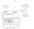
図1は、ホストシステム101と複数のストレージサブシステムを持つストレージシステム100を示す。ストレージシステムには一式のプライマリストレージサブシステム102と複数のセカンダリストレージサブシステム111、112が存在する。ホストシステム101は、入出力が転送される入出力インタフェース103を通してプライマリストレージサブシステム102に結合している。プライマリストレージサブシステム102に入力されたデータ又は情報は、メモリ105を使用してCPU106により処理され、ディスクやRAID又はJBOD(Just a Bunch of Disks)と呼ばれるストレージ媒体に保存される。メモリ
105は、以下に詳細に述べるように、データブロックとこれに付与された順序番号を保存する為のキュー108、最終順序番号を保存する為のレコード109、及び各後続ストレージシステムの最終順序番号を保存する為のテーブル113を収容する。内部バス110は内部データの転送に用いられる。ネットワークインタフェース104は、ネットワークに接続され、セカンダリストレージサブシステム等の他のシステムがデータをコピーし、情報を送受信する為の通信を可能にする。データは、プライマリストレージサブシステム102からセカンダリストレージサブシステム111、112への下り方向にコピーされる。ディスク107からのデータは、プライマリストレージサブシステム102から、ネットワークに結合するネットワークインタフェース104を通して、一つ以上の対象セカンダリストレージサブシステムに流れる。他のストレージシステム(セカンダリストレージサブシステム)は、メモリ105、プロセッサ106、及び記憶媒体107を含めて同様な構成を持つことが望ましい。
FIG. 1 shows a storage system 100 having a host system 101 and a plurality of storage subsystems. The storage system includes a set of
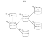
図2は、ホストシステム208、プライマリストレージサブシステム201、及び複数のセカンダリストレージサブシステム202〜205を含むストレージシステム200の論理システム構成を示す概略図である。図1で示すように、プライマリストレージサブシステム201は、ホストシステム208からの入出力が実行されるシステムである。このストレージシステム200では、プライマリストレージサブシステム201のデータは、セカンダリストレージサブシステム202〜205にコピーされる事になっている。ストレージシステム200は、枝分かれ形式のストレージシステム構造になっており、セカンダリストレージサブシステム202、203は第一レベルのセカンダリストレージサブシステムで、セカンダリストレージサブシステム204、205は第二レベルのセカンダリストレージサブシステムである。データは、プライマリストレージサブシステム201から、プライマリストレージサブシステム201に直接後続するシステムとして、第一レベルのセカンダリストレージサブシステム202と203にコピーされる。データは次いで、第一レベルのセカンダリストレージサブシステム202に直接後続するシステムとして、第二レベルのセカンダリストレージサブシステム204と205に、第一レベルのセカンダリストレージサブシステム202からコピーされる。別の言い方をすると、プライマリストレージサブシステム201は、第二ストレージシステム202と203に先行する第一ストレージシステムで、一方、第三ストレージシステム204と205は、第二ストレージシステム202に後続するストレージシステムである。各ストレージシステムは、結合を自動検出するか人為入力によって、結合しているストレージサブシステムを認識している。
FIG. 2 is a schematic diagram showing a logical system configuration of a storage system 200 including a
コピープロセスに於いては、データブロックは、一つのストレージシステムから他のストレージシステムに、ホストシステム208がプライマリストレージサブシステム201に書き込んだ順序通りに、転送される。各データブロックには、プライマリストレージサブシステム201にて、典型的には#1、#2・・・の昇順に、順序番号が付与される。
In the copy process, data blocks are transferred from one storage system to another in the order in which the
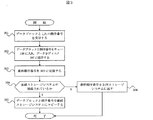
図3は、セカンダリストレージサブシステムの一つなどのストレージサブシステムでのコピープロセスを示す。サブシステムは、データブロックとそれの順序番号をサブシステムに直接接続する先行サブシステムから受信する(ステップ301)。ここで使用されているように、ストレージサブシステム間の関係を記述するのに、便宜上、“先行する”なる用語は“直接に先行する”意味で、“後続する”なる用語は“直接に後続する”意味とする。ステップ302に於いて、データブロックとその順序番号は、書き込み順序を保持する為に、最初に、サブシステムのメモリ中のキュー(例えば、図1のメモリ105内のキュー108を参照)に保存し、データは保存媒体(例えば、図1のディスク107を参照)に保存する。キュー108に収めたデータは、この直後か又は一定時間経過後にディスク107に収める。本データは又、キュー108に収める前にディスク107に格納しても良い。入力データの最終ブロックに伴う最終順序番号は、最終順序番号レコード(例えば、図1のレコード109を参照)に収める(ステップ303)。ストレージサブシステムが、一式以上の後続ストレージサブシステムを持っておれば、入力データとこれの順序番号は、この各後続ストレージサブシステムに転送する(ステップ305)。例えば、図2のストレージサブシステム202は、後続ストレージサブシステム204と205を持ち、ストレージサブシステム201はストレージサブシステム202の先行ストレージサブシステムである。ストレージサブシステムが後続ストレージサブシステムを持っていなければ、受信した最終順序番号は、上りの流れとして先行ストレージサブシステムに戻される(ステップ306)。
FIG. 3 shows a copy process in a storage subsystem such as one of the secondary storage subsystems . The subsystem receives the data block and its sequence number from the preceding subsystem that connects directly to the subsystem (step 301). As used herein, to describe the relationship between storage subsystems, for convenience, the term “preceding” means “directly preceding” and the term “following” is “directly following”. It means “do”. In step 302, the data blocks and their sequence numbers are first stored in a queue in the subsystem's memory (see, for example,
図4は図3のコピープロセスに関連するコピーステータス更新プロセスを説明するフロー図である。コピーステータス更新プロセスは、ストレージサブシステムが後続ストレージサブシステムから最終順序番号を受信したときに開始する(ステップ401)。ストレージサブシステムは、テーブル内の、各後続ストレージサブシステムに対応する最終順序番号欄(図1のテーブル113を参照)を受信した順序番号で更新する(ステップ402)。このテーブル113は、各後続ストレージサブシステムの最終順序番号を保有する。図6はテーブルの一例を示す。ストレージサブシステムは、このテーブル内の最小最終順序番号を検索する(ステップ403)。最小最終順序番号は、ストレージシステムの配下に於ける最古のデータブロックに伴う順序番号である。ステップ403でのテーブル検索は、ストレージサブシステムが後続ストレージサブシステムの一つから最終順序番号を受信し次第、又は、例えば、プライマリストレージサブシステム201又は図2のホストシステム208で事前設定されたある一定時間たってから開始しても良い。ストレージシステムが構成されてコピーが開始した直後の期間に於いては、テーブル113の各最終順序番号欄は、対応する後続ストレージサブシステムの最終順序番号で満たされてはいない、事態が発生し得る。この場合には、本検索は、各欄が対応する後続ストレージサブシステムの最終順序番号で満たされてから、開始される。もとより、ストレージサブシステムがただ一つの後続ストレージサブシステムしか持っていない場合には、本検索及び比較処理は省略することができる。次いで、ストレージサブシステムがプライマリストレージサブシステムの場合には、決定された最小最終順序番号を全ての後続ストレージサブシステムに報告し(ステップ404)、先行ストレージサブシステムが存在すれば、先行ストレージサブシステムに本決定された最小最終順序番号を連絡する(ステップ405)。最小最終順序番号には、これを識別する為にヘッダーを加えても良い。図4に示すステップ404と405はこの順番に実行する必要はなく、この順序は逆転可能なことに注意すること。
FIG. 4 is a flowchart illustrating a copy status update process related to the copy process of FIG. The copy status update process begins when the storage subsystem receives the final sequence number from the subsequent storage subsystem (step 401). The storage subsystem updates the final sequence number column (see table 113 in FIG. 1) corresponding to each subsequent storage subsystem in the table with the received sequence number (step 402). This table 113 holds the final sequence number of each subsequent storage subsystem. FIG. 6 shows an example of the table. The storage subsystem retrieves the minimum final sequence number in this table (step 403). The minimum final sequence number is a sequence number associated with the oldest data block under the storage system. The table lookup in
図5は、コピーステータス更新プロセスでのコピーステータス更新情報に基づいて、データを削除するプロセスを示すフロー図である。データ削除プロセスは、ストレージサブシステムがこれの先行ストレージシサブステムから最小最終順序番号を受信することを契機に開始する(ステップ501)。ストレージサブシステムは、キュー(例えば、図1のキュー108を参照)内のデータブロックで、受信した最小最終順序番号以下の順序番号を持つ全てのデータブロックを削除しても良い(ステップ502)。このデータ削除は、ストレージサブシステムが自らの先行ストレージサブシステムから最小最終順序番号を受信した直後に実行しても、一定時間経過してから実行しても良い。先行ストレージサブシステムを持たないプライマリストレージサブシステム201に於いては、最小最終順序番号は、テーブルを検索して、各後続ストレージサブシステムから受信した最小最終順序番号の最小値を見つけることにより、図4のステップ403で決定される。プライマリストレージサブシステムは、上記で決まった最小最終順序番号以下の順序番号を持つキュー108内のデータブロックを削除できる。何れの場合でも、受信した又は決定した最小最終順序番号は各後続(存在すれば)するセカンダリストレージサブシステムに伝えられ(ステップ503)、本最小最終順序番号がステップ501で受信される。
FIG. 5 is a flowchart showing a process for deleting data based on the copy status update information in the copy status update process. The data deletion process starts when the storage subsystem receives the minimum final sequence number from its predecessor storage system (step 501). The storage subsystem may delete all data blocks with a sequence number less than or equal to the received minimum final sequence number in the data blocks in the queue (see, eg,
本実施例では、コピーステータス更新プロセスとデータ削除プロセスの採用によって、サブシステム障害に於いて、不必要なデータ転送を行うことなく複数ストレージサブシステム間でデータ同期を行う方法が提供される。好都合なことに、プライマリストレージサブシステムのデータバックアップに、何台のストレージサブシステムが配置されているか、又これらのお互いの接続構成に関する全体のストレージシステム構造について、各ストレージサブシステムは認識する必要はない。各ストレージサブシステムは、サブシステム障害時に必要な情報を交換し同期に必要な冗長情報(即ち、最終順序番号を保存しサブシステム障害時のデータ同期に必要なデータをコピーする)を保持するのに、(コピーデータを受け取る)直接先行するストレージサブシステムと、(コピーデータを送信する)直接後続するストレージサブシステムの情報のみを知ればよい。 In this embodiment, by adopting a copy status update process and a data deletion process, a method of synchronizing data between a plurality of storage subsystems without performing unnecessary data transfer in the event of a subsystem failure is provided. Fortunately, it is not necessary for each storage subsystem to know how many storage subsystems are located in the primary storage subsystem's data backup and the overall storage system structure with respect to their connection to each other. Absent. Each storage subsystem exchanges information necessary in the event of a subsystem failure and retains redundant information necessary for synchronization (ie, stores the final sequence number and copies the data necessary for data synchronization in the event of a subsystem failure) In addition, only the information of the storage subsystem that directly precedes (receives copy data) and the storage subsystem that directly follows (transmits copy data) need only be known.
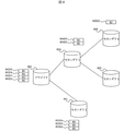
図7はコピープロセス中の各ストレージサブシステムのある瞬間の構成を抽出した構成図である。ホストシステム701はプライマリストレージサブシステム702に接続され、本システム702にデータを書き込む。プライマリストレージサブシステム702のデータは、これに接続されている第一レベルの後続セカンダリストレージサブシステム703と704にコピーされる。第一レベルのセカンダリストレージサブシステム704のデータは、これに接続されている第二レベルの後続セカンダリストレージサブシステム705と706にコピーされる。
FIG. 7 is a configuration diagram in which the configuration at a certain moment of each storage subsystem during the copy process is extracted. The
図7はコピー動作が進行中の各ストレージサブシステムのある瞬間の構成を示す。データブロック70101〜70105は発生順に並んでおり、ホストシステム701で生成されプライマリストレージサブシステム702のキュー108に書き込まれる。図7に示す通り、データブロック70201〜70205は、キュー108内の書き込み済ブロックである。この時点では、データブロック70201〜70204は、セカンダリストレージサブシステム703にコピー済で、データブロック70301〜70304に対応するキューに格納済である。データブロック70201〜70203は、セカンダリストレージサブシステム704にコピー済で、データブロック70401〜70403に対応するキューに格納済である。セカンダリストレージサブシステム704内のデータブロック70401〜70402は、セカンダリストレージサブシステム706にコピー済で、データブロック70601〜70602に対応するキューに格納済である。データブロック70401は、セカンダリストレージサブシステム705にコピー済で、データブロック70501に対応するキューに格納済である。
FIG. 7 shows a configuration at a certain moment of each storage subsystem in which a copy operation is in progress. Data blocks 70101 to 70105 are arranged in the order of occurrence, and are generated by the
最終順序番号レコード109と各後続装置の最終順序番号のテーブル113は、それぞれ70404と70406として、ストレージサブシステム704のみについて示されている。ストレージサブシステム704が後続ストレージサブシステム705、706から最終順序番号(各々、レコード70407内の#1、レコード70408内の#2)を受信すると、本ストレージサブシステム704は、テーブル70406内の最小最終順序番号(レコード70407内の#1)を先行するストレージサブシステム702に報告する。
The final
ストレージサブシステム702に於いては、最小最終順序番号#1はストレージサブシステム704から受け取ったもので、最終順序番号#4(これはストレージサブシステム703での最終順序番号でもある)はストレージサブシステム703から受け取ったものである。ストレージサブシステム702での最小最終順序番号はかくして#1で、本番号#1は後続ストレージサブシステム703、704に報告される。従って、ストレージサブシステム702、703、704は報告された最小最終順序番号(#1)以下の順序番号を持つデータブロックをいつでも削除可能である。次いで、ストレージサブシステム704はこの最小最終順序番号を第二レベルの後続ストレージサブシステム705と706に報告し、ストレージサブシステム705と706は報告された最小最終順序番号(#1)以下の順序番号を持つデータブロックをいつでも削除可能である。
In the
図8は図7で示すデータ状態にデータ削除プロセスを適用した後の各ストレージサブシステムのデータ状態を抽出した構成図である。より具体的には、図8は、各データブロック#(80201、80301、80401、80501、80601)が各対応するストレージサブシステム(802、803、804、805、806)の各キューより削除された後の状態を示す。ストレージサブシステム障害の場合での、ストレージサブシステム間でのデータ同期のメカニズムが示されている。 FIG. 8 is a configuration diagram in which the data state of each storage subsystem after applying the data deletion process to the data state shown in FIG. 7 is extracted. More specifically, in FIG. 8, each data block # (80201, 80301, 80401, 80501, 80601) is deleted from each queue of each corresponding storage subsystem (802, 803, 804, 805, 806). Shown later. A mechanism for data synchronization between storage subsystems in the case of a storage subsystem failure is shown.
一例として、プライマリストレージサブシステム802が障害又は使用不能になったとする。ストレージシステム構成で存在している最終データブロックは、ストレージサブシステム803のデータブロック80304で、順序番号#4(即ち、最大の最終順序番号)を持っている。本順序番号は他の全てのストレージサブシステムに配布される。この配布は、データコピートランザクションに使用されるネットワークを通して、各ストレージサブシステムに配布論理を導入することによって行うか、あるいは各ストレージサブシステムと結合するメカニズムを有するサーバを追加して行うことができる。他のストレージサブシステム(804、805、806)は順序番号#4迄のデータブロックが必要である。ストレージサブシステム804は自らの最終順序番号(#3)をレコード109内に持っており、データブロック80304のみをコピーすればよいことを知っている。このことをネットワーク又はサーバを通して連絡して、データブロック80304のコピー要求が発行され、本データブロックがストレージシステム804にコピーされる。ストレージサブシステム805はデータブロック80304、80303、80302を、ストレージサブシステム806はデータブロック80304、80303を、各々コピーする必要があることを知っている。コピーは、ストレージサブシステム804の場合と同じメカニズムを使用して実行される。
As an example, assume that the
他の例として、ストレージサブシステム804が障害か使用不能だとする。更に、ストレージサブシステム804、806が使用不能だと仮定する。ストレージシステム構成に残っている最終データブロックは、ストレージシステム802の順序番号#5のデータブロック80205である。ストレージサブシステム803はデータブロック80205の、ストレージサブシステム805はデータブロック80202〜80205のコピーをそれぞれ取得する必要がある。
As another example, assume that the
各ストレージサブシステムは、最新データを持っているストレージサブシステムによって同期化される。データブロックはキュー内に冗長に保存され、どのストレージサブシステムが障害になっても、実質的にデータが失われることはない。キューの大きさを減少させる為に、不要になったデータブロックは削除される。 Each storage subsystem is synchronized by the storage subsystem that has the latest data. Data blocks are stored redundantly in the queue and virtually no data is lost if any storage subsystem fails. In order to reduce the size of the queue, data blocks that are no longer needed are deleted.
以上に述べた装置及び方法は、本発明の原理の応用を説明したもので、本発明の精神と請求項で定義された範囲を逸脱する事無く、多数の異なった実装や改変が可能である。従って、本発明の範囲は、これまでの記述を参照して決めるのではなく、添付する請求項の全範囲に従って判断する必要がある。 The apparatus and method described above illustrate the application of the principles of the present invention, and many different implementations and modifications are possible without departing from the spirit of the invention and the scope defined in the claims. . Accordingly, the scope of the invention should be determined according to the full scope of the appended claims, rather than determined by reference to the preceding description.
101 ホスト
102 プライマリストレージサブシステム
103 入出力インタフェース
104 ネットワークインタフェース
105 メモリ
106 CPU
107 ディスク
108 キュー
109 最終順序番号
110 内部バス
111 セカンダリストレージサブシステム(1)
112 セカンダリストレージサブシステム(2)
113 各後続システムの最終順序番号のテーブル
101
107
112 Secondary storage subsystem (2)
113 Table of final sequence numbers for each subsequent system
Claims (1)
前記各ストレージサブシステムはそれぞれ、受信した一つ以上のデータブロックと各データブロックに付与された順序番号を格納するキューを備え、前記各セカンダリストレージサブシステムは、前記プライマリストレージサブシステムに直接、又は、他のセカンダリストレージサブシステムを介して間接的に接続されており、Each of the storage subsystems includes a queue for storing one or more received data blocks and a sequence number assigned to each data block, and each of the secondary storage subsystems directly to the primary storage subsystem or Connected indirectly through other secondary storage subsystems,
前記プライマリストレージサブシステムは、ホストシステムで生成された一つ以上のデータブロックを受信すると、各データブロックに対して順序番号を付与し、該プライマリストレージサブシステムから直接データブロックを受信するストレージサブシステムである後続ストレージサブシステムに対して、前記各データブロックと各データブロックに付与された順序番号を送信し、When the primary storage subsystem receives one or more data blocks generated by the host system, the primary storage subsystem assigns a sequence number to each data block and receives the data block directly from the primary storage subsystem. To each subsequent storage subsystem, the data block and the sequence number assigned to each data block,
前記各セカンダリストレージサブシステムは、前記プライマリストレージサブシステムから送信された各データブロックと各データブロックに付与された順序番号を、前記プライマリストレージサブシステム、又は、他のセカンダリストレージサブシステムのいずれか一つから直接受信し、該セカンダリストレージサブシステムから直接データブロックを受信するストレージサブシステムである後続ストレージサブシステムに対して、前記各データブロックと各データブロックに付与された順序番号を送信し、Each of the secondary storage subsystems is configured to display each data block transmitted from the primary storage subsystem and a sequence number assigned to each data block, either of the primary storage subsystem or another secondary storage subsystem. Each data block and the sequence number assigned to each data block are transmitted to the subsequent storage subsystem, which is a storage subsystem that receives the data block directly from the secondary storage subsystem.
該セカンダリストレージサブシステムが受信した最新のデータブロックに付与された順序番号と該セカンダリストレージサブシステムの後続ストレージサブシステムから受信した順序番号の中で最も古いデータブロックに付与された順序番号を、該セカンダリストレージサブシステムに直接データブロックを送信するストレージサブシステムである先行ストレージサブシステムに対して送信し、The sequence number assigned to the latest data block received by the secondary storage subsystem and the sequence number assigned to the oldest data block among the sequence numbers received from the subsequent storage subsystem of the secondary storage subsystem are Send to the preceding storage subsystem, which is the storage subsystem that sends the data blocks directly to the secondary storage subsystem,
前記プライマリストレージサブシステムは、該プライマリストレージサブシステムの後続ストレージサブシステムから受信した順序番号の中から最も古いデータブロックに付与された順序番号を検索して、該順序番号を該後続ストレージサブシステムに報告し、The primary storage subsystem searches the sequence number assigned to the oldest data block from the sequence numbers received from the subsequent storage subsystem of the primary storage subsystem, and sends the sequence number to the subsequent storage subsystem. Report,
前記各セカンダリストレージサブシステムは、該セカンダリストレージサブシステムの先行ストレージサブシステムから、前記プライマリストレージサブシステムにより検索された順序番号を受信し、当該順序番号を該セカンダリストレージサブシステムの後続ストレージサブシステムに報告することを特徴とするストレージシステム。Each secondary storage subsystem receives the sequence number retrieved by the primary storage subsystem from the preceding storage subsystem of the secondary storage subsystem, and sends the sequence number to the subsequent storage subsystem of the secondary storage subsystem. A storage system characterized by reporting.
Applications Claiming Priority (1)
| Application Number | Priority Date | Filing Date | Title |
|---|---|---|---|
| US10/792,550 US7111139B2 (en) | 2004-03-02 | 2004-03-02 | Data synchronization of multiple remote storage |
Publications (3)
| Publication Number | Publication Date |
|---|---|
| JP2005301976A JP2005301976A (en) | 2005-10-27 |
| JP2005301976A5 JP2005301976A5 (en) | 2007-01-25 |
| JP4108074B2 true JP4108074B2 (en) | 2008-06-25 |
Family
ID=34911878
Family Applications (1)
| Application Number | Title | Priority Date | Filing Date |
|---|---|---|---|
| JP2004307582A Expired - Fee Related JP4108074B2 (en) | 2004-03-02 | 2004-10-22 | Data synchronization with multiple remote storage |
Country Status (2)
| Country | Link |
|---|---|
| US (1) | US7111139B2 (en) |
| JP (1) | JP4108074B2 (en) |
Families Citing this family (87)
| Publication number | Priority date | Publication date | Assignee | Title |
|---|---|---|---|---|
| US7756825B2 (en) * | 2003-07-31 | 2010-07-13 | Microsoft Corporation | Synchronization peer participant model |
| US7440985B2 (en) * | 2003-07-31 | 2008-10-21 | Microsoft Corporation | Filtered replication of data stores |
| JP2007510756A (en) * | 2003-11-12 | 2007-04-26 | ファルマシア・アンド・アップジョン・カンパニー・エルエルシー | Compositions of cyclooxygenase-2 selective inhibitors and neurotrophic factor modulators for treating central nervous system mediated disorders |
| US8359429B1 (en) | 2004-11-08 | 2013-01-22 | Symantec Operating Corporation | System and method for distributing volume status information in a storage system |
| US7409575B2 (en) * | 2004-12-31 | 2008-08-05 | Intel Corporation | Recovery of computer systems |
| US7924857B2 (en) * | 2006-01-05 | 2011-04-12 | Agere Systems Inc. | Methods and apparatus for reorganizing cells buffered after transmission |
| US7853839B2 (en) * | 2006-04-04 | 2010-12-14 | Qualcomm Incorporated | Method and apparatus for verifying the correctness of FTAP data packets received on the FLO waveform |
| US7890646B2 (en) * | 2006-04-27 | 2011-02-15 | Microsoft Corporation | Synchronization orchestration |
| US7805408B2 (en) * | 2006-06-09 | 2010-09-28 | Microsoft Corporation | Unified mechanism for presenting and resolving grouped synchronization conflicts |
| US7539827B2 (en) * | 2006-07-19 | 2009-05-26 | Microsoft Corporation | Synchronization of change-tracked data store with data store having limited or no change tracking |
| JP2008269179A (en) * | 2007-04-18 | 2008-11-06 | Hitachi Ltd | Computer system, management terminal, storage device, and cipher management method |
| US7991910B2 (en) | 2008-11-17 | 2011-08-02 | Amazon Technologies, Inc. | Updating routing information based on client location |
| US8028090B2 (en) | 2008-11-17 | 2011-09-27 | Amazon Technologies, Inc. | Request routing utilizing client location information |
| WO2009013830A1 (en) * | 2007-07-26 | 2009-01-29 | Fujitsu Limited | Storage part control device, storage part control system, storage part control program, and computer-readable recording medium having recorded that program |
| JP5026309B2 (en) * | 2008-03-06 | 2012-09-12 | 株式会社日立製作所 | Backup data management system and backup data management method |
| US8606996B2 (en) | 2008-03-31 | 2013-12-10 | Amazon Technologies, Inc. | Cache optimization |
| US8447831B1 (en) | 2008-03-31 | 2013-05-21 | Amazon Technologies, Inc. | Incentive driven content delivery |
| US8321568B2 (en) | 2008-03-31 | 2012-11-27 | Amazon Technologies, Inc. | Content management |
| US7962597B2 (en) | 2008-03-31 | 2011-06-14 | Amazon Technologies, Inc. | Request routing based on class |
| US7970820B1 (en) | 2008-03-31 | 2011-06-28 | Amazon Technologies, Inc. | Locality based content distribution |
| US8601090B1 (en) | 2008-03-31 | 2013-12-03 | Amazon Technologies, Inc. | Network resource identification |
| US9407681B1 (en) | 2010-09-28 | 2016-08-02 | Amazon Technologies, Inc. | Latency measurement in resource requests |
| US8122098B1 (en) | 2008-11-17 | 2012-02-21 | Amazon Technologies, Inc. | Managing content delivery network service providers by a content broker |
| US8073940B1 (en) | 2008-11-17 | 2011-12-06 | Amazon Technologies, Inc. | Managing content delivery network service providers |
| US8688837B1 (en) | 2009-03-27 | 2014-04-01 | Amazon Technologies, Inc. | Dynamically translating resource identifiers for request routing using popularity information |
| US8412823B1 (en) | 2009-03-27 | 2013-04-02 | Amazon Technologies, Inc. | Managing tracking information entries in resource cache components |
| US8756341B1 (en) | 2009-03-27 | 2014-06-17 | Amazon Technologies, Inc. | Request routing utilizing popularity information |
| JP5439014B2 (en) * | 2009-04-10 | 2014-03-12 | 株式会社日立製作所 | Data processing system, processing method thereof, and computer |
| US8782236B1 (en) | 2009-06-16 | 2014-07-15 | Amazon Technologies, Inc. | Managing resources using resource expiration data |
| US8397073B1 (en) | 2009-09-04 | 2013-03-12 | Amazon Technologies, Inc. | Managing secure content in a content delivery network |
| US8433771B1 (en) * | 2009-10-02 | 2013-04-30 | Amazon Technologies, Inc. | Distribution network with forward resource propagation |
| US9454325B2 (en) * | 2009-11-04 | 2016-09-27 | Broadcom Corporation | Method and system for offline data access on computer systems |
| US9495338B1 (en) | 2010-01-28 | 2016-11-15 | Amazon Technologies, Inc. | Content distribution network |
| US10958501B1 (en) | 2010-09-28 | 2021-03-23 | Amazon Technologies, Inc. | Request routing information based on client IP groupings |
| US10097398B1 (en) | 2010-09-28 | 2018-10-09 | Amazon Technologies, Inc. | Point of presence management in request routing |
| US8468247B1 (en) | 2010-09-28 | 2013-06-18 | Amazon Technologies, Inc. | Point of presence management in request routing |
| US9003035B1 (en) | 2010-09-28 | 2015-04-07 | Amazon Technologies, Inc. | Point of presence management in request routing |
| US9712484B1 (en) | 2010-09-28 | 2017-07-18 | Amazon Technologies, Inc. | Managing request routing information utilizing client identifiers |
| US8452874B2 (en) | 2010-11-22 | 2013-05-28 | Amazon Technologies, Inc. | Request routing processing |
| US10467042B1 (en) | 2011-04-27 | 2019-11-05 | Amazon Technologies, Inc. | Optimized deployment based upon customer locality |
| US10623408B1 (en) | 2012-04-02 | 2020-04-14 | Amazon Technologies, Inc. | Context sensitive object management |
| US9154551B1 (en) | 2012-06-11 | 2015-10-06 | Amazon Technologies, Inc. | Processing DNS queries to identify pre-processing information |
| US9323577B2 (en) | 2012-09-20 | 2016-04-26 | Amazon Technologies, Inc. | Automated profiling of resource usage |
| US10205698B1 (en) | 2012-12-19 | 2019-02-12 | Amazon Technologies, Inc. | Source-dependent address resolution |
| US9559897B2 (en) | 2012-12-21 | 2017-01-31 | Brocade Communications Systems, Inc. | Device ID assignment in a system of devices |
| US9460178B2 (en) * | 2013-01-25 | 2016-10-04 | Dell Products L.P. | Synchronized storage system operation |
| US9853889B2 (en) | 2013-05-20 | 2017-12-26 | Brocade Communications Systems, Inc. | Broadcast and multicast traffic reduction in stacking systems |
| US9313102B2 (en) | 2013-05-20 | 2016-04-12 | Brocade Communications Systems, Inc. | Configuration validation in a mixed node topology |
| US9294391B1 (en) | 2013-06-04 | 2016-03-22 | Amazon Technologies, Inc. | Managing network computing components utilizing request routing |
| US10284499B2 (en) | 2013-08-22 | 2019-05-07 | Arris Enterprises Llc | Dedicated control path architecture for systems of devices |
| US9185049B2 (en) | 2013-10-31 | 2015-11-10 | Brocade Communications Systems, Inc. | Techniques for simplifying stacking trunk creation and management |
| US9577932B2 (en) | 2014-02-12 | 2017-02-21 | Brocade Communications Systems, Inc. | Techniques for managing ternary content-addressable memory (TCAM) resources in heterogeneous systems |
| US9692695B2 (en) | 2014-03-27 | 2017-06-27 | Brocade Communications Systems, Inc. | Techniques for aggregating hardware routing resources in a multi-packet processor networking system |
| US9692652B2 (en) * | 2014-04-03 | 2017-06-27 | Brocade Communications Systems, Inc. | Framework for reliably communicating port information in a system of devices |
| US10091059B2 (en) | 2014-12-16 | 2018-10-02 | Arris Enterprises Llc | Handling connections between network devices that support multiple port communication modes |
| US10097448B1 (en) | 2014-12-18 | 2018-10-09 | Amazon Technologies, Inc. | Routing mode and point-of-presence selection service |
| US10033627B1 (en) | 2014-12-18 | 2018-07-24 | Amazon Technologies, Inc. | Routing mode and point-of-presence selection service |
| US10091096B1 (en) | 2014-12-18 | 2018-10-02 | Amazon Technologies, Inc. | Routing mode and point-of-presence selection service |
| JP6282989B2 (en) * | 2015-02-16 | 2018-02-21 | 日本電信電話株式会社 | Database system and master / slave determination method thereof |
| US10225326B1 (en) | 2015-03-23 | 2019-03-05 | Amazon Technologies, Inc. | Point of presence based data uploading |
| US9819567B1 (en) | 2015-03-30 | 2017-11-14 | Amazon Technologies, Inc. | Traffic surge management for points of presence |
| US9832141B1 (en) | 2015-05-13 | 2017-11-28 | Amazon Technologies, Inc. | Routing based request correlation |
| US10097566B1 (en) | 2015-07-31 | 2018-10-09 | Amazon Technologies, Inc. | Identifying targets of network attacks |
| US9774619B1 (en) | 2015-09-24 | 2017-09-26 | Amazon Technologies, Inc. | Mitigating network attacks |
| US10270878B1 (en) | 2015-11-10 | 2019-04-23 | Amazon Technologies, Inc. | Routing for origin-facing points of presence |
| US10049051B1 (en) | 2015-12-11 | 2018-08-14 | Amazon Technologies, Inc. | Reserved cache space in content delivery networks |
| US10257307B1 (en) | 2015-12-11 | 2019-04-09 | Amazon Technologies, Inc. | Reserved cache space in content delivery networks |
| US10348639B2 (en) | 2015-12-18 | 2019-07-09 | Amazon Technologies, Inc. | Use of virtual endpoints to improve data transmission rates |
| US10075551B1 (en) | 2016-06-06 | 2018-09-11 | Amazon Technologies, Inc. | Request management for hierarchical cache |
| US10110694B1 (en) | 2016-06-29 | 2018-10-23 | Amazon Technologies, Inc. | Adaptive transfer rate for retrieving content from a server |
| US9992086B1 (en) | 2016-08-23 | 2018-06-05 | Amazon Technologies, Inc. | External health checking of virtual private cloud network environments |
| US10033691B1 (en) | 2016-08-24 | 2018-07-24 | Amazon Technologies, Inc. | Adaptive resolution of domain name requests in virtual private cloud network environments |
| US10353735B2 (en) | 2016-09-30 | 2019-07-16 | International Business Machines Corporation | Computing system including independent coupling facilities maintaining equivalency based on sequence values |
| US10469513B2 (en) | 2016-10-05 | 2019-11-05 | Amazon Technologies, Inc. | Encrypted network addresses |
| US10372499B1 (en) | 2016-12-27 | 2019-08-06 | Amazon Technologies, Inc. | Efficient region selection system for executing request-driven code |
| US10831549B1 (en) | 2016-12-27 | 2020-11-10 | Amazon Technologies, Inc. | Multi-region request-driven code execution system |
| US10938884B1 (en) | 2017-01-30 | 2021-03-02 | Amazon Technologies, Inc. | Origin server cloaking using virtual private cloud network environments |
| US10771315B2 (en) * | 2017-02-14 | 2020-09-08 | Futurewei Technologies, Inc. | High availability using multiple network elements |
| US10503613B1 (en) | 2017-04-21 | 2019-12-10 | Amazon Technologies, Inc. | Efficient serving of resources during server unavailability |
| US11075987B1 (en) | 2017-06-12 | 2021-07-27 | Amazon Technologies, Inc. | Load estimating content delivery network |
| US10447648B2 (en) | 2017-06-19 | 2019-10-15 | Amazon Technologies, Inc. | Assignment of a POP to a DNS resolver based on volume of communications over a link between client devices and the POP |
| US10742593B1 (en) | 2017-09-25 | 2020-08-11 | Amazon Technologies, Inc. | Hybrid content request routing system |
| US10852966B1 (en) * | 2017-10-18 | 2020-12-01 | EMC IP Holding Company, LLC | System and method for creating mapped RAID group during expansion of extent pool |
| US10852951B1 (en) * | 2017-10-18 | 2020-12-01 | EMC IP Holding Company, LLC | System and method for improving I/O performance by introducing extent pool level I/O credits and user I/O credits throttling on Mapped RAID |
| US10592578B1 (en) | 2018-03-07 | 2020-03-17 | Amazon Technologies, Inc. | Predictive content push-enabled content delivery network |
| US10862852B1 (en) | 2018-11-16 | 2020-12-08 | Amazon Technologies, Inc. | Resolution of domain name requests in heterogeneous network environments |
| US11025747B1 (en) | 2018-12-12 | 2021-06-01 | Amazon Technologies, Inc. | Content request pattern-based routing system |
Family Cites Families (11)
| Publication number | Priority date | Publication date | Assignee | Title |
|---|---|---|---|---|
| US5280611A (en) * | 1991-11-08 | 1994-01-18 | International Business Machines Corporation | Method for managing database recovery from failure of a shared store in a system including a plurality of transaction-based systems of the write-ahead logging type |
| US5682513A (en) * | 1995-03-31 | 1997-10-28 | International Business Machines Corporation | Cache queue entry linking for DASD record updates |
| US6330568B1 (en) | 1996-11-13 | 2001-12-11 | Pumatech, Inc. | Synchronization of databases |
| US6578120B1 (en) * | 1997-06-24 | 2003-06-10 | International Business Machines Corporation | Synchronization and resynchronization of loosely-coupled copy operations between a primary and a remote secondary DASD volume under concurrent updating |
| US6324654B1 (en) * | 1998-03-30 | 2001-11-27 | Legato Systems, Inc. | Computer network remote data mirroring system |
| US6574709B1 (en) * | 1999-09-30 | 2003-06-03 | International Business Machine Corporation | System, apparatus, and method providing cache data mirroring to a data storage system |
| US6604205B1 (en) * | 2000-02-07 | 2003-08-05 | Hewlett-Packard Development Co., L.P. | System and method for state synchronization |
| DE60039033D1 (en) * | 2000-05-25 | 2008-07-10 | Hitachi Ltd | Storage system for confirming data synchronization during asynchronous remote copying |
| JP2002358222A (en) | 2001-06-04 | 2002-12-13 | Hitachi Ltd | Data dual system and method |
| US7139932B2 (en) | 2002-01-03 | 2006-11-21 | Hitachi, Ltd. | Data synchronization of multiple remote storage after remote copy suspension |
| US6842825B2 (en) * | 2002-08-07 | 2005-01-11 | International Business Machines Corporation | Adjusting timestamps to preserve update timing information for cached data objects |
-
2004
- 2004-03-02 US US10/792,550 patent/US7111139B2/en not_active Expired - Fee Related
- 2004-10-22 JP JP2004307582A patent/JP4108074B2/en not_active Expired - Fee Related
Also Published As
| Publication number | Publication date |
|---|---|
| US7111139B2 (en) | 2006-09-19 |
| JP2005301976A (en) | 2005-10-27 |
| US20050198453A1 (en) | 2005-09-08 |
Similar Documents
| Publication | Publication Date | Title |
|---|---|---|
| JP4108074B2 (en) | Data synchronization with multiple remote storage | |
| EP1481324B1 (en) | Producing a mirrored copy using incremental-divergence | |
| US7139932B2 (en) | Data synchronization of multiple remote storage after remote copy suspension | |
| US7225307B2 (en) | Apparatus, system, and method for synchronizing an asynchronous mirror volume using a synchronous mirror volume | |
| US7562103B2 (en) | Disaster recovery processing method and apparatus and storage unit for the same | |
| US6745303B2 (en) | Data synchronization of multiple remote storage | |
| JP4477950B2 (en) | Remote copy system and storage device system | |
| US7120824B2 (en) | Method, apparatus and program storage device for maintaining data consistency and cache coherency during communications failures between nodes in a remote mirror pair | |
| US7673173B2 (en) | System and program for transmitting input/output requests from a first controller to a second controller | |
| JP4796854B2 (en) | Measures against data overflow of intermediate volume in differential remote copy | |
| US7254685B1 (en) | Method for maintaining high performance while preserving relative write I/O ordering for a semi-synchronous remote replication solution | |
| JP2005165618A (en) | Control method for storage system, storage system, and storage device | |
| JP2002149499A (en) | Remote copy system with integrity of data | |
| JP6931081B2 (en) | Data backup system, relay site storage, data backup method, and relay site storage control program | |
| JP2005309793A (en) | Data processing system | |
| US8250240B2 (en) | Message conversion method and message conversion system | |
| US20090177916A1 (en) | Storage system, controller of storage system, control method of storage system | |
| JP2006285336A (en) | Storage, storage system, and control method thereof | |
| US8032726B2 (en) | Remote copy system | |
| US7302604B2 (en) | Remote management commands in a mass storage system | |
| JP4452494B2 (en) | Data synchronization method after stopping remote copy on multiple remote storages | |
| JP2004272884A5 (en) | ||
| JP4721057B2 (en) | Data management system, data management method, and data management program |
Legal Events
| Date | Code | Title | Description |
|---|---|---|---|
| RD04 | Notification of resignation of power of attorney |
Free format text: JAPANESE INTERMEDIATE CODE: A7424 Effective date: 20060425 |
|
| A521 | Request for written amendment filed |
Free format text: JAPANESE INTERMEDIATE CODE: A523 Effective date: 20061024 Free format text: JAPANESE INTERMEDIATE CODE: A821 Effective date: 20061024 |
|
| A621 | Written request for application examination |
Free format text: JAPANESE INTERMEDIATE CODE: A621 Effective date: 20061024 |
|
| A871 | Explanation of circumstances concerning accelerated examination |
Free format text: JAPANESE INTERMEDIATE CODE: A871 Effective date: 20061024 |
|
| RD02 | Notification of acceptance of power of attorney |
Free format text: JAPANESE INTERMEDIATE CODE: A7422 Effective date: 20061024 |
|
| A975 | Report on accelerated examination |
Free format text: JAPANESE INTERMEDIATE CODE: A971005 Effective date: 20061127 |
|
| A521 | Request for written amendment filed |
Free format text: JAPANESE INTERMEDIATE CODE: A523 Effective date: 20061130 |
|
| A871 | Explanation of circumstances concerning accelerated examination |
Free format text: JAPANESE INTERMEDIATE CODE: A871 Effective date: 20061130 |
|
| A975 | Report on accelerated examination |
Free format text: JAPANESE INTERMEDIATE CODE: A971005 Effective date: 20070219 |
|
| A131 | Notification of reasons for refusal |
Free format text: JAPANESE INTERMEDIATE CODE: A131 Effective date: 20070226 |
|
| A521 | Request for written amendment filed |
Free format text: JAPANESE INTERMEDIATE CODE: A523 Effective date: 20070418 |
|
| A131 | Notification of reasons for refusal |
Free format text: JAPANESE INTERMEDIATE CODE: A131 Effective date: 20070608 |
|
| A521 | Request for written amendment filed |
Free format text: JAPANESE INTERMEDIATE CODE: A523 Effective date: 20070725 |
|
| RD04 | Notification of resignation of power of attorney |
Free format text: JAPANESE INTERMEDIATE CODE: A7424 Effective date: 20070731 |
|
| A131 | Notification of reasons for refusal |
Free format text: JAPANESE INTERMEDIATE CODE: A131 Effective date: 20071113 |
|
| A521 | Request for written amendment filed |
Free format text: JAPANESE INTERMEDIATE CODE: A523 Effective date: 20071225 |
|
| TRDD | Decision of grant or rejection written | ||
| A01 | Written decision to grant a patent or to grant a registration (utility model) |
Free format text: JAPANESE INTERMEDIATE CODE: A01 Effective date: 20080326 |
|
| A61 | First payment of annual fees (during grant procedure) |
Free format text: JAPANESE INTERMEDIATE CODE: A61 Effective date: 20080401 |
|
| FPAY | Renewal fee payment (event date is renewal date of database) |
Free format text: PAYMENT UNTIL: 20110411 Year of fee payment: 3 |
|
| R150 | Certificate of patent or registration of utility model |
Ref document number: 4108074 Country of ref document: JP Free format text: JAPANESE INTERMEDIATE CODE: R150 Free format text: JAPANESE INTERMEDIATE CODE: R150 |
|
| FPAY | Renewal fee payment (event date is renewal date of database) |
Free format text: PAYMENT UNTIL: 20120411 Year of fee payment: 4 |
|
| FPAY | Renewal fee payment (event date is renewal date of database) |
Free format text: PAYMENT UNTIL: 20120411 Year of fee payment: 4 |
|
| FPAY | Renewal fee payment (event date is renewal date of database) |
Free format text: PAYMENT UNTIL: 20130411 Year of fee payment: 5 |
|
| FPAY | Renewal fee payment (event date is renewal date of database) |
Free format text: PAYMENT UNTIL: 20140411 Year of fee payment: 6 |
|
| R250 | Receipt of annual fees |
Free format text: JAPANESE INTERMEDIATE CODE: R250 |
|
| R250 | Receipt of annual fees |
Free format text: JAPANESE INTERMEDIATE CODE: R250 |
|
| R250 | Receipt of annual fees |
Free format text: JAPANESE INTERMEDIATE CODE: R250 |
|
| R250 | Receipt of annual fees |
Free format text: JAPANESE INTERMEDIATE CODE: R250 |
|
| R250 | Receipt of annual fees |
Free format text: JAPANESE INTERMEDIATE CODE: R250 |
|
| R250 | Receipt of annual fees |
Free format text: JAPANESE INTERMEDIATE CODE: R250 |
|
| LAPS | Cancellation because of no payment of annual fees |