JP4106124B2 - Automatic fish tracking tracking sonar - Google Patents
Automatic fish tracking tracking sonar Download PDFInfo
- Publication number
- JP4106124B2 JP4106124B2 JP12308298A JP12308298A JP4106124B2 JP 4106124 B2 JP4106124 B2 JP 4106124B2 JP 12308298 A JP12308298 A JP 12308298A JP 12308298 A JP12308298 A JP 12308298A JP 4106124 B2 JP4106124 B2 JP 4106124B2
- Authority
- JP
- Japan
- Prior art keywords
- fish
- center
- target
- main area
- school
- Prior art date
- Legal status (The legal status is an assumption and is not a legal conclusion. Google has not performed a legal analysis and makes no representation as to the accuracy of the status listed.)
- Expired - Fee Related
Links
Images


Description
【0001】
【発明の属する技術分野】
本発明は、スキャニングソナーに関し、特に標的を自動追尾できる機能を有する自動魚群追尾スキャニングソナーに関する。
【0002】
【従来の技術】
漁撈では魚群の位置を知るだけでなく、網を仕掛けるためにその魚群がどの方向にどれだけの速度で移動しているかを知ることが肝要であり、そのためには標的と定めた魚群を自動追尾する機能を備えた装置が必要である。その種のものとして例えば実公平7-19020号の「標的追尾方式のスキャニングソナー」があり、その概要を次に述べる。
【0003】
まず、モニターに表示されている探知画像を見て、標的とする魚群で表示密度の最も高い箇所を標的中心としてイベントマークを付す。これにより、そのイベントマークを中心とする追尾検出用のエリアが設定され、そのイベントマークにビーム中心が向くようにしてビームスキャンが行われる。このビームスキャンで得られた検出信号に対し、前記エリアの中でレベルの最も高い箇所が選出され、その箇所にイベントマークが付け替えられ、そのイベントマークに対して新たに追尾検出領域が設定される。そして新たに決定したイベントマークに向けてビームスキャンする動作を繰り返すことにより、標的中心を自動追尾している。
【0004】
尚、スキャニングソナーとは、図1に示すように、船底に取り付けた送受波器1より海底に向け、全方位方向に超音波を送波し、それによるエコーを送受波器1で受波する際、図示したような指向角の鋭い受波ビームRを形成し、その受波ビームを海面に対してθの角度(この角度をチルト角という)を保ちながら旋回(水平スキャン)すれば、受波ビームRは円錐体表面Uに沿ってスキャンする。これにより、円錐体表面上に位置していた魚群等よりのエコーが近い物から順に検出される。ここでチルト角θを標的の向きにロックすれば標的を追尾できる。
【0005】
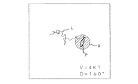
この公報のスキャニングソナーでは、標的の軌跡表示や移動速度については述べられていないが、一定時刻毎に標的の位置をプロットすることにより、軌跡表示、移動方向および移動速度を知ることが可能であり、既にそのようなシステムが実用化されている。図2はそのようなシステムの軌跡表示例を示している。画面中央が自船位置となり、Xが標的に定めた魚群の像である。Lはその魚群Xの軌跡である。魚群Xの中央に描いた魚マークPの向きが現在の魚群Xの移動方向を示す。画面右下には、魚群Xの移動速度と移動方位が示される。この軌跡Lを見ると魚群Xはさまよっているかのように移動しているが、実際にそのような動きをしているのではなく、このように表示される原因は自船の船体動揺によるものである。この軌跡Lからわかるように、マークPの向きも刻々と変わる。
【0006】
【発明が解決しようとする課題】
このように紛らわしい表示がなされるため、魚群Xの真の移動軌跡や移動方向を知ることはできない。船体の動揺を検出し、検出したエコー信号を補正して動揺を排除することも可能であるが、船体における3方向の動揺を検出してエコー信号を補正することは技術的に困難であり、又、ビーム角度の少しの変化でエコーが微妙にゆらぐため仮に完全な補正が行えたとしても動揺に伴う影響を完全に排除することはできない。
【0007】
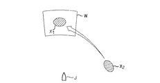
更に前記の公報では、魚群Xの中心を検出する際に、信号レベルの最大箇所としていたが、検出信号が異常に強く、信号が飽和してしまったような場合には、魚群Xの中心を正確に検出できなくなり、そのために適確な標的追尾が行えなくなる。例えば、図3において、Jは自船、Wは上述したエリアを示し、このエリアW内で追尾していた魚群X1を見失うと、標的対象が魚群X2へ突然移行してしまい、図4に示すように、魚群X2を追尾対象にしてしまう。その場合、図5に示すように、標的をX2からX1に再指定する必要があり、その場合、それまでの軌跡Lがクリアされてしまい、最初からやり直す必要があった。
【0008】
本発明は、上述した課題を解決するためになされたものであり、標的の移動速度、移動方向並びに移動軌跡を適確に知ることができ、かつ、標的の追尾能力の高いスキャニングソナーを提供することを目的とする。
【0009】
【課題を解決するための手段】
上述した従来のシステムでは、検出結果をそのまま軌跡として表示するために紛らわしい表示が出力される。船体の動揺周期は一般に数秒程度で短い。従って所定時間が経過する毎に、もしくは魚群が所定距離を移動する毎に、画面に出力するようにすれば、つまり、検出データを出力しない不感帯を設ければ短時間内で生じるような動揺に伴う偽りの検出データを排除することができる。
【0010】
不感帯として固定の時間を設定すると、魚群の移動速度が小さいとき、その時間が経過する毎に、魚群の位置はほぼ正確に表示されるが、データ検出時に船体が動揺しておれば、やはり魚群の移動方向が定まらず、正確な移動方向が表示されない。そこで、本発明では、請求項2で示したように、標的中心が一定の時間を経過する毎に、標的中心の最初と最後の位置データから標的の移動速度もしくは移動方位のいずれか一つを表示している。
【0011】
標的移動速度は、移動距離と移動に要した時間で算出されるが、距離と時間が短い程つまり、瞬時の速度は変化が激しく安定した結果が得られない。そこで、瞬時速度を所定時間で平均化した速度を用いれば安定し見やすい結果となる。ここでは、移動に要した時間を所定時間以上に確保することにより平均化の効果を持たせた。移動方位に関してもこれと同様の手段を用いた。
【0012】
魚群が移動元点から直線で一定の距離を移動したことを知る手段として、請求項1では、後で詳しく参照する図15に示すように、標的Xaの中心が中央に位置するように所定サイズのエリアW1を設定し、そのエリアW1から標的中央が外れたかを検出している。
【0013】
図6に示したように、自船Jから魚群Xが大きさを変えずに離れていく場合、受波ビームRのビーム径も広がっていくため、同一の魚群Xであってもその像Hは、自船Jから離れるに従い大きく表示される。従って、一定の距離を移動したことを知る手段として設けたエリアWのサイズも請求項3に示したように大きくする必要がある。
【0014】
図15に示したエリアW1は、魚群Xaの移動距離を知るためのものであるから、魚群Xaが移動してもエリアは移動しない。従って、そのエリアW1内でXbで示した魚群を追尾するには、その移動に追随して移動する追尾用のサブエリアwを設けている。これと区別するために先のエリアW1をメインエリアと称す。
【0015】
メインエリアW1にある魚群エコーを、得られたレベルで2値化する。2値化されたデータの塊を膨張し(欠落している箇所を穴埋め)、標的候補つまりデータの塊が複数個存在する場合は、特徴抽出により、データの塊を1個に絞る。データの塊を1個に絞った後は、そのデータの塊の重心を求め、標的の中心とする。
【0016】
ここで標的エコー選択と誤認追尾防止の手段について述べる。
(標的エコー選択)
魚群エコーを識別する為のパラメータとして以下を設定する。
面積:A、距離:L、強度:S、縦横比:R
重みを付けて加算したものを特徴量として定義する。
特徴量P=αA+βL+ηS+γR
例えば重みを以下の通り設定し、
判定式1では、α:β:η:γ=1:4:2:1
判定式2では、α:β:η:γ=4:3:2:1
標的に適した判定式を選択し、特徴量Pを得る。
特徴量の最も高い値を選択する。
(誤認追尾防止)
標的エコーは時に受信されず途切れる場合も存在する。この場合、他の標的を誤認追尾させないためのフィルタを設けた。
1.速度制限フィルタ
標的を見失い他の標的を誤認追尾すると、移った瞬間速度は大きな値を示す。限界速度を設けることにより、誤認追尾を防ぐことができる。
2.加速度制限フィルタ
標的なら一定の速度で移動しているのが常であり、速度の変化つまり加速度は一定以下になるのが通常である。従って限界加速度を設けることにより誤認追尾を防ぐことができる。
【0017】
本発明では、魚群の規模を数値化するために、魚量値を求めており、その算出法については後で数式を用いて詳しく説明する。
【0018】
【発明の実施の形態】
図7は、本発明のスキャニングソナーの1実施形態を示した制御ブロック図である。1は、多数の超音波振動子を円筒状に配列してなる送受波器であり、2は送受波器1の送波器を励振する駆動回路である。3は、縦方向の超音波振動子列で受波された各信号に対してそれぞれ所定の遅延を設定することにより、所望のチルト角を有する受波ビームを形成する垂直ビーム合成回路である。4は、垂直ビーム合成回路3で形成されたビームから所望の方位のビームを得るために、横方向の超音波振動子列で得られた信号に対して所定の遅延を設定する水平ビーム形成回路である。この垂直ビーム合成および水平ビーム合成により図1に示した鋭い指向角の受波ビームRが形成される。
【0019】
5は、水平ビーム形成回路4より得られた受波ビームの信号を極座標系から直交座標系に変換する座標変換回路であり、6は、前記信号をA/D変換するA/D器であり、そのA/D変換された信号は画面記憶メモリ7に格納される。その画面記憶メモリ7の信号は、信号加算器8を通じてモニター9に送出され、画面表示される。以上の回路構成は一般のスキャニングソナーの構成である。
【0020】
10は、前記構成に対して本発明の機能を実施させるためのCPUである。信号加算器8においては、画面記憶メモリ7からの1画面のデータに対して後述するメインエリアの枠が重ねて表示され、そのデータはモニター9に送出されると共に魚群認識部11に送出される。この魚群認識部11では後述するように、魚群を認識する。12は、認識された魚群が複数個ある場合、その中から標的としている魚群を選出する魚群選択部である。標的とした魚群のデータが標的中心検出部13に送出されることにより、この標的中心検出部13では前述したように魚群の中心が重心位置から求められる。14は、自船位置から魚群の中心までの距離を演算する距離演算部である。15は、前記の距離からサブエリアのサイズを決めると共に、魚群の中心位置からサブエリアの位置を決めるサブエリアサイズ・位置設定部であり、カーソルにより、随意の位置に設定することも可能である。16は、現在の魚群中心の位置データから次回の受波ビーム形成時のチルト角を演算するチルト角演算部であり、求められたチルト角は垂直ビーム合成回路3に送出される。
【0021】
17は、その魚群中心がメインエリア外にあるかを判定するメインエリア外判定部である。18は、魚群中心がメインエリア外にあるとき、サブエリアサイズ・位置設定部15で設定されたデータに基づき新たにメインエリアを設定するメインエリア設定部であり、カーソルによりサブエリアが設定されたとは、それと同サイズのメインエリアを設定する。
【0022】
19は、標的中心の移動から魚群の移動速度を演算する標的速度演算部である。20は、求められた移動速度を、外部から入力される船速および自船の進行方位で補正し、魚群の真の移動速度(対地速度)を演算する速度補正部である。21は、選択された魚群の魚量値を演算する魚量値演算部であり、22は、魚群中心の移動からその軌跡を求める軌跡作成部であり、これらのデータはモニター9に供給される。
【0023】
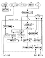
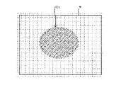
以上の構成からなる本装置の制御動作を図8のフローチャートに従って説明する。ステップS1にて、送受波器1より、全方位に超音波が送波され、そのエコーは形成した受波ビームにより受波され、画面記憶メモリ7に記憶されると共に、図9のごとくモニター9にエコーが魚群X1、X2として表示される。中心に位置するのは自船位置Jを示す。
【0024】
ステップS2ではそのモニター画面を見て、標的とする魚群X1を定め、モニター上でその魚群X1の中心部Oをカーソルで指示すると、ステップS3において、その魚群X1を中心とするメインエリアW1とそれと同サイズのサブエリアwが設定される。但しモニターにはメインエリアW1のみが表示される。そのメインエリアW1のサイズは自船Jから魚群X1までの距離に比例して変化する。
【0025】
次の送波タイミングになれば、ステップS4からステップS5に進み、受波ビームが魚群X1に向かうように、チルト角が設定される。図10において、自船がJに示した位置のとき、受波ビームR1はチルト角T1(もしくはT1を挟む範囲で垂直スキャン)に設定され、自船がJ'に示した位置まで進んだときは、受波ビームR2はチルト角T2にされる。図10中のZは、図9において指定した魚群中心Oを確認するために表示されるマークであり、後述するように魚群X1の移動が検出されると魚マークに変わる。
【0026】
ステップS6では、再度、送波が行われ、それによるエコーが受波され記憶、表示される。このときの表示を図11に示す。ここでは自船Jより前方のみを拡大して示した。メインエリアW1に対して魚群X1が右上に移動しているのは、魚群X1の移動もしくは自船Jの動揺あるいは双方の要因による。次のステップS7ではサブエリアw内で存在する魚群が認識される。
【0027】
ステップS8では、認識した魚群が複数個ある場合、その中から標的とした魚群が選出される。
【0028】
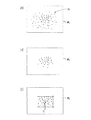
次のステップS9では、標的とした魚群X1の中心が上述したように重心の検出により行われる。図12は魚群中心の別の検出方法を示している。図12の(A)は、メインエリアW1にある魚群X1を示し、この魚群X1の中心を求めるに際し、魚群X1の各画素における平均レベルを演算し、(B)に示すように、その平均レベルを上回るドットのデータのみを抽出し、そして、(C)に示すように、それらのデータを囲む最小の四辺形をあてがい、その四辺形の中心Oを魚群X1の中心としている。
【0029】
次のステップS10では図13に示すように、魚群中心Oが中央に位置するようにサブエリアwを移動させ、かつ、そのサブエリアwのサイズは、自船Jから魚群中心Oまで距離に比例して変化させる。
【0030】
ステップS11では、魚群X1の規模を数値化するために魚量値Qが演算され、後で示すようにモニターに表示される。その魚量値Qの求め方を図14を用いて説明する。サブエリアw内にある総ドット数をSとし、各ドットのレベルを16段階(L1〜L16)とし、レベルLxのドット数をnxとして、
魚量値Q=(n1L1+n2L2+…+n16L16)/S
を求める。
【0031】
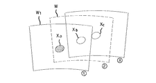
ステップS12では魚群中心OがメインエリアW1外かが判定される。図15において、Xaの位置にあった魚群がXbの位置に移動していたとき(このときサブエリアwは位置▲1▼から位置▲2▼に移動している)、魚群はメインエリアW1内にあるのでステップS12からステップS15に進む。
【0032】
一方、魚群がXcの位置まで移動したとき(サブエリアwは位置▲3▼に移動)、メインエリアW1外となるのでステップS12からステップS13に進み、位置▲1▼のメインエリアW1は、位置▲3▼へ移動し、そのサイズもサブエリアwと同一にされるため、再び、メインエリアとサブエリアが合致する。このようにサブエリアwは魚群中心Oの移動に追随して移動するがメインエリアW1は魚群中心Oがエリア外となったときに初めて移動する。
【0033】
ステップS14では、前記の2点間の移動から魚群X1の軌跡が表示される。図16は、魚群X1の軌跡Lを示しており、L1、L2、…が2点間の移動を示す。又、魚群X1の移動方向は魚のマークPの向きでも表示される。図2の軌跡と表示してわかるように、船体の動揺等に伴う魚群X1の不可解な移動軌跡が表示されていない。
【0034】
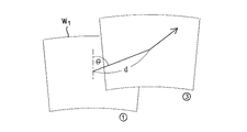
ステップS15では、速度および方位の表示タイミングになったかが判定され、例えば、30秒、45秒あるいは60秒が経過する毎にステップS16に進み図17に示すように、メインエリアの2点間の移動距離dとその方位θから移動速度Vおよび移動方位Dがモニター9に表示される。
【0035】
本発明では魚群の中心検出に、最高レベル(1点)で捕えるのではなく、図7で示したように、領域で捕えるため、中心検出の精度が高く、それ故、図3、図4で示したように、標的としていた魚群を見失うといったことは少ない。仮に見失うことがあっても、図18に示したように、標的をX2からX1に戻したとき、魚群X1のこれまでの軌跡Lがそのまま表示されるので使い勝手がよい。
【0036】
【発明の効果】
以上説明したように、本発明は、検出結果をそのまま表示するのではなく、例えば魚群が一定距離を移動する毎に、画面に出力するようにしたので、船体の動揺等に起因する短時間の変化データは排除され、魚群の移動軌跡や移動方位を正確に表示できる。
【図面の簡単な説明】
【図1】 スキャニングソナーにおける受波ビームの形成を示した図
【図2】 従来の装置で表示される魚群の移動軌跡を示した図
【図3】 従来の装置で標的としていた魚群X1を見失ったときの状況を示した図
【図4】 別の魚群X2を標的とした様子を示した図
【図5】 標的を再指定するときの様子を示した図
【図6】 自船から魚群までの距離に応じてメインエリアWのサイズが変わる様子を示した図
【図7】 魚群中心の検出を示した図
【図8】 本発明の1実施形態を示した制御ブロック図
【図9】 図8の装置の制御動作を示したフローチャート
【図10】 本発明の装置で魚群中心を指示した様子を示した図
【図11】 チルト角の設定を示した図
【図12】 メインエリア内で魚群が移動した様子を示した図
【図13】 魚群の移動に追随してサブエリアが移動する様子を示した図
【図14】 魚量値の演算の説明に用いた図
【図15】 メインエリアW1から魚群が移動した時の様子を示した図
【図16】 メインエリアの移動から軌跡や移動方位を求める様子を示した図
【図17】 本発明の装置で表示された軌跡を示した図
【図18】 本発明の装置で元の標的に変更したときの様子を示した図
【符号の説明】
1 送受波器
3 垂直ビーム合成回路
4 水平ビーム合成回路
7 画面記憶メモリ
9 モニター
10 CPU
11 魚群認識部
12 魚群選択部
13 標的中心検出部
14 距離演算部
15 サブエリアサイズ・位置設定部
16 チルト角演算部
17 メインエリア外判定部
18 メインエリア設定部
19 標的速度演算部
20 速度補正部
21 魚量値演算部
R 受波ビーム
X 魚群
J 自船
W メインエリア
w サブエリア[0001]
BACKGROUND OF THE INVENTION
The present invention relates to a scanning sonar, an automatic fish tracking scanning sonar particularly have a function of target can be automatically tracked.
[0002]
[Prior art]
In fishing rods, it is important not only to know the position of the school of fish, but also to know in what direction and at what speed the fish school is moving in order to set up the net. It is necessary to have a device with the function to do this. For example, there is "Target-scanning type scanning sonar" of No. 7-19020, which is outlined below.
[0003]
First, by looking at the detection image displayed on the monitor, an event mark is attached with the target fish center as the target with the highest display density. As a result, a tracking detection area centered on the event mark is set, and beam scanning is performed so that the beam center faces the event mark. With respect to the detection signal obtained by this beam scan, a portion having the highest level in the area is selected, an event mark is replaced at that portion, and a tracking detection area is newly set for the event mark. . The target center is automatically tracked by repeating the beam scanning operation toward the newly determined event mark.
[0004]
As shown in FIG. 1, the scanning sonar transmits ultrasonic waves in all directions toward the seabed from a
[0005]
The scanning sonar of this publication does not describe the target trajectory display or moving speed, but it is possible to know the trajectory display, moving direction and moving speed by plotting the target position at fixed time intervals. Such a system has already been put into practical use. FIG. 2 shows a trajectory display example of such a system. The center of the screen is the ship position, and X is the image of the school of fish set as the target. L is the trajectory of the fish school X. The direction of the fish mark P drawn at the center of the fish school X indicates the current movement direction of the fish school X. In the lower right of the screen, the moving speed and moving direction of the fish school X are shown. Looking at this trajectory L, the school of fish X is moving as if it were wandering, but it is not actually moving like that, and the cause of this display is due to the ship's hull shaking. It is. As can be seen from the locus L, the direction of the mark P changes every moment.
[0006]
[Problems to be solved by the invention]
Because of such a confusing display, the true movement trajectory and movement direction of the fish school X cannot be known. Although it is possible to detect the shaking of the hull and correct the detected echo signal to eliminate the shaking, it is technically difficult to detect the shaking in three directions in the hull and correct the echo signal. In addition, since the echo slightly fluctuates due to a slight change in the beam angle, even if complete correction can be performed, it is not possible to completely eliminate the influence caused by the fluctuation.
[0007]
Further, in the above publication, when the center of the fish school X is detected, it is set as the maximum signal level. However, when the detection signal is abnormally strong and the signal is saturated, the center of the fish school X is selected. It becomes impossible to detect accurately, so that accurate target tracking cannot be performed. For example, in FIG. 3, J indicates the own ship, and W indicates the above-described area. If the fish group X 1 tracked in the area W is lost, the target object suddenly shifts to the fish group X 2 , and FIG. As shown in FIG. 2 , the fish group X 2 is set as a tracking target. In that case, as shown in FIG. 5, it is necessary to re-specify the target from X 2 to X 1 , and in that case, the trajectory L up to that point is cleared, and it is necessary to start over from the beginning.
[0008]
The present invention has been made to solve the above-described problems, and provides a scanning sonar that can accurately know the moving speed, moving direction, and moving trajectory of a target and has high tracking ability of the target. For the purpose.
[0009]
[Means for Solving the Problems]
In the conventional system described above, a misleading display is output in order to display the detection result as a locus as it is. The hull oscillation period is generally a few seconds or so. Therefore, every time a predetermined time elapses or every time a school of fish moves a predetermined distance, if it is output on the screen, that is, if a dead zone that does not output detection data is provided, it will cause fluctuations that occur within a short time. The associated false detection data can be eliminated.
[0010]
If a fixed time is set as a dead zone, the fish position is displayed almost accurately each time the fish moves at a low speed. However, if the hull is shaken during data detection, the fish The direction of movement is not determined and the exact direction of movement is not displayed. Therefore, in the present invention, as shown in
[0011]
The target moving speed is calculated by the moving distance and the time required for the movement. However, the shorter the distance and the time, that is, the instantaneous speed changes greatly and a stable result cannot be obtained. Therefore, using a speed obtained by averaging the instantaneous speed over a predetermined time provides a stable and easy-to-see result. Here, the time required for the movement is ensured to be equal to or longer than a predetermined time , thereby providing an averaging effect . The same means was used for the moving direction.
[0012]
As means for knowing that the school of fish has moved a certain distance in a straight line from the movement source point, in
[0013]
As shown in FIG. 6, when the fish school X moves away from its own ship J without changing its size, the beam diameter of the received beam R also increases. Is displayed as the distance from own ship J increases. Therefore, it is necessary to increase the size of the area W provided as means for knowing that it has moved a certain distance, as shown in
[0014]
Since the area W 1 shown in FIG. 15 is for knowing the moving distance of the fish school Xa, the area does not move even if the fish school Xa moves. Therefore, in order to track the fish shown in Xb in the area W within 1 it is provided with a sub-area w for tracking moving to follow the movement. In order to distinguish this, the previous area W 1 is referred to as a main area.
[0015]
The fish echoes in the main area W 1 are binarized at the obtained level. When the binarized data chunk is expanded (filling out the missing part) and there are a plurality of target candidates, that is, data chunks, the data chunk is narrowed down to one by feature extraction. After narrowing the data chunk to one, the center of gravity of the data chunk is obtained and set as the center of the target.
[0016]
Here, the target echo selection and the means for preventing misidentification tracking will be described.
(Target echo selection)
The following parameters are set to identify the fish echo.
Area: A, distance: L, strength: S, aspect ratio: R
A weighted sum is defined as a feature value.
Feature P = αA + βL + ηS + γR
For example, set the weight as follows,
In the
In
A judgment formula suitable for the target is selected, and a feature amount P is obtained.
Select the highest feature value.
(Preventing misidentification tracking)
In some cases, the target echo may be interrupted without being received. In this case, a filter is provided to prevent misidentification tracking of other targets.
1. If the speed limit filter target is lost and other targets are misidentified and tracked, the instantaneous speed moved will be large. By providing a limit speed, it is possible to prevent misidentification tracking.
2. In the case of an acceleration limiting filter target, it is usually moving at a constant speed, and the change in speed, that is, the acceleration is usually below a certain level. Therefore, false tracking can be prevented by providing a limit acceleration.
[0017]
In the present invention, the fish quantity value is obtained in order to quantify the scale of the school of fish, and the calculation method will be described in detail later using mathematical expressions.
[0018]
DETAILED DESCRIPTION OF THE INVENTION
FIG. 7 is a control block diagram showing an embodiment of the scanning sonar of the present invention.
[0019]
[0020]
[0021]
[0022]
[0023]
The control operation of this apparatus having the above configuration will be described with reference to the flowchart of FIG. In step S1, ultrasonic waves are transmitted from the transmitter /
[0024]
Looking at the monitor screen in step S2, determines the fish X 1 targeting, and instructs the center O of the fish X 1 on the monitor with the cursor, in step S3, the main area around the fish X 1 W 1 and a sub-area w having the same size are set. However, the monitor only the main area W 1 is displayed. The size of the main area W 1 changes in proportion to the distance from the own ship J to the fish school X 1 .
[0025]
If the next transmission timing, the process proceeds from step S4 to step S5, reception beam is to be directed to fish X 1, the tilt angle is set. In FIG. 10, when the ship is at the position indicated by J, the received beam R 1 is set to the tilt angle T 1 (or vertical scan within the range of T 1 ), and the ship is to the position indicated by J ′. When advanced, the received beam R 2 is at a tilt angle T 2 . Z in FIG. 10 is a mark displayed for confirming the fish center O designated in FIG. 9, and changes to a fish mark when movement of the fish school X 1 is detected as will be described later.
[0026]
In step S6, the wave is transmitted again, and an echo is received, stored and displayed. The display at this time is shown in FIG. Here, only the front side of own ship J is shown enlarged. The movement of the fish school X 1 to the upper right with respect to the main area W 1 is due to the movement of the fish school X 1 , the swaying of the own ship J, or both factors. In the next step S7, the school of fish present in the subarea w is recognized.
[0027]
In step S8, when there are a plurality of recognized fish schools, the target fish school is selected from them.
[0028]
In the next step S9, the center of the target fish school X1 is detected by detecting the center of gravity as described above. FIG. 12 shows another method for detecting the center of a school of fish. (A) of FIG. 12 shows a fish X1 in the main area W1, upon obtaining the center of the fish X1, calculates the average level of definitive to each pixel of the fish X1, (B), the average Only dot data exceeding the level is extracted, and as shown in (C), the smallest quadrangle surrounding those data is assigned, and the center O of the quadrangle is set as the center of the fish school X1.
[0029]
In the next step S10, as shown in FIG. 13, the sub-area w is moved so that the fish center O is located in the center, and the size of the sub-area w is proportional to the distance from the own ship J to the fish center O. To change.
[0030]
In step S11, Sakanaryou value Q is calculated in order to quantify the size of fish X 1, are displayed on the monitor as shown below. A method for obtaining the fish quantity value Q will be described with reference to FIG. The total number of dots in the sub-area w is S, the level of each dot is 16 levels (L 1 to L 16 ), the number of dots of the level Lx is nx,
Fish quantity value Q = (n 1 L 1 + n 2 L 2 +... + N 16 L 16 ) / S
Ask for.
[0031]
Step S12, fish center O is the main area W 1 or the external is determined. In FIG. 15, when the fish school that was at the position of Xa has moved to the position of Xb (at this time, the sub-area w has moved from position (1) to position (2)), the school of fish is the main area W 1. Since it is within, the process proceeds from step S12 to step S15.
[0032]
On the other hand, fish (moved in ▼ subarea w position ▲ 3) is when moved to the position of Xc, the process proceeds from step S12 since the main area W 1 outside step S13, the position ▲ 1 ▼ main area W 1 of , Move to position {circle around (3)}, and its size is also made the same as that of the sub area w, so that the main area and the sub area again coincide. In this way, the sub area w moves following the movement of the fish center O, but the main area W 1 moves only when the fish center O is out of the area.
[0033]
In step S14, the locus of fish X 1 is displayed from the movement between two points of said. FIG. 16 shows the trajectory L of the fish school X 1 , and L 1 , L 2 ,... Indicate movement between two points. Further, the moving direction of the fish school X 1 is also displayed in the direction of the fish mark P. As can be seen by displaying the trajectory in FIG. 2, the mysterious movement trajectory of the fish school X 1 due to the fluctuation of the hull is not displayed.
[0034]
In step S15, it is determined whether the display timing of speed and direction has come. For example, each time 30 seconds, 45 seconds, or 60 seconds have passed, the process proceeds to step S16, and as shown in FIG. The moving speed V and the moving direction D are displayed on the
[0035]
In the present invention, the center detection of the school of fish is not caught at the highest level (one point), but is caught in the region as shown in FIG. 7, so the center detection accuracy is high. Therefore, in FIG. 3 and FIG. As shown, it is rare to lose sight of the target school of fish. Even if it is missed, as shown in FIG. 18, when the target is returned from X 2 to X 1 , the trajectory L of the fish school X 1 so far is displayed as it is, which is convenient.
[0036]
【The invention's effect】
As described above, the present invention does not display the detection result as it is, but outputs it to the screen every time the school of fish moves a certain distance, for example. Change data is eliminated, and the movement trajectory and direction of the school of fish can be accurately displayed.
[Brief description of the drawings]
FIG. 1 is a diagram showing the formation of a received beam in a scanning sonar. FIG. 2 is a diagram showing a movement trajectory of a school of fish displayed by a conventional device. FIG. 3 is a diagram showing a fish school X 1 targeted by a conventional device. Figure showing the situation when it was lost [Figure 4] Figure showing the situation where another fish school X 2 was targeted [Figure 5] Figure showing the situation when re-designating the target [Figure 6] From own ship FIG. 7 is a diagram showing how the size of the main area W changes according to the distance to the fish school. FIG. 7 is a diagram showing detection of the fish center. FIG. 8 is a control block diagram showing one embodiment of the present invention. FIG. 10 is a flowchart showing the control operation of the apparatus of FIG. 8. FIG. 10 is a diagram showing how the fish center is indicated by the apparatus of the present invention. FIG. 11 is a diagram showing the setting of the tilt angle. Fig. 13 shows the movement of a school of fish [Fig. 13] Following the movement of a school of fish Figure 16 shows the sub-area showing a state when a fish from Figure [15] main area W 1 used in the description of the operation of FIG. 14 is a fish quantity value showing a state in which movement is moved Te FIG. 17 is a diagram showing how the trajectory and the moving direction are obtained from the movement of the main area. FIG. 17 is a diagram showing the trajectory displayed by the apparatus of the present invention. Figure showing the situation [Explanation of symbols]
DESCRIPTION OF
DESCRIPTION OF SYMBOLS 11 Fish
Claims (7)
検出した標的中心が中央に位置するように所定サイズのメインエリアを設定し、その後に検出される標的中心が前記メインエリア内に存在する限り、前記メインエリアの位置は固定され、前記標的中心がメインエリアから外れたと判定されたとき、改めて、前記標的中心が中央に位置するように前記メインエリアを移動し、このとき、標的中心が、メインエリアの中央からメインエリア外へ移動した時の2点間の移動データから標的の移動軌跡を表示することを特徴とする自動魚群追尾スキャニングソナー。In the scanning sonar that automatically detects the target by detecting the center of the target from the level intensity of the echo signal from underwater and determining the transmission beam at the target center,
A main area of a predetermined size is set so that the detected target center is located in the center, and the position of the main area is fixed as long as the target center detected thereafter is present in the main area. When it is determined that the target center is out of the main area, the main area is moved again so that the target center is located at the center. At this time, the target center moves from the center of the main area to the outside of the main area. automatic fish tracking scanning sonar, characterized by displaying the moving trajectories of the target from the moving data between the points.
魚量値=(n1L1+n2L2+…+nxLx)/Sを求める請求項1〜5のいずれかに記載の自動魚群追尾スキャニングソナー。When determining the target center, a sub area for target tracking is set separately from the main area, and in order to quantify the scale of the school of fish, S is the total number of dots detected in the sub area, Are classified into L 1 to Lx, and the number of dots of level Lx is nx,
The automatic fish school tracking scanning sonar according to claim 1, wherein the fish quantity value = (n 1 L 1 + n 2 L 2 +... + NxLx) / S is obtained.
検出した魚群中心が中央に位置するように所定サイズのメインエリアを設定し、その後に検出される魚群中心が前記メインエリア内に存在する限り、前記メインエリアの位置は固定され、前記魚群中心がメインエリアから外れたと判定されたとき、改めて、前記魚群中心が中央に位置するように前記メインエリアを移動し、このとき、魚群中心が、メインエリアの中央からメインエリア外へ移動した時の2点間の移動データから魚群の移動軌跡を表示し、
上記魚群中心を求めるに際し、上記メインエリア内のデータをユーザーが選択できるレベルで2値化し、'1'のデータ群を魚群エコーに対応する塊になるよう膨張処理を施し、魚群エコーが複数存在した場合は、魚群エコーの面積、前回の魚群中心からの距離、強度、縦横比を算出しそれぞれユーザーが設定できる重みを掛けたものの和を特徴量とし、最大のものを抽出する、という特徴抽出により一つを選択し、選ばれた魚群エコーつまり'1'のデータ群の重心を魚群中心とすることを特徴とする自動魚群追尾スキャニングソナー。In a scanning sonar that automatically tracks the school of fish by detecting the center of the school of fish from the level intensity of the echo signal from underwater and determining the transmission beam at the center of the school of fish,
A main area of a predetermined size is set so that the detected fish center is located in the center, and as long as the subsequently detected fish center exists in the main area, the position of the main area is fixed, and the fish center is When it is determined that the fish center is out of the main area, the main area is moved again so that the fish center is located at the center. At this time, the fish center moves from the center of the main area to the outside of the main area. to display the fish school of movement trajectories from moving data between points,
When determining the fish center, the data in the main area is binarized at a level that can be selected by the user, and the data group of '1' is expanded to a lump corresponding to the fish echo, and there are multiple fish echoes. In this case, the feature extraction is to calculate the area of the fish echo, the distance from the previous fish center, the intensity, and the aspect ratio, and add the weights that can be set by the user as feature amounts, and extract the maximum one. An automatic fish tracking scanning sonar that selects one according to, and sets the center of the selected fish echo, that is, the data group of '1' as the fish center.
Priority Applications (1)
| Application Number | Priority Date | Filing Date | Title |
|---|---|---|---|
| JP12308298A JP4106124B2 (en) | 1998-05-06 | 1998-05-06 | Automatic fish tracking tracking sonar |
Applications Claiming Priority (1)
| Application Number | Priority Date | Filing Date | Title |
|---|---|---|---|
| JP12308298A JP4106124B2 (en) | 1998-05-06 | 1998-05-06 | Automatic fish tracking tracking sonar |
Publications (2)
| Publication Number | Publication Date |
|---|---|
| JPH11316277A JPH11316277A (en) | 1999-11-16 |
| JP4106124B2 true JP4106124B2 (en) | 2008-06-25 |
Family
ID=14851761
Family Applications (1)
| Application Number | Title | Priority Date | Filing Date |
|---|---|---|---|
| JP12308298A Expired - Fee Related JP4106124B2 (en) | 1998-05-06 | 1998-05-06 | Automatic fish tracking tracking sonar |
Country Status (1)
| Country | Link |
|---|---|
| JP (1) | JP4106124B2 (en) |
Families Citing this family (15)
| Publication number | Priority date | Publication date | Assignee | Title |
|---|---|---|---|---|
| JP2003185746A (en) * | 2001-12-21 | 2003-07-03 | Nichimo Co Ltd | Trawl operation method, and monitor for fish moving- behavior used therefor |
| JP5073160B2 (en) * | 2004-10-01 | 2012-11-14 | 古野電気株式会社 | Underwater detection device capable of calculating fish school information, fish school volume and backscattering intensity of a single fish, and methods thereof |
| JP5082031B2 (en) * | 2004-10-01 | 2012-11-28 | 国立大学法人北海道大学 | Underwater detection apparatus and method capable of calculating fish quantity information of a school of fish |
| JP2007327855A (en) * | 2006-06-08 | 2007-12-20 | Japan Radio Co Ltd | Automatic tracking scanning sonar |
| JP5096205B2 (en) * | 2007-03-26 | 2012-12-12 | 日本無線株式会社 | Automatic tracking scanning sonar |
| JP5547889B2 (en) * | 2008-12-18 | 2014-07-16 | 日本無線株式会社 | Scanning sonar device and tracking method |
| JP5322619B2 (en) * | 2008-12-18 | 2013-10-23 | 日本無線株式会社 | Scanning sonar device |
| JP2010145224A (en) * | 2008-12-18 | 2010-07-01 | Japan Radio Co Ltd | Scanning sonar device |
| JP5303284B2 (en) * | 2009-01-14 | 2013-10-02 | 日本無線株式会社 | Target image tracking device and target image tracking method |
| JP5257783B2 (en) * | 2009-05-11 | 2013-08-07 | 古野電気株式会社 | Underwater detection device and underwater detection image display method |
| JP2014077701A (en) * | 2012-10-10 | 2014-05-01 | Furuno Electric Co Ltd | Fish finding device, signal processing device, fish finder, fish finding method and program |
| US10481259B2 (en) | 2013-09-13 | 2019-11-19 | Navico Holding As | Tracking targets on a sonar image |
| KR101772507B1 (en) * | 2016-03-15 | 2017-09-12 | 부경대학교 산학협력단 | System for indicating and controlling a purse seine net shooting tract |
| JP2021123318A (en) * | 2020-02-10 | 2021-08-30 | 三井E&S造船株式会社 | Automatic maneuvering system |
| CN114019519B (en) * | 2022-01-05 | 2022-03-29 | 视丰达科技(深圳)有限公司 | Track recording method and equipment of leveling ranging fish finder |
-
1998
- 1998-05-06 JP JP12308298A patent/JP4106124B2/en not_active Expired - Fee Related
Also Published As
| Publication number | Publication date |
|---|---|
| JPH11316277A (en) | 1999-11-16 |
Similar Documents
| Publication | Publication Date | Title |
|---|---|---|
| JP4106124B2 (en) | Automatic fish tracking tracking sonar | |
| JP4033704B2 (en) | Auto-tracking scanning sonar | |
| JP4795675B2 (en) | Medical ultrasound system | |
| US20130343151A1 (en) | Underwater detection device | |
| US7916069B2 (en) | Radar device | |
| US7327636B2 (en) | Underwater sounding apparatus and method capable of calculating fish school information, volume of fish school and backscattering strength of single fish | |
| JP2006052987A (en) | Forward detection sonar and underwater imaging display apparatus | |
| US10585184B2 (en) | Tracking processor and method of tracking processing | |
| JP5767002B2 (en) | Ultrasonic transmission / reception device and fish quantity detection method | |
| JP2021100474A (en) | Ultrasonic diagnostic device, control method of ultrasonic diagnostic device and control program of ultrasonic diagnostic device | |
| US6980484B2 (en) | Fish finding device and method for detecting and distinguishing marine life from a sonar reflected marker | |
| JP2004347319A (en) | Ultrasonic transmitting and receiving apparatus | |
| EP1126288A2 (en) | Ultrasound imaging system for performing receiving focusing at points corresponding to display pixels and method thereof | |
| US20020080058A1 (en) | Detecting apparatus | |
| JP7163555B2 (en) | Underwater information visualization device | |
| JP7219640B2 (en) | Underwater detection device and underwater detection method | |
| JP3429362B2 (en) | Fish finder | |
| JP2010145224A (en) | Scanning sonar device | |
| KR101740538B1 (en) | Method for Correction Shaking Image of Side-Scan Sonar | |
| CN207601853U (en) | Radiation image corrects system | |
| JP3822654B2 (en) | Fish finder | |
| JP2019132717A (en) | Velocity computation device, velocity computation method, and program | |
| JP2023089649A (en) | Orientation radar device and beam control method | |
| JP2012108049A (en) | Signal processor, radar device, signal processing method and signal specific program | |
| JPH04138273U (en) | Ultrasonic Doppler current meter |
Legal Events
| Date | Code | Title | Description |
|---|---|---|---|
| A521 | Written amendment |
Free format text: JAPANESE INTERMEDIATE CODE: A523 Effective date: 20050426 |
|
| A621 | Written request for application examination |
Free format text: JAPANESE INTERMEDIATE CODE: A621 Effective date: 20050426 |
|
| A977 | Report on retrieval |
Free format text: JAPANESE INTERMEDIATE CODE: A971007 Effective date: 20070206 |
|
| A131 | Notification of reasons for refusal |
Free format text: JAPANESE INTERMEDIATE CODE: A131 Effective date: 20070213 |
|
| A521 | Written amendment |
Free format text: JAPANESE INTERMEDIATE CODE: A523 Effective date: 20070413 |
|
| A131 | Notification of reasons for refusal |
Free format text: JAPANESE INTERMEDIATE CODE: A131 Effective date: 20071023 |
|
| A521 | Written amendment |
Free format text: JAPANESE INTERMEDIATE CODE: A523 Effective date: 20071126 |
|
| TRDD | Decision of grant or rejection written | ||
| A01 | Written decision to grant a patent or to grant a registration (utility model) |
Free format text: JAPANESE INTERMEDIATE CODE: A01 Effective date: 20080325 |
|
| A61 | First payment of annual fees (during grant procedure) |
Free format text: JAPANESE INTERMEDIATE CODE: A61 Effective date: 20080331 |
|
| R150 | Certificate of patent or registration of utility model |
Free format text: JAPANESE INTERMEDIATE CODE: R150 |
|
| FPAY | Renewal fee payment (event date is renewal date of database) |
Free format text: PAYMENT UNTIL: 20110404 Year of fee payment: 3 |
|
| FPAY | Renewal fee payment (event date is renewal date of database) |
Free format text: PAYMENT UNTIL: 20120404 Year of fee payment: 4 |
|
| FPAY | Renewal fee payment (event date is renewal date of database) |
Free format text: PAYMENT UNTIL: 20130404 Year of fee payment: 5 |
|
| FPAY | Renewal fee payment (event date is renewal date of database) |
Free format text: PAYMENT UNTIL: 20140404 Year of fee payment: 6 |
|
| R250 | Receipt of annual fees |
Free format text: JAPANESE INTERMEDIATE CODE: R250 |
|
| LAPS | Cancellation because of no payment of annual fees |