JP4105153B2 - Electric vacuum cleaner - Google Patents
Electric vacuum cleaner Download PDFInfo
- Publication number
- JP4105153B2 JP4105153B2 JP2004371795A JP2004371795A JP4105153B2 JP 4105153 B2 JP4105153 B2 JP 4105153B2 JP 2004371795 A JP2004371795 A JP 2004371795A JP 2004371795 A JP2004371795 A JP 2004371795A JP 4105153 B2 JP4105153 B2 JP 4105153B2
- Authority
- JP
- Japan
- Prior art keywords
- air
- vacuum cleaner
- main body
- motor
- exhaust filter
- Prior art date
- Legal status (The legal status is an assumption and is not a legal conclusion. Google has not performed a legal analysis and makes no representation as to the accuracy of the status listed.)
- Expired - Fee Related
Links
Images


Classifications
-
- A—HUMAN NECESSITIES
- A47—FURNITURE; DOMESTIC ARTICLES OR APPLIANCES; COFFEE MILLS; SPICE MILLS; SUCTION CLEANERS IN GENERAL
- A47L—DOMESTIC WASHING OR CLEANING; SUCTION CLEANERS IN GENERAL
- A47L9/00—Details or accessories of suction cleaners, e.g. mechanical means for controlling the suction or for effecting pulsating action; Storing devices specially adapted to suction cleaners or parts thereof; Carrying-vehicles specially adapted for suction cleaners
- A47L9/0081—Means for exhaust-air diffusion; Means for sound or vibration damping
-
- A—HUMAN NECESSITIES
- A47—FURNITURE; DOMESTIC ARTICLES OR APPLIANCES; COFFEE MILLS; SPICE MILLS; SUCTION CLEANERS IN GENERAL
- A47L—DOMESTIC WASHING OR CLEANING; SUCTION CLEANERS IN GENERAL
- A47L9/00—Details or accessories of suction cleaners, e.g. mechanical means for controlling the suction or for effecting pulsating action; Storing devices specially adapted to suction cleaners or parts thereof; Carrying-vehicles specially adapted for suction cleaners
- A47L9/10—Filters; Dust separators; Dust removal; Automatic exchange of filters
- A47L9/12—Dry filters
- A47L9/122—Dry filters flat
-
- A—HUMAN NECESSITIES
- A47—FURNITURE; DOMESTIC ARTICLES OR APPLIANCES; COFFEE MILLS; SPICE MILLS; SUCTION CLEANERS IN GENERAL
- A47L—DOMESTIC WASHING OR CLEANING; SUCTION CLEANERS IN GENERAL
- A47L9/00—Details or accessories of suction cleaners, e.g. mechanical means for controlling the suction or for effecting pulsating action; Storing devices specially adapted to suction cleaners or parts thereof; Carrying-vehicles specially adapted for suction cleaners
- A47L9/22—Mountings for motor fan assemblies
-
- A—HUMAN NECESSITIES
- A47—FURNITURE; DOMESTIC ARTICLES OR APPLIANCES; COFFEE MILLS; SPICE MILLS; SUCTION CLEANERS IN GENERAL
- A47L—DOMESTIC WASHING OR CLEANING; SUCTION CLEANERS IN GENERAL
- A47L9/00—Details or accessories of suction cleaners, e.g. mechanical means for controlling the suction or for effecting pulsating action; Storing devices specially adapted to suction cleaners or parts thereof; Carrying-vehicles specially adapted for suction cleaners
- A47L9/26—Incorporation of winding devices for electric cables
Description
本発明は、電気掃除機に関し、より詳しくは、電気掃除機の内部の空気を排出するための排気孔を通過した空気の流れを分岐させることにより、電気掃除機内に配置されている放熱部品の冷却及び騷音を低減させることができる電気掃除機に関する。 The present invention relates to a vacuum cleaner. More specifically, the present invention relates to a heat radiating component disposed in a vacuum cleaner by branching the flow of air that has passed through an exhaust hole for exhausting air inside the vacuum cleaner. The present invention relates to a vacuum cleaner that can reduce cooling and noise.
通常、電気掃除機(vacuum cleaner)は、モータ組立体により発生する強い吸引力を利用してゴミ、チリ、ほこりなどの異物を除去する。このような電気掃除機は、例えば電源コードのような放熱部品を冷却する冷却システムを含むことが好ましい。 Generally, a vacuum cleaner removes foreign matters such as dust, dust, and dust by using a strong suction force generated by a motor assembly. Such a vacuum cleaner preferably includes a cooling system for cooling a heat dissipating component such as a power cord.
このような従来の電気掃除機のうちの1つとして、米国特許公報U.S.P.No 6,611,989号に記載されている「冷却特徴を有する電気掃除機」があり、これを図1に示す。図示のように、従来の電気掃除機は、異物を含む空気を吸入するための吸入ヘッド10と、この吸入ヘッド10と連結されているケース20とを含む。
As one of such conventional vacuum cleaners, there is a “vacuum cleaner having a cooling feature” described in US Pat. No. 6,611,989. As shown in FIG. As shown in the figure, the conventional vacuum cleaner includes a
ケース20は、異物を含む空気から粗大な異物を捕獲するための集塵袋24を有する集塵室22、吸引力を発生させるためのファンモータ組立体30を有する機器室(appliance chamber)26及び電源コード42を収納するためのコード室40を含み、これらの室22、26、40は隔壁44、46、48により分離されている。
The
集塵室22は、ケース20の前方に位置し、機器室26及びコード室40は集塵室22の後ろのケース20の後方に配置され、隔壁48により分離されている。
The
ファンモータ組立体30は、モータ筐体32、モータ筐体32の周辺に配置される吸音スリーブ34及びモータ筐体32からの空気を機器室26に排出させるための複数の排出口36を含む。
The
集塵室22と機器室26との間に位置する隔壁44には、集塵袋24からの空気をファンモータ組立体30に通過させる空気吸引口45が備えられ、集塵室22とコード室40との間に設けられる隔壁46には、これらの間の空気移動のための空気孔47が備えられる。
The
また、ケース20は、ファンモータ組立体30からの空気から微細な異物をフィルタリングするための排気フィルタ49と、排気フィルタ49を通過した空気を外部に排出させるための複数の排気孔50とを含む。
The
以下、このような従来の電気掃除機の動作について説明する。 Hereinafter, the operation of such a conventional vacuum cleaner will be described.
電源コード42をコード通過孔(図示せず)を通してプラグ(図示せず)に差し込むことによって、電気掃除機が駆動すれば、異物を含む空気はファンモータ組立体30により吸入ヘッド10を通して集塵袋24に吸入され、粗大な異物が集塵袋24に堆積される。その後、集塵袋24を通過した空気の一部は、空気吸引口45を通してファンモータ組立体30に吸引され、排出口36を通して機器室26に排出される。空気が排出口36を通して排出されるとき、騷音が発生するが、この騷音は吸音スリーブ34により減少される。従って、排出された空気は、排気フィルタ49を通して浄化され、最終的に排気孔50を通して電気掃除機の外部に排出される。残った空気は、集塵袋24を通過して空気孔47を通してコード室40に流れ込み、電源コード42を冷却させる。
When the vacuum cleaner is driven by inserting the
このような構成において、電源コードを冷却させるための空気は、集塵室から空気孔を通して直接コード室に流れ込み、コード通過孔を通して外部に排出される。すなわち、排気フィルタによりフィルタリングされずに排出されるため、非衛生的な異物が外部に排出され、不快な臭いが発生する。 In such a configuration, air for cooling the power cord flows directly from the dust collection chamber into the cord chamber through the air hole and is discharged to the outside through the cord passage hole. That is, since it is discharged without being filtered by the exhaust filter, unsanitary foreign matter is discharged to the outside and an unpleasant odor is generated.
また、電源コード以外の放熱部品に対しては、冷却させることができないという問題があった。 In addition, there is a problem that heat dissipation parts other than the power cord cannot be cooled.
したがって、本発明はこのような従来の問題点を解決するためになされたもので、その目的は、排気フィルタを通過した空気の流れを分岐させて様々な放熱部品を冷却させることができるほか、騷音を低減させることもできる電気掃除機を提供することである。 Therefore, the present invention has been made to solve such a conventional problem, and its purpose is to branch the flow of air that has passed through the exhaust filter to cool various heat dissipation components, It is providing the vacuum cleaner which can also reduce a noise.
上記目的を達成するために本発明の一様態による電気掃除機は、本体と、前記本体内部に設置されて吸引力を発生させるモータを有するモータ組立体と、前記本体内の後方部に備えられて前記モータ組立体を通過した空気から微細な異物をフィルタリングするための排気フィルタと、前記排気フィルタを通過した空気の一部を本体内部にガイドするためのガイド部材とを含むことを特徴とする。 In order to achieve the above object, a vacuum cleaner according to an aspect of the present invention includes a main body, a motor assembly that is installed inside the main body and generates a suction force, and a rear portion in the main body. An exhaust filter for filtering fine foreign substances from the air that has passed through the motor assembly, and a guide member for guiding a part of the air that has passed through the exhaust filter into the main body. .
本発明の他の様態による電気掃除機は、本体と、前記本体に設置されて吸引力を発生させるモータと、前記本体の後方部に備えられて前記モータを通過した空気から微細な異物をフィルタリングするための排気フィルタと、前記モータの騷音を防止するための吸音筒と、前記モータと前記吸音筒が載置される筐体と、前記排気フィルタが設置されるフィルタ設置板と、前記筐体と前記フィルタ設置板を本体に固定させるためのブラケットと、前記排気フィルタを通過した空気の一部を本体内部にガイドするためのガイドユニットとを含むことを特徴とする。 A vacuum cleaner according to another aspect of the present invention includes a main body, a motor that is installed in the main body and generates suction force, and filters fine foreign substances from air that is provided at a rear portion of the main body and passes through the motor. An exhaust filter, a sound absorbing cylinder for preventing noise of the motor, a casing on which the motor and the sound absorbing cylinder are mounted, a filter installation plate on which the exhaust filter is installed, and the casing A body and a bracket for fixing the filter installation plate to the main body, and a guide unit for guiding a part of the air that has passed through the exhaust filter into the main body.
本発明によれば、電気掃除機には吸音筒が備えられているため、モータの騷音を低減させることができるだけでなく、吸音筒に形成されている空気通過孔により空気の流動による騷音も低減させることができるという効果を奏する。また、排気フィルタを通過した空気を利用して電気掃除機内の放熱部品を冷却させることができる。 According to the present invention, since the vacuum cleaner is provided with the sound absorbing cylinder, not only can the noise of the motor be reduced, but also the noise caused by the air flow can be reduced by the air passage hole formed in the sound absorbing cylinder. There is an effect that it can also be reduced. Moreover, the heat radiating component in the vacuum cleaner can be cooled using the air that has passed through the exhaust filter.
以下、添付の図面に基づいて本発明による好適な実施の形態について詳細に説明する。 Hereinafter, preferred embodiments of the present invention will be described in detail with reference to the accompanying drawings.
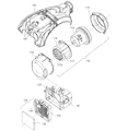
図2は、本発明による電気掃除機(vacuum cleaner)の主要構成要素を説明するための分解斜視図である。 FIG. 2 is an exploded perspective view for explaining main components of a vacuum cleaner according to the present invention.
図2に示すように、本発明による電気掃除機は、モータ組立体110、フィルタ組立体120、モータ組立体110とフィルタ組立体120を電気掃除機本体(図示せず)に固定させるためのブラケット130及び電気掃除機本体の上部を構成するカバー140を含む。
As shown in FIG. 2, the vacuum cleaner according to the present invention includes a
モータ組立体110は、吸引力を発生させるためのモータ112、モータ112を取り付けるための筐体114、及び吸音筒116を有する。吸音筒116は、筐体114内にモータ112の円筒状の体体を取り囲むように設けられる。筐体114内にモータ112と吸音筒116が設けられた後、筐体114は蓋119により密閉される。吸音筒116は、直径方向の断面形状が円形であり、底面117を具備するため、長手方向の断面形状は略U字状を有する(図4A参照)。吸音筒116の内壁部には、騷音を低減させるために、例えばフェルトからなる吸音材が付着されており、底面117にはメインフィルタ(図示せず)を経由した浄化された空気が通過する複数の空気通過孔117aが吸音筒116の底面117の円周方向に沿って一定間隔で形成されている。空気通過孔117aの直径は、底面117の下部に行くほど、すなわち空気の流れ方向に沿って次第に小さくなるように形成されている(図4A)。
The
フィルタ組立体120は、掃除機本体の後方部に備えられて空気通過孔117aを通過した空気から微細な異物をフィルタリングするための排気フィルタ122と、排気フィルタ122が取り付けられるフィルタ設置板124とを有する。フィルタ設置板124は、排気フィルタ122からの空気の一部を電気掃除機の内側に通過させるために、例えば後述する電気掃除機に電源を供給するための電源コードを巻き取るためのコードリール150に配設される開口部126を有する。
The
ブラケット130の一方には、モータ112が組み込められている筐体114が取り付けられ、他方には排気フィルタ122が設置されているフィルタ設置板124が取り付けられる。また、ブラケット130には、開口部126を通過した空気をコードリール150にガイドするためのガイド部132が設けられている。
A
カバー140の後部には、排気フィルタ122を経由した空気の一部を電気掃除機本体の上部にガイドするための複数の垂直のガイドリブ142が形成される。
A plurality of
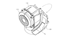
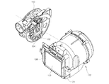
上記のように構成されるモータ組立体110とフィルタ組立体120とブラケット130が互いに組立てられた状態で、図3Aは空気の流動経路を矢印で示す図であり、図3Bはこの組立体へのコードリール150の装着を示す分解斜視図である。図3Bに示すように、コードリール150はモータ組立体110の一側に設けられる。
With the
図2、図3A及び図3Bから分かるように、排気フィルタ122を通過した空気の一部は、開口部126を通過した後、ブラケット130のガイド部132によりコードリール150側にガイドされて電源コードを冷却させる。また、コードリール150には、図3Bに示すように、ガイド部132を経由した空気を通過させるための通孔154と、この通孔154に空気をガイドするための曲げられたリブ152とが各通孔154の近傍にそれぞれ形成されている。
As can be seen from FIGS. 2, 3A, and 3B, a part of the air that has passed through the
以下、上記のように構成された本発明による電気掃除機の空流について説明する。 Hereinafter, the air flow of the vacuum cleaner according to the present invention configured as described above will be described.
モータ112を駆動して、吸引力が発生されると、異物を含む空気が吸引された後、埃などの異物はメインフィルタなどを通してフィルタリングされる。
When a suction force is generated by driving the
メインフィルタを通過して空気は、モータ112の筐体114の内側にガイドされ、モータ112の円筒状の本体を取り囲む吸音筒116を経由する。したがって、吸音筒116によりモータ112の騷音が低減される。吸音筒116の内周に吸音材が付着されている場合は、モータ112の密閉性がさらに向上する。その後、空気が空気通過孔117aを通過する。このとき、各空気通過孔117aの直径が、上述のように次第に小さくなるため、空気通過孔117aを通過する空気の速度は次第に増加する。その結果、速くなった空気の速度により発生される音波も大きくなり、音波の周波数が低周波から高周波に変わる。一般に高周波は低周波より、物体によって反射されやすいため、前記低周波から変えられた高周波は筐体114により反射されて、減衰される。これにより、電気掃除機の外部に伝達される騷音が低減する。
The air passing through the main filter is guided inside the
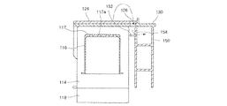
次に、上記のように吸音筒116を通過した空気は、ブラケット130及びフィルタ設置板124に取り付けられた排気フィルタ122を通過して排出される。空気が排気フィルタ122を通過することにより微細な異物がフィルタリングされる。その後、排気フィルタ112からの空気の一部は、図4Aに示すように、フィルタ設置板124に形成されている開口部126を通してブラケット130のガイド部132によりコードリール150に向かう。上記のように、ブラケット130のガイド部132によりガイドされてコードリール150に向かう空気は、コードリール150の側面に形成されているリブ152により通孔154にガイドされて、コードリール150を通過しながら、電源コードを冷却させる。
Next, the air that has passed through the
また、図4Bに示すように、フィルタ設置板124に取り付けられている排気フィルタ122からの空気の他の一部は、垂直のガイドリブ142によりブラケット130の上部、すなわち複数の電装品が取り付けられた筐体114の上方にガイドされ、電装品を冷却させる。
4B, another part of the air from the
また、排気フィルタ122からの空気の他の一部は、排気孔(図示せず)を通して電気掃除機の外部に排気される。
Further, another part of the air from the
このようにモータ112により吸引された空気は、排気フィルタ122を経由した後、一部の空気は開口部126とガイド部132によりコードリール150にガイドされて電源コードを冷却させ、同時に他の一部の空気は筐体114の上部にガイドされて電装品を冷却させる。また、排気フィルタからの空気の流れを分岐させることによって、電気掃除機の騷音を減少させることができる。
Thus, after the air sucked by the
110 モータ組立体
116 吸音筒
117a 空気通過孔
120 フィルタ組立体
130 ブラケット
132 ガイド部
140 カバー
142 ガイドリブ
150 コードリール
152 リブ
154 通孔
110
Claims (11)
前記本体内部に設置されて吸引力を発生させるモータを有するモータ組立体と、
前記本体内の後方部に備えられて前記モータ組立体を通過した空気から微細な異物をフィルタリングするための排気フィルタと、
前記排気フィルタを通過した空気の一部を本体内部にガイドするためのガイド部材と、
電源を供給するための電源コードが卷回されるコードリールを前記本体内部に含む電気掃除機であって、
前記ガイド部材はガイドされる空気の一部を前記コードリール側にガイドし、
前記コードリールは前記コードリール側にガイドされた空気を通過させるための複数の通孔及び前記複数の通孔の各々に空気をガイドするための複数の曲げられたガイドリブを有することを特徴とする電気掃除機。 The body,
A motor assembly having a motor installed inside the body to generate a suction force;
An exhaust filter for filtering fine foreign substances from the air that is provided in the rear part in the main body and has passed through the motor assembly;
A guide member for guiding a part of the air that has passed through the exhaust filter into the main body ;
A vacuum cleaner including a cord reel in which a power cord for supplying power is wound inside the main body,
The guide member guides a part of air to be guided to the cord reel side,
The cord reel includes a plurality of through holes for allowing air guided to the cord reel side and a plurality of bent guide ribs for guiding air into each of the plurality of through holes. Electric vacuum cleaner.
前記本体に設置されて吸引力を発生させるモータと、
前記本体の後方部に備えられて前記モータを通過した空気から微細な異物をフィルタリングするための排気フィルタと、
前記モータの騷音を防止するための吸音筒と、
前記モータと前記吸音筒が載置される筐体と、
前記排気フィルタが設置されるフィルタ設置板と、
前記筐体と前記フィルタ設置板を本体に固定させるためのブラケットと、
前記排気フィルタを通過した空気の一部を本体内部にガイドするためのガイドユニットと、
電源を供給するための電源コードが卷回されるコードリールを前記本体内部に含む電気掃除機であって、
前記ガイドユニットはガイドされる空気の一部を前記コードリール側にガイドし、
前記コードリールは前記コードリール側にガイドされた空気を通過させるための複数の通孔及び前記複数の通孔の各々に空気をガイドするための複数の曲げられたガイドリブを有することを特徴とする電気掃除機。 The body,
A motor that is installed in the main body and generates a suction force;
An exhaust filter for filtering fine foreign substances from the air that is provided in the rear part of the main body and has passed through the motor;
A sound-absorbing cylinder for preventing noise of the motor;
A housing on which the motor and the sound absorbing cylinder are placed;
A filter installation plate on which the exhaust filter is installed;
A bracket for fixing the housing and the filter installation plate to the main body;
A guide unit for guiding part of the air that has passed through the exhaust filter into the main body ;
A vacuum cleaner including a cord reel in which a power cord for supplying power is wound inside the main body,
The guide unit guides a part of air to be guided to the cord reel side,
The cord reel includes a plurality of through holes for allowing air guided to the cord reel side and a plurality of bent guide ribs for guiding air into each of the plurality of through holes. Electric vacuum cleaner.
Applications Claiming Priority (4)
| Application Number | Priority Date | Filing Date | Title |
|---|---|---|---|
| KR1020030096556A KR20050064941A (en) | 2003-12-24 | 2003-12-24 | Acoustic absorber for the vacuum cleaner |
| KR1020030096561A KR20050064946A (en) | 2003-12-24 | 2003-12-24 | Exhaust air guide for the vacuum cleaner |
| KR1020030096557A KR20050064942A (en) | 2003-12-24 | 2003-12-24 | Power cord cooler reel for the vacuum cleaner |
| KR1020030096563A KR100602239B1 (en) | 2003-12-24 | 2003-12-24 | Exhaust air guide for the vacuum cleaner |
Publications (2)
| Publication Number | Publication Date |
|---|---|
| JP2005185841A JP2005185841A (en) | 2005-07-14 |
| JP4105153B2 true JP4105153B2 (en) | 2008-06-25 |
Family
ID=34557567
Family Applications (1)
| Application Number | Title | Priority Date | Filing Date |
|---|---|---|---|
| JP2004371795A Expired - Fee Related JP4105153B2 (en) | 2003-12-24 | 2004-12-22 | Electric vacuum cleaner |
Country Status (4)
| Country | Link |
|---|---|
| US (1) | US7475449B2 (en) |
| EP (1) | EP1547508A3 (en) |
| JP (1) | JP4105153B2 (en) |
| CN (1) | CN1305426C (en) |
Families Citing this family (27)
| Publication number | Priority date | Publication date | Assignee | Title |
|---|---|---|---|---|
| US8978197B2 (en) * | 2009-03-13 | 2015-03-17 | Lg Electronics Inc. | Vacuum cleaner |
| US7987551B2 (en) * | 2005-12-10 | 2011-08-02 | Lg Electronics Inc. | Vacuum cleaner |
| US8544143B2 (en) * | 2005-12-10 | 2013-10-01 | Lg Electronics Inc. | Vacuum cleaner with removable dust collector, and methods of operating the same |
| US8012250B2 (en) * | 2005-12-10 | 2011-09-06 | Lg Electronics Inc. | Vacuum cleaner |
| US8281455B2 (en) * | 2005-12-10 | 2012-10-09 | Lg Electronics Inc. | Vacuum cleaner |
| US7882592B2 (en) * | 2005-12-10 | 2011-02-08 | Lg Electronics Inc. | Vacuum cleaner |
| US7749295B2 (en) * | 2005-12-10 | 2010-07-06 | Lg Electronics Inc. | Vacuum cleaner with removable dust collector, and methods of operating the same |
| US8404034B2 (en) * | 2005-12-10 | 2013-03-26 | Lg Electronics Inc. | Vacuum cleaner and method of controlling the same |
| KR100725515B1 (en) | 2005-12-15 | 2007-06-08 | 삼성광주전자 주식회사 | Vacuum cleaner having noise reducing structure of motor |
| EP1949842B1 (en) * | 2007-01-24 | 2015-03-04 | LG Electronics Inc. | Vacuum cleaner |
| US8528163B2 (en) * | 2009-02-12 | 2013-09-10 | Lg Electronics Inc. | Vacuum cleaner |
| US8151409B2 (en) * | 2009-02-26 | 2012-04-10 | Lg Electronics Inc. | Vacuum cleaner |
| GB2468299B (en) * | 2009-03-03 | 2012-06-20 | Dyson Technology Ltd | Noise reduction arrangement for a cleaning appliance. |
| US8713752B2 (en) * | 2009-03-13 | 2014-05-06 | Lg Electronics Inc. | Vacuum cleaner |
| US8402598B2 (en) * | 2009-06-11 | 2013-03-26 | Samsung Electronics Co., Ltd. | Upright-type vacuum cleaner |
| US8776312B2 (en) * | 2011-05-02 | 2014-07-15 | Techtronic Floor Care Technology Limited | Air flow path to cool a vacuum cleaner belt |
| CN102670131A (en) * | 2012-02-20 | 2012-09-19 | 江苏美的春花电器股份有限公司 | Mute dust collector |
| CN103027636A (en) * | 2012-12-31 | 2013-04-10 | 深圳市银星智能科技股份有限公司 | Intelligent dust collector |
| WO2015123538A1 (en) | 2014-02-14 | 2015-08-20 | Techtronic Industries Co. Ltd. | Vacuum cleaner with a separator received within the dirt collection chamber |
| WO2016065151A1 (en) | 2014-10-22 | 2016-04-28 | Techtronic Industries Co. Ltd. | Handheld vacuum cleaner |
| US9775483B2 (en) | 2014-10-22 | 2017-10-03 | Techtronic Industries Co. Ltd. | Vacuum cleaner having cyclonic separator |
| CN106714643B (en) | 2014-10-22 | 2019-05-21 | 创科实业有限公司 | Vacuum cleaner with cyclone separator |
| KR101509738B1 (en) * | 2014-10-27 | 2015-04-14 | 주식회사코네트인더스트리 | Dust-container assembly of vacuum cleaner |
| CN105342525A (en) * | 2015-03-02 | 2016-02-24 | 于长海 | Small household dust collector |
| KR102492164B1 (en) * | 2016-07-22 | 2023-01-30 | 삼성전자주식회사 | Vacuum cleaner |
| DE102017208965A1 (en) | 2017-05-29 | 2018-11-29 | BSH Hausgeräte GmbH | Blow-out channel for a vacuum cleaner and vacuum cleaner having this blow-out |
| CN210053306U (en) * | 2019-06-03 | 2020-02-11 | 东莞福莱仕智能电子科技有限公司 | Dust collector motor device and dust collector |
Family Cites Families (26)
| Publication number | Priority date | Publication date | Assignee | Title |
|---|---|---|---|---|
| US2323275A (en) * | 1941-01-16 | 1943-06-29 | Electrolux Corp | Cord-winding device |
| DE7908622U1 (en) | 1979-03-27 | 1980-02-21 | Licentia Patent-Verwaltungs-Gmbh, 6000 Frankfurt | vacuum cleaner |
| US4808090A (en) * | 1983-02-10 | 1989-02-28 | The Scott & Fetzer Company | Vacuum motor fan cover |
| JPH01305916A (en) | 1988-06-06 | 1989-12-11 | Hitachi Ltd | Electric cleaner |
| US4924039A (en) * | 1989-02-08 | 1990-05-08 | The Hoover Company | Cooled cord reel |
| JP2889665B2 (en) | 1990-07-20 | 1999-05-10 | 三洋電機株式会社 | Electric vacuum cleaner |
| JPH0549561A (en) | 1991-08-22 | 1993-03-02 | Matsushita Electric Ind Co Ltd | Cleaner |
| CN1096252A (en) | 1993-03-10 | 1994-12-14 | 周柏林 | A kind of envelope |
| JP3263498B2 (en) | 1993-09-28 | 2002-03-04 | 三洋電機株式会社 | Electric vacuum cleaner |
| JP3265120B2 (en) * | 1994-06-10 | 2002-03-11 | 三菱電機株式会社 | Method for eliminating harmful microorganisms in dust collection room of vacuum cleaner and vacuum cleaner |
| JP3268516B2 (en) * | 1995-05-29 | 2002-03-25 | 三菱電機株式会社 | Electric vacuum cleaner |
| KR970009718A (en) * | 1995-08-31 | 1997-03-27 | 배순훈 | Sound absorption room which lengthened exhaust channel of vacuum cleaner |
| SE9503753D0 (en) | 1995-10-25 | 1995-10-25 | Electrolux Ab | Device for a vacuum cleaner |
| CN2274932Y (en) * | 1996-04-17 | 1998-02-25 | 徐强 | Low noise cleaner |
| KR100190684B1 (en) * | 1996-05-17 | 1999-06-01 | 전주범 | Muffler chamber system of vacuum cleaner |
| KR0136300Y1 (en) | 1996-09-10 | 1999-02-01 | 최진호 | Motor of a vacuum cleaner |
| DE29623795U1 (en) | 1996-10-31 | 1999-12-30 | Aeg Hausgeraete Gmbh | Vacuum cleaner with integrated recessed grip |
| JP3924852B2 (en) * | 1997-07-24 | 2007-06-06 | 松下電器産業株式会社 | Electric vacuum cleaner |
| US6145160A (en) | 1998-11-20 | 2000-11-14 | Primus Holdings, L.P. | Tank-type vacuum cleaner |
| US6052862A (en) * | 1999-02-16 | 2000-04-25 | Multicraft International | Cord rewinder for a water filter type vacuum cleaner |
| JP2001029276A (en) * | 1999-07-23 | 2001-02-06 | Hitachi Ltd | Vacuum cleaner |
| JP2001087173A (en) | 1999-09-27 | 2001-04-03 | Matsushita Electric Ind Co Ltd | Vacuum cleaner |
| WO2001074025A1 (en) | 2000-03-24 | 2001-10-04 | Nilfisk-Advance A/S | A silencer for an air flow generator |
| KR100357516B1 (en) * | 2000-06-30 | 2002-10-18 | 삼성광주전자 주식회사 | Reflux cleaner |
| KR100389289B1 (en) | 2000-09-22 | 2003-06-27 | 주식회사 대우일렉트로닉스 | Vacuum cleaner |
| JP3890889B2 (en) | 2000-11-16 | 2007-03-07 | 三菱電機株式会社 | Electric vacuum cleaner |
-
2004
- 2004-12-21 US US11/016,865 patent/US7475449B2/en not_active Expired - Fee Related
- 2004-12-22 JP JP2004371795A patent/JP4105153B2/en not_active Expired - Fee Related
- 2004-12-22 EP EP04030514A patent/EP1547508A3/en not_active Withdrawn
- 2004-12-24 CN CNB2004101036793A patent/CN1305426C/en not_active Expired - Fee Related
Also Published As
| Publication number | Publication date |
|---|---|
| JP2005185841A (en) | 2005-07-14 |
| US7475449B2 (en) | 2009-01-13 |
| CN1305426C (en) | 2007-03-21 |
| EP1547508A3 (en) | 2007-07-11 |
| CN1636489A (en) | 2005-07-13 |
| EP1547508A2 (en) | 2005-06-29 |
| US20050138756A1 (en) | 2005-06-30 |
Similar Documents
| Publication | Publication Date | Title |
|---|---|---|
| JP4105153B2 (en) | Electric vacuum cleaner | |
| RU2328202C2 (en) | Vacuum cleaner (variant) | |
| JP4028872B2 (en) | Exhaust device for motor assembly and vacuum cleaner including the same | |
| US6804857B1 (en) | Apparatus for dampening the noise of a vacuum cleaner | |
| KR100809738B1 (en) | Vacuum cleaner | |
| KR100233513B1 (en) | Structure of air flow for vacuum cleaner | |
| KR20060117711A (en) | A motor assembly and a vacuum cleaner having the same | |
| CN104421223B (en) | Electric blowing machine assembly | |
| JP5899399B2 (en) | Electric vacuum cleaner | |
| JP2844987B2 (en) | Electric vacuum cleaner | |
| EP1723883A2 (en) | Exhausting apparatus of a motor assembly and a vacuum cleaner having the same | |
| KR100349292B1 (en) | Electric cleaner | |
| KR100231435B1 (en) | MCS(Muffler Chamber System) of Vacuum Cleaner | |
| JP4630365B2 (en) | Electric vacuum cleaner | |
| KR960014580B1 (en) | Structure for cooling electric power cord of cord -reel device for a vacuum cleaner | |
| KR100602239B1 (en) | Exhaust air guide for the vacuum cleaner | |
| JP2000120599A (en) | Motor-driven blower and vacuum cleaner mounted with it | |
| KR200220648Y1 (en) | Exhaust duct for vacuum cleaner | |
| KR200205691Y1 (en) | Niose reducing device of casing for vacuum cleaner | |
| KR0136318B1 (en) | Mufler chamber system of a vacuum cleaner | |
| KR19990033890A (en) | Sound absorption room of vacuum cleaner | |
| KR100231436B1 (en) | MCS(Muffler Chamber System) of Vacuum Cleaner | |
| KR950012122B1 (en) | A low-noice vacuum cleaner | |
| JP2003325389A (en) | Vacuum cleaner | |
| JP2024006431A (en) | vacuum cleaner |
Legal Events
| Date | Code | Title | Description |
|---|---|---|---|
| A131 | Notification of reasons for refusal |
Free format text: JAPANESE INTERMEDIATE CODE: A131 Effective date: 20070717 |
|
| A521 | Written amendment |
Free format text: JAPANESE INTERMEDIATE CODE: A523 Effective date: 20071016 |
|
| TRDD | Decision of grant or rejection written | ||
| A01 | Written decision to grant a patent or to grant a registration (utility model) |
Free format text: JAPANESE INTERMEDIATE CODE: A01 Effective date: 20080304 |
|
| A61 | First payment of annual fees (during grant procedure) |
Free format text: JAPANESE INTERMEDIATE CODE: A61 Effective date: 20080326 |
|
| R150 | Certificate of patent or registration of utility model |
Free format text: JAPANESE INTERMEDIATE CODE: R150 |
|
| FPAY | Renewal fee payment (event date is renewal date of database) |
Free format text: PAYMENT UNTIL: 20110404 Year of fee payment: 3 |
|
| LAPS | Cancellation because of no payment of annual fees |