JP4101501B2 - Compound gas sensor element - Google Patents
Compound gas sensor element Download PDFInfo
- Publication number
- JP4101501B2 JP4101501B2 JP2001347935A JP2001347935A JP4101501B2 JP 4101501 B2 JP4101501 B2 JP 4101501B2 JP 2001347935 A JP2001347935 A JP 2001347935A JP 2001347935 A JP2001347935 A JP 2001347935A JP 4101501 B2 JP4101501 B2 JP 4101501B2
- Authority
- JP
- Japan
- Prior art keywords
- gas
- measured
- cell
- oxygen
- side electrode
- Prior art date
- Legal status (The legal status is an assumption and is not a legal conclusion. Google has not performed a legal analysis and makes no representation as to the accuracy of the status listed.)
- Expired - Lifetime
Links
Images


Landscapes
- Measuring Oxygen Concentration In Cells (AREA)
Description
【0001】
【技術分野】
本発明は,被測定ガス中に含まれる特定ガス成分濃度を検出するセンサセルと被測定ガスの空燃比を検出する空燃比検出セルとを有する複合ガスセンサ素子に関する。
【0002】
【従来技術】
例えば,自動車等においては,エンジンから排出される排気ガスが触媒等によって浄化されているかを監視するために,この排気ガス中のNOx濃度の検出を行っている。
図13に示すごとく,NOx濃度を検出するガスセンサ素子90として,酸素ポンプセル97により酸素をポンピングして被測定ガス中の酸素濃度を調整し,NOx分解活性を有する電極を備えたセンサセル94によって,NOx濃度を検出するものがある。
【0003】
このガスセンサ素子90においては,固体電解質体95に一対の電極971,972を配置して構成した酸素ポンプセル97において,一対の電極971,972の間に電圧を印加して,被測定ガスを導入した第1被測定ガス室71における酸素濃度を調整する。この調整に当たっては,固体電解質体96に一対の電極931,932を配置して構成した酸素モニタセル93により,第1被測定ガス室71における酸素濃度を検出して,この検出した酸素濃度が所望の値となるように,上記酸素ポンプセル97に印加する電圧がフィードバック制御される。
【0004】
そして,上記第1被測定ガス室71において酸素濃度を調整された被測定ガスが第2被測定ガス室72に流れる。この第2被測定ガス室72には,固体電解質体96に一対の電極941,942を配置して構成すると共に一方の電極941がNOxに対する分解活性を有するセンサセル94が設けてある。
そして,このセンサセル94の一対の電極941,942の間に電圧を印加し,NOxの分解に伴い流れる酸素イオン電流を検出することにより,NOx濃度を検出することができる。
【0005】
【解決しようとする課題】
ところで,内燃機関の制御において,被測定ガス中のNOx濃度に加えて,被測定ガスの空燃比を検出できる複合ガスセンサ素子へのニーズが高まっている。例えば,特開平11−72477号公報に示すごとく,複合ガスセンサ素子によって,上記NOx濃度の検出と上記被測定ガスの空燃比の検出とを同時に行うことは可能である。
【0006】
しかしながら,複合ガスセンサ素子において,上記NOx濃度の検出と上記被測定ガスの空燃比の検出とを同時に行うためには,これらの信号を外部回路に取り出すために,複合ガスセンサ素子における端子部の数が多くなってしまう。そのため,複合ガスセンサ素子の構造が複雑になってしまう。
【0007】
本発明は,かかる従来の問題点に鑑みてなされたもので,端子部の数を少なくすることができると共に,構造が簡単な複合ガスセンサ素子を提供しようとするものである。
【0008】
【課題の解決手段】
第1の発明は,所定の拡散抵抗の下に被測定ガスを導入する被測定ガス室と,
該被測定ガス室に曝されるポンプ電極と,上記被測定ガスに曝されるポンプ電極との一対の電極を固体電解質体に配置して構成されると共に,上記一対の電極の間に電圧を印加することにより,上記被測定ガス室における酸素濃度を調整する酸素ポンプセルと,
上記被測定ガス室に曝される被測定ガス室側電極と,基準ガスに曝される基準ガス側電極との一対の電極を固体電解質体に配置して構成されると共に,上記被測定ガス中に含まれる特定ガス成分濃度を検出するセンサセルと,
上記被測定ガスに曝される被測定ガス側電極と,基準ガスに曝される基準ガス側電極との一対の電極を固体電解質体に配置して構成されると共に,当該一対の電極間に生じる起電力値により上記被測定ガスの空燃比を検出する空燃比検出セルとを有し,
上記酸素ポンプセルにおける上記被測定ガスに曝されるポンプ電極と上記空燃比検出セルにおける被測定ガス側電極,又は上記センサセルにおける基準ガス側電極と上記空燃比検出セルにおける基準ガス側電極との少なくともいずれか一方を共通化したことを特徴とする複合ガスセンサ素子にある(請求項1)。
【0009】
本発明における複合ガスセンサ素子は,上記センサセルにより上記被測定ガス中に含まれる特定ガス成分濃度を検出すると共に上記空燃比検出セルにより上記被測定ガスの空燃比を検出する複数のガス濃度の検出機能を有している。
また,上記酸素ポンプセル,センサセル及び空燃比検出セルの各電極は,複合ガスセンサ素子の一部に端子部を設けて,外部回路に接続される。
【0010】
上記酸素ポンプセルにおける被測定ガスに曝されるポンプ電極と上記空燃比検出セルにおける被測定ガス側電極との共通化を行った場合,この共通化を行った共通電極は,上記被測定ガス室に導入される前の被測定ガスに接触している。つまり,上記酸素ポンプセルにおける被測定ガスに曝されるポンプ電極と上記空燃比検出セルにおける被測定ガス側電極とは,それぞれ上記被測定ガスに接触させて用いる電極であるため,上記のような共通電極とすることができる。そのため,本来ならば,上記2つの電極を複合ガスセンサ素子の外部回路に接続するためには2つの端子部が必要になるところ,1つの端子部で外部回路に接続することができる。
【0011】
また,上記センサセルにおける基準ガス側電極と上記空燃比検出セルにおける基準ガス側電極との共通化を行った場合,この共通化を行った共通電極は,上記基準ガスに接触している。つまり,上記センサセルにおける基準ガス側電極と上記空燃比検出セルにおける基準ガス側電極とは,それぞれ基準ガスに接触させて用いる電極であるため,上記のような共通電極とすることができる。そのため,本来ならば,上記2つの電極を複合ガスセンサ素子の外部回路に接続するためには2つの端子部が必要になるところ,1つの端子部で外部回路に接続することができる。
このように,本発明によれば,複合ガスセンサ素子における端子部の数を少なくすることができ,複合ガスセンサ素子の構造を簡単にすることができる。
【0012】
第2の発明は,所定の拡散抵抗の下に被測定ガスを導入する被測定ガス室と,
該被測定ガス室に曝されるポンプ電極と,基準ガスに曝されるポンプ電極との一対の電極を固体電解質体に配置して構成されると共に,上記一対の電極の間に電圧を印加することにより,上記被測定ガス室における酸素濃度を調整する酸素ポンプセルと,
上記被測定ガス室に曝される被測定ガス室側電極と,基準ガスに曝される基準ガス側電極との一対の電極を固体電解質体に配置して構成されると共に,上記被測定ガス中に含まれる特定ガス成分濃度を検出するセンサセルと,
上記被測定ガスに曝される被測定ガス側電極と,基準ガスに曝される基準ガス側電極との一対の電極を固体電解質体に配置して構成されると共に,当該一対の電極間に生じる起電力値により上記被測定ガスの空燃比を検出する空燃比検出セルと,
上記被測定ガス室に曝される被測定ガス室側電極と基準ガスに曝される基準ガス側電極との一対の電極を固体電解質体に配置して構成されると共に,上記被測定ガス室における酸素濃度を検出する酸素モニタセルを有しており,
上記酸素ポンプセルにおける基準ガスに曝されるポンプ電極,上記センサセルにおける基準ガス側電極,上記空燃比検出セルにおける基準ガス側電極のうち少なくともいずれか1つと,上記酸素モニタセルにおける基準ガス側電極とを共通化したことを特徴とする複合ガスセンサ素子にある(請求項3)。
【0013】
本発明における複合ガスセンサ素子も,上記発明と同様に上記センサセルにより上記被測定ガス中に含まれる特定ガス成分濃度を検出する機能と,上記空燃比検出セルにより上記被測定ガスの空燃比を検出する機能との複数のガス濃度の検出機能を有している。
また,上記酸素ポンプセル,センサセル及び空燃比検出セルの各電極は,複合ガスセンサ素子の一部に端子部を設けて,外部回路に接続される。
【0014】
上記酸素ポンプセルにおける基準ガスに曝されるポンプ電極,上記センサセルにおける基準ガス側電極,上記空燃比検出セルにおける基準ガス側電極のうち,全てあるいはいずれか2つの共通化を行った場合,この共通化を行った共通電極は,上記各セルにおいてガス濃度の検出を行う際の基準となる基準ガスに接触している。つまり,上記酸素ポンプセルにおける基準ガスに曝されるポンプ電極,上記センサセルにおける基準ガス側電極,及び上記空燃比検出セルにおける基準ガス側電極は,それぞれ上記基準ガスに接触させて用いる電極であるため,上記のような共通電極とすることができる。
【0015】
そのため,本来ならば,上記2つ又は3つの電極を複合ガスセンサ素子の外部回路に接続するためには2つ又は3つの端子部が必要になるところ,1つ又は2つの端子部で外部回路に接続することができる。
このように,本発明によっても,複合ガスセンサ素子における端子部の数を少なくすることができ,複合ガスセンサ素子の構造を簡単にすることができる。
【0016】
【発明の実施の形態】
上記複合ガスセンサ素子において,上記センサセルにおいて検出を行う特定ガス成分は,NOx又は炭化水素として,上記センサセルはこれらの濃度を検出することができる。
また,上記複合センサ素子は,エンジンの空燃比制御,触媒制御又は劣化検知等を行うために使用することができる。
【0017】
上記第1の発明においては,上記複合ガスセンサ素子は,上記被測定ガス室に曝される被測定ガス室側電極と基準ガスに曝される基準ガス側電極との一対の電極を固体電解質体に配置して構成されると共に上記被測定ガス室における酸素濃度を検出する酸素モニタセルを有しており,上記センサセルにおける基準ガス側電極又は上記空燃比検出セルにおける基準ガス側電極の少なくともいずれか一方と,上記酸素モニタセルにおける基準ガス側電極とを共通化することが好ましい(請求項2)。
【0018】
この場合,上記酸素モニタセルによって,上記被測定ガス室における酸素濃度の検出を行い,この被測定ガス室における酸素濃度の監視を行うことができる。
また,この場合,上記センサセルにおける基準ガス側電極,上記空燃比検出セルにおける基準ガス側電極,及び上記酸素モニタセルにおける基準ガス側電極は,いずれも基準ガスに接触させる電極であるため,共通化した共通電極とすることができる。そのため,上記複合ガスセンサ素子が酸素モニタセルを有する場合でも,この複合ガスセンサ素子における端子部の数を少なくすることができ,複合ガスセンサ素子の構造を簡単にすることができる。
【0019】
上記第2の発明においては,上記複合ガスセンサ素子は,上記被測定ガス室に曝される被測定ガス室側電極と基準ガスに曝される基準ガス側電極との一対の電極を固体電解質体に配置して構成されると共に上記被測定ガス室における酸素濃度を検出する酸素モニタセルを有しており,上記酸素ポンプセルにおける基準ガスに曝されるポンプ電極,上記センサセルにおける基準ガス側電極,上記空燃比検出セルにおける基準ガス側電極のうち少なくともいずれか1つと,上記酸素モニタセルにおける基準ガス側電極とを共通化している。
【0020】
この場合,上記酸素モニタセルによって,上記被測定ガス室における酸素濃度の検出を行い,この被測定ガス室における酸素濃度の監視を行うことができる。
また,この場合,上記酸素ポンプセルにおける基準ガスに曝されるポンプ電極,上記センサセルにおける基準ガス側電極,上記空燃比検出セルにおける基準ガス側電極,及び上記酸素モニタセルにおける基準ガス側電極は,いずれも基準ガスに接触させる電極であるため,共通化した共通電極とすることができる。そのため,上記複合ガスセンサ素子が酸素モニタセルを有する場合でも,この複合ガスセンサ素子における端子部の数を少なくすることができ,複合ガスセンサ素子の構造を簡単にすることができる。
【0021】
また,上記第1の発明及び第2の発明において,上記複合ガスセンサ素子が上記酸素モニタセルを有している場合には,上記酸素ポンプセルは,上記酸素モニタセルにおいて検出する酸素濃度が所望の値となるように,上記印加する電圧を制御するよう構成することができる(請求項4)。
この場合,上記酸素モニタセルにおいて検出する酸素濃度が所望の値となるように上記酸素ポンプセルに印加する電圧をフィードバック制御することができる。そのため,上記被測定ガス室における酸素濃度を容易に調整することができる。
【0022】
また,上記第1の発明及び第2の発明において,上記複合ガスセンサ素子が上記酸素モニタセルを有している場合には,上記酸素モニタセルは,該酸素モニタセルに発生する起電力に基づいて,上記被測定ガス室における酸素濃度を検出するよう構成することができる(請求項5)。
この場合,上記起電力に基づいて,容易に上記被測定ガス室における酸素濃度を検出することができる。
【0023】
また,上記第1の発明及び第2の発明において,上記複合ガスセンサ素子が上記酸素モニタセルを有している場合には,上記酸素モニタセルは,該酸素モニタセルに流れる酸素イオン電流に基づいて上記被測定ガス室における酸素濃度を検出するよう構成することができる(請求項6)。
この場合,上記酸素イオン電流に基づいて,容易に上記被測定ガス室における酸素濃度を検出することができる。
【0024】
【実施例】
以下に,図面を用いて本発明の実施例につき説明する。
(実施例1)
図1に示すごとく,本例における複合ガスセンサ素子1は,酸素をポンピングして被測定ガス中の酸素濃度を調整する酸素ポンプセル2と,被測定ガス中の酸素濃度を検出する酸素モニタセル3と,被測定ガス中の特定ガス成分濃度を検出するセンサセル4と,被測定ガスの空燃比を検出する空燃比検出セル20とを有している。
【0025】
上記複合ガスセンサ素子1は,上記被測定ガスを所定の拡散抵抗の下に導入する被測定ガス室7を有している。
上記酸素ポンプセル2は,上記被測定ガス室7に曝されるポンプ電極21と,上記被測定ガスに曝されるポンプ電極22との一対の電極21,22を固体電解質体5に配置して構成される。そして,酸素ポンプセル2は,上記一対の電極21,22の間に電圧を印加することにより,上記被測定ガス室7における酸素濃度を調整する。
上記酸素モニタセル3は,上記被測定ガス室7に曝される被測定ガス室側電極31と,基準ガスに曝される基準ガス側電極32との一対の電極31,32を固体電解質体6に配置して構成される。そして,酸素モニタセル3は,上記被測定ガス室7における酸素濃度を検出する。
【0026】
上記センサセル4は,上記被測定ガス室7に曝される被測定ガス室側電極41と,基準ガスに曝される基準ガス側電極42との一対の電極41,42を固体電解質体6に配置して構成される,そして,センサセル4は,上記被測定ガス室7における特定ガス成分濃度を検出する。
また,上記空燃比検出セル20は,上記被測定ガスに曝される被測定ガス側電極201と,基準ガスに曝される基準ガス側電極202との一対の電極201,202により構成され,被測定ガスの空燃比を検出する。
【0027】
また,本例においては,上記空燃比検出セル20における被測定ガス側電極201と,上記酸素ポンプセル2における上記ポンプ電極22とが共通化されている。
また,上記酸素モニタセル3における基準ガス側電極32と,上記センサセル4における基準ガス側電極42と,上記空燃比検出セル20における基準ガス側電極202との3つの電極が共通化されている。
【0028】
以下に,これを詳説する。
本例における複合ガスセンサ素子1においては,自動車のエンジンの排気ガスを被測定ガスとし,該被測定ガス中に含まれるNOx濃度を検出する。つまり,上記センサセル4において検出する特定ガスはNOxとし,センサセル4は,上記被測定ガス室7におけるNOx濃度を検出する。
また,複合ガスセンサ素子1においては,酸素濃度に依存する起電力によりエンジンの燃焼室における空燃比を検出する。つまり,上記空燃比セル20においては酸素濃度に依存した起電力が発生し,この起電力により空燃比の検出を行う。
【0029】
また,本例の複合ガスセンサ素子1は,検出したNOx濃度及び空燃比を利用して,エンジンの燃焼制御を最適に行うために使用するものである。
図1に示すごとく,上記酸素ポンプセル2におけるポンプ電極22と上記空燃比検出セル20における被測定ガス側電極201とは,同一の極板上に共通電極200として形成されている。
【0030】
また,上記酸素モニタセル3における基準ガス側電極32と上記センサセル4における基準ガス側電極42と上記空燃比検出セル20における基準ガス側電極202とは,同一の極板上に共通電極300として形成されている。そして,この共通電極300は,上記酸素モニタセル3における被測定ガス室側電極31と上記センサセル4における被測定ガス室側電極41とに対向して設けられている。
【0031】
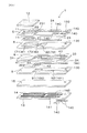
図2に本例における複合ガスセンサ素子1を分解した状態の斜視図を示す。
同図に示すごとく,複合ガスセンサ素子1は,酸素ポンプセル2を構成するためのシート状の固体電解質体5と,酸素モニタセル3及びセンサセル4を構成するためのシート状の固体電解質体6と,被測定ガス室7を形成するためのシート状のスペーサ8と,基準ガス室100を形成するためのシート状のスペーサ9と,これらを加熱するセラミックヒータ10とを,順次積層して構成されている。
【0032】
また,酸素ポンプセル2を構成する固体電解質体5と,酸素モニタセル3及びセンサセル4を構成する固定電解質体6と,スペーサ8とは,それぞれジルコニアやセリア等の酸素イオン導電性を有する電解質よりなる。
また,上記スペーサ9はアルミナ等の絶縁材料よりなる。
【0033】
被測定ガス室7は,被測定ガス存在空間110より被測定ガスが導入される空間であり,被測定ガス存在空間110に対して上流側に位置する第1被測定ガス室71と,下流側に位置する第2被測定ガス室72とに分割して形成してある。そして,第1被測定ガス室71と第2被測定ガス室72との間は,第1被測定ガス室71から第2被測定ガス室72に流れる被測定ガスを律速する絞り部73が設けてある。
上記第1被測定ガス室71,第2被測定ガス室72及び絞り部73は,それぞれ固体電解質体5と固体電解質体6との間に位置するスペーサ8の抜き穴81,82,83により形成されている。
【0034】
上記被測定ガス存在空間110から被測定ガス室71には,ピンホール11を介して被測定ガスを導入するようになっており,また,固体電解質体5における被測定ガス存在空間110側の表面には,上記ピンホール11の開口部を覆うようにして多孔質保護層12が設けてある。
本例においては,ピンホール11と多孔質保護層12とにより,被測定ガスの流動速度を律速し,被測定ガスを所定の拡散抵抗の下に被測定ガス室7に導入するようになっている。
【0035】
上記ピンホール11の大きさは,これを通過して第1被測定ガス室71及び第2被測定ガス室72に導入される被測定ガスの拡散速度が所定の速度となるように,適宜設定される。また,上記多孔質保護層12は,酸素ポンプセル2における一対の電極21,22,酸素モニタセル3の電極31及びセンサセル4の電極41の被毒や,ピンホール11に目詰まり等が発生することを防止する。この多孔質保護層12は,多孔質アルミナ等より形成してある。
なお,上記被測定ガスを所定の拡散抵抗の下に被測定ガス室7に導入するための別の方法として,上記ピンホール11を形成する位置に,上記多孔質アルミナ等よりなる多孔質体を設けてもよい。
【0036】
基準ガス室100には,上記酸素濃度,NOx濃度及び空燃比の検出を行う際の基準となる基準ガスとして,略一定の酸素濃度をもつ大気が導入される。また,基準ガス室100は,通路部101を介して基準ガスを導入する基準ガス空間120に連通されている。
また,基準ガス室100は,固体電解質体6に対してスペーサ8が対向する側とは反対側に位置するスペーサ9において,このスペーサ9に設けた抜き穴91により形成されており,通路部101は,スペーサ9に設けた溝92により形成されている。
【0037】
上記酸素ポンプセル2は,固体電解質体5と,この固体電解質体5を挟むように対向配置されたポンプ電極21及びポンプ電極22の一対の電極とにより構成される。
また,一方のポンプ電極21は,固体電解質体5においてスペーサ8と対向する側の表面に,上記第1被測定ガス室71に接して設けられている。また,他方のポンプ電極22は,固体電解質体5において被測定ガス存在空間110と対向する側の表面に,上記多孔質保護層12を介して被測定ガス存在空間110と接して設けられている。
【0038】
上記酸素モニタセル3は,固体電解質体6と,この固体電解質体6を挟むように対向配置された被測定ガス室側電極31及び基準ガス側電極32の一対の電極とにより構成される。
また,被測定ガス室側電極31は,固体電解質体6においてスペーサ8と対向する側の表面に,上記第1被測定ガス室71に接して設けられている。また,基準ガス側電極32は,固体電解質体6においてスペーサ9と対向する側の表面に,上記基準ガス室100と接して設けられている。
【0039】
上記センサセル4は,固体電解質体6と,この固体電解質体6を挟むように対向配置された被測定ガス室側電極41及び基準ガス側電極42の一対の電極とにより構成される。
また,被測定ガス室側電極41は,固体電解質体6においてスペーサ8と対向する側の表面に,上記第2被測定ガス室72に接して設けられている。また,基準ガス側電極42は,固体電解質体6においてスペーサ9と対向する側の表面に,上記基準ガス室100と接して設けられている。
【0040】
上記センサセル4の被測定ガス室側電極41は,上記被測定ガス中におけるNOxの分解を促進させるために,NOx分解活性を有していることが好ましい。
本例においては,センサセル4の被測定ガス室側電極41は,Pt及びRhを金属主成分とする多孔質サーメット電極としている。この際,この多孔質サーメット電極の金属成分におけるRhの含有量は10〜50重量%程度とすることが好ましい。本例においては,これにより,NOx分解活性が高い電極を構成することができる。
【0041】
上記酸素ポンプセル2のポンプ電極21及び酸素モニタセル3の被測定ガス室側電極31は,上記被測定ガス中におけるNOxの分解を抑制するために,上記センサセル4の被測定ガス室側電極41に比べて,NOx分解活性の低い電極を用いることが好ましい。
本例においては,酸素ポンプセル2のポンプ電極21と酸素モニタセル3の被測定ガス室側電極31は,Pt及びAuを金属主成分とする多孔質サーメット電極としている。この際,この多孔質サーメット電極の金属成分におけるAuの含有量は1〜10重量%程度とすることが好ましい。本例においては,これにより,NOx分解活性がほとんどない電極を構成することができる。
【0042】
また,上記酸素ポンプセル2のポンプ電極22には,Ptを含有する多孔質サーメット電極を用いる。
また,上記酸素モニタセル3の基準ガス側電極32と上記センサセル4の基準ガス側電極42と上記空燃比検出セル20の基準ガス側電極202との3つの電極を共通化した共通電極300にも,Ptを含有する多孔質サーメット電極を用いる。
【0043】
また,図2に示すごとく,上記ポンプ電極21にはリード部23が,上記共通電極200にはリード部24が,上記被測定ガス室側電極31,41にはそれぞれリード部33,43が,共通電極300にはリード部34(44)が一体的に形成されている。
また,固体電解質体5又は固体電解質体6と上記リード部23,24,33,34(44),43との間には,アルミナ等の絶縁層(図示略)を形成しておくことが好ましい。
【0044】
上記セラミックヒータ10は,アルミナ製のヒータシート13の表面に通電発熱するヒータ電極14をパターニング形成し,このヒータ電極14を形成した表面に絶縁性を有するアルミナ層15を重ね合わせて構成する。
また,このセラミックヒータ10は,上記スペーサ9に対して,このスペーサ9において固体電解質体6に対向しない側の表面に対向して配置されている。
上記ヒータ電極14には,Ptとアルミナ等のセラミックスとのサーメットが用いられている。また,セラミックヒータ10は,ヒータ電極14を外部からの給電により発熱させ,上記酸素ポンプセル2,酸素モニタセル3,センサセル4及び空燃比検出セル20をガス濃度の検出に適した活性化温度まで加熱するものである。
【0045】
また,上記酸素ポンプセル2における一対の電極21,22,上記酸素モニタセル3の一対の電極31,32,上記センサセル4の一対の電極41,42,及びヒータ電極14における一対の端部141,142は,それぞれ上記各リード部23,24,33,34(44),43及びスルーホール130を介して,複合ガスセンサ素子1の両側面(固体電解質体5の外側表面及びヒータシート13の外側表面)に設けられた端子部であるセンサ端子140に接続されている。
そして,このセンサ端子140にはコネクタを介して圧着やろう付け等によりリード線が接続され,外部回路と,上記各セル2,3,4又はセラミックヒータ10との間で電気信号を入出力させることが可能となっている(図示略)。
【0046】
固体電解質体5,6,スペーサ8,9,ヒータシート13及びアルミナ層15は,ドクターブレード法や押し出し成形法等により,シート形状に成形することができる。
また,上記の各電極21,22,31,32,41,42,各リード部23,24,33,34,43,44,及びセンサ端子140は,スクリーン印刷等により形成することができる。
また,上記固体電解質体5,6,スペーサ8,9,多孔質保護層12,ヒータシート13及びアルミナ層15は,積層して焼成することにより一体化することができる。
【0047】
また,図1に示すごとく,上記酸素ポンプセル2には,該酸素ポンプセル2に電圧を印加するための電源25を有する酸素ポンプセル回路240が設けられている。同図において,電源25は,被測定ガス存在空間110側のポンプ電極22がプラス極として記載してあるが,実際には被測定ガス室7における酸素濃度を調整する際に,プラス極とマイナス極とが入れ替わることもある。
【0048】
また,上記酸素モニタセル3には,該酸素モニタセル3における起電力である電圧を検出するための電圧検出手段37を有する酸素モニタセル回路340が設けてある。
また,上記センサセル4には,該センサセル4に電圧を印加するための電源45とセンサセル4に流れる酸素イオン電流を検出するための電流検出手段46とを有するセンサセル回路440が設けてある。
【0049】
また,上記共通電極200と上記共通電極300との間には,空燃比検出セル20における起電力を検出するための電圧検出手段207を有する空燃比検出セル回路204が設けてある。
また,図示は省略するが,上記各電源25,45,各電圧検出手段37,207及び電流検出手段46は,外部回路に接続されており,この外部回路における演算手段によって,各制御及び演算が行われる。
また,上記電圧検出手段37によって検出した電圧値は,制御信号線250を介して上記外部回路に送信され,この外部回路における演算手段は制御信号線250を介して上記電源25の電圧を制御するようになっている。
【0050】
次に,上記複合ガスセンサ素子1において,NOx濃度及び空燃比を検出する方法について詳説する。
本例の複合ガスセンサ素子1により,NOx濃度の検出を行うに当っては,エンジンの排気ガスである被測定ガスが,多孔質保護層12及びピンホール11を通過して第1被測定ガス室71に導入される。
【0051】
そして,上記酸素ポンプセル2における一対のポンプ電極21,22の間に電圧を印加して,上記被測定ガス室71と上記被測定ガス存在空間110との間で酸素を入出させるポンピング作用により,第1被測定ガス室71に導入された被測定ガス中に含まれる酸素濃度を調整する。
【0052】
上記ポンピング作用による酸素濃度の調整は,具体的には以下のようにして行われる。
即ち,一対のポンプ電極21,22に,被測定ガス存在空間110側のポンプ電極22がプラス極となるように電圧を印加すると,上記第1被測定ガス室71側のポンプ電極21上で被測定ガス中の酸素が還元されて酸素イオンとなる。そして,この酸素イオンが上記ポンプ電極21から上記ポンプ電極22に向けて流れることにより,上記第1被測定ガス室71における酸素が排出され,第1被測定ガス室71における酸素濃度が低下する。
【0053】
逆に,第1被測定ガス室71側のポンプ電極21がプラス極となるように電圧を印加すると,被測定ガス存在空間110側のポンプ電極22上で被測定ガス中の酸素や水蒸気が還元されて酸素イオンとなる。そして,この酸素イオンが上記ポンプ電極22から上記ポンプ電極21に向けて流れることにより,上記第1被測定ガス室71に酸素が取り込まれ,第1被測定ガス室71における酸素濃度が上昇する。
このような,ポンピング作用を利用して,上記酸素ポンプセル2は,上記被測定ガス中の酸素濃度を,被測定ガスに含まれるNOx濃度を検出するのに適した濃度に調整する。
【0054】
上記酸素モニタセル3においては,被測定ガス室側電極31と基準ガス側電極32とに接触するガス同士の間の酸素濃度の違いにより発生する起電力を検出する。即ち,この起電力は,酸素濃度が高い電極から低い電極に向けて酸素イオン電流が流れようとすることにより発生するもので,上記基準ガス側電極32は酸素濃度が略一定の基準ガスに接触しているため,被測定ガス室側31に接触する被測定ガスにおける酸素濃度の変化が起電力の変化として検出される。
【0055】
そして,上記酸素モニタセル3における起電力が一定の値になるように,上記酸素ポンプセル2に印加する電圧をフィードバック制御することにより,容易に上記被測定ガス中に含まれる酸素濃度を調整することができる。例えば,酸素モニタセル3に発生する起電力が0.3Vとなるように,上記酸素ポンプセル2に印加する電圧を変化させることができる。
【0056】
また,上記センサセル4における被測定ガス室側電極41と基準ガス側電極42とによる一対の電極との間には,限界電流特性を示す値の電圧を印加する。
例えば,上記センサセル4に印加する電圧の値としては,限界電流特性を示す値として0.40Vとすることができる。
【0057】
上記センサセル4における被測定ガス室側電極41は,上記のごとくNOx分解活性が高い性質を有している。そのため,上記被測定ガス室側電極41においては,被測定ガス中に含まれるNOxが分解反応を起こす。
具体的には,例えば,図1に示すごとく,上記基準ガス室100に接する基準ガス側電極42がプラス極となるように電圧を印加すると,上記第2被測定ガス室72に接する被測定ガス室側電極41上で被測定ガス中のNOxや酸素が還元されて酸素イオンとなり,この酸素イオンが被測定ガス室側電極41から基準ガス側電極42に向けて流れる。
【0058】
本実施例では,酸素モニタセル3と酸素ポンプセル2とにより,被測定ガス室7内の酸素濃度を一定に制御している。したがって,NOxの分解反応の量に応じて,上記酸素イオン電流の大きさが変化し,これによりNOx濃度を検出することができる。
【0059】
また,上記空燃比検出セル20においては,被測定ガス側電極201と基準ガス側電極202とに接触するガス同士の間の酸素濃度の違いにより発生する起電力を検出する。このとき,上記基準ガス側電極202は酸素濃度が略一定の基準ガスに接触しているため,上記被測定ガス室7に導入される前の被測定ガスにおける酸素濃度の変化が起電力の変化として検出される。そして,この起電力の値から,空燃比を検出することができる。
【0060】
本例においては,上記のごとく,上記空燃比検出セル20における被測定ガス側電極201と,上記酸素ポンプセル2における上記ポンプ電極22とが共通電極200により共通化されている。また,上記酸素モニタセル3における基準ガス側電極32と,上記センサセル4における基準ガス側電極42と,上記空燃比検出セル20における基準ガス側電極202との3つの電極が共通電極300により共通化されている。
【0061】
上記空燃比検出セル20における被測定ガス側電極201と,上記酸素ポンプセル2における上記ポンプ電極22とは,ともに上記被測定ガス室7に導入される前の被測定ガスに曝される電極であるため,共通化することができる。そのため,本来ならば,上記2つの電極201,22を複合ガスセンサ素子1の外部回路に接続するためには2つのセンサ端子140が必要になるところ,1つのセンサ端子140で外部回路に接続することができる。
【0062】
また,上記酸素モニタセル3における基準ガス側電極32と,上記センサセル4における基準ガス側電極42と,上記空燃比検出セル20における基準ガス側電極202とは,いずれも上記基準ガス室に曝される電極であるため,共通化することができる。そのため,本来ならば,上記3つの電極32,42,202を複合ガスセンサ素子1の外部回路に接続するためには3つのセンサ端子140が必要になるところ,1つのセンサ端子140で外部回路に接続することができる。
それ故,本例における複合ガスセンサ素子1によれば,センサ端子140を3つ少なくすることができ,複合ガスセンサ素子1の構造を簡単にすることができる。
【0063】
なお,本例においては,上記特定ガスはNOxとしセンサセル4においてはNOx濃度を検出したが,これに対し上記特定ガスは炭化水素としセンサセル4においては炭化水素濃度を検出することもできる。
また,上記ポンプ電極22と上記被測定ガス側電極201とは,同一の極板上に共通電極200として形成するのではなく,図3,図4に示すごとく,それぞれ別々の極板上に設けて,上記リード部24によって共通化されていてもよい。
また,上記基準ガス側電極32と上記基準ガス側電極42と上記基準ガス側電極202とは,同一の極板上に共通電極300として形成するのではなく,図3,図4に示すごとく,それぞれ別々の極板上に設けて,上記リード部34によって共通化されていてもよい。
【0064】
(実施例2)
図5,図6に示すごとく,本例においては,上記酸素モニタセル3が,起電力により酸素濃度を検出するのではなく,酸素イオン電流により酸素濃度を検出する。
即ち,本例においては,上記酸素モニタセル3には,該酸素モニタセル3に電圧を印加するための電源35と酸素モニタセル3に流れる酸素イオン電流を検出するための電流検出手段36とを有する酸素モニタセル回路340が設けてある。
【0065】
また,上記電流検出手段36によって検出した電流値は,制御信号線250を介して上記外部回路(図示略)に送信され,この外部回路における演算手段は制御信号線250を介して上記電源25の電圧を制御するようになっている。
そして,本例においては,上記酸素モニタセル3における酸素イオン電流が一定の値になるように,上記酸素ポンプセル2に印加する電圧をフィードバック制御することにより,容易に上記被測定ガス中に含まれる酸素濃度を調整することができる。
【0066】
また,本例においては,上記酸素モニタセル3が,上記第1被測定ガス室71に接して設けてあるのではなく,上記第2被測定ガス室72に接して設けてある。そして,酸素モニタセル3とセンサセル4とは,上記被測定ガスの流れに対して左右に,即ち並列に配置してある。
その他は上記実施例1と同様である。
【0067】
本例においては,上記第1被測定ガス室71において酸素濃度が調整された被測定ガスが,上記絞り部73を通って第2被測定ガス室72に流れ,上記酸素モニタセル3とセンサセル4とに同等の条件で接触する。そのため,上記第1被測定ガス室71内における被測定ガスの酸素濃度に濃度分布があっても(第1被測定ガス室71内の場所によって濃度が異なっていても),上記絞り部73を介して第2被測定ガス室72に導くことにより,この濃度分布がNOx濃度の検出に与える影響を少なくすることができる。そのため,NOx濃度の検出精度が正確になる。
その他,上記実施例1と同様の作用効果を得ることができる。
【0068】
(実施例3)
図7に示すごとく,本例においては,上記酸素モニタセル3における基準ガス側電極32と上記センサセル4における基準ガス側電極42と上記空燃比検出セル20における基準ガス側電極202とは,同一の極板上に共通電極300として形成されているが,上記空燃比検出セル20における被測定ガス側電極201は,上記酸素ポンプセル2におけるポンプ電極22とは共通化されておらず,別の位置に設けてある。
【0069】
即ち,本例においては,上記スペーサ9において,被測定ガスを導入する被測定ガス空間111が形成してある。この被測定ガス空間111は,スペーサ9の抜き穴によって形成されている。
また,空燃比検出セル20における被測定ガス側電極201は,被測定ガスを導入する被測定ガス空間111と接するように上記固体電解質体6において上記スペーサ9と対向する側の表面に設けてある。また,被測定ガス側電極201の表面には,多孔質保護層12が設けてあり,本例におけるスペーサ8はアルミナ等の絶縁材料よりなる。
その他は上記実施例2と同様である。
【0070】
本例においては,上記スペーサ8を絶縁材料で構成しているため,酸素ポンプセル2とその他のセル(酸素モニタセル3,センサセル4及び空燃比検出セル20)との間に発生するリーク電流が少なくなる。
また,本例においては,上記空燃比セル20における被測定ガス側電極201は共通化せず,単独で配置している。つまり,この被測定ガス側電極201は酸素ポンプセル2におけるポンプ電極22とは別の電極としている。そのため,空燃比検出セル20の出力が酸素ポンプセル2におけるポンピング作用によるポンプ電流の影響をほとんど受けない。そのため,上記各ガス濃度(NOx濃度及び空燃比)の検出精度が正確になる。
【0071】
(実施例4)
図8に示すごとく,本例においては,上記酸素ポンプセル2における一方のポンプ電極22を,上記被測定ガス存在空間110に接するように配置するのではなく,基準ガスに接するように配置している。
本例においては,上記酸素ポンプセル2は,上記固体電解質体6に配置されており,一方のポンプ電極21が第1被測定ガス室71に接するように配置され,他方のポンプ電極22が上記スペーサ9に形成した基準ガス室100に接するように配置されている。
【0072】
また,本例においては,上記固体電解質体5において上記被測定ガス存在空間110に接する側に新たなスペーサ801及び隔壁802を設けている。そして,スペーサ801に設けた抜き穴と隔壁802とにより,基準ガスを導入する基準ガス室102を設けている。そして,上記共通電極300は,上記基準ガス室102に接するように配置している。
また,本例においては,上記酸素モニタセル3及びセンサセル4を固体電解質体5に配置している。
【0073】
また,上記空燃比検出セル20における被測定ガス側電極201は,上記固体電解質体5において被測定ガス存在空間110と対向する側の表面に,上記多孔質保護層12を介して被測定ガス存在空間110と接して設けられている。また,本例におけるスペーサ8はアルミナ等の絶縁材料よりなる。
その他は上記実施例2と同様である。
【0074】
本例においては,上記酸素ポンプセル2は,上記被測定ガス室7と上記基準ガス室100との間で,酸素を入出させて,被測定ガス室7における酸素濃度を調整することができる。そのため,上記被測定ガス存在空間110より供給される被測定ガス中において,酸素や水等の酸素源がない場合でも,上記基準ガス室100に導入される基準ガスに存在する酸素を利用して,上記被測定ガス室7における酸素濃度の調整を行うことができる。
【0075】
なお,本例においても,上記スペーサ8を絶縁材料で構成しているため,酸素ポンプセル2とその他のセル(酸素モニタセル3,センサセル4及び空燃比検出セル20)との間に発生するリーク電流が少なくなる。
その他,上記実施例2と同様の作用効果を得ることができる。
【0076】
(実施例5)
図9に示すごとく,本例においては,複合ガスセンサ素子1が上記酸素モニタセル3を有しておらず,上記酸素ポンプセル2における酸素濃度の調整は,この酸素ポンプセル2の限界電流特性を利用して行う。
その他は上記実施例4と同様である。
【0077】
図10は,酸素ポンプセル2の限界電流特性を示す図で,横軸に酸素ポンプセル2に印加した電圧であるポンプセル電圧Vp(V)をとり,縦軸に酸素ポンプセル2に流れる電流であるポンプセル電流Ip(mA)をとったものである。そして,同図は,上記被測定ガス存在空間110における酸素濃度を0〜20%まで変化させたときのVpとIpとの関係を示すものである。
【0078】
同図に示すごとく,Vpが所定の範囲においてはIpが一定(限界電流域)になり,このときのIpは上記酸素濃度に対応している(酸素濃度が増加すると,これに合わせてポンプセル電流Ipも増加している)ことがわかる。
この特性を利用して,VpとIpとの値が,図10のV0で示される線上を辿るようにVpを制御することにより,上記被測定ガス室7内の酸素濃度を所定の低濃度に制御することができる。
【0079】
本例によれば,上記酸素モニタセル3を設けることなく上記被測定ガス室7内の酸素濃度を制御することができる。そのため,本例における複合ガスセンサ素子1は,その構造が簡単である。
その他,上記実施例4と同様の作用効果を得ることができる。
【0080】
(実施例6)
図11に示すごとく,本例は,上記実施例4の複合ガスセンサ素子1において,上記空燃比検出セル20における基準ガス側電極202を上記共通電極300として形成するのではなく,上記酸素ポンプセル2における基準ガスに曝されるポンプ電極22と共通化した例である。そして,空燃比検出セル20における基準ガス側電極202と,酸素ポンプセル2における基準ガスに曝されるポンプ電極22とにより,共通電極400を形成している。その他は上記実施例4と同様である。
本例においても,上記実施例4と同様の作用効果を得ることができる。
【0081】
(実施例7)
図12に示すごとく,本例においては,上記酸素ポンプセル2における一方のポンプ電極21が上記被測定ガス室7に曝されており,他方のポンプ電極22が上記基準ガス室100に曝されている。そして,本例においては,上記酸素ポンプセル2における基準ガス室100に曝されるポンプ電極22と,上記酸素モニタセル3における基準ガス側電極32と,上記センサセル4における基準ガス側電極42と,上記空燃比検出セル20における基準ガス側電極202との4つの電極を共通化して,共通電極500を形成している。その他は上記実施例4と同様である。
【0082】
本例においては,上記共通電極500により,本来ならば,上記4つの電極22,32,42,202を複合ガスセンサ素子1の外部回路に接続するためには4つのセンサ端子140が必要になるところ,1つのセンサ端子140で外部回路に接続することができる。
それ故,本例における複合ガスセンサ素子1によれば,センサ端子140を3つ少なくすることができ,複合ガスセンサ素子1の構造を簡単にすることができる。
その他,上記実施例4と同様の作用効果を得ることができる。
【図面の簡単な説明】
【図1】実施例1における,複合ガスセンサ素子の構成を示す断面説明図。
【図2】実施例1における,複合ガスセンサ素子を分解した状態を示す斜視図。
【図3】実施例1における,他の複合ガスセンサ素子の構成を示す断面説明図。
【図4】実施例1における,他の複合ガスセンサ素子を分解した状態を示す斜視図。
【図5】実施例2における,複合ガスセンサ素子の構成を示す断面説明図。
【図6】実施例2における,複合ガスセンサ素子を分解した状態を示す斜視図。
【図7】実施例3における,複合ガスセンサ素子の構成を示す断面説明図。
【図8】実施例4における,複合ガスセンサ素子の構成を示す断面説明図。
【図9】実施例5における,複合ガスセンサ素子の構成を示す断面説明図。
【図10】実施例5における,限界電流特性を説明するグラフ。
【図11】実施例6における,複合ガスセンサ素子の構成を示す断面説明図。
【図12】実施例7における,複合ガスセンサ素子の構成を示す断面説明図。
【図13】従来例における,ガスセンサ素子の構成を示す断面説明図。
【符号の説明】
1...複合ガスセンサ素子,
10...セラミックヒータ,
100...基準ガス室,
2...酸素ポンプセル,
21,22...ポンプ電極,
20...空燃比検出セル,
201...被測定ガス側電極,
202...基準ガス側電極,
3...酸素モニタセル,
31...被測定ガス室側電極,
32...基準ガス側電極,
4...センサセル,
41...被測定ガス室側電極,
42...基準ガス側電極,
5,6...固体電解質体,
7...被測定ガス室,
8,9...スペーサ,[0001]
【Technical field】
The present invention relates to a composite gas sensor element having a sensor cell that detects a concentration of a specific gas component contained in a gas to be measured and an air-fuel ratio detection cell that detects an air-fuel ratio of the gas to be measured.
[0002]
[Prior art]
For example, in an automobile or the like, the NOx concentration in the exhaust gas is detected in order to monitor whether the exhaust gas discharged from the engine is purified by a catalyst or the like.
As shown in FIG. 13, as the
[0003]
In this
[0004]
Then, the measured gas whose oxygen concentration is adjusted in the first measured
And a voltage is applied between a pair of
[0005]
[Problems to be solved]
Incidentally, in the control of an internal combustion engine, there is an increasing need for a composite gas sensor element that can detect the air-fuel ratio of the gas to be measured in addition to the NOx concentration in the gas to be measured. For example, as shown in Japanese Patent Application Laid-Open No. 11-72477, it is possible to simultaneously detect the NOx concentration and the air-fuel ratio of the gas to be measured by a composite gas sensor element.
[0006]
However, in the composite gas sensor element, in order to simultaneously detect the NOx concentration and the air-fuel ratio of the gas to be measured, in order to take out these signals to an external circuit, the number of terminals in the composite gas sensor element is It will increase. This complicates the structure of the composite gas sensor element.
[0007]
The present invention has been made in view of such conventional problems, and an object of the present invention is to provide a composite gas sensor element that can reduce the number of terminal portions and has a simple structure.
[0008]
[Means for solving problems]
A first invention is a measurement gas chamber for introducing a measurement gas under a predetermined diffusion resistance;
A pair of electrodes of a pump electrode exposed to the gas chamber to be measured and a pump electrode exposed to the gas to be measured are arranged on a solid electrolyte body, and a voltage is applied between the pair of electrodes. An oxygen pump cell for adjusting the oxygen concentration in the gas chamber to be measured by applying,
The measurement gas chamber side electrode exposed to the measurement gas chamber and the reference gas side electrode exposed to the reference gas are arranged on a solid electrolyte body, and the measurement gas chamber A sensor cell for detecting the concentration of a specific gas component contained in
A pair of electrodes, that is, a measured gas side electrode exposed to the measured gas and a reference gas side electrode exposed to the reference gas are arranged on the solid electrolyte body, and are generated between the pair of electrodes. Electromotive force value An air-fuel ratio detection cell for detecting the air-fuel ratio of the gas to be measured by
At least one of a pump electrode exposed to the gas to be measured in the oxygen pump cell and a gas side electrode to be measured in the air-fuel ratio detection cell, or a reference gas side electrode in the sensor cell and a reference gas side electrode in the air-fuel ratio detection cell The composite gas sensor element is characterized in that either one is used in common (Claim 1).
[0009]
The composite gas sensor element according to the present invention has a plurality of gas concentration detection functions for detecting a specific gas component concentration contained in the measured gas by the sensor cell and detecting an air-fuel ratio of the measured gas by the air-fuel ratio detection cell. have.
Each electrode of the oxygen pump cell, sensor cell, and air-fuel ratio detection cell is connected to an external circuit by providing a terminal portion in a part of the composite gas sensor element.
[0010]
When the pump electrode exposed to the gas to be measured in the oxygen pump cell and the gas to be measured side electrode in the air-fuel ratio detection cell are made common, the common electrode that has been made common to the gas chamber to be measured It is in contact with the gas to be measured before being introduced. That is, the pump electrode exposed to the measurement gas in the oxygen pump cell and the measurement gas side electrode in the air-fuel ratio detection cell are electrodes used in contact with the measurement gas, respectively. It can be an electrode. Therefore, originally, in order to connect the two electrodes to the external circuit of the composite gas sensor element, two terminal portions are required. However, one terminal portion can be connected to the external circuit.
[0011]
Further, when the reference gas side electrode in the sensor cell and the reference gas side electrode in the air-fuel ratio detection cell are shared, the common electrode that has been shared is in contact with the reference gas. That is, since the reference gas side electrode in the sensor cell and the reference gas side electrode in the air-fuel ratio detection cell are electrodes used in contact with the reference gas, they can be the common electrodes as described above. Therefore, originally, in order to connect the two electrodes to the external circuit of the composite gas sensor element, two terminal portions are required. However, one terminal portion can be connected to the external circuit.
Thus, according to the present invention, the number of terminal portions in the composite gas sensor element can be reduced, and the structure of the composite gas sensor element can be simplified.
[0012]
According to a second aspect of the invention, a gas chamber to be measured for introducing a gas to be measured under a predetermined diffusion resistance,
A pair of electrodes, a pump electrode exposed to the gas chamber to be measured and a pump electrode exposed to a reference gas, are arranged on a solid electrolyte body, and a voltage is applied between the pair of electrodes. An oxygen pump cell for adjusting the oxygen concentration in the gas chamber to be measured,
The measurement gas chamber side electrode exposed to the measurement gas chamber and the reference gas side electrode exposed to the reference gas are arranged on a solid electrolyte body, and the measurement gas chamber A sensor cell for detecting the concentration of a specific gas component contained in
A pair of electrodes, that is, a measured gas side electrode exposed to the measured gas and a reference gas side electrode exposed to the reference gas are arranged on the solid electrolyte body, and are generated between the pair of electrodes. Electromotive force value An air-fuel ratio detection cell for detecting the air-fuel ratio of the measured gas by
A measurement gas chamber side electrode exposed to the measurement gas chamber and a reference gas side electrode exposed to the reference gas are arranged on a solid electrolyte body, and the measurement gas chamber It has an oxygen monitor cell that detects the oxygen concentration,
At least one of the pump electrode exposed to the reference gas in the oxygen pump cell, the reference gas side electrode in the sensor cell, the reference gas side electrode in the air-fuel ratio detection cell, and the reference gas side electrode in the oxygen monitor cell are shared. The composite gas sensor element is characterized in that (Claim 3).
[0013]
The composite gas sensor element according to the present invention also has a function of detecting the concentration of a specific gas component contained in the measured gas by the sensor cell and the air-fuel ratio of the measured gas by the air-fuel ratio detection cell, as in the above-described invention. And a function of detecting a plurality of gas concentrations.
Each electrode of the oxygen pump cell, sensor cell, and air-fuel ratio detection cell is connected to an external circuit by providing a terminal portion in a part of the composite gas sensor element.
[0014]
When all or any one of the pump electrode exposed to the reference gas in the oxygen pump cell, the reference gas side electrode in the sensor cell, and the reference gas side electrode in the air-fuel ratio detection cell is shared, this sharing is performed. The common electrode subjected to is in contact with a reference gas which becomes a reference when detecting the gas concentration in each cell. That is, the pump electrode exposed to the reference gas in the oxygen pump cell, the reference gas side electrode in the sensor cell, and the reference gas side electrode in the air-fuel ratio detection cell are electrodes used in contact with the reference gas, respectively. The common electrode as described above can be used.
[0015]
Therefore, originally, in order to connect the above two or three electrodes to the external circuit of the composite gas sensor element, two or three terminal portions are required. However, one or two terminal portions are connected to the external circuit. Can be connected.
Thus, according to the present invention, the number of terminal portions in the composite gas sensor element can be reduced, and the structure of the composite gas sensor element can be simplified.
[0016]
DETAILED DESCRIPTION OF THE INVENTION
In the composite gas sensor element, the specific gas component detected in the sensor cell is NOx or hydrocarbon, and the sensor cell can detect these concentrations.
Further, the composite sensor element can be used for performing air-fuel ratio control, catalyst control, or deterioration detection of the engine.
[0017]
In the first invention, the composite gas sensor element comprises a pair of electrodes, that is, a measured gas chamber side electrode exposed to the measured gas chamber and a reference gas side electrode exposed to a reference gas, as a solid electrolyte body. And an oxygen monitor cell configured to detect an oxygen concentration in the gas chamber to be measured, and at least one of a reference gas side electrode in the sensor cell and a reference gas side electrode in the air-fuel ratio detection cell; It is preferable to share the reference gas side electrode in the oxygen monitor cell.
[0018]
In this case, the oxygen concentration in the measurement gas chamber can be detected by the oxygen monitor cell, and the oxygen concentration in the measurement gas chamber can be monitored.
Further, in this case, the reference gas side electrode in the sensor cell, the reference gas side electrode in the air-fuel ratio detection cell, and the reference gas side electrode in the oxygen monitor cell are all electrodes that are brought into contact with the reference gas, and thus are shared. It can be a common electrode. Therefore, even when the composite gas sensor element has an oxygen monitor cell, the number of terminals in the composite gas sensor element can be reduced, and the structure of the composite gas sensor element can be simplified.
[0019]
In the second aspect of the invention, the composite gas sensor element uses a pair of electrodes of a measured gas chamber side electrode exposed to the measured gas chamber and a reference gas side electrode exposed to the reference gas as a solid electrolyte body. An oxygen monitor cell for detecting an oxygen concentration in the gas chamber to be measured, a pump electrode exposed to a reference gas in the oxygen pump cell, a reference gas side electrode in the sensor cell, and the air-fuel ratio Sharing at least one of the reference gas side electrodes in the detection cell and the reference gas side electrode in the oxygen monitor cell is doing .
[0020]
In this case, the oxygen concentration in the measurement gas chamber can be detected by the oxygen monitor cell, and the oxygen concentration in the measurement gas chamber can be monitored.
In this case, the pump electrode exposed to the reference gas in the oxygen pump cell, the reference gas side electrode in the sensor cell, the reference gas side electrode in the air-fuel ratio detection cell, and the reference gas side electrode in the oxygen monitor cell are all Since the electrode is brought into contact with the reference gas, it can be a common electrode. Therefore, even when the composite gas sensor element has an oxygen monitor cell, the number of terminals in the composite gas sensor element can be reduced, and the structure of the composite gas sensor element can be simplified.
[0021]
In the first and second aspects of the invention, when the composite gas sensor element has the oxygen monitor cell, the oxygen pump cell has an oxygen concentration detected by the oxygen monitor cell at a desired value. Thus, it can be configured to control the applied voltage. 4 ).
In this case, the voltage applied to the oxygen pump cell can be feedback controlled so that the oxygen concentration detected in the oxygen monitor cell becomes a desired value. Therefore, the oxygen concentration in the measured gas chamber can be easily adjusted.
[0022]
In the first and second aspects of the invention, when the composite gas sensor element has the oxygen monitor cell, the oxygen monitor cell is based on the electromotive force generated in the oxygen monitor cell. It can be configured to detect the oxygen concentration in the measurement gas chamber. 5 ).
In this case, the oxygen concentration in the gas chamber to be measured can be easily detected based on the electromotive force.
[0023]
In the first and second aspects of the invention, when the composite gas sensor element includes the oxygen monitor cell, the oxygen monitor cell is configured to perform the measurement based on an oxygen ion current flowing through the oxygen monitor cell. It can be configured to detect the oxygen concentration in the gas chamber. 6 ).
In this case, the oxygen concentration in the gas chamber to be measured can be easily detected based on the oxygen ion current.
[0024]
【Example】
Embodiments of the present invention will be described below with reference to the drawings.
Example 1
As shown in FIG. 1, the composite
[0025]
The composite
The
The
[0026]
In the
The air-fuel
[0027]
In this example, the measured
The reference
[0028]
This is described in detail below.
In the composite
In the composite
[0029]
Further, the composite
As shown in FIG. 1, the
[0030]
The reference
[0031]
FIG. 2 shows a perspective view of the composite
As shown in the figure, the composite
[0032]
The
The
[0033]
The measured
The first measured
[0034]
The measured gas is introduced from the measured
In this example, the
[0035]
The size of the
As another method for introducing the gas to be measured into the
[0036]
An atmosphere having a substantially constant oxygen concentration is introduced into the
The
[0037]
The
One
[0038]
The
The measured gas
[0039]
The
The measured gas
[0040]
The measured gas
In this example, the gas
[0041]
The
In this example, the
[0042]
A porous cermet electrode containing Pt is used for the
Further, a
[0043]
As shown in FIG. 2, the
Further, it is preferable to form an insulating layer (not shown) such as alumina between the
[0044]
The
The
The
[0045]
A pair of
A lead wire is connected to the
[0046]
The
The
Further, the
[0047]
As shown in FIG. 1, the
[0048]
The
The
[0049]
An air-fuel ratio
Although not shown, the power supplies 25 and 45, the voltage detection means 37 and 207, and the current detection means 46 are connected to an external circuit, and each control and calculation is performed by the calculation means in the external circuit. Done.
The voltage value detected by the voltage detection means 37 is transmitted to the external circuit via the
[0050]
Next, a method for detecting the NOx concentration and the air-fuel ratio in the composite
When the NOx concentration is detected by the composite
[0051]
Then, a voltage is applied between the pair of
[0052]
The adjustment of the oxygen concentration by the pumping action is specifically performed as follows.
That is, when a voltage is applied to the pair of
[0053]
Conversely, when a voltage is applied so that the
Using such a pumping action, the
[0054]
In the
[0055]
The oxygen concentration contained in the gas to be measured can be easily adjusted by feedback controlling the voltage applied to the
[0056]
In addition, a voltage having a value indicating a limit current characteristic is applied between the pair of electrodes of the gas
For example, the value of the voltage applied to the
[0057]
The measured gas
Specifically, for example, as shown in FIG. 1, when a voltage is applied so that the reference
[0058]
In this embodiment, the
[0059]
The air-fuel
[0060]
In this example, as described above, the measured
[0061]
The measured
[0062]
Further, the reference
Therefore, according to the composite
[0063]
In this example, the specific gas is NOx and the
Further, the
Further, the reference
[0064]
(Example 2)
As shown in FIGS. 5 and 6, in this example, the
That is, in this example, the
[0065]
The current value detected by the current detection means 36 is transmitted to the external circuit (not shown) via the
In this example, oxygen contained in the gas to be measured is easily controlled by feedback controlling the voltage applied to the
[0066]
In this example, the
Others are the same as in the first embodiment.
[0067]
In this example, the measured gas whose oxygen concentration is adjusted in the first measured
In addition, the same effects as those of the first embodiment can be obtained.
[0068]
(Example 3)
As shown in FIG. 7, in this example, the reference
[0069]
In other words, in this example, the measured
Further, the measured
Others are the same as in the second embodiment.
[0070]
In this example, since the
In this example, the measured
[0071]
Example 4
As shown in FIG. 8, in this example, one
In this example, the
[0072]
Further, in this example,
In the present example, the
[0073]
The measured
Others are the same as in the second embodiment.
[0074]
In this example, the
[0075]
Also in this example, since the
In addition, the same effects as those of the second embodiment can be obtained.
[0076]
(Example 5)
As shown in FIG. 9, in this example, the composite
Others are the same as those in the fourth embodiment.
[0077]
FIG. 10 is a diagram showing the limiting current characteristics of the
[0078]
As shown in the figure, when Vp is in a predetermined range, Ip is constant (limit current region), and Ip at this time corresponds to the oxygen concentration (when the oxygen concentration increases, the pump cell current is adjusted accordingly). Ip also increases).
Using this characteristic, the oxygen concentration in the measured
[0079]
According to this example, the oxygen concentration in the measured
In addition, the same effects as those of the fourth embodiment can be obtained.
[0080]
(Example 6)
As shown in FIG. 11, in this example, the reference
Also in this example, it is possible to obtain the same function and effect as in the fourth embodiment.
[0081]
(Example 7)
As shown in FIG. 12, in this example, one
[0082]
In this example, the
Therefore, according to the composite
In addition, the same effects as those of the fourth embodiment can be obtained.
[Brief description of the drawings]
FIG. 1 is a cross-sectional explanatory view showing a configuration of a composite gas sensor element in Example 1. FIG.
2 is a perspective view showing a state in which a composite gas sensor element is disassembled in
3 is a cross-sectional explanatory view showing the configuration of another composite gas sensor element in Example 1. FIG.
4 is a perspective view showing a state in which another composite gas sensor element in Example 1 is disassembled. FIG.
FIG. 5 is a cross-sectional explanatory view showing the configuration of a composite gas sensor element in Example 2.
6 is a perspective view showing a state in which the composite gas sensor element is disassembled in
7 is a cross-sectional explanatory view showing the configuration of a composite gas sensor element in Example 3. FIG.
FIG. 8 is an explanatory cross-sectional view showing the configuration of a composite gas sensor element in Example 4.
FIG. 9 is an explanatory cross-sectional view showing the structure of a composite gas sensor element in Example 5.
10 is a graph illustrating limit current characteristics in Example 5. FIG.
FIG. 11 is a cross-sectional explanatory view showing the structure of a composite gas sensor element in Example 6.
12 is a cross-sectional explanatory view showing a configuration of a composite gas sensor element in Example 7. FIG.
FIG. 13 is an explanatory cross-sectional view showing a configuration of a gas sensor element in a conventional example.
[Explanation of symbols]
1. . . Composite gas sensor element,
10. . . Ceramic heater,
100. . . Reference gas chamber,
2. . . Oxygen pump cell,
21,22. . . Pump electrode,
20. . . An air-fuel ratio detection cell,
201. . . Measured gas side electrode,
202. . . Reference gas side electrode,
3. . . Oxygen monitor cell,
31. . . Gas chamber side electrode to be measured,
32. . . Reference gas side electrode,
4). . . Sensor cell,
41. . . Gas chamber side electrode to be measured,
42. . . Reference gas side electrode,
5,6. . . Solid electrolyte body,
7). . . Gas chamber to be measured,
8,9. . . Spacer,
Claims (6)
該被測定ガス室に曝されるポンプ電極と,上記被測定ガスに曝されるポンプ電極との一対の電極を固体電解質体に配置して構成されると共に,上記一対の電極の間に電圧を印加することにより,上記被測定ガス室における酸素濃度を調整する酸素ポンプセルと,
上記被測定ガス室に曝される被測定ガス室側電極と,基準ガスに曝される基準ガス側電極との一対の電極を固体電解質体に配置して構成されると共に,上記被測定ガス中に含まれる特定ガス成分濃度を検出するセンサセルと,
上記被測定ガスに曝される被測定ガス側電極と,基準ガスに曝される基準ガス側電極との一対の電極を固体電解質体に配置して構成されると共に,当該一対の電極間に生じる起電力値により上記被測定ガスの空燃比を検出する空燃比検出セルとを有し,
上記酸素ポンプセルにおける上記被測定ガスに曝されるポンプ電極と上記空燃比検出セルにおける被測定ガス側電極,又は上記センサセルにおける基準ガス側電極と上記空燃比検出セルにおける基準ガス側電極との少なくともいずれか一方を共通化したことを特徴とする複合ガスセンサ素子。A gas chamber to be measured for introducing the gas to be measured under a predetermined diffusion resistance;
A pair of electrodes of a pump electrode exposed to the gas chamber to be measured and a pump electrode exposed to the gas to be measured are arranged on a solid electrolyte body, and a voltage is applied between the pair of electrodes. An oxygen pump cell for adjusting the oxygen concentration in the gas chamber to be measured by applying,
The measurement gas chamber side electrode exposed to the measurement gas chamber and the reference gas side electrode exposed to the reference gas are arranged on a solid electrolyte body, and the measurement gas chamber A sensor cell for detecting the concentration of a specific gas component contained in
A pair of electrodes, that is, a measured gas side electrode exposed to the measured gas and a reference gas side electrode exposed to the reference gas are arranged on the solid electrolyte body, and are generated between the pair of electrodes. An air-fuel ratio detection cell for detecting the air-fuel ratio of the gas to be measured from an electromotive force value ,
At least one of a pump electrode exposed to the gas to be measured in the oxygen pump cell and a gas side electrode to be measured in the air-fuel ratio detection cell, or a reference gas side electrode in the sensor cell and a reference gas side electrode in the air-fuel ratio detection cell A composite gas sensor element characterized in that either one is shared.
上記センサセルにおける基準ガス側電極又は上記空燃比検出セルにおける基準ガス側電極の少なくともいずれか一方と,上記酸素モニタセルにおける基準ガス側電極とを共通化したことを特徴とする複合ガスセンサ素子。2. The composite gas sensor element according to claim 1, wherein a pair of electrodes of a measured gas chamber side electrode exposed to the measured gas chamber and a reference gas side electrode exposed to the reference gas are arranged on a solid electrolyte body. An oxygen monitor cell configured to detect the oxygen concentration in the gas chamber to be measured,
A composite gas sensor element characterized in that at least one of the reference gas side electrode in the sensor cell or the reference gas side electrode in the air-fuel ratio detection cell is shared with the reference gas side electrode in the oxygen monitor cell.
該被測定ガス室に曝されるポンプ電極と,基準ガスに曝されるポンプ電極との一対の電極を固体電解質体に配置して構成されると共に,上記一対の電極の間に電圧を印加することにより,上記被測定ガス室における酸素濃度を調整する酸素ポンプセルと,
上記被測定ガス室に曝される被測定ガス室側電極と,基準ガスに曝される基準ガス側電極との一対の電極を固体電解質体に配置して構成されると共に,上記被測定ガス中に含まれる特定ガス成分濃度を検出するセンサセルと,
上記被測定ガスに曝される被測定ガス側電極と,基準ガスに曝される基準ガス側電極との一対の電極を固体電解質体に配置して構成されると共に,当該一対の電極間に生じる起電力値により上記被測定ガスの空燃比を検出する空燃比検出セルと,
上記被測定ガス室に曝される被測定ガス室側電極と基準ガスに曝される基準ガス側電極との一対の電極を固体電解質体に配置して構成されると共に,上記被測定ガス室における酸素濃度を検出する酸素モニタセルを有しており,
上記酸素ポンプセルにおける基準ガスに曝されるポンプ電極,上記センサセルにおける基準ガス側電極,上記空燃比検出セルにおける基準ガス側電極のうち少なくともいずれか1つと,上記酸素モニタセルにおける基準ガス側電極とを共通化したことを特徴とする複合ガスセンサ素子。A gas chamber to be measured for introducing the gas to be measured under a predetermined diffusion resistance;
A pair of electrodes, a pump electrode exposed to the gas chamber to be measured and a pump electrode exposed to a reference gas, are arranged on a solid electrolyte body, and a voltage is applied between the pair of electrodes. An oxygen pump cell for adjusting the oxygen concentration in the gas chamber to be measured,
The measurement gas chamber side electrode exposed to the measurement gas chamber and the reference gas side electrode exposed to the reference gas are arranged on a solid electrolyte body, and the measurement gas chamber A sensor cell for detecting the concentration of a specific gas component contained in
A pair of electrodes, that is, a measured gas side electrode exposed to the measured gas and a reference gas side electrode exposed to the reference gas are arranged on the solid electrolyte body, and are generated between the pair of electrodes. An air-fuel ratio detection cell for detecting the air-fuel ratio of the gas to be measured from an electromotive force value ;
A measurement gas chamber side electrode exposed to the measurement gas chamber and a reference gas side electrode exposed to the reference gas are arranged on a solid electrolyte body, and the measurement gas chamber It has an oxygen monitor cell that detects the oxygen concentration,
At least one of the pump electrode exposed to the reference gas in the oxygen pump cell, the reference gas side electrode in the sensor cell, the reference gas side electrode in the air-fuel ratio detection cell, and the reference gas side electrode in the oxygen monitor cell are shared. The composite gas sensor element characterized by having become.
Priority Applications (1)
| Application Number | Priority Date | Filing Date | Title |
|---|---|---|---|
| JP2001347935A JP4101501B2 (en) | 2001-11-13 | 2001-11-13 | Compound gas sensor element |
Applications Claiming Priority (1)
| Application Number | Priority Date | Filing Date | Title |
|---|---|---|---|
| JP2001347935A JP4101501B2 (en) | 2001-11-13 | 2001-11-13 | Compound gas sensor element |
Publications (2)
| Publication Number | Publication Date |
|---|---|
| JP2003149201A JP2003149201A (en) | 2003-05-21 |
| JP4101501B2 true JP4101501B2 (en) | 2008-06-18 |
Family
ID=19160847
Family Applications (1)
| Application Number | Title | Priority Date | Filing Date |
|---|---|---|---|
| JP2001347935A Expired - Lifetime JP4101501B2 (en) | 2001-11-13 | 2001-11-13 | Compound gas sensor element |
Country Status (1)
| Country | Link |
|---|---|
| JP (1) | JP4101501B2 (en) |
Families Citing this family (4)
| Publication number | Priority date | Publication date | Assignee | Title |
|---|---|---|---|---|
| JP4784670B2 (en) * | 2009-03-11 | 2011-10-05 | トヨタ自動車株式会社 | Gas concentration detector |
| KR101047483B1 (en) | 2009-09-09 | 2011-07-07 | 공석범 | Air Intake Compound Toxic Gas Detector |
| JP6974053B2 (en) * | 2017-07-12 | 2021-12-01 | 株式会社Soken | Air-fuel ratio detector |
| JP7158987B2 (en) * | 2018-10-10 | 2022-10-24 | 日本碍子株式会社 | gas sensor |
-
2001
- 2001-11-13 JP JP2001347935A patent/JP4101501B2/en not_active Expired - Lifetime
Also Published As
| Publication number | Publication date |
|---|---|
| JP2003149201A (en) | 2003-05-21 |
Similar Documents
| Publication | Publication Date | Title |
|---|---|---|
| JP3973900B2 (en) | Gas sensor element | |
| JP2669699B2 (en) | Air-fuel ratio sensor | |
| US20020060151A1 (en) | Gas sensor and nitrogen oxide sensor | |
| JP2000065782A (en) | Lamination type air/fuel ratio sensor element | |
| JP3863974B2 (en) | Gas detector | |
| US20070084723A1 (en) | Structure of gas sensor element to provide enhanced measurement accuracy | |
| US7182846B2 (en) | Hydrogen-containing gas measurement sensor element and measuring method using same | |
| JP3832437B2 (en) | Gas sensor element | |
| JP2021162580A (en) | Sensor element and gas sensor | |
| US6068747A (en) | Solid electrolyte gas sensor | |
| US6740217B2 (en) | Structure of gas sensor designed to minimize error of sensor output | |
| US5804699A (en) | Air-fuel ratio sensor unit | |
| JP2000146906A (en) | Gas sensor element | |
| JP4248265B2 (en) | Gas sensor element | |
| JPH067118B2 (en) | Air-fuel ratio sensor | |
| JP4101501B2 (en) | Compound gas sensor element | |
| US20040111868A1 (en) | Gas sensor element designed to ensure required measurement accuracy | |
| JP2004132960A (en) | Gas sensor element | |
| JP2004151017A (en) | Multilayer gas sensing element | |
| JP2004151018A (en) | Laminated gas sensing element | |
| JP3607453B2 (en) | Gas sensor | |
| JPH1082760A (en) | Method for controlling air-fuel ratio | |
| JPH11166911A (en) | Air-fuel ratio sensor | |
| JP4563601B2 (en) | Composite laminated sensor element | |
| JP4563606B2 (en) | Multilayer sensor element |
Legal Events
| Date | Code | Title | Description |
|---|---|---|---|
| A621 | Written request for application examination |
Free format text: JAPANESE INTERMEDIATE CODE: A621 Effective date: 20040511 |
|
| A977 | Report on retrieval |
Free format text: JAPANESE INTERMEDIATE CODE: A971007 Effective date: 20050401 |
|
| A131 | Notification of reasons for refusal |
Free format text: JAPANESE INTERMEDIATE CODE: A131 Effective date: 20060725 |
|
| A521 | Written amendment |
Free format text: JAPANESE INTERMEDIATE CODE: A523 Effective date: 20060921 |
|
| A131 | Notification of reasons for refusal |
Free format text: JAPANESE INTERMEDIATE CODE: A131 Effective date: 20070515 |
|
| A521 | Written amendment |
Free format text: JAPANESE INTERMEDIATE CODE: A523 Effective date: 20070717 |
|
| TRDD | Decision of grant or rejection written | ||
| A01 | Written decision to grant a patent or to grant a registration (utility model) |
Free format text: JAPANESE INTERMEDIATE CODE: A01 Effective date: 20080318 |
|
| A61 | First payment of annual fees (during grant procedure) |
Free format text: JAPANESE INTERMEDIATE CODE: A61 Effective date: 20080319 |
|
| FPAY | Renewal fee payment (event date is renewal date of database) |
Free format text: PAYMENT UNTIL: 20110328 Year of fee payment: 3 |
|
| R150 | Certificate of patent or registration of utility model |
Free format text: JAPANESE INTERMEDIATE CODE: R150 |
|
| FPAY | Renewal fee payment (event date is renewal date of database) |
Free format text: PAYMENT UNTIL: 20120328 Year of fee payment: 4 |
|
| FPAY | Renewal fee payment (event date is renewal date of database) |
Free format text: PAYMENT UNTIL: 20120328 Year of fee payment: 4 |
|
| FPAY | Renewal fee payment (event date is renewal date of database) |
Free format text: PAYMENT UNTIL: 20130328 Year of fee payment: 5 |
|
| FPAY | Renewal fee payment (event date is renewal date of database) |
Free format text: PAYMENT UNTIL: 20140328 Year of fee payment: 6 |
|
| R250 | Receipt of annual fees |
Free format text: JAPANESE INTERMEDIATE CODE: R250 |
|
| R250 | Receipt of annual fees |
Free format text: JAPANESE INTERMEDIATE CODE: R250 |
|
| R250 | Receipt of annual fees |
Free format text: JAPANESE INTERMEDIATE CODE: R250 |
|
| R250 | Receipt of annual fees |
Free format text: JAPANESE INTERMEDIATE CODE: R250 |
|
| R250 | Receipt of annual fees |
Free format text: JAPANESE INTERMEDIATE CODE: R250 |
|
| R250 | Receipt of annual fees |
Free format text: JAPANESE INTERMEDIATE CODE: R250 |