JP4100684B2 - Continuous rice cooker - Google Patents
Continuous rice cooker Download PDFInfo
- Publication number
- JP4100684B2 JP4100684B2 JP2003288619A JP2003288619A JP4100684B2 JP 4100684 B2 JP4100684 B2 JP 4100684B2 JP 2003288619 A JP2003288619 A JP 2003288619A JP 2003288619 A JP2003288619 A JP 2003288619A JP 4100684 B2 JP4100684 B2 JP 4100684B2
- Authority
- JP
- Japan
- Prior art keywords
- induction heating
- rice cooker
- coil
- heating coil
- heating
- Prior art date
- Legal status (The legal status is an assumption and is not a legal conclusion. Google has not performed a legal analysis and makes no representation as to the accuracy of the status listed.)
- Expired - Fee Related
Links
- 235000007164 Oryza sativa Nutrition 0.000 title claims description 143
- 235000009566 rice Nutrition 0.000 title claims description 143
- 240000007594 Oryza sativa Species 0.000 title 1
- 238000010438 heat treatment Methods 0.000 claims description 161
- 241000209094 Oryza Species 0.000 claims description 142
- 230000006698 induction Effects 0.000 claims description 53
- 238000010411 cooking Methods 0.000 claims description 38
- 239000000463 material Substances 0.000 claims description 3
- 230000032258 transport Effects 0.000 description 47
- 238000010025 steaming Methods 0.000 description 17
- 238000011144 upstream manufacturing Methods 0.000 description 6
- 241000287828 Gallus gallus Species 0.000 description 5
- 238000009835 boiling Methods 0.000 description 4
- 238000000034 method Methods 0.000 description 3
- XLYOFNOQVPJJNP-UHFFFAOYSA-N water Substances O XLYOFNOQVPJJNP-UHFFFAOYSA-N 0.000 description 3
- 101100298225 Caenorhabditis elegans pot-2 gene Proteins 0.000 description 2
- 239000004278 EU approved seasoning Substances 0.000 description 2
- 235000011194 food seasoning agent Nutrition 0.000 description 2
- 230000002093 peripheral effect Effects 0.000 description 2
- 230000001939 inductive effect Effects 0.000 description 1
- 230000001681 protective effect Effects 0.000 description 1
Images


Landscapes
- Commercial Cooking Devices (AREA)
- Cookers (AREA)
Description
本発明は、適切な連続炊飯作業ができる連続炊飯機に関するものである。 The present invention relates to a continuous rice cooker capable of appropriate continuous rice cooking.
従来、例えば3種類の誘導加熱コイル、すなわち炊飯釜の底面部および側面部を加熱する底側面加熱コイルと、炊飯釜の側面部を加熱する側面加熱コイルと、炊飯釜の底面部を加熱する底面加熱コイルとを備え、これら3種類の誘導加熱コイルをU溝状の保護枠の外周部に搬送方向に並べて配置した構造の連続炊飯機が知られている(例えば、特許文献1参照。)。
しかしながら、上記従来の連続炊飯機では、誘導加熱コイルから近い釜部分は加熱され易いが誘導加熱コイルから遠い釜部分は加熱され難いため、炊飯釜の底面部および側面部間の湾曲状(R状)の角部の加熱が不十分となりがちで、例えば炊飯釜全体から加熱が行われないこととなり、適切な連続炊飯作業ができないおそれがある。 However, in the conventional continuous rice cooker, the pot portion near the induction heating coil is easily heated, but the pot portion far from the induction heating coil is difficult to be heated. ) Corners tend to be insufficiently heated, for example, the entire rice cooker is not heated, and there is a possibility that appropriate continuous rice cooking work cannot be performed.
本発明は、このような点に鑑みなされたもので、適切な連続炊飯作業ができる連続炊飯機を提供することを目的とする。 This invention is made | formed in view of such a point, and it aims at providing the continuous rice cooker which can perform an appropriate continuous rice cooking operation | work.
請求項1記載の連続炊飯機は、外形略直方体状の炊飯釜を搬送方向に間欠的に移動させながら加熱するもので、炊飯釜の搬送方向に沿って複数配設され炊飯釜の底面部と所定間隔を介して対向する略矩形板状の底面用誘導加熱コイルと炊飯釜の搬送方向に沿って複数配設され炊飯釜の側面部と所定間隔を介して対向する略矩形板状の側面用誘導加熱コイルとを略U字状に配設する連続炊飯機であって、搬送方向の長さ寸法が炊飯釜の搬送方向の長さ寸法と略同じであり、搬送方向と直交する左右方向に複数並設されて炊飯釜の底面部の略全体と対向し、炊飯釜の底面部を加熱する底面用誘導加熱コイルと、搬送方向の長さ寸法が炊飯釜の搬送方向の長さ寸法と略同じであり、搬送方向と直交する左右方向の両端部に位置する底面用誘導加熱コイルに隣接して対向するとともにこの底面用誘導加熱コイルと直列に接続され、炊飯釜の側面部のうち被加熱材料が入っている高さ程度までの部分と対向し、炊飯釜の側面部を加熱する側面用誘導加熱コイルとを備え、互いに隣接する底面用誘導加熱コイルおよび側面用誘導加熱コイルは、同一のインバータに接続され、炊飯釜は、底面部と側面部との間に湾曲状の角部を有し、搬送方向と直交する左右方向の両端部に位置する底面用誘導加熱コイルの側面用誘導加熱コイルとの対向部分および側面用誘導加熱コイルの底面用誘導加熱コイルとの対向部分には、同じ方向の電流を流して、各コイルとの間隔が所定間隔より大きい炊飯釜の角部が、互いに隣接する底面用誘導加熱コイルおよび側面用誘導加熱コイルの各対向部分からの所望の加熱力で加熱されるものである。 The continuous rice cooker according to claim 1 heats a rice cooker having a substantially rectangular parallelepiped shape while moving it intermittently in the conveying direction, and a plurality of rice cookers are arranged along the conveying direction of the rice cooker, A substantially rectangular plate-shaped bottom side induction heating coil and a substantially rectangular plate-shaped side surface that are arranged along the conveying direction of the rice cooker and that face each other at a predetermined interval. A continuous rice cooker in which an induction heating coil is arranged in a substantially U shape, the length dimension in the conveyance direction is substantially the same as the length dimension in the conveyance direction of the rice cooker, and in the left-right direction orthogonal to the conveyance direction A plurality of side-by-side induction heating coils that face substantially the entire bottom surface of the rice cooker and heat the bottom surface of the rice cooker, and the length dimension in the conveyance direction is substantially the same as the length dimension in the conveyance direction of the rice cooker. The same induction heating core for the bottom surface located at both ends in the left-right direction perpendicular to the transport direction Adjacent to Le is connected to the bottom for the induction heating coil in series with opposite faces and a portion of up to about the height that contains the material to be heated out of the side surface portion of the cooking pot, the side surface portion of the cooking pot The bottom surface induction heating coil and the side surface induction heating coil that are adjacent to each other are connected to the same inverter, and the rice cooker has a curved shape between the bottom surface portion and the side surface portion. Opposite portions of the bottom side induction heating coil and the side induction heating coil, which have corner portions and are positioned at both ends in the left-right direction orthogonal to the transport direction, and the bottom portion of the side induction heating coil. In the same direction, the corners of the rice cooker having a gap between each coil larger than a predetermined interval are supplied from the opposing portions of the bottom induction heating coil and the side induction heating coil adjacent to each other. Addition Ru der those heated by force.
請求項2記載の連続炊飯機は、請求項1記載の連続炊飯機において、搬送方向と直交する左右方向中央側に位置する底面用誘導加熱コイルと、左右方向一方側に位置する底面用誘導加熱コイルおよび側面用誘導加熱コイルと、左右方向他方側に位置する底面用誘導加熱コイルおよび側面用誘導加熱コイルとには、それぞれ別々のインバータが接続され、この個々のインバータのインバータ出力の変更により同一のインバータに接続されたコイル群ごとの加熱力をそれぞれ個別に調節できるようになっており、搬送方向においては、炊飯釜が間欠的に移動していく各ゾーンで、底面用誘導加熱コイルの加熱力および側面用誘導加熱コイルの加熱力を、個々のインバータとの接続によりそれぞれ個別に調節できるようになっているものである。
The continuous rice cooker according to
本発明によれば、底面用誘導加熱コイルの側面用誘導加熱コイルとの対向部分および側面用誘導加熱コイルの底面用誘導加熱コイルとの対向部分に同じ方向の電流を流すことで、炊飯釜の角部を所望の加熱力で加熱できるため、適切な連続炊飯作業ができる。 According to the present invention, the current in the same direction is passed through the portion of the bottom induction heating coil facing the side induction heating coil and the portion of the side induction heating coil facing the bottom induction heating coil in the same direction. Since a corner | angular part can be heated with desired heating power, a suitable continuous rice cooking operation | work can be performed .
本発明の連続炊飯機の一実施の形態を図面を参照して説明する。 An embodiment of a continuous rice cooker of the present invention will be described with reference to the drawings.
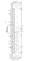
図1ないし図3において、1は連続炊飯機(連続式IH炊飯機)で、この連続炊飯機1は、炊飯釜2を搬送部3で略水平の搬送方向Xに間欠的に移動させながら加熱部4で加熱して、連続炊飯作業を行うものである。
1 to 3, 1 is a continuous rice cooker (continuous IH rice cooker), and this continuous rice cooker 1 is heated while moving the
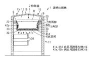
なお、炊飯釜2は、略矩形状の上面開口を有する外形略直方体状のもので、略矩形平板状の底面部6を有している。底面部6の外周端部には湾曲状(R状)の角部5が一体に設けられ、この角部5から急斜面状の側面部7が外斜め上方に向って突出し、この側面部7の上周端部が上面開口縁部8となっている。上面開口縁部8の搬送方向X両側からは取手部9が外側方に向って突出している。そして、底面部6と側面部7との間に湾曲状の角部5を有する炊飯釜2の上面開口は、炊飯作業時には蓋(図示せず)にて開閉可能に閉鎖される。
The
連続炊飯機1は、搬送方向Xに長手状で中空状の機枠11を備えている。機枠11には、加熱室(釜搬送路)12、釜入口13および釜出口14がそれぞれ形成されている。そして、機枠11の内側に形成された加熱室12の上方部は、取手15が付いた開閉可能な天蓋16にて覆われている。また、加熱室12の一端に連通した釜入口13は機枠11の長手方向一端部で常時開口し、加熱室12の他端に連通した釜出口14は機枠11の長手方向他端部で常時開口している。
The continuous rice cooker 1 includes a
また、機枠11には、駆動手段である駆動モータ21からの動力に基づいて回転する複数の回転体であるスプロケット22が回転可能に設けられている。そして、スプロケット22には、炊飯釜2を両側の取手部9を介して支持した状態で略水平の搬送方向Xに移動させる搬送用無端体であるチェーン23が巻き掛けられている。なお、駆動モータ21、スプロケット22およびチェーン23にて、炊飯釜2を搬送方向Xに搬送するチェーンコンベヤ式の搬送部3が構成されている。
In addition, the
また一方、機枠11は、搬送方向Xに長手状で縦断面略U字状のコイル支持部31を内側に有し、このコイル支持部31に搬送方向Xに移動中の炊飯釜2を加熱する加熱部4が加熱室12に臨んだ状態に設けられている。なお、コイル支持部31は、搬送方向Xに細長い略矩形板状をなす水平状の底板部32と、この底板部32の長手方向に沿った両側端部から上方に向って突出した側板部33とにて構成されている。
On the other hand, the
そして、コイル支持部31にて支持された加熱部4は、機枠11の内側において搬送方向X上流側に位置する高周波誘導加熱式つまりいわゆるIH式の炊飯加熱部(第1加熱部)36と、機枠11の内側において搬送方向X下流側に位置するIH式の蒸らし加熱部(第2加熱部)37とを具備している。
The
なお、炊飯加熱部36は、沸騰付近までの加熱処理を行うものであり、蒸らし加熱部37は、沸騰付近以降で加熱処理を行うものである。
In addition, the rice
ここで、炊飯加熱部36は、炊飯釜2の底面部6を加熱する複数(例えば搬送方向Xに沿った前後方向に複数、例えば4つ並び、かつ、搬送方向Xと直交する方向である左右方向に複数、例えば4つ並んだ、合計16)の略矩形板状の底面用誘導加熱コイルである第1底面用コイル41a,41b,41c,41dを備えている。
Here, the rice
これら第1底面用コイル41a,41b,41c,41dは、機枠11のコイル支持部31の底板部32の上面側に搬送方向Xに対して複数列状、例えば4列状に設けられている。そして、第1底面用コイル41a,41b,41c,41dは、加熱室12内を搬送方向Xに移動中の炊飯釜2の底面部6と所定間隔を介して対向するように、コイル支持部31の底板部32にて水平状に支持されている。
These first
なお、第1底面用コイル41aは底板部32の短辺方向一端部(搬送方向左端部)上に配置され、第1底面用コイル41dは底板部32の短辺方向他端部(搬送方向右端部)上に配置され、第1底面用コイル41b,41cは底板部32の短辺方向中央部(搬送方向中央部)上に配置されている(図1参照)。
The first
また、炊飯加熱部36は、互いに離間対向して配置され炊飯釜2の搬送方向X両側(搬送方向Xに対して左右両側)の側面部7を加熱する対(例えば左右4対で、合計8つ)をなす略矩形板状の側面用誘導加熱コイルである第1側面用コイル42a,42bを備えている。
Moreover, the rice
搬送方向X一方側である左側(図3中、上側)で前後方向に並んだ4つの第1側面用コイル42aは、機枠11のコイル支持部31の搬送方向X左側の側板部33の内面側に搬送方向Xに対して1列状に設けられている。そして、搬送方向X左側の第1側面用コイル42aは、加熱室12内を搬送方向Xに移動中の炊飯釜2の搬送方向X左側の側面部7と所定間隔を介して対向するように、コイル支持部31の搬送方向X左側の側板部33にて傾斜状に支持されている。
Four first
一方、搬送方向X他方側である右側(図3中、下側)で前後方向に並んだ4つの第1側面用コイル42bは、機枠11のコイル支持部31の搬送方向X右側の側板部33の内面側に搬送方向Xに対して1列状に設けられている。そして、搬送方向X右側の第1側面用コイル42bは、加熱室12内を搬送方向Xに移動中の炊飯釜2の搬送方向X右側の側面部7と所定間隔を介して対向するように、コイル支持部31の搬送方向X右側の側板部33にて傾斜状に支持されている。
On the other hand, the four
そして、第1底面用コイル41a,41b,41c,41dは、平面視で対をなす第1側面用コイル42a,42b間に位置するように配置されている。すなわち、互いに隣接して左右方向に並んだ第1底面用コイル41a,41b,41c,41dは、前後方向の位置(搬送方向Xの位置)が略等しい左右対をなす第1側面用コイル42a,42b間に平面視で位置するように配置されている。
The first
なお、第1底面用コイル41a,41b,41c,41dの外形寸法は炊飯釜2の搬送方向Xと直交する幅寸法では4つ並べることで底面部6略全体と対向できるようにし、第1側面用コイル42a,42bの外形寸法は炊飯釜2の高さ寸法では炊飯釜2内に入っている被加熱材料の高さと同じ程度となる側面部7と対向できるようにしている。また、各コイル41a,41b,41c,41d,42a,42bは、その長辺方向が搬送方向Xに一致した状態で配置されている。さらに、コイル41a,41b,41c,41d,42a,42bの搬送方向Xの長さ寸法は、1個の炊飯釜2の搬送方向Xの長さ寸法と略同じである。なお、後述の蒸らし加熱部37のコイルについても同様である。
The
また、第1底面用コイル41b,41cの加熱力と、第1底面用コイル41dおよび第1側面用コイル42bの加熱力と、第1底面用コイル41aおよび第1側面用コイル42aの加熱力とは、それぞれ個別に調節可能となっている。
Further, the heating power of the first bottom surface coils 41b and 41c, the heating power of the first
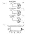
すなわち、図3に示されるように、搬送方向X最上流の2つのコイル41b,41cには両コイル41b,41cに電力を供給する第1インバータ401が接続され、搬送方向X最上流の2つのコイル41d,42bには両コイル41d,42bに電力を供給する第2インバータ402が接続され、搬送方向X最上流の2つのコイル41a,42aには両コイル41a,42aに電力を供給する第3インバータ403が接続され、以下同様にして第4ないし第12インバータ403,404,…,4012が接続されている。
That is, as shown in FIG. 3, the conveying direction X most upstream of the two
このように、搬送方向X上流側の炊飯加熱部36では、幅方向中央側のコイル41b,41cと幅方向一方側のコイル41a,42aと幅方向他方側のコイル41d,42bとには別々のインバータ401,402,…,4012が接続され、この個々のインバータ401,402,…,4012のインバータ出力の変更により同一のインバータに接続されたコイル群ごとの加熱力をそれぞれ個別に調節できるようになっている。すなわち、炊飯加熱部36が搬送方向Xに並んだ複数、例えば4つのゾーンにて構成されているとした場合、各ゾーンにおいて、コイル41b,41cの加熱力とコイル41a,42aの加熱力とコイル41d,42bの加熱力とがそれぞれ個別に調節可能となっている。
Thus, in the rice
また、炊飯釜2の搬送方向Xにおいても、炊飯釜2が間欠的に移動していく各地点(ゾーン)で、第1底面用コイルの加熱力および第1側面用コイルの加熱力は、個々のインバータとの接続によりそれぞれ個別に調節できるようになっている。すなわち、炊飯釜2の搬送方向Xに沿った複数の第1底面用コイルの加熱力はそれぞれ個別に調節可能でありかつ炊飯釜2の搬送方向Xに沿った複数の第1側面用コイルの加熱力はそれぞれ個別に調節可能である。なお、後述の蒸らし加熱部37のコイルについても同様である。
Moreover, also in the conveyance direction X of the
一方、蒸らし加熱部37は、炊飯釜2の底面部6を加熱する複数(例えば搬送方向Xに沿った前後方向に複数、例えば4つ並び、かつ、搬送方向Xと直交する方向である左右方向に複数、例えば4つ並んだ、合計16)の略矩形板状の底面用誘導加熱コイルである第2底面用コイル51a,51b,51c,51dを備えている。
On the other hand, the steaming
これら第2底面用コイル51a,51b,51c,51dは、機枠11のコイル支持部31の底板部32の上面側に搬送方向Xに対して複数列状、例えば4列状に設けられている。そして、第2底面用コイル51a,51b,51c,51dは、加熱室12内を搬送方向Xに移動中の炊飯釜2の底面部6と所定間隔を介して対向するように、コイル支持部31の底板部32にて水平状に支持されている。
These second
なお、第2底面用コイル51aは底板部32の短辺方向一端部(搬送方向左端部)上に配置され、第2底面用コイル51dは底板部32の短辺方向他端部(搬送方向右端部)上に配置され、第2底面用コイル51b,51cは底板部32の短辺方向中央部(搬送方向中央部)上に配置されている。
The second
また、蒸らし加熱部37は、互いに離間対向して配置され炊飯釜2の搬送方向X両側(搬送方向Xに対して左右両側)の側面部7を加熱する対(例えば左右4対で、合計8つ)をなす略矩形板状の側面用誘導加熱コイルである第2側面用コイル52a,52bを備えている。
In addition, the steaming
搬送方向X一方側である左側(図3中、上側)で前後方向に並んだ4つの第2側面用コイル52aは、機枠11のコイル支持部31の搬送方向X左側の側板部33の内面側に搬送方向Xに対して1列状に設けられている。そして、搬送方向X左側の第2側面用コイル52aは、加熱室12内を搬送方向Xに移動中の炊飯釜2の搬送方向X左側の側面部7と所定間隔を介して対向するように、コイル支持部31の搬送方向X左側の側板部33にて傾斜状に支持されている。
Four second side surface coils 52a arranged in the front-rear direction on the left side (upper side in FIG. 3) which is one side in the conveyance direction X are the inner surfaces of the
一方、搬送方向X他方側である右側(図3中、下側)で前後方向に並んだ4つの第2側面用コイル52bは、機枠11のコイル支持部31の搬送方向X右側の側板部33の内面側に搬送方向Xに対して1列状に設けられている。そして、搬送方向X右側の第2側面用コイル52bは、加熱室12内を搬送方向Xに移動中の炊飯釜2の搬送方向X右側の側面部7と所定間隔を介して対向するように、コイル支持部31の搬送方向X右側の側板部33にて傾斜状に支持されている。
On the other hand, the four second side coils 52b arranged in the front-rear direction on the right side (lower side in FIG. 3) which is the other side in the conveyance direction X are side plates on the right side in the conveyance direction X of the
そして、第2底面用コイル51a,51b,51c,51dは、平面視で対をなす第2側面用コイル52a,52b間に位置するように配置されている。すなわち、互いに隣接して左右方向に並んだ第2底面用コイル51a,51b,51c,51dは、前後方向の位置(搬送方向Xの位置)からの距離が略等しい左右対をなす第2側面用コイル52a,52b間に平面視で位置するように配置されている。
The second
なお、図3に示されるように、搬送方向X最上流から5番目の6つのコイル51a,51b,51c,51d,52a,52bには、それらコイル51a,51b,51c,51d,52a,52bに電力を供給する第13インバータ4013が接続され、以下同様にして第14ないし第16インバータ4014,4015,4016が接続されている。このため、搬送方向X下流側の蒸らし加熱部37では、炊飯加熱部36とは異なり、蒸らし加熱部37を構成する各ゾーンにおける底面部6への加熱力と側面部7への加熱力とをそれぞれ個別に調節はできなくなっている。しかし、炊飯釜2の搬送方向Xにおいて、炊飯釜2が間欠的に移動していく各地点(ゾーン)で、第2底面用コイルの加熱力および第2側面用コイルの加熱力は、個々のインバータとの接続によりそれぞれ個別に調節できるようになっている。
As shown in FIG. 3, the
また、複数(例えば16)のインバータ401,402,…,4016には、各インバータ401,402,…,4016に制御信号を出力して各インバータ401,402,…,4016を制御する集中制御部である1つの制御手段(制御盤)55が接続されている。そして、制御手段55は、各インバータ401,402,…,4016のインバータ出力を炊飯対象物の種類(例えば白飯、チキンライス、五目ご飯)に対応した値に設定する設定部56を有している。
The inverter 40 1, 40 2 of a plurality (e.g. 16), ..., the 40 16, the inverters 40 1, 40 2, ..., 40 16 the inverters 40 outputs a control signal to the 1, 40 2, ... , one control unit (control panel) 55 is connected, a centralized control unit which controls the 40 16. The control means 55 has a
なお、各インバータ401,402,…,4016は、機枠11のインバータ収容部39内に収容されている。
Each of the inverters 40 1 , 40 2 ,..., 40 16 is accommodated in the
さらに、図4(a)および(b)に示されるように、炊飯加熱部36の各ゾーンにおいて、搬送方向X左側の第1側面用コイル42aは、第1底面用コイル41aと所定間隔を介して離間対向して位置し、その第1底面用コイル41aと直列に接続されている。そして、第1底面用コイル41aの第1側面用コイル42aとの対向部分(外側端部)、および、第1側面用コイル42aの第1底面用コイル41aの対向部分(下端部)には、炊飯釜2の搬送方向X左側の角部5が所望の加熱力で加熱されるよう同じ方向の電流が流れるようになっている。これらコイル41a,42aの互いに隣接した対向部分に同じ方向の電流が流れると、両コイル41a,42a間の磁界の強さが強まり、湾曲状の角部5が所望の加熱力で加熱される。
Further, as shown in FIGS. 4A and 4B, in each zone of the
また同様に、炊飯加熱部36の各ゾーンにおいて、搬送方向X右側の第1側面用コイル42bは、第1底面用コイル41dと所定間隔を介して離間対向して位置し、その第1底面用コイル41dと直列に接続されている。そして、第1底面用コイル41dの第1側面用コイル42bとの対向部分(外側端部)、および、第1側面用コイル42bの第1底面用コイル41dの対向部分(下端部)には、炊飯釜2の搬送方向X右側の角部5が所望の加熱力で加熱されるよう同じ方向の電流が流れるようになっている。これらコイル41d,42bの互いに隣接した対向部分に同じ方向の電流が流れると、両コイル41d,42b間の磁界の強さが強まり、湾曲状の角部5が所望の加熱力で加熱される。
Similarly, in each zone of the rice
なお、炊飯加熱部36の各ゾーンにおいて、所定間隔を介して互いに離間対向した第1底面用コイル41b,41cは直列に接続され、互いに隣接した対向部分には同じ方向の電流が流れるようになっている。また、搬送方向Xの位置が略等しい6つのコイル41a,41b,41c,41d,42a,42bは、1個の炊飯釜2に対して底面部6、搬送方向X両側の側面部7、および、搬送方向X両側の角部5を同時に加熱するようになっている。
In each zone of the rice
また、図5(a)および(b)に示されるように、蒸らし加熱部37の各ゾーンにおいて、所定間隔を介して互いに離間対向したコイル51a,51b,51c,51d,52a,52bは直列に接続され、互いに隣接した対向部分には同じ方向の電流が流れるようになっている。また、搬送方向Xの位置が略等しい6つのコイル51a,51b,51c,51d,52a,52bは、1個の炊飯釜2に対して底面部6、搬送方向X両側の側面部7、および、搬送方向X両側の角部5を同時に加熱するようになっている。
Further, as shown in FIGS. 5A and 5B, in each zone of the
次に、上記連続炊飯機1の動作を説明する。 Next, the operation of the continuous rice cooker 1 will be described.
例えば白飯を炊飯する場合は、米および水を入れて蓋をした炊飯釜2を釜入口13から加熱室12内に供給し、その炊飯釜2を搬送部3で搬送方向Xに間欠的に移動させる。
For example, when cooking white rice,
炊飯釜2は、炊飯加熱部36のコイル41a,41b,41c,41d,42a,42bにて加熱されて炊飯加熱処理(沸騰付近までの加熱処理)され、その後、蒸らし加熱部37のコイル51a,51b,51c,51d,52a,52bにて加熱されて蒸らし加熱処理(沸騰付近以降での加熱処理)される。
The
このとき、制御手段55は、設定部56にて設定された条件つまり白飯用の加熱条件に応じた制御信号を各インバータ401,402,…,4016に出力し、各インバータ401,402,…,4016は、その制御信号に基づき、予め決められた値のインバータ出力を出力して、対応するコイルに電力を供給する。その結果、コイルには高周波電流(例えば周波数20kHz)が断続的に流れ、コイル周囲の磁力線が変化し、この磁力線の変化によって底面部6、搬送方向X両側の側面部7および搬送方向X両側の角部5に渦電流が発生して、各部分5,6,7が所望の加熱力で加熱される。
At this time, the
なお、蒸らし加熱処理後の炊飯釜2は、釜出口14から加熱室12外に排出され、次工程へ搬送されていく。
In addition, the
また、例えばチキンライスを炊飯する場合は、米、水、鶏肉、調味料等を入れて蓋をした炊飯釜2を釜入口13から加熱室12内に供給し、その炊飯釜2を搬送部3で搬送方向Xに間欠的に移動させる。
For example, when cooking rice with chicken rice,
すると、前記白飯の場合と同様に、炊飯釜2は、炊飯加熱部36の加熱により炊飯加熱処理され、その後、蒸らし加熱部37の加熱により蒸らし加熱処理されて次工程へ搬送されるが、制御手段55は、設定部56にて設定された条件つまりチキンライス用の加熱条件に応じた制御信号を各インバータ401,402,…,4016に出力するため、各インバータ401,402,…,4016は、予め決められた値のインバータ出力を対応するコイルへ出力することとなる。
Then, as in the case of the white rice, the
また、例えば五目ご飯を炊飯する場合は、米、水、調味料等を入れて蓋をした炊飯釜2を釜入口13から加熱室12内に供給し、その炊飯釜2を搬送部3で搬送方向Xに間欠的に移動させる。
In addition, for example, when cooking gomoku rice,
すると、前記白飯の場合と同様に、炊飯釜2は、炊飯加熱部36の加熱により炊飯加熱処理され、その後、蒸らし加熱部37の加熱により蒸らし加熱処理されて次工程へ搬送されるが、制御手段55は、設定部56にて設定された条件つまり五目ご飯用の加熱条件に応じた制御信号を各インバータ401,402,…,4016に出力するため、各インバータ401,402,…,4016は、予め決められた値のインバータ出力を対応するコイルへ出力することとなる。
Then, as in the case of the white rice, the
そして、上記連続炊飯機1によれば、第1底面用コイル41aおよび第1側面用コイル42aのうち互いに隣接した対向部分に同じ方向の電流を流しかつ第1底面用コイル41dおよび第1側面用コイル42bのうち互いに隣接した対向部分に同じ方向の電流を流すことにより、コイル41a,41d,42a,42bからの距離が遠くなる搬送方向X両側の湾曲状の角部5であっても、他の平板状の部分と同じように所望の加熱力で加熱できるため、適切な連続炊飯作業ができる。よって、釜内全体を均等に炊き上げることができ、白飯等の炊飯対象物をおいしく仕上げることができる。
And according to the said continuous rice cooker 1, the electric current of the same direction is sent through the opposing part which mutually adjoined among the
また、従来のIH式の連続炊飯機とは異なり、例えば炊飯対象物の種類に対応して、IH式の炊飯加熱部36の幅方向中央側のコイル41b,41cの加熱力と幅方向一方側のコイル41a,42aの加熱力と幅方向他方側のコイル41d,42bの加熱力とをそれぞれ個別に調節できるとともに、搬送方向Xに並んだ複数の底面用コイルの加熱力をそれぞれ個別に調節できかつ搬送方向Xに並んだ複数の側面用コイルの加熱力をそれぞれ個別に調節できるため、より一層適切な連続炊飯作業ができ、例えば白飯だけでなく、チキンライスや五目ご飯も、焦がさず、おいしく炊き上げることができる。
Also, unlike the conventional IH type continuous rice cooker, for example, corresponding to the type of rice cooking object, the heating power of the
なお、炊飯加熱部36のみにおいて、第1底面用コイル41aと第1側面用コイル42a、および、第1底面用コイル41dと第1側面用コイル42bをそれらコイル間で磁界が強まるように接続した構成には限定されず、蒸らし加熱部37において、第2底面用コイル51aと第2側面用コイル52a、および、第2底面用コイル51dと第2側面用コイル52bをそれらコイル間で磁界が強まるように接続した構成としてもよい。
Incidentally, only in 炊
さらに、炊飯加熱部36に加えて蒸らし加熱部37においてもコイルの加熱力を個別に調節できるようにしてもよい。
Further, the heating power of the coils may be individually adjusted in the
1 連続炊飯機
2 炊飯釜
5 角部
6 底面部
7 側面部
402,403,405,406,408,409,4011,4012 インバータ
41a,41b,41c,41d 底面用誘導加熱コイルである第1底面用コイル
42a,42b 側面用誘導加熱コイルである第1側面用コイル
X 搬送方向
DESCRIPTION OF SYMBOLS 1
40 2 , 40 3 , 40 5 , 40 6 , 40 8 , 40 9 , 40 11 , 40 12 Inverter
41a, 41b, 41c, 41d First bottom surface coil that is an induction heating coil for the bottom surface
42a, 42b Inductive heating coil for side 1st side coil X Conveying direction
Claims (2)
搬送方向の長さ寸法が炊飯釜の搬送方向の長さ寸法と略同じであり、搬送方向と直交する左右方向に複数並設されて炊飯釜の底面部の略全体と対向し、炊飯釜の底面部を加熱する底面用誘導加熱コイルと、
搬送方向の長さ寸法が炊飯釜の搬送方向の長さ寸法と略同じであり、搬送方向と直交する左右方向の両端部に位置する底面用誘導加熱コイルに隣接して対向するとともにこの底面用誘導加熱コイルと直列に接続され、炊飯釜の側面部のうち被加熱材料が入っている高さ程度までの部分と対向し、炊飯釜の側面部を加熱する側面用誘導加熱コイルとを備え、
互いに隣接する底面用誘導加熱コイルおよび側面用誘導加熱コイルは、同一のインバータに接続され、
炊飯釜は、底面部と側面部との間に湾曲状の角部を有し、
搬送方向と直交する左右方向の両端部に位置する底面用誘導加熱コイルの側面用誘導加熱コイルとの対向部分および側面用誘導加熱コイルの底面用誘導加熱コイルとの対向部分には、同じ方向の電流を流して、各コイルとの間隔が所定間隔より大きい炊飯釜の角部が、互いに隣接する底面用誘導加熱コイルおよび側面用誘導加熱コイルの各対向部分からの所望の加熱力で加熱される
ことを特徴とする連続炊飯機。 A substantially rectangular plate that is heated while intermittently moving a rice cooker having a substantially rectangular parallelepiped shape in the conveyance direction, and that is arranged in plural along the conveyance direction of the rice cooker and faces the bottom portion of the rice cooker via a predetermined interval. A substantially rectangular plate-shaped induction heating coil for a bottom surface and a substantially rectangular plate-shaped induction heating coil for a side surface that are arranged along a conveying direction of the rice cooking pot and are opposed to each other at a predetermined interval. A continuous rice cooker to be arranged ,
The length dimension in the conveying direction is substantially the same as the length dimension in the conveying direction of the rice cooker, a plurality of juxtaposed in the left-right direction perpendicular to the conveying direction is opposed to substantially the entire bottom of the rice cooking pot, An induction heating coil for the bottom surface for heating the bottom surface portion;
The length dimension in the conveying direction is substantially the same as the length dimension in the conveying direction of the rice cooker, and it is adjacent to and opposed to the bottom induction heating coils located at both ends in the left-right direction orthogonal to the conveying direction. It is connected in series with the induction heating coil, is opposed to a portion up to the height of the side portion of the rice cooker containing the material to be heated , and includes a side induction heating coil for heating the side portion of the rice cooker,
The bottom side induction heating coil and the side induction heating coil adjacent to each other are connected to the same inverter,
The rice cooker has a curved corner between the bottom part and the side part,
In the opposite direction of the induction heating coil for the bottom surface and the opposite side of the induction heating coil for the side surface of the induction heating coil for the side surface located at both ends in the left-right direction orthogonal to the conveyance direction, By passing an electric current, the corners of the rice cooker whose distance from each coil is larger than a predetermined distance are heated with a desired heating force from the opposing portions of the bottom surface induction heating coil and the side surface induction heating coil adjacent to each other. A continuous rice cooker characterized by that.
搬送方向においては、炊飯釜が間欠的に移動していく各ゾーンで、底面用誘導加熱コイルの加熱力および側面用誘導加熱コイルの加熱力を、個々のインバータとの接続によりそれぞれ個別に調節できるようになっている
ことを特徴とする請求項1記載の連続炊飯機。 Bottom-side induction heating coil located on the center side in the left-right direction orthogonal to the transport direction, bottom-side induction heating coil and side-side induction heating coil located on one side in the left-right direction, and bottom-side induction heating coil located on the other side in the left-right direction A separate inverter is connected to each of the coil and the side induction heating coil so that the heating power of each coil group connected to the same inverter can be adjusted individually by changing the inverter output of this individual inverter. And
In the conveyance direction, the heating power of the induction heating coil for the bottom surface and the heating power of the induction heating coil for the side surface can be individually adjusted by connecting to each inverter in each zone where the rice cooker moves intermittently. The continuous rice cooker according to claim 1, which is configured as described above.
Priority Applications (1)
| Application Number | Priority Date | Filing Date | Title |
|---|---|---|---|
| JP2003288619A JP4100684B2 (en) | 2003-08-07 | 2003-08-07 | Continuous rice cooker |
Applications Claiming Priority (1)
| Application Number | Priority Date | Filing Date | Title |
|---|---|---|---|
| JP2003288619A JP4100684B2 (en) | 2003-08-07 | 2003-08-07 | Continuous rice cooker |
Publications (2)
| Publication Number | Publication Date |
|---|---|
| JP2005052529A JP2005052529A (en) | 2005-03-03 |
| JP4100684B2 true JP4100684B2 (en) | 2008-06-11 |
Family
ID=34367219
Family Applications (1)
| Application Number | Title | Priority Date | Filing Date |
|---|---|---|---|
| JP2003288619A Expired - Fee Related JP4100684B2 (en) | 2003-08-07 | 2003-08-07 | Continuous rice cooker |
Country Status (1)
| Country | Link |
|---|---|
| JP (1) | JP4100684B2 (en) |
Cited By (1)
| Publication number | Priority date | Publication date | Assignee | Title |
|---|---|---|---|---|
| IT202000030416A1 (en) | 2020-12-10 | 2022-06-10 | A M T S R L | "KETTLES WITH ENERGY RECOVERY" |
Families Citing this family (1)
| Publication number | Priority date | Publication date | Assignee | Title |
|---|---|---|---|---|
| JP4962897B2 (en) * | 2005-09-22 | 2012-06-27 | 株式会社サタケ | Induction heating rice cooking unit |
-
2003
- 2003-08-07 JP JP2003288619A patent/JP4100684B2/en not_active Expired - Fee Related
Cited By (1)
| Publication number | Priority date | Publication date | Assignee | Title |
|---|---|---|---|---|
| IT202000030416A1 (en) | 2020-12-10 | 2022-06-10 | A M T S R L | "KETTLES WITH ENERGY RECOVERY" |
Also Published As
| Publication number | Publication date |
|---|---|
| JP2005052529A (en) | 2005-03-03 |
Similar Documents
| Publication | Publication Date | Title |
|---|---|---|
| US8919245B2 (en) | Induction cooking structure and system and method of using the same | |
| EP3634087B1 (en) | Electromagnetic induction heating cooker | |
| JP5322831B2 (en) | Induction heating cooker | |
| KR102190517B1 (en) | Apparatus for manufacturing scorching rice | |
| JP4100684B2 (en) | Continuous rice cooker | |
| WO2016181208A1 (en) | Induction cooking apparatus and method of controlling induction cooking apparatus | |
| JP4100682B2 (en) | Continuous rice cooker | |
| JP4100683B2 (en) | Continuous rice cooker | |
| SE0300133D0 (en) | A barbecue grill and a grill for grilling food | |
| CN205433292U (en) | Be suitable for electromagnetic heating's interior pot, bread machine and cooking utensil | |
| TW201815225A (en) | Heating cooking appliance | |
| WO2019176110A1 (en) | Induction heating cooker | |
| JP4318362B2 (en) | Induction heating device | |
| JP6757554B2 (en) | Continuous rice cooker | |
| JP5697234B2 (en) | Rice cooker | |
| JP6964155B2 (en) | Cooker | |
| JP7336642B2 (en) | heating cooker | |
| JP7300591B2 (en) | Heating coil unit and heating cooker | |
| JP6730081B2 (en) | Continuous rice cooker | |
| CN205433291U (en) | Cooking utensil | |
| JP5751712B2 (en) | Electromagnetic cooker, electromagnetic induction device and metal heating medium used therefor | |
| JP6944585B2 (en) | Continuous rice cooker | |
| JPH114770A (en) | Heating device for food | |
| JP2001161549A (en) | rice cooker | |
| KR100266547B1 (en) | An electric heating plate of oven |
Legal Events
| Date | Code | Title | Description |
|---|---|---|---|
| A621 | Written request for application examination |
Free format text: JAPANESE INTERMEDIATE CODE: A621 Effective date: 20060426 |
|
| A977 | Report on retrieval |
Free format text: JAPANESE INTERMEDIATE CODE: A971007 Effective date: 20071026 |
|
| A131 | Notification of reasons for refusal |
Free format text: JAPANESE INTERMEDIATE CODE: A131 Effective date: 20071031 |
|
| A521 | Request for written amendment filed |
Free format text: JAPANESE INTERMEDIATE CODE: A523 Effective date: 20071217 |
|
| TRDD | Decision of grant or rejection written | ||
| A01 | Written decision to grant a patent or to grant a registration (utility model) |
Free format text: JAPANESE INTERMEDIATE CODE: A01 Effective date: 20080312 |
|
| A61 | First payment of annual fees (during grant procedure) |
Free format text: JAPANESE INTERMEDIATE CODE: A61 Effective date: 20080317 |
|
| FPAY | Renewal fee payment (event date is renewal date of database) |
Free format text: PAYMENT UNTIL: 20110328 Year of fee payment: 3 |
|
| R150 | Certificate of patent or registration of utility model |
Ref document number: 4100684 Country of ref document: JP Free format text: JAPANESE INTERMEDIATE CODE: R150 Free format text: JAPANESE INTERMEDIATE CODE: R150 |
|
| FPAY | Renewal fee payment (event date is renewal date of database) |
Free format text: PAYMENT UNTIL: 20140328 Year of fee payment: 6 |
|
| R250 | Receipt of annual fees |
Free format text: JAPANESE INTERMEDIATE CODE: R250 |
|
| R250 | Receipt of annual fees |
Free format text: JAPANESE INTERMEDIATE CODE: R250 |
|
| R250 | Receipt of annual fees |
Free format text: JAPANESE INTERMEDIATE CODE: R250 |
|
| LAPS | Cancellation because of no payment of annual fees | ||
| RD02 | Notification of acceptance of power of attorney |
Free format text: JAPANESE INTERMEDIATE CODE: R3D02 |