JP4098089B2 - Fixed element - Google Patents
Fixed element Download PDFInfo
- Publication number
- JP4098089B2 JP4098089B2 JP2002574833A JP2002574833A JP4098089B2 JP 4098089 B2 JP4098089 B2 JP 4098089B2 JP 2002574833 A JP2002574833 A JP 2002574833A JP 2002574833 A JP2002574833 A JP 2002574833A JP 4098089 B2 JP4098089 B2 JP 4098089B2
- Authority
- JP
- Japan
- Prior art keywords
- head
- shank
- lumen
- element according
- fixing element
- Prior art date
- Legal status (The legal status is an assumption and is not a legal conclusion. Google has not performed a legal analysis and makes no representation as to the accuracy of the status listed.)
- Expired - Lifetime
Links
Images


Classifications
-
- A—HUMAN NECESSITIES
- A61—MEDICAL OR VETERINARY SCIENCE; HYGIENE
- A61B—DIAGNOSIS; SURGERY; IDENTIFICATION
- A61B17/00—Surgical instruments, devices or methods, e.g. tourniquets
- A61B17/56—Surgical instruments or methods for treatment of bones or joints; Devices specially adapted therefor
- A61B17/58—Surgical instruments or methods for treatment of bones or joints; Devices specially adapted therefor for osteosynthesis, e.g. bone plates, screws, setting implements or the like
- A61B17/68—Internal fixation devices, including fasteners and spinal fixators, even if a part thereof projects from the skin
- A61B17/70—Spinal positioners or stabilisers ; Bone stabilisers comprising fluid filler in an implant
- A61B17/7001—Screws or hooks combined with longitudinal elements which do not contact vertebrae
- A61B17/7035—Screws or hooks, wherein a rod-clamping part and a bone-anchoring part can pivot relative to each other
-
- A—HUMAN NECESSITIES
- A61—MEDICAL OR VETERINARY SCIENCE; HYGIENE
- A61B—DIAGNOSIS; SURGERY; IDENTIFICATION
- A61B17/00—Surgical instruments, devices or methods, e.g. tourniquets
- A61B17/56—Surgical instruments or methods for treatment of bones or joints; Devices specially adapted therefor
- A61B17/58—Surgical instruments or methods for treatment of bones or joints; Devices specially adapted therefor for osteosynthesis, e.g. bone plates, screws, setting implements or the like
- A61B17/68—Internal fixation devices, including fasteners and spinal fixators, even if a part thereof projects from the skin
- A61B17/70—Spinal positioners or stabilisers ; Bone stabilisers comprising fluid filler in an implant
- A61B17/7001—Screws or hooks combined with longitudinal elements which do not contact vertebrae
- A61B17/7032—Screws or hooks with U-shaped head or back through which longitudinal rods pass
-
- A—HUMAN NECESSITIES
- A61—MEDICAL OR VETERINARY SCIENCE; HYGIENE
- A61B—DIAGNOSIS; SURGERY; IDENTIFICATION
- A61B17/00—Surgical instruments, devices or methods, e.g. tourniquets
- A61B17/56—Surgical instruments or methods for treatment of bones or joints; Devices specially adapted therefor
- A61B17/58—Surgical instruments or methods for treatment of bones or joints; Devices specially adapted therefor for osteosynthesis, e.g. bone plates, screws, setting implements or the like
- A61B17/68—Internal fixation devices, including fasteners and spinal fixators, even if a part thereof projects from the skin
- A61B17/70—Spinal positioners or stabilisers ; Bone stabilisers comprising fluid filler in an implant
- A61B17/7001—Screws or hooks combined with longitudinal elements which do not contact vertebrae
- A61B17/7035—Screws or hooks, wherein a rod-clamping part and a bone-anchoring part can pivot relative to each other
- A61B17/7037—Screws or hooks, wherein a rod-clamping part and a bone-anchoring part can pivot relative to each other wherein pivoting is blocked when the rod is clamped
-
- A—HUMAN NECESSITIES
- A61—MEDICAL OR VETERINARY SCIENCE; HYGIENE
- A61B—DIAGNOSIS; SURGERY; IDENTIFICATION
- A61B17/00—Surgical instruments, devices or methods, e.g. tourniquets
- A61B17/56—Surgical instruments or methods for treatment of bones or joints; Devices specially adapted therefor
- A61B17/58—Surgical instruments or methods for treatment of bones or joints; Devices specially adapted therefor for osteosynthesis, e.g. bone plates, screws, setting implements or the like
- A61B17/68—Internal fixation devices, including fasteners and spinal fixators, even if a part thereof projects from the skin
- A61B17/84—Fasteners therefor or fasteners being internal fixation devices
- A61B17/86—Pins or screws or threaded wires; nuts therefor
- A61B17/8685—Pins or screws or threaded wires; nuts therefor comprising multiple separate parts
Description
【0001】
この発明は、ねじ部と、球の一部として形成された部分として設計された頭部とを含むねじを備え、さらに、特許請求項1の導入部に従い、このねじをロッドに接続するための受け部を備えた固定要素に関する。この種類の固定要素は、特に脊柱の手術で用いられるが、他の骨への事故手術でも用いられる。
【0002】
このような固定要素は、たとえばDE 43 07 576C1から公知である。この種類の公知の固定要素およびねじでは、ねじのねじ部とその頭部とが一体となって構成される。外科医はきわめてさまざまな長さのねじを必要とするため、さまざまな組のこのようなねじを、常に利用可能な状態にしておかなければならない。このことにより、かなりの在庫が必要となり、結果的にかなりのコストを生じる。
【0003】
この発明の目的は、このような欠点をなくすことである。
この目的は、特許請求項1に特徴付けられる固定要素によって達成される。その結果、外科医は、適用の間に、体内埋植の前または後に、ねじ部を所望の長さに短縮し、次に、それを頭部および受け部に接続することができる。このようにして在庫品のメンテナンスが実質的に減じられ、同時に、外科医がより微細な調整を行なうことを可能にする。なぜなら、ねじはどのような長さにも短縮することができるからである。
【0004】
この発明の発展は、従属請求項において特徴付けられる。
この発明のさらなる特性および適性は、図面の助けを得た実施例の説明から明らかである。
【0005】
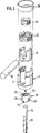
図1および図2に示される第1の実施例では、固定要素は、第1の端2および対向する第2の端3を備えた円筒構造の受け部1を含む。2つの端は対称軸または長手方向軸4に対して垂直に延びる。長手方向軸4と同軸に、第1の端2から延びて第2の端3から予め定められた距離まで延びる、第1の同軸内腔5が設けられる。第2の端3において、直径が第1の内腔の直径よりも小さい第2の内腔が設けられる。示される実施例において、第2の内腔は、中心が第1の端2に向けられる中空の球の一部として形成された部分としてその縁が形成される、開口として設計される。
【0006】
受け部1は、第1の端2から始まって長手方向軸4に対して垂直に延び、かつ第1の端2に向けて終端となる2つの自由アーム8および9を備えた、U字形の凹部7を含む。第1の端2に隣接して、アームは雌ねじ10を含む。U字形の凹部の底は第2の端3から予め定められた距離まで延びる。第1の端2に隣接して、アーム8および9はその外側に、外径が受け部の隣接部分の外径よりも小さい部分11を含む。
【0007】
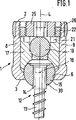
受け部1と協働するねじ12は、骨ねじとして設計されるねじ部13と、図1に示される組立図において、ねじ部に接続される、球の一部として形成された頭部15とを含む。頭部は、図1に示されるように、頭部15が第2の内腔6内で受けられる際に、頭部と、そこに形成された中空の球の一部として形成された壁の部分とが噛み合うような半径を有し、中空の球の一部として形成された部分は、球の中心16が第1の端2に向かって、その部分が当接部を形成し、球または頭部15が、第2の内腔6の中空の球の一部として形成された部分内に保持されるようにオフセットされて設計される。
【0008】
圧力要素17がさらに設けられ、これは円筒構造で大きな外径を有するために、それを第1の内腔5内に差込み、内腔5内で軸方向に往復して動かすことができる。圧力要素17は、第2の端3と面するその下側において、長手方向軸4に対して対称に構成されかつその半径が頭部5の半径に対応する中空の球の一部として形成される部分を含む。圧力要素は、長手方向軸4に対して横方向に延びかつその自由アームが第1の端2に向かって延びる、U字形の凹部18を含む。このU字形の凹部の横径は、受けるべきロッド19が凹部内に挿入されて凹部内で横方向に案内され得るよう選択される。中空の球の一部として形成された凹部の深さは、第1の端2に向かって、その凹部が、中心16から頭部15の半径に対応する距離よりも大きい、第2の端3からの或る距離で、終端となるよう選択される。U字形の凹部18の底には、受けるべきロッド19の直径より直径が小さい、隣接する同軸内腔20がある。
【0009】
図1から分かるように、U字形の凹部18は、第1の端2に向かう端において、内側幅がU字形の凹部18の直径よりも大きな部分21を含む。
【0010】
第1の端2に面する側では、圧力要素17が、雌ねじ10と噛み合う雄ねじ23に加え、雌ねじ24を含むナット22によって接合される。ナット22の内側寸法は、その内側幅が部分21の直径よりも小さくかつロッド19、従って、U字形の凹部18の直径よりも大きくなるよう選択される。さらに、雌ねじ24と噛み合う雄ねじを備えた内ナット25が設けられる。最後に、図1に示されるように、第1の端2に隣接する自由端を囲み、組立状態で環状部11の上にあるブシュ26が設けられる。
【0011】
図2から最もよく分かるように、ナット22はスロットを含み、内ナット25は、ねじ回しのそれぞれの個別の適用のために六角形の開口を含む。
【0012】
図2から最もよく分かるように、頭部15は、第1の端2に面すべき端が平らにされた球として設計され、長手方向軸4と同軸の内腔27を含む。内腔27の直径はシャンク14の外径と等しく、シャンクが摩擦締付けにより内腔内に挿入され得るよう設計される。図2から分かるように、このようにして形成された、中空の球の一部として形成された要素は、平らにされた端と反対の側に、円周方向に互いに離して置かれて長手方向軸4に対して平行に延び、かつ平らにされた側と反対の端まで延びる部分28および29を備える。その結果、第1の端2と反対面の縁30は、シャンク14を差込むためにばねで外側に撓むことができるよう設計される。
【0013】
動作の際には、まず、ねじ12が骨または椎骨にねじ込まれる。このために、シャンク14は、六角穴等の公知の係合の可能性を有する。次に、外科医はシャンク14を所望の長さにまで短縮し、まず、第2の内腔を備えた受け部をシャンク14上に置き、次に、頭部を第1の端2からシャンク14上に案内してシャンク14をばねで撓む縁30から内腔27内に差込み、図1に示される態様で頭部がシャンクを取囲む。頭部15とシャンク14とは摩擦締付けによって互いに接続される。次に、圧力要素17が挿入され、ナット22を締付けることにより、頭部15が所望の回転安定性を得るよう、頭部15上に押付けられる。ブシュ26がはめ合わされ、次に、内ナット25によってロッド19が固定される。ロッド19は圧力要素17を介し、頭部15上にさらなる圧力を加える。
【0014】
第1の端2から見て加えられた、頭部15への圧力により、スロットを付けられた頭部15はシャンク14に接続またはクランプされて動きが防がれる一方で、同時に、頭部はその回転位置に固定される。
【0015】
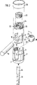
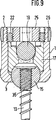
図3に示される第2の実施例は、上述の実施例とは、変形された頭部31が異なる。変形された頭部は、第1の実施例のように、互いに円周方向にオフセットされて第1の端と反対面の縁34において自由端をなし、かつ第1の端2と対面する縁32から或る距離にある、切欠き28を含む。しかしながら、縁32から反対の縁34まで完全に延びる切欠き33が設けられ、その結果、このようにして形成された球の一部は、切欠き33の幅によって規定される圧力量によって圧縮され得る。このようにして形成されるスロット33の幅は、まず、第2の端3から第1の内腔5内に、図3に示される方向に頭部31を押込むことができるよう頭部31を圧縮することができ、次に、シャンク14を上述の方法と同じように頭部内に挿入することができ、同様にクランプされた位置に保持するよう、選択される。
【0016】
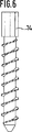
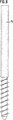
ねじのシャンク14は、好ましくは、図4または図5に示される円筒形状を有するか、図6および図7に示される多角形の形状を有する。図6および図7において、断面は八角形である。さらなる好ましい実施例が図8に示される。シャンクはここで円筒状であり、球15とシャンクとの間の係合を容易にする粗面を含む。
【0017】
図9に示されるさらなる実施例は、受け部1、圧力要素17、ロッド19、ならびにねじ22および25に関するすべての特性において先行の実施例に対応する。唯一の違いは、頭部15が、その外径においては2つの先行の球の一部に対応するが切欠き28または33を有さない球の一部として設計されることにある。代わりに、球の一部はその内腔27の内側に雌ねじを有する。シャンク14の代わりに、頭部の雌ねじと噛み合うよう設計されるねじ山を備えたシャンク35がもたらされる。内腔は、自由端2に対面する端において終端をなすか、そこに止め部を有する、止まり内腔(blind bore)として設計され、球の一部の平らにされた側からねじが突出しない、示された位置までしかねじを締付けることができない。図9が示すように、頭部15の雌ねじと、シャンク35の対応する雄ねじとは、好ましくは、骨ねじのねじ部13のねじ山の方向とは反対の方向に形成される。
【0018】
動作は、最初に述べた実施例と同じ態様で行なわれ、シャンク35を短縮した後、頭部15が受け部1の第1の端2から内腔5内に差込まれ、第2の端3から差込まれたシャンク35上にねじ締めされる。
【0019】
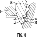
図10および図11に示されるさらなる実施例は、受け部1、圧力要素17、ロッド19、ならびにねじ22および25に関するすべての特性において先行の実施例に対応する。協働するねじ山を含む、図9に従った実施例のシャンク35および頭部15の代わりに、この実施例では、シャンク37は、骨ねじ部と反対の端に隣接する部分において波形を付けられたロッドとして設計される。シャンクの外表面は、円周方向に走る谷38と、それらの間の山39とを含む。谷38は、円周方向から見ると、円の一部として形成された断面を有し、上下中ほどまでのそれらの直径は、山39の対応する直径よりもはるかに大きく、山39は、谷38の底に対して鋭くなる。頭部15は、その外径においては上述の球の一部と対応するが切欠き28または33を有さない球の一部として設計される。頭部15の球の一部は、その内腔27の内側で、シャンク37の山39と谷38とにそれぞれ対応する谷40と山41とを備えた、円周方向に走る波形を含む。一方の、シャンクの谷38および山39と、他方の、対応する山40および谷41との間には小さな空隙があるので、シャンクを球の一部内に差込むことができる。
【0020】
動作は、図9に従った実施例と同様の態様で行なわれる。しかしながら、この実施例で波形の付けられたシャンク37を短縮することは、図9に従った、ねじ山を備えたシャンク35を短縮することよりも易しい。なぜなら、図9に従った、ねじ山を備えたシャンク35についてはねじ山が壊れないように注意を払う必要があるのに対し、谷38は切断が容易に行なえるためである。シャンク37を短縮した後、頭部15は受け部1の第1の端2から内腔5内に差込まれ、シャンク37上に押付けられる。このプロセスにおいて、シャンク37と、頭部15の内腔27の対応する波形とは協働してシャンクを保持する。
【0021】
上述の実施例では、いずれの場合も、頭部15は受け部1と一体となって設計された縁によって保持される。このような当接部を別の方法でも形成することができ、たとえば、受け部1を貫通して第1の内腔5をあけ、次に、その中に、第2の端に隣接して、頭部15を受ける保持要素を装着することができる。
【0022】
上述の実施例において、受け部は、ナット22および内ナット25に加え、ブシュ26を常に含む。この固定を、公知の態様で異なって設計することもできる。特に、状況によっては内ナットのみを設けることができる。
【0023】
図9を参照した上述の実施例では、頭部15は切欠き28、33を有さない。さらなる実施例では、頭部15とシャンク35とは、図9に示される図のように、互いに噛み合うねじ山を有する。しかしながら、頭部15は、全長にわたって延びる切欠き33をさらに含み、図3に示される実施例のように、シャンクがねじ込まれていない頭部を加圧によって縁3から受け部内に挿入し、次に、これもまた端3から差込むことのできるシャンク35上にねじ込むことによってはめ合いにし、シャンク35に接続することができる。スロットを設けた結果、圧力要素が適用されるか圧力が頭部15に加えられる際に、同時に、頭部およびシャンク35はこのようなスロットがないものに比べ、より強固に加圧される。
【0024】
さらなる実施例では、切欠き28を図3に示される態様でさらに設けることができ、したがって、ねじ切りされたシャンク35と一層大きな接触圧を生じることができる。
【図面の簡単な説明】
【図1】 第1の実施例の断面側面図である。
【図2】 図1で示された実施例の分解図である。
【図3】 第2の実施例の、対応する分解図である。
【図4】 両方の実施例で用いられる第1の骨ねじの側面図である。
【図5】 図4の骨ねじの上面図である。
【図6】 第1の2つの実施例で用いられる、骨ねじの第2の実施例の側面図である。
【図7】 図6に示される骨ねじの上面図である。
【図8】 第1の2つの実施例に示される骨ねじの、第3の実施例の側面図である。
【図9】 さらなる実施例の断面側面図である。
【図10】 さらなる実施例の断面側面図である。
【図11】 図10の細部Xの拡大図である。[0001]
The invention comprises a screw comprising a screw part and a head designed as a part formed as part of a sphere, and according to the introduction of claim 1 for connecting the screw to a rod The present invention relates to a fixing element having a receiving part. This type of fixation element is used in particular for spinal surgery, but also for accidental surgery on other bones.
[0002]
Such a fixing element is known from DE 43 07 576 C1, for example. In a known fixing element and screw of this type, the screw portion of the screw and its head are configured integrally. Since surgeons require very different lengths of screws, different sets of such screws must always be available. This requires significant inventory and results in significant costs.
[0003]
The object of the present invention is to eliminate such drawbacks.
This object is achieved by a fixing element characterized in claim 1. As a result, the surgeon can shorten the threaded portion to the desired length during application before or after implantation in the body, and then connect it to the head and receiving portion. In this way, inventory maintenance is substantially reduced while at the same time allowing the surgeon to make finer adjustments. This is because the screw can be shortened to any length.
[0004]
The development of the invention is characterized in the dependent claims.
Further characteristics and suitability of the invention will be apparent from the description of the embodiments with the aid of the drawings.
[0005]
In the first embodiment shown in FIGS. 1 and 2, the anchoring element comprises a cylindrical receiving part 1 with a
[0006]
The receiving part 1 is U-shaped with two
[0007]
The
[0008]
A
[0009]
As can be seen from FIG. 1, the U-shaped recess 18 includes a
[0010]
On the side facing the
[0011]
As best seen in FIG. 2,
[0012]
As best seen in FIG. 2, the
[0013]
In operation, the
[0014]
The slotted
[0015]
The second embodiment shown in FIG. 3 differs from the above-described embodiment in the modified
[0016]
The
[0017]
The further embodiment shown in FIG. 9 corresponds to the previous embodiment in all properties relating to the receptacle 1, the
[0018]
The operation is carried out in the same manner as in the first embodiment, after the
[0019]
The further embodiment shown in FIGS. 10 and 11 corresponds to the previous embodiment in all properties relating to the receiving part 1, the
[0020]
The operation is performed in a manner similar to the embodiment according to FIG. However, shortening the
[0021]
In any of the above embodiments, the
[0022]
In the embodiment described above, the receiving part always includes a
[0023]
In the embodiment described above with reference to FIG. 9, the
[0024]
In a further embodiment, a
[Brief description of the drawings]
FIG. 1 is a cross-sectional side view of a first embodiment.
FIG. 2 is an exploded view of the embodiment shown in FIG.
FIG. 3 is a corresponding exploded view of the second embodiment.
FIG. 4 is a side view of a first bone screw used in both examples.
FIG. 5 is a top view of the bone screw of FIG.
FIG. 6 is a side view of a second embodiment of a bone screw used in the first two embodiments.
7 is a top view of the bone screw shown in FIG. 6. FIG.
FIG. 8 is a side view of a third embodiment of the bone screw shown in the first two embodiments.
FIG. 9 is a cross-sectional side view of a further embodiment.
FIG. 10 is a cross-sectional side view of a further embodiment.
FIG. 11 is an enlarged view of detail X in FIG. 10;
Claims (9)
前記ねじ部(13)と前記頭部(15)とは個別の部分として設計され、さらに、前記頭部(15)は前記ねじ部(13)と対面する側に、ばねで撓む縁を含み、
前記頭部(15)は、前記第2の端(3)の方向から前記頭部に作用する圧力により前記シャンク(14)にクランプされるとともに、その回転位置が固定される、固定要素。A screw part (13), a head part (15) designed as a part formed as a part of a sphere, and a shank (14) provided on the head part (15) side of the screw part (13); A fixing element including a receiving part (1) for connecting the screw (12) to the rod (19), the receiving part (1) being a first element. The end (2) and the second end (3) opposite the first end, the longitudinal axis (4) passing through the first and second ends (2, 3), and the longitudinal axis A lumen (5) coaxial with (4) and two free arms (8, 9) adjacent to said first end (2) and containing threads for receiving a rod (19) to be inserted A first region having an essentially U-shaped cross-section (7) with a region adjacent to the other end (3) and for receiving said head (15) , And a component (22,17) to apply pressure on the rod (19) or on the head (15),
The screw part (13) and the head part (15) are designed as separate parts, and the head part (15) further includes a spring-curved edge on the side facing the screw part (13). ,
A fixing element, wherein the head (15) is clamped to the shank (14) by the pressure acting on the head from the direction of the second end (3) and its rotational position is fixed .
(37)はその外側に、対応する波形を含むことを特徴とする、請求項1から4のいずれか1つに記載の固定要素。It said head (15) is corrugated in the circumferential direction within the lumen, the shank (37) on its outer side, characterized in that it comprises a corresponding waveform, any one of claims 1 to 4, Fixed element as described in.
Applications Claiming Priority (2)
| Application Number | Priority Date | Filing Date | Title |
|---|---|---|---|
| DE10115014A DE10115014A1 (en) | 2001-03-27 | 2001-03-27 | anchoring element |
| PCT/EP2002/001284 WO2002076314A1 (en) | 2001-03-27 | 2002-02-07 | Anchor element |
Publications (3)
| Publication Number | Publication Date |
|---|---|
| JP2004518515A JP2004518515A (en) | 2004-06-24 |
| JP2004518515A5 JP2004518515A5 (en) | 2005-07-28 |
| JP4098089B2 true JP4098089B2 (en) | 2008-06-11 |
Family
ID=7679218
Family Applications (1)
| Application Number | Title | Priority Date | Filing Date |
|---|---|---|---|
| JP2002574833A Expired - Lifetime JP4098089B2 (en) | 2001-03-27 | 2002-02-07 | Fixed element |
Country Status (6)
| Country | Link |
|---|---|
| US (2) | US6835196B2 (en) |
| EP (1) | EP1372502B1 (en) |
| JP (1) | JP4098089B2 (en) |
| KR (1) | KR100815218B1 (en) |
| DE (2) | DE10115014A1 (en) |
| WO (1) | WO2002076314A1 (en) |
Families Citing this family (300)
| Publication number | Priority date | Publication date | Assignee | Title |
|---|---|---|---|---|
| US20060241602A1 (en) * | 2000-06-06 | 2006-10-26 | Jackson Roger P | Hooked transverse connector for spinal implant system |
| US7837716B2 (en) * | 2000-08-23 | 2010-11-23 | Jackson Roger P | Threadform for medical implant closure |
| US7833250B2 (en) * | 2004-11-10 | 2010-11-16 | Jackson Roger P | Polyaxial bone screw with helically wound capture connection |
| US20060025771A1 (en) | 2000-08-23 | 2006-02-02 | Jackson Roger P | Helical reverse angle guide and advancement structure with break-off extensions |
| US20060083603A1 (en) * | 2000-08-23 | 2006-04-20 | Jackson Roger P | Reverse angled threadform with anti-splay clearance |
| US6743231B1 (en) * | 2000-10-02 | 2004-06-01 | Sulzer Spine-Tech Inc. | Temporary spinal fixation apparatuses and methods |
| US8377100B2 (en) | 2000-12-08 | 2013-02-19 | Roger P. Jackson | Closure for open-headed medical implant |
| US6726689B2 (en) | 2002-09-06 | 2004-04-27 | Roger P. Jackson | Helical interlocking mating guide and advancement structure |
| FR2823095B1 (en) | 2001-04-06 | 2004-02-06 | Ldr Medical | RACHIS OSTEOSYNTHESIS DEVICE AND PLACEMENT METHOD |
| US8292926B2 (en) | 2005-09-30 | 2012-10-23 | Jackson Roger P | Dynamic stabilization connecting member with elastic core and outer sleeve |
| US10729469B2 (en) | 2006-01-09 | 2020-08-04 | Roger P. Jackson | Flexible spinal stabilization assembly with spacer having off-axis core member |
| US10258382B2 (en) | 2007-01-18 | 2019-04-16 | Roger P. Jackson | Rod-cord dynamic connection assemblies with slidable bone anchor attachment members along the cord |
| US7862587B2 (en) | 2004-02-27 | 2011-01-04 | Jackson Roger P | Dynamic stabilization assemblies, tool set and method |
| US8353932B2 (en) | 2005-09-30 | 2013-01-15 | Jackson Roger P | Polyaxial bone anchor assembly with one-piece closure, pressure insert and plastic elongate member |
| JP4181035B2 (en) * | 2001-07-19 | 2008-11-12 | アビザ ヨーロッパ リミティド | Tantalum film deposition |
| DE10136129A1 (en) * | 2001-07-27 | 2003-02-20 | Biedermann Motech Gmbh | Bone screw and fastening tool for this |
| DE10157814B4 (en) * | 2001-11-27 | 2004-12-02 | Biedermann Motech Gmbh | Closure device for securing a rod-shaped element in a holding element connected to a shaft |
| DE10164323C1 (en) * | 2001-12-28 | 2003-06-18 | Biedermann Motech Gmbh | Bone screw has holder element joined to shaft and possessing two free arms , with inner screw, slot, external nut, cavity and shoulder cooperating with attachment |
| US7879075B2 (en) * | 2002-02-13 | 2011-02-01 | Zimmer Spine, Inc. | Methods for connecting a longitudinal member to a bone portion |
| US7066937B2 (en) * | 2002-02-13 | 2006-06-27 | Endius Incorporated | Apparatus for connecting a longitudinal member to a bone portion |
| US11224464B2 (en) | 2002-05-09 | 2022-01-18 | Roger P. Jackson | Threaded closure with inwardly-facing tool engaging concave radiused structures and axial through-aperture |
| US8257402B2 (en) | 2002-09-06 | 2012-09-04 | Jackson Roger P | Closure for rod receiving orthopedic implant having left handed thread removal |
| US8282673B2 (en) | 2002-09-06 | 2012-10-09 | Jackson Roger P | Anti-splay medical implant closure with multi-surface removal aperture |
| US8876868B2 (en) | 2002-09-06 | 2014-11-04 | Roger P. Jackson | Helical guide and advancement flange with radially loaded lip |
| DE10246177A1 (en) | 2002-10-02 | 2004-04-22 | Biedermann Motech Gmbh | Anchor element consists of screw with head, bone-thread section on shank and holder joining rod-shaped part to screw. with cavities in wall, and thread-free end of shank |
| FR2845269B1 (en) * | 2002-10-07 | 2005-06-24 | Spine Next Sa | PLATE FASTENING SYSTEM |
| US7780664B2 (en) | 2002-12-10 | 2010-08-24 | Depuy Products, Inc. | Endosteal nail |
| DE10260222B4 (en) * | 2002-12-20 | 2008-01-03 | Biedermann Motech Gmbh | Tubular element for an implant and implant to be used in spine or bone surgery with such an element |
| US7887539B2 (en) | 2003-01-24 | 2011-02-15 | Depuy Spine, Inc. | Spinal rod approximators |
| US20040186473A1 (en) * | 2003-03-21 | 2004-09-23 | Cournoyer John R. | Spinal fixation devices of improved strength and rigidity |
| US6716214B1 (en) | 2003-06-18 | 2004-04-06 | Roger P. Jackson | Polyaxial bone screw with spline capture connection |
| US8540753B2 (en) | 2003-04-09 | 2013-09-24 | Roger P. Jackson | Polyaxial bone screw with uploaded threaded shank and method of assembly and use |
| US7621918B2 (en) | 2004-11-23 | 2009-11-24 | Jackson Roger P | Spinal fixation tool set and method |
| US6964666B2 (en) | 2003-04-09 | 2005-11-15 | Jackson Roger P | Polyaxial bone screw locking mechanism |
| US7473267B2 (en) * | 2003-04-25 | 2009-01-06 | Warsaw Orthopedic, Inc. | System and method for minimally invasive posterior fixation |
| US20050177164A1 (en) * | 2003-05-02 | 2005-08-11 | Carmen Walters | Pedicle screw devices, systems and methods having a preloaded set screw |
| US7635379B2 (en) * | 2003-05-02 | 2009-12-22 | Applied Spine Technologies, Inc. | Pedicle screw assembly with bearing surfaces |
| US20050182401A1 (en) * | 2003-05-02 | 2005-08-18 | Timm Jens P. | Systems and methods for spine stabilization including a dynamic junction |
| US7615068B2 (en) * | 2003-05-02 | 2009-11-10 | Applied Spine Technologies, Inc. | Mounting mechanisms for pedicle screws and related assemblies |
| US7377923B2 (en) | 2003-05-22 | 2008-05-27 | Alphatec Spine, Inc. | Variable angle spinal screw assembly |
| US8398682B2 (en) | 2003-06-18 | 2013-03-19 | Roger P. Jackson | Polyaxial bone screw assembly |
| US7766915B2 (en) | 2004-02-27 | 2010-08-03 | Jackson Roger P | Dynamic fixation assemblies with inner core and outer coil-like member |
| US8366753B2 (en) | 2003-06-18 | 2013-02-05 | Jackson Roger P | Polyaxial bone screw assembly with fixed retaining structure |
| US7204838B2 (en) * | 2004-12-20 | 2007-04-17 | Jackson Roger P | Medical implant fastener with nested set screw and method |
| US7322981B2 (en) * | 2003-08-28 | 2008-01-29 | Jackson Roger P | Polyaxial bone screw with split retainer ring |
| US20100211114A1 (en) * | 2003-06-18 | 2010-08-19 | Jackson Roger P | Polyaxial bone anchor with shelf capture connection |
| US8137386B2 (en) | 2003-08-28 | 2012-03-20 | Jackson Roger P | Polyaxial bone screw apparatus |
| AU2006235961A1 (en) * | 2003-06-18 | 2006-11-30 | Roger P. Jackson | Polyaxial bone screw with spline capture connection |
| US8092500B2 (en) | 2007-05-01 | 2012-01-10 | Jackson Roger P | Dynamic stabilization connecting member with floating core, compression spacer and over-mold |
| US8257398B2 (en) | 2003-06-18 | 2012-09-04 | Jackson Roger P | Polyaxial bone screw with cam capture |
| US7776067B2 (en) * | 2005-05-27 | 2010-08-17 | Jackson Roger P | Polyaxial bone screw with shank articulation pressure insert and method |
| US8377102B2 (en) | 2003-06-18 | 2013-02-19 | Roger P. Jackson | Polyaxial bone anchor with spline capture connection and lower pressure insert |
| JP4357486B2 (en) * | 2003-06-18 | 2009-11-04 | ロジャー・ピー・ジャクソン | Polyaxial bone screw with spline capture connection |
| US8926670B2 (en) | 2003-06-18 | 2015-01-06 | Roger P. Jackson | Polyaxial bone screw assembly |
| US7967850B2 (en) | 2003-06-18 | 2011-06-28 | Jackson Roger P | Polyaxial bone anchor with helical capture connection, insert and dual locking assembly |
| US7087057B2 (en) | 2003-06-27 | 2006-08-08 | Depuy Acromed, Inc. | Polyaxial bone screw |
| WO2005016161A1 (en) * | 2003-07-25 | 2005-02-24 | Traiber, S.A. | Vertebral fixation device for the treatment of spondylolisthesis |
| CA2535296C (en) * | 2003-08-08 | 2012-07-24 | Synthes Gmbh | Clamping device |
| FR2859095B1 (en) * | 2003-09-01 | 2006-05-12 | Ldr Medical | BONE ANCHORING IMPLANT WITH A POLYAXIAL HEAD AND METHOD OF PLACING THE IMPLANT |
| AU2003258438B2 (en) * | 2003-09-08 | 2009-07-09 | Synthes Gmbh | Longitudinal support |
| FR2860138A1 (en) | 2003-09-26 | 2005-04-01 | Stryker Spine | ASSEMBLY AND METHOD OF FIXING BONES |
| US7967826B2 (en) | 2003-10-21 | 2011-06-28 | Theken Spine, Llc | Connector transfer tool for internal structure stabilization systems |
| US7905907B2 (en) | 2003-10-21 | 2011-03-15 | Theken Spine, Llc | Internal structure stabilization system for spanning three or more structures |
| US7527638B2 (en) | 2003-12-16 | 2009-05-05 | Depuy Spine, Inc. | Methods and devices for minimally invasive spinal fixation element placement |
| US11419642B2 (en) | 2003-12-16 | 2022-08-23 | Medos International Sarl | Percutaneous access devices and bone anchor assemblies |
| US7179261B2 (en) | 2003-12-16 | 2007-02-20 | Depuy Spine, Inc. | Percutaneous access devices and bone anchor assemblies |
| US20060161260A1 (en) * | 2003-12-23 | 2006-07-20 | Gareth Thomas | Total wrist prosthesis |
| EP2050407A1 (en) * | 2003-12-30 | 2009-04-22 | DePuy Spine Sàrl | Bone anchor assemblies |
| CA2551136A1 (en) * | 2003-12-30 | 2005-07-21 | Thomas V. Doherty | Bone anchor assemblies |
| US7195633B2 (en) * | 2004-01-08 | 2007-03-27 | Robert J. Medoff | Fracture fixation system |
| US7678137B2 (en) * | 2004-01-13 | 2010-03-16 | Life Spine, Inc. | Pedicle screw constructs for spine fixation systems |
| US7993373B2 (en) * | 2005-02-22 | 2011-08-09 | Hoy Robert W | Polyaxial orthopedic fastening apparatus |
| JP2007525274A (en) | 2004-02-27 | 2007-09-06 | ロジャー・ピー・ジャクソン | Orthopedic implant rod reduction instrument set and method |
| US8152810B2 (en) | 2004-11-23 | 2012-04-10 | Jackson Roger P | Spinal fixation tool set and method |
| US7160300B2 (en) | 2004-02-27 | 2007-01-09 | Jackson Roger P | Orthopedic implant rod reduction tool set and method |
| US7789896B2 (en) * | 2005-02-22 | 2010-09-07 | Jackson Roger P | Polyaxial bone screw assembly |
| DE102004010380A1 (en) * | 2004-03-03 | 2005-09-22 | Biedermann Motech Gmbh | Anchoring element and stabilizing device for the dynamic stabilization of vertebrae or bones with such an anchoring element |
| US7214227B2 (en) * | 2004-03-22 | 2007-05-08 | Innovative Spinal Technologies | Closure member for a medical implant device |
| US7686833B1 (en) * | 2004-04-02 | 2010-03-30 | Muhanna Nabil L | Ball jointed pedicle screw and rod system |
| US8475495B2 (en) | 2004-04-08 | 2013-07-02 | Globus Medical | Polyaxial screw |
| US7503924B2 (en) * | 2004-04-08 | 2009-03-17 | Globus Medical, Inc. | Polyaxial screw |
| WO2005102195A1 (en) | 2004-04-20 | 2005-11-03 | Allez Spine, Llc | Pedicle screw assembly |
| DE102004027881B4 (en) * | 2004-05-28 | 2006-06-01 | Aesculap Ag & Co. Kg | Bone screw and osteosynthesis device |
| US8021398B2 (en) * | 2004-06-09 | 2011-09-20 | Life Spine, Inc. | Spinal fixation system |
| US7938848B2 (en) * | 2004-06-09 | 2011-05-10 | Life Spine, Inc. | Spinal fixation system |
| US7744635B2 (en) * | 2004-06-09 | 2010-06-29 | Spinal Generations, Llc | Spinal fixation system |
| US7857834B2 (en) * | 2004-06-14 | 2010-12-28 | Zimmer Spine, Inc. | Spinal implant fixation assembly |
| US7186255B2 (en) * | 2004-08-12 | 2007-03-06 | Atlas Spine, Inc. | Polyaxial screw |
| US20060058787A1 (en) * | 2004-08-24 | 2006-03-16 | Stryker Spine | Spinal implant assembly |
| US7651502B2 (en) * | 2004-09-24 | 2010-01-26 | Jackson Roger P | Spinal fixation tool set and method for rod reduction and fastener insertion |
| US7604655B2 (en) * | 2004-10-25 | 2009-10-20 | X-Spine Systems, Inc. | Bone fixation system and method for using the same |
| JP2008517733A (en) * | 2004-10-25 | 2008-05-29 | アルファスパイン インコーポレイテッド | Pedicle screw system and assembly / installation method of the system |
| US7691129B2 (en) | 2004-10-27 | 2010-04-06 | Felix Brent A | Spinal stabilizing system |
| US7513905B2 (en) * | 2004-11-03 | 2009-04-07 | Jackson Roger P | Polyaxial bone screw |
| US8926672B2 (en) * | 2004-11-10 | 2015-01-06 | Roger P. Jackson | Splay control closure for open bone anchor |
| US7572279B2 (en) * | 2004-11-10 | 2009-08-11 | Jackson Roger P | Polyaxial bone screw with discontinuous helically wound capture connection |
| JP2008519656A (en) | 2004-11-10 | 2008-06-12 | ロジャー・ピー・ジャクソン | Helical guide and forward flange with break extension |
| US7875065B2 (en) * | 2004-11-23 | 2011-01-25 | Jackson Roger P | Polyaxial bone screw with multi-part shank retainer and pressure insert |
| US8444681B2 (en) | 2009-06-15 | 2013-05-21 | Roger P. Jackson | Polyaxial bone anchor with pop-on shank, friction fit retainer and winged insert |
| US9168069B2 (en) | 2009-06-15 | 2015-10-27 | Roger P. Jackson | Polyaxial bone anchor with pop-on shank and winged insert with lower skirt for engaging a friction fit retainer |
| US9216041B2 (en) | 2009-06-15 | 2015-12-22 | Roger P. Jackson | Spinal connecting members with tensioned cords and rigid sleeves for engaging compression inserts |
| CA2587630C (en) * | 2004-11-23 | 2010-10-26 | Roger P. Jackson | Polyaxial bone screw with multi-part shank retainer |
| US9980753B2 (en) | 2009-06-15 | 2018-05-29 | Roger P Jackson | pivotal anchor with snap-in-place insert having rotation blocking extensions |
| WO2006057837A1 (en) | 2004-11-23 | 2006-06-01 | Jackson Roger P | Spinal fixation tool attachment structure |
| US8308782B2 (en) | 2004-11-23 | 2012-11-13 | Jackson Roger P | Bone anchors with longitudinal connecting member engaging inserts and closures for fixation and optional angulation |
| WO2006058221A2 (en) | 2004-11-24 | 2006-06-01 | Abdou Samy M | Devices and methods for inter-vertebral orthopedic device placement |
| US7306606B2 (en) * | 2004-12-15 | 2007-12-11 | Orthopaedic Innovations, Inc. | Multi-axial bone screw mechanism |
| US7476239B2 (en) * | 2005-05-10 | 2009-01-13 | Jackson Roger P | Polyaxial bone screw with compound articulation |
| US20240008902A1 (en) * | 2005-02-22 | 2024-01-11 | Roger P. Jackson | Pivotal bone anchor assembly with cannulated shank having a planar top surface and method of assembly |
| US7901437B2 (en) * | 2007-01-26 | 2011-03-08 | Jackson Roger P | Dynamic stabilization member with molded connection |
| US8403962B2 (en) * | 2005-02-22 | 2013-03-26 | Roger P. Jackson | Polyaxial bone screw assembly |
| US10076361B2 (en) | 2005-02-22 | 2018-09-18 | Roger P. Jackson | Polyaxial bone screw with spherical capture, compression and alignment and retention structures |
| US7951175B2 (en) | 2005-03-04 | 2011-05-31 | Depuy Spine, Inc. | Instruments and methods for manipulating a vertebra |
| US7951172B2 (en) | 2005-03-04 | 2011-05-31 | Depuy Spine Sarl | Constrained motion bone screw assembly |
| US7794481B2 (en) * | 2005-04-22 | 2010-09-14 | Warsaw Orthopedic, Inc. | Force limiting coupling assemblies for spinal implants |
| US7951171B2 (en) * | 2005-05-04 | 2011-05-31 | K2M, Inc. | Polyaxial surgical rod fixation assembly |
| US7951198B2 (en) * | 2005-05-10 | 2011-05-31 | Acumed Llc | Bone connector with pivotable joint |
| WO2006127992A2 (en) * | 2005-05-25 | 2006-11-30 | Alphaspine, Inc. | Low profile pedicle screw and rod assembly |
| DE602005016791D1 (en) * | 2005-07-08 | 2009-11-05 | Biedermann Motech Gmbh | Bone anchoring device |
| US7766946B2 (en) * | 2005-07-27 | 2010-08-03 | Frank Emile Bailly | Device for securing spinal rods |
| US7717943B2 (en) | 2005-07-29 | 2010-05-18 | X-Spine Systems, Inc. | Capless multiaxial screw and spinal fixation assembly and method |
| JP5084195B2 (en) * | 2005-08-03 | 2012-11-28 | ビーダーマン・モテーク・ゲゼルシャフト・ミット・ベシュレンクタ・ハフツング | Bone anchoring device |
| US7625394B2 (en) * | 2005-08-05 | 2009-12-01 | Warsaw Orthopedic, Inc. | Coupling assemblies for spinal implants |
| US7905909B2 (en) | 2005-09-19 | 2011-03-15 | Depuy Products, Inc. | Bone stabilization system including multi-directional threaded fixation element |
| US8105368B2 (en) | 2005-09-30 | 2012-01-31 | Jackson Roger P | Dynamic stabilization connecting member with slitted core and outer sleeve |
| WO2007041702A2 (en) | 2005-10-04 | 2007-04-12 | Alphaspine, Inc. | Pedicle screw system with provisional locking aspects |
| US7927359B2 (en) * | 2005-10-06 | 2011-04-19 | Paradigm Spine, Llc | Polyaxial screw |
| US20070118117A1 (en) * | 2005-10-20 | 2007-05-24 | Ebi, L.P. | Bone fixation assembly |
| US7722651B2 (en) * | 2005-10-21 | 2010-05-25 | Depuy Spine, Inc. | Adjustable bone screw assembly |
| GB0521582D0 (en) | 2005-10-22 | 2005-11-30 | Depuy Int Ltd | An implant for supporting a spinal column |
| US8097025B2 (en) * | 2005-10-25 | 2012-01-17 | X-Spine Systems, Inc. | Pedicle screw system configured to receive a straight or curved rod |
| US8100946B2 (en) | 2005-11-21 | 2012-01-24 | Synthes Usa, Llc | Polyaxial bone anchors with increased angulation |
| US7704271B2 (en) | 2005-12-19 | 2010-04-27 | Abdou M Samy | Devices and methods for inter-vertebral orthopedic device placement |
| EP1962706A1 (en) * | 2005-12-19 | 2008-09-03 | Synthes GmbH | Polyaxial bone anchor with headless pedicle screw |
| KR200410476Y1 (en) * | 2005-12-21 | 2006-03-07 | (주)베리안 | Pedicle screw |
| ES2371701T3 (en) * | 2005-12-23 | 2012-01-09 | Biedermann Motech Gmbh | BONE ANCHORAGE ELEMENT. |
| EP1971282A2 (en) | 2006-01-10 | 2008-09-24 | Life Spine, Inc. | Pedicle screw constructs and spinal rod attachment assemblies |
| GB0600662D0 (en) | 2006-01-13 | 2006-02-22 | Depuy Int Ltd | Spinal support rod kit |
| US8348952B2 (en) | 2006-01-26 | 2013-01-08 | Depuy International Ltd. | System and method for cooling a spinal correction device comprising a shape memory material for corrective spinal surgery |
| SE529853C2 (en) * | 2006-03-30 | 2007-12-11 | Atlas Copco Tools Ab | Mounting device for attaching an element to a tubular member |
| DE602006003861D1 (en) * | 2006-03-31 | 2009-01-08 | Biedermann Motech Gmbh | Locking structure for securing a rod member in a receiving part for use in spinal surgery or traumatology, bone anchoring device with such a locking structure and tool therefor |
| WO2007114834A1 (en) | 2006-04-05 | 2007-10-11 | Dong Myung Jeon | Multi-axial, double locking bone screw assembly |
| WO2007121271A2 (en) | 2006-04-11 | 2007-10-25 | Synthes (U.S.A) | Minimally invasive fixation system |
| US20080015576A1 (en) * | 2006-04-28 | 2008-01-17 | Whipple Dale E | Large diameter bone anchor assembly |
| US8361129B2 (en) | 2006-04-28 | 2013-01-29 | Depuy Spine, Inc. | Large diameter bone anchor assembly |
| US8133262B2 (en) | 2006-04-28 | 2012-03-13 | Depuy Spine, Inc. | Large diameter bone anchor assembly |
| JP5155307B2 (en) * | 2006-06-05 | 2013-03-06 | トライバー ソシエダッド リミターダ | Vertebral fixation device |
| DE602007013910D1 (en) * | 2006-06-07 | 2011-05-26 | Disc Motion Technologies Inc | pedicle screw |
| WO2008008511A2 (en) | 2006-07-14 | 2008-01-17 | Laszlo Garamszegi | Pedicle screw assembly with inclined surface seat |
| US8388660B1 (en) | 2006-08-01 | 2013-03-05 | Samy Abdou | Devices and methods for superior fixation of orthopedic devices onto the vertebral column |
| EP1891904B1 (en) * | 2006-08-24 | 2013-12-25 | Biedermann Technologies GmbH & Co. KG | Bone anchoring device |
| US7918858B2 (en) | 2006-09-26 | 2011-04-05 | Depuy Spine, Inc. | Minimally invasive bone anchor extensions |
| US8016862B2 (en) * | 2006-09-27 | 2011-09-13 | Innovasis, Inc. | Spinal stabilizing system |
| US8162990B2 (en) | 2006-11-16 | 2012-04-24 | Spine Wave, Inc. | Multi-axial spinal fixation system |
| ES2385440T3 (en) * | 2006-11-22 | 2012-07-24 | Biedermann Technologies Gmbh & Co. Kg | Bone anchoring device |
| WO2008073323A2 (en) | 2006-12-08 | 2008-06-19 | Jackson Roger P | Tool system for dynamic spinal implants |
| US8636783B2 (en) | 2006-12-29 | 2014-01-28 | Zimmer Spine, Inc. | Spinal stabilization systems and methods |
| US8475498B2 (en) | 2007-01-18 | 2013-07-02 | Roger P. Jackson | Dynamic stabilization connecting member with cord connection |
| US8366745B2 (en) | 2007-05-01 | 2013-02-05 | Jackson Roger P | Dynamic stabilization assembly having pre-compressed spacers with differential displacements |
| US10792074B2 (en) | 2007-01-22 | 2020-10-06 | Roger P. Jackson | Pivotal bone anchor assemly with twist-in-place friction fit insert |
| US8012177B2 (en) | 2007-02-12 | 2011-09-06 | Jackson Roger P | Dynamic stabilization assembly with frusto-conical connection |
| US7922725B2 (en) * | 2007-04-19 | 2011-04-12 | Zimmer Spine, Inc. | Method and associated instrumentation for installation of spinal dynamic stabilization system |
| US10383660B2 (en) | 2007-05-01 | 2019-08-20 | Roger P. Jackson | Soft stabilization assemblies with pretensioned cords |
| US8197517B1 (en) | 2007-05-08 | 2012-06-12 | Theken Spine, Llc | Frictional polyaxial screw assembly |
| US7942910B2 (en) | 2007-05-16 | 2011-05-17 | Ortho Innovations, Llc | Polyaxial bone screw |
| US7951173B2 (en) | 2007-05-16 | 2011-05-31 | Ortho Innovations, Llc | Pedicle screw implant system |
| US7942909B2 (en) | 2009-08-13 | 2011-05-17 | Ortho Innovations, Llc | Thread-thru polyaxial pedicle screw system |
| US8197518B2 (en) | 2007-05-16 | 2012-06-12 | Ortho Innovations, Llc | Thread-thru polyaxial pedicle screw system |
| US7947065B2 (en) | 2008-11-14 | 2011-05-24 | Ortho Innovations, Llc | Locking polyaxial ball and socket fastener |
| US7942911B2 (en) | 2007-05-16 | 2011-05-17 | Ortho Innovations, Llc | Polyaxial bone screw |
| AU2008263148C1 (en) | 2007-05-31 | 2012-05-24 | Roger P. Jackson | Dynamic stabilization connecting member with pre-tensioned solid core |
| US20090005815A1 (en) * | 2007-06-28 | 2009-01-01 | Scott Ely | Dynamic stabilization system |
| BRPI0814609A2 (en) * | 2007-07-19 | 2015-01-27 | Synthes Gmbh | CLAMP TO FIX A BONE ANCHOR TO A ROD, AND A HOLDER TO MOUNT ON A VERTEB. |
| PL2170192T3 (en) | 2007-07-20 | 2011-07-29 | Synthes Gmbh | Polyaxial bone fixation element |
| US9439681B2 (en) | 2007-07-20 | 2016-09-13 | DePuy Synthes Products, Inc. | Polyaxial bone fixation element |
| WO2009029928A1 (en) * | 2007-08-31 | 2009-03-05 | University Of South Florida | Translational manipulation polyaxial screw head |
| US8414588B2 (en) | 2007-10-04 | 2013-04-09 | Depuy Spine, Inc. | Methods and devices for minimally invasive spinal connection element delivery |
| US8911477B2 (en) | 2007-10-23 | 2014-12-16 | Roger P. Jackson | Dynamic stabilization member with end plate support and cable core extension |
| US20090105756A1 (en) | 2007-10-23 | 2009-04-23 | Marc Richelsoph | Spinal implant |
| GB0720762D0 (en) | 2007-10-24 | 2007-12-05 | Depuy Spine Sorl | Assembly for orthopaedic surgery |
| AU2008341062B2 (en) | 2007-12-21 | 2014-12-18 | Smith & Nephew, Inc. | Multiple portal guide |
| US9826992B2 (en) * | 2007-12-21 | 2017-11-28 | Smith & Nephew, Inc. | Multiple portal guide |
| EP2074957B1 (en) * | 2007-12-31 | 2013-04-17 | Spinelab AG | Pedicle screw with a locking device for attaching a rod to stabilise the spine |
| US8007522B2 (en) | 2008-02-04 | 2011-08-30 | Depuy Spine, Inc. | Methods for correction of spinal deformities |
| US9277940B2 (en) * | 2008-02-05 | 2016-03-08 | Zimmer Spine, Inc. | System and method for insertion of flexible spinal stabilization element |
| US9060813B1 (en) | 2008-02-29 | 2015-06-23 | Nuvasive, Inc. | Surgical fixation system and related methods |
| US8709015B2 (en) | 2008-03-10 | 2014-04-29 | DePuy Synthes Products, LLC | Bilateral vertebral body derotation system |
| US8608746B2 (en) | 2008-03-10 | 2013-12-17 | DePuy Synthes Products, LLC | Derotation instrument with reduction functionality |
| US20090254125A1 (en) * | 2008-04-03 | 2009-10-08 | Daniel Predick | Top Loading Polyaxial Spine Screw Assembly With One Step Lockup |
| CA2721584A1 (en) * | 2008-04-22 | 2009-10-29 | Synthes Usa, Llc | Bone fixation element with reduction tabs |
| ES2368016T3 (en) * | 2008-04-22 | 2011-11-11 | Biedermann Motech Gmbh | INSTRUMENT FOR MOUNTING A BONE ANCHORAGE DEVICE. |
| US10973556B2 (en) * | 2008-06-17 | 2021-04-13 | DePuy Synthes Products, Inc. | Adjustable implant assembly |
| US20100010540A1 (en) * | 2008-07-09 | 2010-01-14 | Gi-Hoon Park | Device for vertebral stabilization |
| JP2012529969A (en) | 2008-08-01 | 2012-11-29 | ロジャー・ピー・ジャクソン | Longitudinal connecting member with tensioning cord with sleeve |
| EP2160989B1 (en) * | 2008-09-05 | 2012-05-02 | BIEDERMANN MOTECH GmbH | Stabilization device for bones, in particular for the spinal column |
| WO2010028287A2 (en) * | 2008-09-05 | 2010-03-11 | Synthes Usa, Llc | Bone fixation assembly |
| US9603629B2 (en) * | 2008-09-09 | 2017-03-28 | Intelligent Implant Systems Llc | Polyaxial screw assembly |
| JP5815407B2 (en) | 2008-09-12 | 2015-11-17 | ジンテス ゲゼルシャフト ミット ベシュレンクテル ハフツング | Spinal stabilization and guided fixation system |
| WO2010037098A1 (en) | 2008-09-29 | 2010-04-01 | Synthes Usa, Llc | Polyaxial bottom-loading screw and rod assembly |
| US8382809B2 (en) * | 2008-10-17 | 2013-02-26 | Omni Surgical | Poly-axial pedicle screw implements and lock screw therefor |
| EP2376005B1 (en) | 2008-11-03 | 2016-05-18 | Synthes GmbH | Uni-planar bone fixation assembly |
| US8696717B2 (en) * | 2008-11-05 | 2014-04-15 | K2M, Inc. | Multi-planar, taper lock screw with additional lock |
| US8377101B2 (en) * | 2008-11-05 | 2013-02-19 | K2M, Inc. | Multi-planar taper lock screw with increased rod friction |
| US8075603B2 (en) | 2008-11-14 | 2011-12-13 | Ortho Innovations, Llc | Locking polyaxial ball and socket fastener |
| WO2010065648A1 (en) | 2008-12-02 | 2010-06-10 | Eminent Spine Llc | Pedicle screw fixation system and method for use of same |
| US20100160978A1 (en) * | 2008-12-23 | 2010-06-24 | John Carbone | Bone screw assembly with non-uniform material |
| US20100249846A1 (en) * | 2009-03-25 | 2010-09-30 | Simonson Peter M | Variable height, multi-axial bone screw assembly |
| CN102368967B (en) | 2009-04-15 | 2016-03-02 | 斯恩蒂斯有限公司 | For the revision connector of spinal structure |
| WO2010135537A2 (en) | 2009-05-20 | 2010-11-25 | Synthes Usa, Llc | Patient-mounted retraction |
| US11464549B2 (en) | 2009-06-15 | 2022-10-11 | Roger P. Jackson | Pivotal bone anchor assembly with horizontal tool engagement grooves and insert with upright arms having flared outer portions |
| US8998959B2 (en) | 2009-06-15 | 2015-04-07 | Roger P Jackson | Polyaxial bone anchors with pop-on shank, fully constrained friction fit retainer and lock and release insert |
| EP2753252A1 (en) | 2009-06-15 | 2014-07-16 | Jackson, Roger P. | Polyaxial bone anchor with pop-on shank and friction fit retainer with low profile edge lock |
| US9668771B2 (en) | 2009-06-15 | 2017-06-06 | Roger P Jackson | Soft stabilization assemblies with off-set connector |
| US11229457B2 (en) | 2009-06-15 | 2022-01-25 | Roger P. Jackson | Pivotal bone anchor assembly with insert tool deployment |
| CN103826560A (en) | 2009-06-15 | 2014-05-28 | 罗杰.P.杰克逊 | Polyaxial bone anchor with pop-on shank and winged insert with friction fit compressive collet |
| WO2010148231A1 (en) | 2009-06-17 | 2010-12-23 | Synthes Usa, Llc | Revision connector for spinal constructs |
| US8876869B1 (en) | 2009-06-19 | 2014-11-04 | Nuvasive, Inc. | Polyaxial bone screw assembly |
| CA2774471A1 (en) | 2009-10-05 | 2011-04-14 | James L. Surber | Polyaxial bone anchor with non-pivotable retainer and pop-on shank, some with friction fit |
| US8361123B2 (en) | 2009-10-16 | 2013-01-29 | Depuy Spine, Inc. | Bone anchor assemblies and methods of manufacturing and use thereof |
| DE112010004338B4 (en) | 2009-11-10 | 2019-06-27 | Nuvasive, Inc. | DEVICE FOR IMPLEMENTING SPINE SURGERY |
| US8764806B2 (en) | 2009-12-07 | 2014-07-01 | Samy Abdou | Devices and methods for minimally invasive spinal stabilization and instrumentation |
| US8636655B1 (en) | 2010-01-19 | 2014-01-28 | Ronald Childs | Tissue retraction system and related methods |
| US8535318B2 (en) | 2010-04-23 | 2013-09-17 | DePuy Synthes Products, LLC | Minimally invasive instrument set, devices and related methods |
| US9084634B1 (en) | 2010-07-09 | 2015-07-21 | Theken Spine, Llc | Uniplanar screw |
| US10603083B1 (en) | 2010-07-09 | 2020-03-31 | Theken Spine, Llc | Apparatus and method for limiting a range of angular positions of a screw |
| KR101120413B1 (en) | 2010-08-13 | 2012-03-16 | (주)투앤알바이오메드 | Pedicle fixing screw capable of rugulating mounting position of a spine rod |
| WO2012030712A1 (en) | 2010-08-30 | 2012-03-08 | Zimmer Spine, Inc. | Polyaxial pedicle screw |
| WO2012031000A1 (en) * | 2010-09-03 | 2012-03-08 | International Spinal Innovations, Llc | Polyaxial vertebral anchor assembly with vertical adjustment and split lock |
| AU2011299558A1 (en) | 2010-09-08 | 2013-05-02 | Roger P. Jackson | Dynamic stabilization members with elastic and inelastic sections |
| DE112011103644T5 (en) * | 2010-11-02 | 2013-12-24 | Roger P. Jackson | Polyaxial bone anchor with quick-release shaft and rotatable holder |
| EP2460484A1 (en) * | 2010-12-01 | 2012-06-06 | FACET-LINK Inc. | Variable angle bone screw fixation assembly |
| US9198692B1 (en) | 2011-02-10 | 2015-12-01 | Nuvasive, Inc. | Spinal fixation anchor |
| US9387013B1 (en) | 2011-03-01 | 2016-07-12 | Nuvasive, Inc. | Posterior cervical fixation system |
| WO2012128825A1 (en) | 2011-03-24 | 2012-09-27 | Jackson Roger P | Polyaxial bone anchor with compound articulation and pop-on shank |
| US9307972B2 (en) | 2011-05-10 | 2016-04-12 | Nuvasive, Inc. | Method and apparatus for performing spinal fusion surgery |
| JP6072012B2 (en) | 2011-05-27 | 2017-02-01 | シンセス・ゲーエムベーハーSynthes GmbH | Minimally invasive spinal fixation system including vertebra alignment features |
| US9005249B2 (en) | 2011-07-11 | 2015-04-14 | Life Spine, Inc. | Spinal rod connector assembly |
| US9655655B2 (en) * | 2011-08-16 | 2017-05-23 | Aesculap Implant Systems, Llc | Two step locking screw assembly |
| US8845728B1 (en) | 2011-09-23 | 2014-09-30 | Samy Abdou | Spinal fixation devices and methods of use |
| US20130103092A1 (en) * | 2011-10-25 | 2013-04-25 | Warsaw Orthopedic, Inc. | Pre-assembled spinal construct and method of use |
| EP2586391B1 (en) | 2011-10-28 | 2014-08-13 | Biedermann Technologies GmbH & Co. KG | A locking assembly for a polyaxial bone anchoring device |
| WO2013082576A1 (en) | 2011-12-01 | 2013-06-06 | Eminent Spine Llc | Bone screw |
| EP2606841B1 (en) * | 2011-12-23 | 2016-03-09 | Biedermann Technologies GmbH & Co. KG | Polyaxial bone anchoring device |
| US8911479B2 (en) | 2012-01-10 | 2014-12-16 | Roger P. Jackson | Multi-start closures for open implants |
| US20130211467A1 (en) * | 2012-02-10 | 2013-08-15 | Warsaw Orthopedic, Inc. | Connector and fastener system |
| US20130226240A1 (en) | 2012-02-22 | 2013-08-29 | Samy Abdou | Spinous process fixation devices and methods of use |
| US9271759B2 (en) * | 2012-03-09 | 2016-03-01 | Institute Of Musculoskeletal Science And Education, Ltd. | Pedicle screw assembly with locking cap |
| JP2013229362A (en) * | 2012-04-24 | 2013-11-07 | Toshiba Corp | Polymer lightning arrestor |
| EP2668919B1 (en) | 2012-05-31 | 2015-08-12 | Biedermann Technologies GmbH & Co. KG | Polyaxial bone anchoring device |
| US9011450B2 (en) | 2012-08-08 | 2015-04-21 | DePuy Synthes Products, LLC | Surgical instrument |
| US9198767B2 (en) | 2012-08-28 | 2015-12-01 | Samy Abdou | Devices and methods for spinal stabilization and instrumentation |
| US9782204B2 (en) | 2012-09-28 | 2017-10-10 | Medos International Sarl | Bone anchor assemblies |
| US9320617B2 (en) | 2012-10-22 | 2016-04-26 | Cogent Spine, LLC | Devices and methods for spinal stabilization and instrumentation |
| US8911478B2 (en) | 2012-11-21 | 2014-12-16 | Roger P. Jackson | Splay control closure for open bone anchor |
| CN103040517A (en) * | 2012-12-27 | 2013-04-17 | 苏州欣荣博尔特医疗器械有限公司 | Simple-pendulum spinal screw |
| US10058354B2 (en) | 2013-01-28 | 2018-08-28 | Roger P. Jackson | Pivotal bone anchor assembly with frictional shank head seating surfaces |
| US8852239B2 (en) | 2013-02-15 | 2014-10-07 | Roger P Jackson | Sagittal angle screw with integral shank and receiver |
| US10478239B2 (en) * | 2013-03-08 | 2019-11-19 | Spinal Balance, Inc. | Pedicle screw assembly |
| US9775660B2 (en) | 2013-03-14 | 2017-10-03 | DePuy Synthes Products, Inc. | Bottom-loading bone anchor assemblies and methods |
| US9707096B2 (en) | 2013-03-14 | 2017-07-18 | K2M, Inc. | Spinal fixation device |
| US9259247B2 (en) | 2013-03-14 | 2016-02-16 | Medos International Sarl | Locking compression members for use with bone anchor assemblies and methods |
| US20140277155A1 (en) | 2013-03-14 | 2014-09-18 | K2M, Inc. | Taper lock hook |
| US10292832B2 (en) | 2013-03-14 | 2019-05-21 | Ohio State Innovation Foundation | Spinal fixation device |
| US10342582B2 (en) | 2013-03-14 | 2019-07-09 | DePuy Synthes Products, Inc. | Bone anchor assemblies and methods with improved locking |
| US20140277153A1 (en) | 2013-03-14 | 2014-09-18 | DePuy Synthes Products, LLC | Bone Anchor Assemblies and Methods With Improved Locking |
| US9724145B2 (en) | 2013-03-14 | 2017-08-08 | Medos International Sarl | Bone anchor assemblies with multiple component bottom loading bone anchors |
| US9453526B2 (en) | 2013-04-30 | 2016-09-27 | Degen Medical, Inc. | Bottom-loading anchor assembly |
| DE102014219270A1 (en) * | 2013-10-01 | 2015-04-16 | Silony Medical International AG | Polyaxial bone screw for surgical medical purposes and osteosynthesis device |
| US9044273B2 (en) | 2013-10-07 | 2015-06-02 | Intelligent Implant Systems, Llc | Polyaxial plate rod system and surgical procedure |
| US9566092B2 (en) | 2013-10-29 | 2017-02-14 | Roger P. Jackson | Cervical bone anchor with collet retainer and outer locking sleeve |
| US9717533B2 (en) | 2013-12-12 | 2017-08-01 | Roger P. Jackson | Bone anchor closure pivot-splay control flange form guide and advancement structure |
| US10030694B2 (en) * | 2013-12-17 | 2018-07-24 | Ingersoll-Rand Company | Adjustable joints |
| US9451993B2 (en) | 2014-01-09 | 2016-09-27 | Roger P. Jackson | Bi-radial pop-on cervical bone anchor |
| US9766484B2 (en) | 2014-01-24 | 2017-09-19 | Cisco Technology, Inc. | Electro-optical modulator using waveguides with overlapping ridges |
| ES2763026T3 (en) | 2014-04-10 | 2020-05-26 | Medacta Int Sa | Device for fixing surgical implants in place and mounting procedure associated with an anchoring means |
| US10064658B2 (en) | 2014-06-04 | 2018-09-04 | Roger P. Jackson | Polyaxial bone anchor with insert guides |
| US9597119B2 (en) | 2014-06-04 | 2017-03-21 | Roger P. Jackson | Polyaxial bone anchor with polymer sleeve |
| US9795370B2 (en) | 2014-08-13 | 2017-10-24 | Nuvasive, Inc. | Minimally disruptive retractor and associated methods for spinal surgery |
| US10543021B2 (en) | 2014-10-21 | 2020-01-28 | Roger P. Jackson | Pivotal bone anchor assembly having an open ring positioner for a retainer |
| US9924975B2 (en) | 2014-10-21 | 2018-03-27 | Roger P. Jackson | Bone anchor having a snap-fit assembly |
| US10149702B2 (en) | 2015-01-12 | 2018-12-11 | Imds Llc | Polyaxial screw and rod system |
| AU2016324333B2 (en) | 2015-09-18 | 2021-03-18 | K2M, Inc. | Corpectomy device and method of use thereof |
| US10857003B1 (en) | 2015-10-14 | 2020-12-08 | Samy Abdou | Devices and methods for vertebral stabilization |
| US10973557B2 (en) * | 2015-10-15 | 2021-04-13 | Seth K. WILLIAMS | Spinal rod implant extension |
| CN105213009A (en) | 2015-10-30 | 2016-01-06 | 北京市富乐科技开发有限公司 | The two plug screw screw of Wicresoft |
| CN105581831B (en) * | 2015-12-24 | 2017-03-15 | 建湖县人民医院 | A kind of novel combination type pedicle screw-rod locking system |
| JP6965257B2 (en) | 2016-02-26 | 2021-11-10 | メドス・インターナショナル・エスエイアールエルMedos International SARL | Multi-axis bone fixation element |
| US10744000B1 (en) | 2016-10-25 | 2020-08-18 | Samy Abdou | Devices and methods for vertebral bone realignment |
| US10973648B1 (en) | 2016-10-25 | 2021-04-13 | Samy Abdou | Devices and methods for vertebral bone realignment |
| US10485596B2 (en) | 2016-12-06 | 2019-11-26 | Medos International Sàrl | Longitudinally-adjustable bone anchors and related methods |
| CN106725791B (en) * | 2017-03-01 | 2023-11-28 | 常州凯耀医疗器械有限公司 | Spinal orthopedic fixation system |
| US11648037B2 (en) | 2017-05-03 | 2023-05-16 | Advance Research System, Llc | Extension-ready spinal support system with vascular-safe pedicle screw |
| US10966758B2 (en) | 2017-05-03 | 2021-04-06 | Advance Research System, Llc | Reinforcement caps for spinal support systems |
| US11026730B2 (en) | 2017-05-10 | 2021-06-08 | Medos International Sarl | Bone anchors with drag features and related methods |
| DE102017116755A1 (en) | 2017-07-25 | 2019-01-31 | Silony Medical International AG | Bone anchor for triangular iliosacral osteosynthesis |
| US10507043B1 (en) | 2017-10-11 | 2019-12-17 | Seaspine Orthopedics Corporation | Collet for a polyaxial screw assembly |
| US11179248B2 (en) | 2018-10-02 | 2021-11-23 | Samy Abdou | Devices and methods for spinal implantation |
| US20220133360A1 (en) * | 2019-02-27 | 2022-05-05 | Lenkbar Llc | Spinal Fixation Assembly |
| WO2021127251A1 (en) * | 2019-12-17 | 2021-06-24 | Jackson Roger P | Bone anchor assembly with closed ring retainer and internal snap ring |
| EP3949882B1 (en) | 2020-08-05 | 2023-10-11 | Biedermann Technologies GmbH & Co. KG | Bone anchoring device |
Family Cites Families (21)
| Publication number | Priority date | Publication date | Assignee | Title |
|---|---|---|---|---|
| US1410480A (en) * | 1919-07-02 | 1922-03-21 | Flannery Bolt Co | Stay-bolt structure |
| US5167664A (en) * | 1991-08-26 | 1992-12-01 | Zimmer, Inc. | Ratcheting bone screw |
| DE59208301D1 (en) * | 1992-06-25 | 1997-05-07 | Synthes Ag | OSTEOSYNTHETIC FIXATION DEVICE |
| US5545165A (en) * | 1992-10-09 | 1996-08-13 | Biedermann Motech Gmbh | Anchoring member |
| US5527314A (en) * | 1993-01-04 | 1996-06-18 | Danek Medical, Inc. | Spinal fixation system |
| DE4307576C1 (en) * | 1993-03-10 | 1994-04-21 | Biedermann Motech Gmbh | Bone screw esp. for spinal column correction - has U=shaped holder section for receiving straight or bent rod |
| FR2720923B1 (en) | 1994-06-10 | 1997-04-18 | Sra Sarl | Screw for osteosynthesis. |
| US5961517A (en) * | 1994-07-18 | 1999-10-05 | Biedermann; Lutz | Anchoring member and adjustment tool therefor |
| DE4425357C2 (en) * | 1994-07-18 | 1996-07-04 | Harms Juergen | Anchoring element |
| ATE173145T1 (en) * | 1995-02-17 | 1998-11-15 | Sulzer Orthopaedie Ag | CONNECTION SYSTEM FOR PEDICLE SCREWS |
| DE19507141B4 (en) * | 1995-03-01 | 2004-12-23 | Harms, Jürgen, Prof. Dr.med. | Locking |
| DE19509332C1 (en) * | 1995-03-15 | 1996-08-14 | Harms Juergen | Anchoring element |
| DE29710484U1 (en) * | 1997-06-16 | 1998-10-15 | Howmedica Gmbh | Receiving part for a holding component of a spinal implant |
| EP0933065A1 (en) | 1998-02-02 | 1999-08-04 | Sulzer Orthopädie AG | Pivotable attachment system for a bone screw |
| US5997538A (en) * | 1998-03-23 | 1999-12-07 | New York Society For The Ruptured And Crippled Maintaining The Hospital For Special Surgery | Rotationally ratcheting bone screw |
| FR2786088B1 (en) | 1998-11-24 | 2001-04-06 | Dimso Sa | SPINAL OSTEOSYNTHESIS DEVICE WITH TIGHTENING RING |
| ES2201722T3 (en) | 1999-07-07 | 2004-03-16 | Synthes Ag Chur | BONE SCREW WITH SCREW HEAD CONSTITUTED TWO-PART AXIAL. |
| DE19936286C2 (en) * | 1999-08-02 | 2002-01-17 | Lutz Biedermann | bone screw |
| DE10055888C1 (en) * | 2000-11-10 | 2002-04-25 | Biedermann Motech Gmbh | Bone screw, has connector rod receiving part with unsymmetrically arranged end bores |
| DE10064571C2 (en) * | 2000-12-22 | 2003-07-10 | Juergen Harms | fixing |
| DE602005016791D1 (en) * | 2005-07-08 | 2009-11-05 | Biedermann Motech Gmbh | Bone anchoring device |
-
2001
- 2001-03-27 DE DE10115014A patent/DE10115014A1/en not_active Withdrawn
-
2002
- 2002-01-07 US US10/040,703 patent/US6835196B2/en not_active Expired - Lifetime
- 2002-02-07 WO PCT/EP2002/001284 patent/WO2002076314A1/en active IP Right Grant
- 2002-02-07 EP EP02718105A patent/EP1372502B1/en not_active Expired - Lifetime
- 2002-02-07 JP JP2002574833A patent/JP4098089B2/en not_active Expired - Lifetime
- 2002-02-07 DE DE50212107T patent/DE50212107D1/en not_active Expired - Lifetime
- 2002-02-07 KR KR1020027015594A patent/KR100815218B1/en active IP Right Grant
-
2004
- 2004-12-27 US US11/023,114 patent/US20050171542A1/en not_active Abandoned
Also Published As
| Publication number | Publication date |
|---|---|
| US6835196B2 (en) | 2004-12-28 |
| WO2002076314A1 (en) | 2002-10-03 |
| EP1372502B1 (en) | 2008-04-16 |
| JP2004518515A (en) | 2004-06-24 |
| DE50212107D1 (en) | 2008-05-29 |
| KR20030011336A (en) | 2003-02-07 |
| US20050171542A1 (en) | 2005-08-04 |
| US20020143341A1 (en) | 2002-10-03 |
| DE10115014A1 (en) | 2002-10-24 |
| KR100815218B1 (en) | 2008-03-19 |
| EP1372502A1 (en) | 2004-01-02 |
Similar Documents
| Publication | Publication Date | Title |
|---|---|---|
| JP4098089B2 (en) | Fixed element | |
| US6117173A (en) | Orthopaedic fixing system | |
| US7699876B2 (en) | Multi-axial bone fixation apparatus | |
| US6248104B1 (en) | Apparatus for osteosynthesis comprising a connector of the spinal pin and the anchoring elements | |
| JP4297675B2 (en) | Bone fixation device | |
| US6056753A (en) | Set screw for use with osteosynthesis apparatus | |
| KR101530681B1 (en) | Bone Anchoring Device | |
| KR101145415B1 (en) | Bone Anchoring Element | |
| EP1943971B1 (en) | Locking assembly for bone anchoring device | |
| US5873878A (en) | Anchoring member | |
| JP5361161B2 (en) | Bone fixation device | |
| CA2133484C (en) | Posterior spinal implant | |
| JP4395284B2 (en) | Element with shank and holding element | |
| KR100764188B1 (en) | Locking device for securing a rod-shaped element in a holding element connected to a shank | |
| JP4156839B2 (en) | Radially expandable intramedullary nail | |
| AU771400B2 (en) | Slotted head pedicle screw assembly | |
| US6224596B1 (en) | Set screw for use with osteosynthesis apparatus | |
| JP3152439B2 (en) | Bone plate | |
| JP2003204971A (en) | Locking device and element | |
| JP2007510483A (en) | Bone fixation member and stabilization device comprising such a bone fixation member | |
| JP2007038009A (en) | Bone fixation device | |
| WO2008014477A1 (en) | Outrigger | |
| KR20150012211A (en) | Coupling assembly for coupling a rod to a bone anchoring element, kit of such a coupling assembly, different rod receiving elements and bone anchoring device | |
| JP2009056292A (en) | Bone anchoring device | |
| JP2010155077A (en) | Receiving part for receiving rod for coupling the rod to bone anchoring element, and bone anchoring device |
Legal Events
| Date | Code | Title | Description |
|---|---|---|---|
| A621 | Written request for application examination |
Free format text: JAPANESE INTERMEDIATE CODE: A621 Effective date: 20041203 |
|
| A977 | Report on retrieval |
Free format text: JAPANESE INTERMEDIATE CODE: A971007 Effective date: 20070413 |
|
| A131 | Notification of reasons for refusal |
Free format text: JAPANESE INTERMEDIATE CODE: A131 Effective date: 20070424 |
|
| A601 | Written request for extension of time |
Free format text: JAPANESE INTERMEDIATE CODE: A601 Effective date: 20070705 |
|
| A602 | Written permission of extension of time |
Free format text: JAPANESE INTERMEDIATE CODE: A602 Effective date: 20070712 |
|
| A601 | Written request for extension of time |
Free format text: JAPANESE INTERMEDIATE CODE: A601 Effective date: 20070823 |
|
| A602 | Written permission of extension of time |
Free format text: JAPANESE INTERMEDIATE CODE: A602 Effective date: 20070830 |
|
| A601 | Written request for extension of time |
Free format text: JAPANESE INTERMEDIATE CODE: A601 Effective date: 20070921 |
|
| A602 | Written permission of extension of time |
Free format text: JAPANESE INTERMEDIATE CODE: A602 Effective date: 20071001 |
|
| A521 | Request for written amendment filed |
Free format text: JAPANESE INTERMEDIATE CODE: A523 Effective date: 20071024 |
|
| TRDD | Decision of grant or rejection written | ||
| A01 | Written decision to grant a patent or to grant a registration (utility model) |
Free format text: JAPANESE INTERMEDIATE CODE: A01 Effective date: 20080219 |
|
| A61 | First payment of annual fees (during grant procedure) |
Free format text: JAPANESE INTERMEDIATE CODE: A61 Effective date: 20080312 |
|
| R150 | Certificate of patent or registration of utility model |
Ref document number: 4098089 Country of ref document: JP Free format text: JAPANESE INTERMEDIATE CODE: R150 Free format text: JAPANESE INTERMEDIATE CODE: R150 |
|
| FPAY | Renewal fee payment (event date is renewal date of database) |
Free format text: PAYMENT UNTIL: 20110321 Year of fee payment: 3 |
|
| R250 | Receipt of annual fees |
Free format text: JAPANESE INTERMEDIATE CODE: R250 |
|
| FPAY | Renewal fee payment (event date is renewal date of database) |
Free format text: PAYMENT UNTIL: 20120321 Year of fee payment: 4 |
|
| FPAY | Renewal fee payment (event date is renewal date of database) |
Free format text: PAYMENT UNTIL: 20130321 Year of fee payment: 5 |
|
| R250 | Receipt of annual fees |
Free format text: JAPANESE INTERMEDIATE CODE: R250 |
|
| FPAY | Renewal fee payment (event date is renewal date of database) |
Free format text: PAYMENT UNTIL: 20130321 Year of fee payment: 5 |
|
| S111 | Request for change of ownership or part of ownership |
Free format text: JAPANESE INTERMEDIATE CODE: R313113 |
|
| S533 | Written request for registration of change of name |
Free format text: JAPANESE INTERMEDIATE CODE: R313533 |
|
| FPAY | Renewal fee payment (event date is renewal date of database) |
Free format text: PAYMENT UNTIL: 20130321 Year of fee payment: 5 |
|
| R350 | Written notification of registration of transfer |
Free format text: JAPANESE INTERMEDIATE CODE: R350 |
|
| FPAY | Renewal fee payment (event date is renewal date of database) |
Free format text: PAYMENT UNTIL: 20130321 Year of fee payment: 5 |
|
| FPAY | Renewal fee payment (event date is renewal date of database) |
Free format text: PAYMENT UNTIL: 20140321 Year of fee payment: 6 |
|
| R250 | Receipt of annual fees |
Free format text: JAPANESE INTERMEDIATE CODE: R250 |
|
| R250 | Receipt of annual fees |
Free format text: JAPANESE INTERMEDIATE CODE: R250 |
|
| R250 | Receipt of annual fees |
Free format text: JAPANESE INTERMEDIATE CODE: R250 |
|
| R250 | Receipt of annual fees |
Free format text: JAPANESE INTERMEDIATE CODE: R250 |
|
| R250 | Receipt of annual fees |
Free format text: JAPANESE INTERMEDIATE CODE: R250 |
|
| R250 | Receipt of annual fees |
Free format text: JAPANESE INTERMEDIATE CODE: R250 |
|
| R250 | Receipt of annual fees |
Free format text: JAPANESE INTERMEDIATE CODE: R250 |
|
| R250 | Receipt of annual fees |
Free format text: JAPANESE INTERMEDIATE CODE: R250 |
|
| R250 | Receipt of annual fees |
Free format text: JAPANESE INTERMEDIATE CODE: R250 |
|
| EXPY | Cancellation because of completion of term |