JP4097397B2 - Clutch hydraulic mechanism - Google Patents
Clutch hydraulic mechanism Download PDFInfo
- Publication number
- JP4097397B2 JP4097397B2 JP2000355112A JP2000355112A JP4097397B2 JP 4097397 B2 JP4097397 B2 JP 4097397B2 JP 2000355112 A JP2000355112 A JP 2000355112A JP 2000355112 A JP2000355112 A JP 2000355112A JP 4097397 B2 JP4097397 B2 JP 4097397B2
- Authority
- JP
- Japan
- Prior art keywords
- hydraulic
- clutch
- speed
- port
- control valve
- Prior art date
- Legal status (The legal status is an assumption and is not a legal conclusion. Google has not performed a legal analysis and makes no representation as to the accuracy of the status listed.)
- Expired - Fee Related
Links
Images


Landscapes
- Hydraulic Clutches, Magnetic Clutches, Fluid Clutches, And Fluid Joints (AREA)
- Control Of Transmission Device (AREA)
Description
【0001】
【発明の属する技術分野】
本発明は、トルクコンバータを使用する産業用車両のクラッチ油圧機構に関するものである。
【0002】
【従来の技術】
トルクコンバータを使用する産業用車両のトランスミッションの油圧回路の一例を、図9に基づいて説明する。
【0003】
図9において、1はチャージングポンプ(油ポンプの一例)であり、チャージングポンプ1から吐出された作動油は、ラインフィルタ2を介して、トランスミッションコントロールバルブ3により圧力が調整され、トルクコンバータ4へ供給され、続いてオイルクーラ5で冷却されて、トランスミッション機構の潤滑油として供給される。またトルクコンバータ4の入口に、セフティバルブ6が設けられている。また図9において、7は油タンク(トランスミッションサブタンク)である。
【0004】
上記トランスミッションコントロールバルブ3は、上記のように作動油の圧力を調整してトルクコンバータ4へ供給するレギュレータを有するとともに、作動油を各油圧クラッチ、すなわち前進側(FWD)油圧クラッチ11、後進側(REV)油圧クラッチ12、速度段用油圧クラッチである、1速(1ST)油圧クラッチ13、2速(2ND)油圧クラッチ14、3速(3RD)油圧クラッチ15、4速(4TH)油圧クラッチ16に選択送油し、車両の方向変換および速度変換を行うためのバルブ本体と複数のソレノイドバルブを有している。トランスミッションコントロールバルブ3には、クラッチ操作レバー(前進/後進/1速/2速/3速/4速)の操作信号に相当する信号が入力されており、これら操作信号に応じて各ソレノイドバルブを作動させ、バルブ内のスプールを移動してクラッチ油圧をコントロールしている。トルクコンバータ式トランスミッションでは、
(1)前進側(あるいは後進側)油圧クラッチ11あるいは12
(2)速度段用油圧クラッチ13または14または15または16
の2つのクラッチの係合により速度段を設定している。
【0005】
前記バルブのモジュール機構は、図10に示すように、各速度段によってクラッチ油圧の昇圧時間(クラッチ油圧波形)を変化させ、なめらかな変速を可能としており、変速操作を行った場合、変速前速度段のクラッチ油圧Paがすみやかに0に戻った後、変速後のクラッチ油圧Pbが徐々に立ち上がって変速を完了する。
【0006】
【発明が解決しようとする課題】
しかし、上記従来のトランスミッション機構では、図10に示すように、変速前変速段のクラッチ油圧Paが0に近い圧力まで低下し、変速後のクラッチ油圧Pbが昇圧して車両に十分なトルクを与えるまでの時間tが存在する。またこのとき、回路全体のクラッチ油圧が一瞬低下するため、入切する必要がない前進側油圧クラッチ11あるいは後進側油圧クラッチ12のクラッチ油圧が、図2(a)に示すように、瞬間低下し、スリップし再び上昇するが、スリップにより変速後のトルクの回復が遅れることがあった。
【0007】
上記時間tの存在、および前進側油圧クラッチ11あるいは後進側油圧クラッチ12のスリップによるトルクの回復の遅れにより、図2(a)に示すように、出力軸トルクに抜けが生じ、オペレータに変速時のトルク抜け感やショック、坂道での後戻り感などの違和感を与えていた。
【0008】
そこで、本発明は、変速時にオペレータへ与える違和感を防ぐことができるクラッチ油圧機構を提供することを目的としたものである。
【0011】
【課題を解決するための手段】
前途した目的を達成するために、本発明のうち請求項1記載の発明は、トルクコンバータを使用する産業用車両において、トランスミッションチェンジレバーの操作に応じて各速度段用油圧クラッチを切り換えるクラッチ油圧機構であって、各油圧クラッチへ供給される作動油の配管にそれぞれ、チェックバルブを介装し、前記各チェックバルブと油圧クラッチ間にそれぞれ、油圧クラッチへ供給される作動油の一部を蓄積するアキュームレータを設け、変速後の油圧クラッチへ供給される作動油により変速前の油圧クラッチに設けたアキュームレータから作動油が流出する配管を遮断し、続いて変速後の油圧クラッチへ供給される作動油の油圧が上昇し前記配管を開放するまで、前記チェックバルブとともに前記アキュームレータに蓄積された作動油を閉じ込め、変速前のクラッチの油圧を前記アキュームレータの設定圧力に一定時間保持するコントロールバルブを備えたことを特徴とするものである。
【0012】
上記構成によれば、変速前に、速度段用油圧クラッチに供給される作動油の一部が、チェックバルブを介してアキュームレータに蓄積されており、他の速度段用油圧クラッチへの変速が行われると、変速後の速度段用油圧クラッチへ供給される作動油によってコントロールバルブが駆動し、アキュームレータから作動油が流出する配管が遮断され、続いて変速後の油圧クラッチへ供給される作動油の油圧が上昇し前記配管を開放するまで、アキュームレータに蓄積された作動油は閉じ込められるため、変速前の油圧クラッチの油圧はアキュームレータの設定圧力に一定時間保持される。
【0013】
また請求項2に記載の発明は、上記請求項1に記載の発明であって、変速前の油圧クラッチの作動油をコントロールバルブより流出する配管に、絞りを取り付けたことを特徴とするものである。
【0014】
上記構成によれば、コントロールバルブより変速前の速度段用油圧クラッチの作動油が放出されるとき、その放出速度が抑制される。
【0015】
【発明の実施の形態】
以下、本発明の実施の形態を図面に基づいて説明する。なお、従来例の図9と同一の構成には同一の符号を付して説明を省略する。
(実施の形態1)
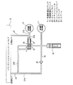
図1は本発明の実施の形態1におけるクラッチ油圧機構を備えたトランスミッション油圧回路である。
【0016】
図1は、前進側油圧クラッチ11より後進側油圧クラッチ12へ切り換えるときに使用されるクラッチ油圧機構を示している。
トランスミッションコントロールバルブ3より前進側油圧クラッチ11へ作動油が供給される油圧配管21は、2つに分岐され、一方の油圧配管21Aにチェックバルブ22が接続され、このチェックバルブ22に油圧配管23が接続され、この油圧配管23に前進側油圧クラッチ11が接続されている。
【0017】
また油圧配管23に(チェックバルブ22と前進側油圧クラッチ11間に)、油圧クラッチ11へ供給される作動油の一部を蓄積するアキュームレータ24が設けられている。
【0018】
また他方の油圧配管21Bはさらに2つに分岐されてコントロールバルブ25のポートAとポートBに接続されており、コントロールバルブ25のポートCが油圧配管23に接続されている。
【0019】
またトランスミッションコントロールバルブ3より後進側油圧クラッチ12へ作動油が供給される油圧配管27は、2つに分岐され、一方の油圧配管27Aは後進側油圧クラッチ12へ接続され、他方の油圧配管27Bはコントロールバルブ25のポートDに接続されている。
【0020】
コントロールバルブ25は、通常はポートBとポートC間が開放されており、ポートAへ油圧がかかると、スプリング31に抗してスプール32が移動してポートBとポートC間が遮断され、また油圧が無くなるとスプリング31により、またはポートDへ油圧がかかるとスプール32が戻り、再びポートBとポートC間が開放される構成となっている。
【0021】
上記構成による作用を説明する。
前進側に変速した場合、トランスミッションコントロールバルブ3よりの作動油は、油圧配管21,21A,23およびチェックバルブ22を介してアキュームレータ24を充填しながら前進側油圧クラッチ11へ供給され、前進側油圧クラッチ11を昇圧させる。また油圧配管21,21Bを介してコントロールバルブ25のポートAへ作動油が供給され、よってスプリング31に抗してスプール32が移動してポートBとポートC間が遮断され、すなわちスプール32によりポートCが閉じられ、油圧配管23は閉じられる。
【0022】
この状態で、速度段用油圧クラッチ(1速/2速/3速/4速)13〜16による変速が行われると、図2に示すように、前進側油圧クラッチ11へ供給されている作動油の油圧は瞬間低下するが、前進側油圧クラッチ11の油圧は、チェックバルブ22とコントロールバルブ25のスプール32によりブロックされ、かつアキュームレータ24の働きにより、その圧力が保持される。
【0023】
なお、スプリング31は上記瞬時の油圧低下でスプール32が戻らない適当な小さなばね力に設定されている。
また後進側に変速されると、トランスミッションコントロールバルブ3よりの作動油は、油圧配管27,27Aを介して後進側油圧クラッチ12へ供給され、後進側油圧クラッチ12を昇圧させる。また油圧配管27,27Bを介してコントロールバルブ25のポートDへ供給され、よってポートDへ油圧がかかることによりスプール32が戻り、再びポートBとポートC間が開放され、前進側油圧クラッチ11へ供給されていた作動油は、油圧配管23、ポートBとポートC間、配管21B,21を介してトランスミッションコントロールバルブ3へ戻され、前進側油圧クラッチ11の油圧は0となる。
【0024】
上記作用によれば、速度段用油圧クラッチ(1速/2速/3速/4速)13〜16による変速が行われた際に発生する作動油の油圧の瞬間低下により、前進側油圧クラッチ11の油圧が低下することが防止され、よって前進側油圧クラッチ11のスリップを防止でき、出力軸トルクの低下(トルク抜け)を防止することができる。
(実施の形態2)
上記実施の形態1では、変速時の作動油油圧の瞬間低下によるトルク抜けの対応を、前進側(または後進側)油圧クラッチ11また12の油圧の低下を防止することにより行っているが、実施の形態2では、変速時に作動油の油圧が瞬間に0近くまで低下することを避けることによりトルク抜けを防止するものである。
【0025】
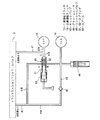
図3は本発明の実施の形態2におけるクラッチ油圧機構を備えたトランスミッション油圧回路である。
図3は、2速(2ND)油圧クラッチ14より1速(1ST)油圧クラッチ13へ切り換えるときに使用されるクラッチ油圧機構を示している。
【0026】
トランスミッションコントロールバルブ3より2速油圧クラッチ13へ作動油が供給される油圧配管41は、2つに分岐され、一方の油圧配管41Aにチェックバルブ42が接続され、このチェックバルブ42に油圧配管43が接続され、この油圧配管43に2速油圧クラッチ14が接続されている。
【0027】
また油圧配管43に(チェックバルブ42と速度段用油圧クラッチ間に)、2速油圧クラッチ14へ供給される作動油の一部を蓄積するアキュームレータ44が設けられている。
【0028】
また他方の油圧配管41Bはコントロールバルブ45のポートAに接続されており、コントロールバルブ45のポートBが油圧配管43に接続されている。
またトランスミッションコントロールバルブ3より1速油圧クラッチ13へ作動油が供給される油圧配管47は、2つに分岐され、一方の油圧配管47Aは1速油圧クラッチ13へ接続され、他方の油圧配管47Bはコントロールバルブ45のポートCに接続されている。
【0029】
コントロールバルブ45は、通常はポートAとポートB間が開放されており、ポートCへ油圧がかかると、まず第1スプリング51に抗してスプール52が移動してポートAとポートB間が遮断され、続いて油圧が上昇すると、第1スプリング51および第2スプリング53に抗してさらにスプール52が移動して再びポートAとポートB間が開放され、またポートCへの油圧が無くなると、スプリング51および53により、スプール52が戻り、ポートAとポートB間が開放される構成となっている。
【0030】
上記構成による作用を説明する。
2速に変速した場合、トランスミッションコントロールバルブ3よりの作動油は、油圧配管41,41A,43およびチェックバルブ42を介してアキュームレータ44を充填しながら2速油圧クラッチ14へ供給され、2速油圧クラッチ14を昇圧させる。
【0031】
この状態で、1速への変速が行われると、トランスミッションコントロールバルブ3よりの作動油は、油圧配管47,47Aを介して1速油圧クラッチ13へ供給され、1速油圧クラッチ13を昇圧させる。また油圧配管47,47Bを介して作動油がコントロールバルブ45のポートCへ供給され、ポートCへ油圧がかかるとスプリング51は弱く設定しているのでモジュレーション初期の低い油圧(たとえば2kg/cm2)でも、スプリング51の力に抗してスプール52がすばやく移動してポートAとポートB間が遮断され、すなわちスプール52によりポートBが閉じられ、油圧配管43は閉じられる。
【0032】
すると、2速油圧クラッチ14へ供給されている作動油はチェックバルブ42とコントロールバルブ45のスプール52によって逃げ場を失い、アキュームレータ44の設定圧力により図4(b)に示す棚状の油圧波形Psが形成される。
【0033】
さらにポートCへかかる油圧が上昇すると、さらにスプール52が移動してポートAとポートB間が開放され、2速油圧クラッチ14へ供給されていた作動油は、油圧配管43、ポートAとポートB間、配管41B,41を介してトランスミッションコントロールバルブ3へ戻され、2速油圧クラッチ14の油圧は0となる。
【0034】
上記作用によれば、速度段用油圧クラッチによる変速が行われた際に発生していた油圧の瞬間の低下(上記時間tの存在)を無くすことができ、変速時にも車両に十分なトルクを与えることができ、トルク抜けを防止することができる。
(実施の形態3)
上記実施の形態2の構成では、スプール52がすばやく移動しても、ポートAとポートB間が遮断されるには、短いが必ず時間を要し、この遮断までの短い時間に2速油圧クラッチ14の作動油は配管41B,41を介して放出され(トランスミッションコントロールバルブ3へ戻され)、アキュームレータ44の設定圧力より低下する。たとえばアキュームレータ44の設定圧力の12kg/cm2より10kg/cm2まで低下する。このとき、作動油の温度が高かったり、コントローラバルブ45の製作公差がきつく加工されてしまっているとき、あるいは1速油圧クラッチ13の油圧回路からの作動油の漏れが多いときなど、上記遮断までの短い時間が正常な時間よりは長い時間を要し、図6(a)に示すように、棚状の油圧波形Psが低下してトルク抜け防止効果が十分でなくなってしまう恐れがある。
【0035】
実施の形態3はこのような恐れを解消するものである。
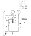
図5は本発明の実施の形態3におけるクラッチ油圧機構を備えたトランスミッション油圧回路であり、上記実施の形態2の油圧回路において、新たに油圧配管41Bに絞り48を挿入している。
【0036】
上記構成による作用を説明する。
2速に変速した場合、トランスミッションコントロールバルブ3よりの作動油は、油圧配管41,41A,43およびチェックバルブ42を介してアキュームレータ44を充填しながら2速油圧クラッチ14へ供給され、2速油圧クラッチ14を昇圧させる。
【0037】
この状態で、1速への変速が行われると、トランスミッションコントロールバルブ3よりの作動油は、油圧配管47,47Aを介して1速油圧クラッチ13へ供給され、1速油圧クラッチ13を昇圧させる。
【0038】
また油圧配管47,47Bを介して作動油がコントロールバルブ45のポートCへ供給され、よってポートCへ油圧がかかると、スプリング51は弱く設定しているのでモジュレーション初期の低い油圧(たとえば2kg/cm2)でも、スプリング51の力に抗してスプール52がすばやく移動してポートAとポートB間が遮断され、すなわちスプール52によりポートBが閉じられ、油圧配管43は閉じられる。
【0039】
すると、2速油圧クラッチ14へ供給されている作動油はチェックバルブ42とコントロールバルブ45のスプール52によって逃げ場を失い、アキュームレータ44の設定圧力で棚状の油圧波形Psが形成される。このとき(上記ポートAとポートB間が遮断されるまでの間)、絞り48により2速油圧クラッチ14の作動油の放出が抑制されることにより、安定した棚状の油圧波形Ps{図6(b)}が形成される。
【0040】
もし絞り48が無い場合、上述したように、棚状の油圧波形Psが低下し{図6(a)}、トルク抜け防止効果が十分でなくなってしまう恐れがある。
さらにポートCへかかる油圧が上昇すると、さらにスプール52が移動してポートAとポートB間が開放され、2速油圧クラッチ14へ供給されていた作動油は、油圧配管43、ポートAとポートB間、配管41B,41を介してトランスミッションコントロールバルブ3へ戻され、2速油圧クラッチ14の油圧は0となる。
【0041】
上記作用によれば、速度段用油圧クラッチによる変速が行われた際に発生していた油圧の低下(上記時間tの存在)を無くすことができ、変速時にも車両に十分なトルクを与えることができる。さらにクラッチの作動油を放出する油圧配管41Bに絞り48を挿入したことにより、トルク抜け防止に必要なクラッチ切り換え時の安定した棚状の油圧波形Psを得ることができる。
(実施の形態4)
上記実施の形態2の構成では、コントロールバルブ45は2本のスプリング51,53を使用した複雑な構造となっている。実施の形態4では、簡単な構造のコントロールバルブで同様の効果を得ようとするものである。
【0042】
図7は本発明の実施の形態4におけるクラッチ油圧機構を備えたトランスミッション油圧回路である。
図7は、2速(2ND)油圧クラッチ14より1速(1ST)油圧クラッチ13へ切り換えるときに使用されるクラッチ油圧機構を示している。上記実施の形態2の図3の構成と同一の構成には同一の符号を付して説明を省略する。
【0043】
油圧配管41Bは油圧配管41Cと油圧配管41Dの2つに分岐され、一方の油圧配管41Cがコントロールバルブ61のポートAに接続され、他方の油圧配管41Dが絞り49を介してコントロールバルブ61のポートBに接続されている。また油圧配管43がコントロールバルブ61のポートCに接続されている。
【0044】
またトランスミッションコントロールバルブ3より1速油圧クラッチ13へ作動油が供給される油圧配管47の他方の油圧配管47Bがコントロールバルブ61のポートDに接続されている。
【0045】
コントロールバルブ61は、ポートDへ油圧がかかるとスプリング63に抗してスプール62が移動するようになっており、ポートDへ油圧がかかっていない状態ではスプール62によりポートBが遮断され、またポートAとポートCはそれぞれ開放されており、ポートDへかかる油圧が上昇すると、スプリング63に抗してスプール62が移動してポートCとポートB間が連通される構成となっている。
【0046】
上記構成による作用を説明する。
2速に変速した場合、トランスミッションコントロールバルブ3よりの作動油は、油圧配管41,41A,43およびチェックバルブ42を介してアキュームレータ44を充填しながら2速油圧クラッチ14へ供給され、2速油圧クラッチ14を昇圧させる。またコントロールバルブ61内には、油圧配管41Bを介してポートAより、また油圧配管43を介してポートCより作動油が充填される。
【0047】
この状態で、1速への変速が行われると、トランスミッションコントロールバルブ3よりの作動油は、油圧配管47,47Aを介して1速油圧クラッチ13へ供給される。また油圧配管47,47Bを介して作動油がコントロールバルブ61のポートDへ供給される。
【0048】
また、これまで2速へ油圧を供給してきた配管41,41A,41B,41C,41Dの油圧は主回路側でドレンに連通し、速やかに0kg/cm2まで低下し、2速油圧クラッチ14を切ろうとするが、2速油圧クラッチ14にはアキュームレータ44の設定圧(たとえば10kg/cm2)により図8に示す棚状の油圧波形Psが得られる。
【0049】
続いて1速油圧クラッチ13への油圧が昇圧すると、コントロールバルブ61のスプール62は徐々にスプリング63に抗して移動して、ポートCとポートB間が連通される。
【0050】
すると、2速油圧クラッチ14へ供給されている作動油とアキュームレータ44に充填されている作動油は、油圧配管43、ポートCとポートB間、配管41D,41B,41を介してトランスミッションコントロールバルブ3へ戻され、2速油圧クラッチ14の油圧は0となる。このとき、図8に示すように、絞り49により2速油圧クラッチ14の作動油の放出が抑制されることにより、2速油圧クラッチ14は滑らかに切れ、よって1速油圧クラッチ13への動力の受け渡しが滑らかとなり、出力軸トルクの変化もより滑らかになる。
【0051】
なお、絞り49が無い場合、2速油圧クラッチ14の油圧は図8に2点鎖線で示すように油圧Psから急激に0に低下するため、出力軸トルクが2点鎖線で示すように乱れる恐れがある。
【0052】
上記作用によれば、速度段用油圧クラッチによる変速が行われた際に発生していた油圧の低下(上記時間tの存在)を無くすことができ、変速時にも車両に十分なトルクを与えることができる。さらにクラッチの作動油を放出する油圧配管41Dに絞り49を挿入したことにより、トルクの乱れを防止することができる。
【0053】
以上のように、速度段用油圧クラッチ13〜16による変速が行われた際に発生していた前進側油圧クラッチ11あるいは後進側油圧クラッチ12のスリップによるトルクの回復の遅れを解消でき、また上記時間tの存在を無くすことができ、変速時にも車両に十分なトルクを与えることができることにより、オペレータに変速時に与えていたトルク抜け感やショック、坂道での後戻り感などの違和感を解消することができる。
【0054】
【発明の効果】
以上述べたように本発明によれば、オペレータに変速時に与えていたトルク抜け感やショック、坂道での後戻り感などの違和感を解消することができる。
【図面の簡単な説明】
【図1】本発明の実施の形態1におけるクラッチ油圧機構を備えたトランスミッションの油圧回路図である。
【図2】同クラッチ油圧機構におけるクラッチ油圧と出力軸トルクの特性図である。
【図3】本発明の実施の形態2におけるクラッチ油圧機構を備えたトランスミッションの油圧回路図である。
【図4】同クラッチ油圧機構におけるクラッチ油圧の特性図である。
【図5】本発明の実施の形態3におけるクラッチ油圧機構を備えたトランスミッションの油圧回路図である。
【図6】同クラッチ油圧機構におけるクラッチ油圧の特性図である。
【図7】本発明の実施の形態4におけるクラッチ油圧機構を備えたトランスミッションの油圧回路図である。
【図8】同クラッチ油圧機構におけるクラッチ油圧と出力軸トルクの特性図である。
【図9】従来のトランスミッションの油圧回路図である。
【図10】従来のトランスミッションにおけるクラッチ油圧の特性図である。
【符号の説明】
1 チャージングポンプ
3 トランスミッションコントロールバルブ
4 トルクコンバータ
11 前進側油圧クラッチ
12 後進側油圧クラッチ
13 1速油圧クラッチ
14 2速油圧クラッチ
15 3速油圧クラッチ
16 4速油圧クラッチ
21,21A,21B,23,27,27A,27B,41,41A,41B,41C,41D,43,47,47A,47B 油圧配管
22,42 チェックバルブ
24,44 アキュームレータ
25,45,61 コントロールバルブ
31,51,53,63 スプリング
32,52,62 スプール[0001]
BACKGROUND OF THE INVENTION
The present invention relates to an industrial vehicle clutch hydraulic mechanism using a torque converter.
[0002]
[Prior art]
An example of a hydraulic circuit of a transmission of an industrial vehicle that uses a torque converter will be described with reference to FIG.
[0003]
In FIG. 9,
[0004]
The
(1) Forward (or reverse)
(2) Speed stage
The speed stage is set by engaging the two clutches.
[0005]
As shown in FIG. 10, the valve module mechanism changes the clutch oil pressure increase time (clutch oil pressure waveform) according to each speed stage to enable a smooth speed change. After the clutch oil pressure Pa at the stage returns to 0 immediately, the clutch oil pressure Pb after the shift gradually rises to complete the shift.
[0006]
[Problems to be solved by the invention]
However, in the conventional transmission mechanism, as shown in FIG. 10, the clutch hydraulic pressure Pa at the pre-shift gear stage decreases to a pressure close to 0, and the post-shift clutch hydraulic pressure Pb increases to give the vehicle sufficient torque. There is a time t until. At this time, the clutch hydraulic pressure of the entire circuit decreases momentarily, so the clutch hydraulic pressure of the forward
[0007]
Due to the existence of the time t and the delay in torque recovery due to the slip of the forward
[0008]
Accordingly, an object of the present invention is to provide a clutch hydraulic mechanism that can prevent a sense of discomfort given to an operator at the time of shifting.
[0011]
[Means for Solving the Problems]
In order to achieve the preceding object, the invention according to
[0012]
According to the above configuration, a part of the hydraulic fluid supplied to the speed stage hydraulic clutch is accumulated in the accumulator via the check valve before the speed change, and the speed change to the other speed stage hydraulic clutch is performed. The hydraulic oil supplied to the speed stage hydraulic clutch after the gear shift drives the control valve, shuts off the piping from which the hydraulic oil flows out from the accumulator, and then the hydraulic oil supplied to the hydraulic clutch after the gear shift. The hydraulic oil accumulated in the accumulator is confined until the hydraulic pressure rises and the pipe is opened . Therefore, the hydraulic pressure of the hydraulic clutch before the shift is maintained at the set pressure of the accumulator for a certain time.
[0013]
The invention according to
[0014]
According to the above configuration, when the hydraulic fluid of the speed stage hydraulic clutch before shifting is released from the control valve, the releasing speed is suppressed.
[0015]
DETAILED DESCRIPTION OF THE INVENTION
Hereinafter, embodiments of the present invention will be described with reference to the drawings. In addition, the same code | symbol is attached | subjected to the structure same as FIG. 9 of a prior art example, and description is abbreviate | omitted.
(Embodiment 1)
1 is a transmission hydraulic circuit including a clutch hydraulic mechanism according to
[0016]
FIG. 1 shows a clutch hydraulic mechanism used when switching from the forward
The
[0017]
Further, an
[0018]
The other
[0019]
Also, the
[0020]
The
[0021]
The operation of the above configuration will be described.
When shifting to the forward side, hydraulic oil from the
[0022]
In this state, when a speed change is performed by the speed stage hydraulic clutches (1st speed / 2nd speed / 3rd speed / 4th speed) 13 to 16, the operation supplied to the forward hydraulic clutch 11 as shown in FIG. Although the hydraulic pressure of the oil drops instantaneously, the hydraulic pressure of the forward hydraulic clutch 11 is blocked by the
[0023]
The
When the speed is shifted to the reverse side, the hydraulic oil from the
[0024]
According to the above operation, the forward hydraulic clutch is caused by the instantaneous drop in the hydraulic pressure of the hydraulic oil that is generated when the speed change is performed by the speed stage hydraulic clutch (1st speed / 2nd speed / 3rd speed / 4th speed) 13-16. Accordingly, it is possible to prevent the forward hydraulic clutch 11 from slipping and to prevent the output shaft torque from decreasing (torque loss).
(Embodiment 2)
In the first embodiment, the torque loss due to the instantaneous decrease in hydraulic oil pressure during shifting is performed by preventing the hydraulic pressure of the forward side (or reverse side) hydraulic clutch 11 or 12 from being reduced. In the second aspect, torque loss is prevented by avoiding that the hydraulic pressure of the hydraulic oil drops to near zero at the time of shifting.
[0025]
FIG. 3 shows a transmission hydraulic circuit provided with a clutch hydraulic mechanism according to
FIG. 3 shows a clutch hydraulic mechanism used when switching from the second speed (2ND) hydraulic clutch 14 to the first speed (1ST)
[0026]
The
[0027]
An
[0028]
The other
Also, the
[0029]
The
[0030]
The operation of the above configuration will be described.
When shifting to the second speed, hydraulic oil from the
[0031]
When a shift to the first speed is performed in this state, the hydraulic oil from the
[0032]
Then, the hydraulic oil supplied to the second-speed
[0033]
When the hydraulic pressure applied to the port C further increases, the
[0034]
According to the above-described operation, it is possible to eliminate the instantaneous decrease in hydraulic pressure (the presence of the time t) that has occurred when the gear shift by the speed stage hydraulic clutch is performed, and to apply sufficient torque to the vehicle even during the gear shift. And torque loss can be prevented.
(Embodiment 3)
In the configuration of the second embodiment, even if the
[0035]
FIG. 5 shows a transmission hydraulic circuit including a clutch hydraulic mechanism according to the third embodiment of the present invention. In the hydraulic circuit according to the second embodiment, a
[0036]
The operation of the above configuration will be described.
When shifting to the second speed, hydraulic oil from the
[0037]
When a shift to the first speed is performed in this state, the hydraulic oil from the
[0038]
When hydraulic oil is supplied to the port C of the
[0039]
Then, the hydraulic oil supplied to the second-speed
[0040]
If the
When the hydraulic pressure applied to the port C further increases, the
[0041]
According to the above operation, it is possible to eliminate the decrease in hydraulic pressure (existence of the time t) that occurred when the gear shift by the speed stage hydraulic clutch is performed, and to give sufficient torque to the vehicle even during the gear shift. Can do. Further, by inserting the
(Embodiment 4)
In the configuration of the second embodiment, the
[0042]
FIG. 7 shows a transmission hydraulic circuit including a clutch hydraulic mechanism according to Embodiment 4 of the present invention.
FIG. 7 shows a clutch hydraulic mechanism used when switching from the second speed (2ND) hydraulic clutch 14 to the first speed (1ST)
[0043]
The
[0044]
The other hydraulic piping 47 B of the
[0045]
In the
[0046]
The operation of the above configuration will be described.
When shifting to the second speed, hydraulic oil from the
[0047]
In this state, when the shift to the first speed is performed, the hydraulic oil from the
[0048]
In addition, the hydraulic pressures of the
[0049]
Subsequently, when the hydraulic pressure to the first-speed
[0050]
Then, the hydraulic oil supplied to the second speed
[0051]
If the
[0052]
According to the above operation, it is possible to eliminate the decrease in hydraulic pressure (existence of the time t) that occurred when the gear shift by the speed stage hydraulic clutch is performed, and to give sufficient torque to the vehicle even during the gear shift. Can do. Furthermore, torque disturbance can be prevented by inserting the
[0053]
As described above, it is possible to eliminate the delay in torque recovery caused by the slippage of the forward hydraulic clutch 11 or the reverse hydraulic clutch 12 that has occurred when the shift by the speed stage
[0054]
【The invention's effect】
As described above, according to the present invention, it is possible to eliminate a sense of incongruity such as a feeling of torque loss, a shock, or a feeling of back-turning on a hill that has been given to the operator during shifting.
[Brief description of the drawings]
FIG. 1 is a hydraulic circuit diagram of a transmission including a clutch hydraulic mechanism according to
FIG. 2 is a characteristic diagram of clutch hydraulic pressure and output shaft torque in the clutch hydraulic mechanism.
FIG. 3 is a hydraulic circuit diagram of a transmission provided with a clutch hydraulic mechanism in
FIG. 4 is a characteristic diagram of clutch hydraulic pressure in the clutch hydraulic mechanism.
FIG. 5 is a hydraulic circuit diagram of a transmission provided with a clutch hydraulic mechanism according to
FIG. 6 is a characteristic diagram of clutch hydraulic pressure in the clutch hydraulic mechanism.
FIG. 7 is a hydraulic circuit diagram of a transmission provided with a clutch hydraulic mechanism according to a fourth embodiment of the present invention.
FIG. 8 is a characteristic diagram of clutch hydraulic pressure and output shaft torque in the clutch hydraulic mechanism.
FIG. 9 is a hydraulic circuit diagram of a conventional transmission.
FIG. 10 is a characteristic diagram of clutch oil pressure in a conventional transmission.
[Explanation of symbols]
1
11 Forward hydraulic clutch
12 Reverse hydraulic clutch
13 1-speed hydraulic clutch
14 2-speed hydraulic clutch
15 3-speed hydraulic clutch
16 4-speed hydraulic clutch
21, 21A, 21B, 23, 27, 27A, 27B, 41, 41A, 41B, 41C, 41D, 43, 47, 47A, 47B Hydraulic piping
22, 42 Check valve
24, 44 Accumulator
25, 45, 61 Control valve
31, 51, 53, 63 Spring
32, 52, 62 spool
Claims (2)
各油圧クラッチへ供給される作動油の配管にそれぞれ、チェックバルブを介装し、
前記各チェックバルブと油圧クラッチ間にそれぞれ、油圧クラッチへ供給される作動油の一部を蓄積するアキュームレータを設け、
変速後の油圧クラッチへ供給される作動油により変速前の油圧クラッチに設けたアキュームレータから作動油が流出する配管を遮断し、続いて変速後の油圧クラッチへ供給される作動油の油圧が上昇し前記配管を開放するまで、前記チェックバルブとともに前記アキュームレータに蓄積された作動油を閉じ込め、変速前のクラッチの油圧を前記アキュームレータの設定圧力に一定時間保持するコントロールバルブを備えたこと
を特徴とするクラッチ油圧機構。In an industrial vehicle using a torque converter, a clutch hydraulic mechanism that switches a hydraulic clutch for each speed stage according to an operation of a transmission change lever,
A check valve is installed in each hydraulic oil pipe supplied to each hydraulic clutch.
An accumulator is provided between each of the check valves and the hydraulic clutch to store a part of the hydraulic oil supplied to the hydraulic clutch,
The hydraulic oil supplied to the hydraulic clutch after the shift shuts off the piping from which the hydraulic oil flows out of the accumulator provided in the hydraulic clutch before the shift, and then the hydraulic pressure of the hydraulic oil supplied to the hydraulic clutch after the shift increases. A clutch comprising a control valve that traps hydraulic oil accumulated in the accumulator together with the check valve until the piping is opened, and holds the hydraulic pressure of the clutch before shifting at a set pressure of the accumulator for a certain period of time. Hydraulic mechanism.
を特徴とする請求項1に記載のクラッチ油圧機構。 The clutch hydraulic mechanism according to claim 1 , wherein a throttle is attached to a pipe through which hydraulic oil of the hydraulic clutch before shifting flows out from the control valve .
Priority Applications (1)
| Application Number | Priority Date | Filing Date | Title |
|---|---|---|---|
| JP2000355112A JP4097397B2 (en) | 1999-12-07 | 2000-11-22 | Clutch hydraulic mechanism |
Applications Claiming Priority (3)
| Application Number | Priority Date | Filing Date | Title |
|---|---|---|---|
| JP11-346990 | 1999-12-07 | ||
| JP34699099 | 1999-12-07 | ||
| JP2000355112A JP4097397B2 (en) | 1999-12-07 | 2000-11-22 | Clutch hydraulic mechanism |
Publications (2)
| Publication Number | Publication Date |
|---|---|
| JP2001227568A JP2001227568A (en) | 2001-08-24 |
| JP4097397B2 true JP4097397B2 (en) | 2008-06-11 |
Family
ID=26578403
Family Applications (1)
| Application Number | Title | Priority Date | Filing Date |
|---|---|---|---|
| JP2000355112A Expired - Fee Related JP4097397B2 (en) | 1999-12-07 | 2000-11-22 | Clutch hydraulic mechanism |
Country Status (1)
| Country | Link |
|---|---|
| JP (1) | JP4097397B2 (en) |
-
2000
- 2000-11-22 JP JP2000355112A patent/JP4097397B2/en not_active Expired - Fee Related
Also Published As
| Publication number | Publication date |
|---|---|
| JP2001227568A (en) | 2001-08-24 |
Similar Documents
| Publication | Publication Date | Title |
|---|---|---|
| JP3392717B2 (en) | Control device for automatic transmission | |
| WO1997000391A1 (en) | Control device for an automatic transmission | |
| JP5620949B2 (en) | Control device for automatic transmission | |
| CN111316016A (en) | Control system for a multi-speed transmission and method therefor | |
| JP2942525B2 (en) | Hydraulic pressure control system for vehicle automatic transmission | |
| JP4806831B2 (en) | Hydraulic control system for automatic transmission for vehicles | |
| EP1184604B1 (en) | Control system for vehicular automatic transmission | |
| JP4097397B2 (en) | Clutch hydraulic mechanism | |
| JP4893432B2 (en) | Oil level adjustment device for automatic transmission | |
| US4616532A (en) | Automatic transmission hydraulic pressure control system with one-way fluid drain passage bypassing downshift timing subsystem | |
| US5833565A (en) | Oil pressure control system for automatic transmission | |
| CN114391072A (en) | Control device and control method for automatic transmission | |
| JP2007177868A (en) | Hydraulic equipment for multi-stage transmission | |
| JPH0730832B2 (en) | Automatic transmission control device | |
| JPS60231056A (en) | Hydraulic shift controlling method in automatic transmission for vehicles | |
| JPH0771575A (en) | Control device for hydraulically actuated transmission for vehicle | |
| RU2520958C2 (en) | System and method for pressure control in working assemblies | |
| JP2940415B2 (en) | Hydraulic control device for automatic transmission | |
| JP2885049B2 (en) | Automatic transmission hydraulic circuit | |
| JP2002276798A (en) | Hydraulic device for clutch | |
| US6889805B2 (en) | Clutch hydraulic mechanism | |
| JPS61116158A (en) | Control device for hydraulically operated transmission for vehicles | |
| JP3085030B2 (en) | Transmission control device for automatic transmission | |
| KR100581253B1 (en) | Hydraulic control system of automatic transmission for vehicles | |
| JPH07269685A (en) | Hydraulic control of automatic transmission |
Legal Events
| Date | Code | Title | Description |
|---|---|---|---|
| A621 | Written request for application examination |
Free format text: JAPANESE INTERMEDIATE CODE: A621 Effective date: 20040527 |
|
| A131 | Notification of reasons for refusal |
Free format text: JAPANESE INTERMEDIATE CODE: A131 Effective date: 20061031 |
|
| A977 | Report on retrieval |
Free format text: JAPANESE INTERMEDIATE CODE: A971007 Effective date: 20061101 |
|
| A521 | Written amendment |
Free format text: JAPANESE INTERMEDIATE CODE: A523 Effective date: 20061228 |
|
| TRDD | Decision of grant or rejection written | ||
| A01 | Written decision to grant a patent or to grant a registration (utility model) |
Free format text: JAPANESE INTERMEDIATE CODE: A01 Effective date: 20080212 |
|
| A61 | First payment of annual fees (during grant procedure) |
Free format text: JAPANESE INTERMEDIATE CODE: A61 Effective date: 20080311 |
|
| R150 | Certificate of patent or registration of utility model |
Free format text: JAPANESE INTERMEDIATE CODE: R150 |
|
| FPAY | Renewal fee payment (event date is renewal date of database) |
Free format text: PAYMENT UNTIL: 20110321 Year of fee payment: 3 |
|
| FPAY | Renewal fee payment (event date is renewal date of database) |
Free format text: PAYMENT UNTIL: 20120321 Year of fee payment: 4 |
|
| FPAY | Renewal fee payment (event date is renewal date of database) |
Free format text: PAYMENT UNTIL: 20130321 Year of fee payment: 5 |
|
| S531 | Written request for registration of change of domicile |
Free format text: JAPANESE INTERMEDIATE CODE: R313531 |
|
| FPAY | Renewal fee payment (event date is renewal date of database) |
Free format text: PAYMENT UNTIL: 20130321 Year of fee payment: 5 |
|
| R350 | Written notification of registration of transfer |
Free format text: JAPANESE INTERMEDIATE CODE: R350 |
|
| FPAY | Renewal fee payment (event date is renewal date of database) |
Free format text: PAYMENT UNTIL: 20130321 Year of fee payment: 5 |
|
| FPAY | Renewal fee payment (event date is renewal date of database) |
Free format text: PAYMENT UNTIL: 20130321 Year of fee payment: 5 |
|
| S111 | Request for change of ownership or part of ownership |
Free format text: JAPANESE INTERMEDIATE CODE: R313111 |
|
| FPAY | Renewal fee payment (event date is renewal date of database) |
Free format text: PAYMENT UNTIL: 20130321 Year of fee payment: 5 |
|
| R360 | Written notification for declining of transfer of rights |
Free format text: JAPANESE INTERMEDIATE CODE: R360 |
|
| FPAY | Renewal fee payment (event date is renewal date of database) |
Free format text: PAYMENT UNTIL: 20130321 Year of fee payment: 5 |
|
| R370 | Written measure of declining of transfer procedure |
Free format text: JAPANESE INTERMEDIATE CODE: R370 |
|
| FPAY | Renewal fee payment (event date is renewal date of database) |
Free format text: PAYMENT UNTIL: 20130321 Year of fee payment: 5 |
|
| FPAY | Renewal fee payment (event date is renewal date of database) |
Free format text: PAYMENT UNTIL: 20140321 Year of fee payment: 6 |
|
| LAPS | Cancellation because of no payment of annual fees |