JP4097319B2 - Method and apparatus for automatic setting of drawing rod position - Google Patents
Method and apparatus for automatic setting of drawing rod position Download PDFInfo
- Publication number
- JP4097319B2 JP4097319B2 JP16162998A JP16162998A JP4097319B2 JP 4097319 B2 JP4097319 B2 JP 4097319B2 JP 16162998 A JP16162998 A JP 16162998A JP 16162998 A JP16162998 A JP 16162998A JP 4097319 B2 JP4097319 B2 JP 4097319B2
- Authority
- JP
- Japan
- Prior art keywords
- servo motor
- stretching rod
- stretching
- current value
- rod
- Prior art date
- Legal status (The legal status is an assumption and is not a legal conclusion. Google has not performed a legal analysis and makes no representation as to the accuracy of the status listed.)
- Expired - Lifetime
Links
Images


Classifications
-
- B—PERFORMING OPERATIONS; TRANSPORTING
- B29—WORKING OF PLASTICS; WORKING OF SUBSTANCES IN A PLASTIC STATE IN GENERAL
- B29C—SHAPING OR JOINING OF PLASTICS; SHAPING OF MATERIAL IN A PLASTIC STATE, NOT OTHERWISE PROVIDED FOR; AFTER-TREATMENT OF THE SHAPED PRODUCTS, e.g. REPAIRING
- B29C49/00—Blow-moulding, i.e. blowing a preform or parison to a desired shape within a mould; Apparatus therefor
- B29C49/08—Biaxial stretching during blow-moulding
- B29C49/10—Biaxial stretching during blow-moulding using mechanical means for prestretching
- B29C49/122—Drive means therefor
- B29C49/123—Electric drives, e.g. linear motors
Description
【0001】
【発明の属する技術分野】
本発明は二軸延伸ブロー成形装置で用いられるプリフォームの延伸ロッドの上昇位置および中間位置の自動設定方法及びその装置に関する。
【0002】
【従来の技術】
二軸延伸ブロー成形は、加熱ラインで加熱されたプリフォーム(有底パリソン)を金型内に設置し、延伸ロッドによるプリフォームの延伸と同時にエアーを吹き込み膨張させて成形品(例えばボトル)を得る。この場合、種々の成形品サイズに対応し、成形前準備段階で延伸ロッドの上昇位置および中間位置を設定する必要があるが、従来におけるこの延伸ロッドの位置設定作業は、リミットスイッチやストッパなどを用い、オペレータの経験と勘による試行錯誤で長時間を要している。
【0003】
【発明が解決しようとする課題】
しかしながら、成形前準備段階で延伸ロッドの上昇位置および中間位置を設定するのに、オペレータの経験と勘による試行錯誤で長時間を要するのでは、作業能率が悪いばかりか、熟練者でなければ二軸延伸ブロー成形装置の稼働ができず、したがって、稼働効率が低下して製品コストにも悪影響する。
【0004】
そこで、この発明は、種々のボトルサイズに応じた延伸ロッドの位置設定を自動的に、非熟練者でも簡便・迅速かつ容易にできるようにすることを目的とする。
【0005】
【課題を解決するための手段】
前記目的を達成するため、本発明は、二軸延伸ブロー成形装置にて、プリフォームを取り付けていない状態で金型と底型で形成されたキャビティで、底型に延伸ロッドが接触しボールねじの回転が拘束されてサーボモータの電流値が上昇する点を検出し、サーボモータエンコーダにより位置を検出して上昇位置とする。上昇位置は実作業での成形製品底部厚さに対応した位置をタッチパネルより入力し演算処理により修正される。また、プリフォームを取り付け延伸ロッドがプリフォーム内側底部に接触した時にサーボモータの電流値が上昇する点を検出し、サーボモータエンコーダにより位置を求め延伸中間位置とし、この中間位置までの延伸ロッドの速度とその後の速度を任意にできる延伸ロッド位置の自動設定装置を提供する。
【0006】
【発明の実施の形態】
以下、この発明の実施の形態を図に基づき説明する。この発明の二軸延伸ブロー成形装置は、図1に示すように、基台10上に4つのスプロケット11を略四辺形状に配置し、これらにチェーンコンベア12をエンドレスに掛け回してプリフォームの加熱ライン1が、また、基台28上に一対の離間したスプロケット29に第2チェーンコンベア30をエンドレスに掛け回して略長円形状の延伸ブローライン2がそれぞれ独立して形成される。加熱ライン1にはプリフォーム供給ライン3が接続されるとともに、複数の加熱装置4と加熱ヒーター5が配設され、加熱ヒーター5に対面して反射板5aが設置され、加熱ライン1から延伸ブローライン2へのプリフォームの供給に移載装置6が配設されている。延伸ブローライン2は、前記チェーンコンベア12とほぼ同じ構造であるがシャフト31の間隔を長くしたリンクプレート30a,30aを所定の間隔で相対面させてその両端部をシャフト31で回動可能に両隣の一対のリンクプレート30a,30aと連結してなる第2チェーンコンベア30である。延伸ブローライン2には型締装置7と製品取出装置8とが配設されるとともに、加熱ライン1において、プリフォーム供給ライン3の付近と移載装置6の付近に、それぞれ温度センサーA,Bが配置される。
【0007】
したがって、プリフォームPはプリフォーム供給ライン3のガイド板40,40間にて形成されるシュートを下り、把持反転装置43で受け止められ、把持反転装置43で加熱ライン1のキャリアにおけるマンドレルにそれぞれ装填され、一方、チェーンコンベア12はサーボモーター等の駆動源13にて図1中矢示(イ)方向へ間欠回動する。そして、プリフォームPが加熱ライン1に搬送されると、温度センサーAがその温度を測定し、これをコンピュータに記憶させる。そこで、プリフォームPは加熱装置4にて所要の温度に加熱され、加熱装置4を出たプリフォームPは加熱ヒーター5の領域に間欠移動し、その後、プリフォームPは加熱された所定温度を保有しながら移送され、移載装置6にて延伸ブローライン2に供給される。また、温度センサーBは加熱後のプリフォームの温度を測定し、温度センサーA,Bの測定温度を比較し、延伸ブローライン2における成形に必要な温度にするための、加熱装置4及び加熱ヒーター5での加熱をその差分に応じた駆動をするために必要な指令を自動的に与える。
【0008】
型締装置7は、図1及び図2に示すように、第2チェーンコンベア30を一対の二つ割りのキャビティ70a,70aを有する金型70,70間の中央下部に配置するようにベース71を配設してある。ベース71の下方に一対の下部タイロッド73,73が配設され、下部タイロッド73,73と同様の上部タイロッド74,74の一端部に、一方の金型70を固定したプレート75が固定され、このプレート75に対面して他方の金型70を固定したプレート76がタイロッド73,74にスライド可能に挿通され、タイロッド73,74の他端部は型締基台77を貫通してプレート78に一体結合されている。型締基台77には回転円板79が回転自在に軸支され、この回転円板79にリンク80,80の一端部が180度で相対向して回転可能に軸着され、リンク80,80の他端部はそれぞれ前記プレート76,78にそれぞれ回転可能に軸着されている。
【0009】
なお、プレート75,76の下部はそれぞれスライダー81を介して所定距離を有するレール82に支承され、スライダー81を介してプレート75,76は該レール82に沿って移動できる。したがって、サーボモーター駆動のシャフト79aで回転円板79を回転させてリンク80,80がほぼ一直線状に整列するとプレート75,76が互いに近接して対面する一対の金型70,70が接触し、それぞれキャビティ70a,70aが形成される。この回転円板79が逆回転すれば対面する一対の金型70,70は開くことができる。
【0010】
型締装置7の対面する金型70,70間の中央下部に延伸ブロー装置90が配置される。この延伸ブロー装置90は、図2,3に示すように、前記ベース71の下面に形成された開溝71aに対面して所定寸法で侵入して前記一対の第2キャリア32の接触ヘッド34,34とそれぞれ接触すべき一対のヘッド部91,91を有するシリンダブロック91aを固定した所定長さのプレート92と、これに平行なプレート93,94との間に、一対の延伸ロッド95,95とボールねじ96,96及びガイドロッド97,97とを所定間隔で配設したものである。プレート92はフレーム98に水平に支持されている。延伸ロッド95の上端部は前記ヘッド部91を貫通し、他端部はプレート93に連結固定してある。なお、延伸ロッド95,95にはエア供給口107が設けられ、ヘッド部91にはプリフォームP内に空気を吹き込むべきブローエア用穴が延伸ロッド95との間に形成されている。
【0011】
ボールねじ96はフレーム98とプレート94に両端部がそれぞれ回転可能に連結され、プレート93にナットブロック101で係合し、プレート94の外部でプーリー102が軸着されている。プーリー102には無端ベルト103が捲回され、プーリー102は無端ベルト103を介してサーボモーター105の出力プーリー104で回転駆動される。ガイドロッド97の下端部はプレート94に、上端部はフレーム98にそれぞれ固定され、プレート93はスライドブロック106を介して摺動可能に係合している。
【0012】
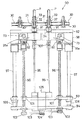
型締装置7の金型70,70間の中央上部に底形昇降装置110が配置される。この装置110は、図2に示すように、成形製品の底面を形成すべき底型111を、対面する金型70,70間の中央部において昇降可能に、支持パイプ112の下端部に連結したもので、支持パイプ112は昇降プレート113に固定され、昇降プレート113は固定プレート114に固定したシリンダ115のピストンロッド116に吊支されている。一方、底型111の中心部を貫通して押え棒117が昇降可能に、支持パイプ112を貫通して上方へ延伸し、固定プレート114aに固定したシリンダ118のピストンロッド119に連結されている。シリンダ115は底型111を対面する金型70,70間の上部に挟持させ、また、シリンダ118はプリフォームの底部を押えながらストレッチするための押え棒117を所定のストロークにて軸方向へ往復移動させる。
【0013】
したがって、延伸ブローライン2では、プリフォームPは移載装置6から、図1中矢示(ロ)方向へ間欠駆動される第2チェーンコンベア30に移送され、図2に示す延伸ブロー装置90と底型昇降装置110が金型70,70に挟持されて二軸延伸ブロー成形がなされる。
【0014】
ここで、底型昇降装置110で底型111を下降させ、対面する金型70,70が閉じられて形成されるキャビティ70a,70aにおいて、プリフォームPが取り付けられていない状態にて、延伸ブロー装置90の延伸ロッド95は成形前準備作業として、延伸ロッド95の上昇位置設定を行う。この上昇位置設定は、図4に示すように、エンコーダが組み込まれたサーボモーター105を回転させる電流値xAと底型111の下端部に延伸ロッド95が上昇接触しボールねじの回転が拘束されたときに発生するサーボモータ105の電流値(xA+α)を図5に示す回路にて処理し自動的に位置を求める。
【0015】
図5において、CPU120からサーボモーター105をまわす位置指令I/F121を通じてサーボアンプ122に指令を出力する。サーボアンプ122からサーボモーター105を回転させたときの電流値をxAとする。底型111の下端部に延伸ロッド95が上昇し接触するとボールねじ96,96の回転が拘束され、サーボアンプ122から拘束に打ち勝とうとする電流を流し始める。この電流を流し始める変化点の検出方法は、無負荷時(上昇中の電流値)の電流平均値に対し(+αA)の上限不感帯値をタッチパネル付きディスプレイ124から設定できるようにしておき、サンプリングタイム毎のパルス値をメモリーしておいて上限不感帯値を越える直前の電流平均値を越えた点を定点とする。サーボモーター105は(×A+α)の電流値を越えると安全のため停止させる。
【0016】
この位置はプリフォームPが取り付けられていない上昇位置であり、実作業に対応した成形製品底部厚さをタッチパネル付きディスプレイ124より入力し演算処理により上昇位置の修正を行う。また、求めた延伸ロッド95の位置はタッチパネル付きディスプレイ124に表示する。
【0017】
次いでプリフォームPを取り付けた状態で延伸ロッド95を上昇させ、延伸ロッド95がプリフォームP内側底部に接触しボールねじ96,96の回転が拘束され、サーボアンプ122から拘束に打ち勝とうとする電流値(×A+α′)より変化点を検出する。
【0018】
この変化点の検出は無負荷運転時(上昇中の電流値)の電流平均値に対し(+α′A)の上限不感帯値をタッチパネル付きディスプレイ124から設定できるようにしておき、サンプリングタイム毎のパルス値をメモリーしておいて上限不感帯値を越える直前の電流平均値を越えた点を定点とする。
【0019】
その位置を延伸中間位置とし、該延伸中間位置までの延伸ロッド95の速度とその後の速度を任意に設定できるようにする。サーボモーター105は(×A+α′)の電流値を越えると安全のため停止させる。
【0020】
以上のサーボアンプ122の電流値の変化をCPU120で処理することにより、延伸ロッド95の上昇位置と中間位置を自動的に設定できる。
【0021】
かくして、延伸ロッド95の上昇位置と中間位置を自動的に設定した後は、二軸延伸ブロー時に延伸ロッド95がプリフォームPに延伸するとともに、エア供給口107から低圧及び高圧エアを吹き込む。プリフォームPは空気が吹き込まれてキャビティ70a,70aに沿い製品に成形される。延伸ロッド95がヘッド部91内に引き込まれて延伸ブローが終了すると、金型70,70が互いに離反し第2チェーンコンベア30の間欠移動にて一対の成形品が型締装置7から離れ、製品取出装置8のシャフト131で回転するチャック130で把持して延伸ブローライン2から外され、製品出口へと移送されるというものである。
【0022】
【発明の効果】
以上説明したように、この発明によれば、種々のボトルサイズに応じた延伸ロッドの位置設定を自動的に迅速にでき、従来勘で位置設定を行っていたものが、非熟練者でも簡便・迅速かつ容易にセットできる効果を奏する。
【図面の簡単な説明】
【図1】二軸延伸ブロー成形装置の平面図である。
【図2】延伸ブローラインの要部断面側面図である。
【図3】延伸ブローラインの要部断面正面図である。
【図4】サーボモータの電流値変化を示すグラフである。
【図5】延伸ロッドの位置設定回路ブロック図である。
【符号の説明】
P…プリフォーム
1…加熱ライン
2…延伸ブローライン
3…プリフォーム供給ライン
5…加熱ヒーター
6…移載装置
7…型締装置
8…製品取出し装置
70…金型
70a…キャビティ
95…延伸ロッド
96…ボールねじ
105…サーボモーター
111…底型
120…CPU
121…位置指令I/F
122…サーボアンプ
123…ディスプレイI/F
124…タッチパネル付きディスプレイ[0001]
BACKGROUND OF THE INVENTION
The present invention relates to a method and apparatus for automatically setting a rising position and an intermediate position of a stretching rod of a preform used in a biaxial stretch blow molding apparatus.
[0002]
[Prior art]
In biaxial stretch blow molding, a preform (bottomed parison) heated in a heating line is placed in a mold, and air is blown and expanded simultaneously with the stretching of the preform by a stretching rod to form a molded product (for example, a bottle). obtain. In this case, it is necessary to set the lifted rod's lift position and intermediate position at the pre-molding preparation stage in response to various molded product sizes. It takes a long time by trial and error based on the experience and intuition of the operator.
[0003]
[Problems to be solved by the invention]
However, it takes a long time for trial and error based on the operator's experience and intuition to set the lift and intermediate positions of the stretching rod in the pre-molding preparation stage. The axial stretch blow molding apparatus cannot be operated, and therefore the operating efficiency is lowered and the product cost is adversely affected.
[0004]
Accordingly, an object of the present invention is to enable the position setting of the stretching rod in accordance with various bottle sizes to be automatically, easily, quickly and easily even by an unskilled person.
[0005]
[Means for Solving the Problems]
In order to achieve the above object, the present invention provides a biaxial stretch blow molding device in which a draw rod is in contact with a bottom mold in a cavity formed by a mold and a bottom mold in a state where a preform is not attached. The point at which the rotation of the servo motor is restricted and the current value of the servo motor rises is detected, and the position is detected by the servo motor encoder to obtain the raised position. The ascending position is corrected by calculation processing by inputting a position corresponding to the thickness of the bottom of the molded product in actual work from the touch panel. Also, when the preform is attached, the point where the current value of the servo motor rises when the stretching rod comes into contact with the inner bottom of the preform is detected, the position is determined by the servo motor encoder, and the stretching intermediate position is determined. Provided is an automatic setting device for a stretching rod position in which a speed and a subsequent speed can be arbitrarily set.
[0006]
DETAILED DESCRIPTION OF THE INVENTION
Hereinafter, embodiments of the present invention will be described with reference to the drawings. In the biaxial stretch blow molding apparatus of the present invention, as shown in FIG. 1, four
[0007]
Therefore, the preform P descends the chute formed between the
[0008]
As shown in FIGS. 1 and 2, the mold clamping device 7 has a
[0009]
The lower portions of the
[0010]
A
[0011]
Both ends of the
[0012]
A
[0013]
Therefore, in the stretch blow line 2, the preform P is transferred from the transfer device 6 to the
[0014]
Here, the
[0015]
In FIG. 5, the
[0016]
This position is an ascending position where the preform P is not attached, and the thickness of the bottom of the molded product corresponding to the actual work is input from the
[0017]
Next, the stretching
[0018]
This change point is detected by setting an upper dead zone value of (+ α′A) for the average current value during no-load operation (current value during ascending) from the
[0019]
The position is set as the stretching intermediate position, and the speed of the stretching
[0020]
By processing the change in the current value of the
[0021]
Thus, after the rising position and the intermediate position of the stretching
[0022]
【The invention's effect】
As described above, according to the present invention, the position of the stretching rod according to various bottle sizes can be automatically and quickly set, and the position setting based on the conventional intuition is simple even for non-experts. There is an effect that can be set quickly and easily.
[Brief description of the drawings]
FIG. 1 is a plan view of a biaxial stretch blow molding apparatus.
FIG. 2 is a cross-sectional side view of an essential part of a stretch blow line.
FIG. 3 is a sectional front view of an essential part of a stretch blow line.
FIG. 4 is a graph showing changes in the current value of the servo motor.
FIG. 5 is a block diagram of an extension rod position setting circuit.
[Explanation of symbols]
P ... Preform 1 ... Heating line 2 ... Stretch blow line 3 ...
121 ... Position command I / F
122 ...
124 ... Display with touch panel
Claims (5)
Priority Applications (1)
| Application Number | Priority Date | Filing Date | Title |
|---|---|---|---|
| JP16162998A JP4097319B2 (en) | 1998-06-10 | 1998-06-10 | Method and apparatus for automatic setting of drawing rod position |
Applications Claiming Priority (1)
| Application Number | Priority Date | Filing Date | Title |
|---|---|---|---|
| JP16162998A JP4097319B2 (en) | 1998-06-10 | 1998-06-10 | Method and apparatus for automatic setting of drawing rod position |
Publications (2)
| Publication Number | Publication Date |
|---|---|
| JPH11348101A JPH11348101A (en) | 1999-12-21 |
| JP4097319B2 true JP4097319B2 (en) | 2008-06-11 |
Family
ID=15738826
Family Applications (1)
| Application Number | Title | Priority Date | Filing Date |
|---|---|---|---|
| JP16162998A Expired - Lifetime JP4097319B2 (en) | 1998-06-10 | 1998-06-10 | Method and apparatus for automatic setting of drawing rod position |
Country Status (1)
| Country | Link |
|---|---|
| JP (1) | JP4097319B2 (en) |
Families Citing this family (9)
| Publication number | Priority date | Publication date | Assignee | Title |
|---|---|---|---|---|
| JP2006240238A (en) * | 2005-03-07 | 2006-09-14 | Ishizuka Glass Co Ltd | Stretching rod lift device of pet bottle molding machine |
| JP5244823B2 (en) * | 2007-02-15 | 2013-07-24 | カーハーエス コーポプラスト ゲーエムベーハー | Method and apparatus for blow molding containers |
| CN102036803A (en) * | 2008-05-28 | 2011-04-27 | 伊莫拉Sacmi机械合作公司 | System for blowing plastic containers, specifically bottles |
| DE102008038782A1 (en) * | 2008-08-04 | 2010-02-11 | Khs Corpoplast Gmbh & Co. Kg | Method and apparatus for blow molding containers |
| CN103391839B (en) * | 2011-02-15 | 2016-05-11 | 帝斯克玛股份有限公司 | For the negative drawing bar of machine health and processing |
| FR2998207B1 (en) * | 2012-11-20 | 2015-01-16 | Sidel Participations | METHOD OF STRETCH BLOWING A CONTAINER, COMPRISING A MEASUREMENT OF THE SHIFT OF THE STRETCH ROD DURING A BOXING OPERATION |
| FR3023503B1 (en) * | 2014-07-11 | 2016-07-29 | Sidel Participations | MEASURING THE BOXING RACE BY THE STRETCH FUNCTION IN A CONTAINER MANUFACTURING FACILITY |
| FR3024071B1 (en) * | 2014-07-25 | 2016-08-19 | Sidel Participations | METHOD FOR CONTROLLING A PROCESS FOR BLOWING PLASTIC CONTAINERS |
| DE102017120161A1 (en) * | 2017-09-01 | 2019-03-07 | Krones Aktiengesellschaft | System and method for condition monitoring of linear drives of stretching / blowing machines |
-
1998
- 1998-06-10 JP JP16162998A patent/JP4097319B2/en not_active Expired - Lifetime
Also Published As
| Publication number | Publication date |
|---|---|
| JPH11348101A (en) | 1999-12-21 |
Similar Documents
| Publication | Publication Date | Title |
|---|---|---|
| US2515093A (en) | Machine for making hollow articles | |
| JP4097319B2 (en) | Method and apparatus for automatic setting of drawing rod position | |
| US8376730B2 (en) | Method of clamping material and a material-clamping unit used therefor | |
| KR920002362B1 (en) | Temperature control blow molding equipment in injection spretch blow molding machine | |
| GB2062533A (en) | Blow moulding method | |
| JP4095418B2 (en) | I. S. Blow mold assembly for molding machine | |
| JPH1148316A (en) | Control method for stretch rod in biaxial criention blow molding device and device for the same | |
| WO2018076400A1 (en) | Intelligent plastic pipe molding machine | |
| ITPI20010021A1 (en) | METHOD AND EQUIPMENT FOR THE LONGITUDINAL ORIENTATION OF FOOTWEAR ITEMS | |
| CN1128512A (en) | Blow molding apparatus | |
| US4290745A (en) | Apparatus for blow molding | |
| CN207580732U (en) | A kind of product circulation wire body | |
| JP2000043131A (en) | Biaxial stretch blow molding method and molding machine therefor | |
| CN2536384Y (en) | Automatic energy-saving plastic bottle blower | |
| JPH11170352A (en) | Method for biaxially orienting blow molding and its preform heating device | |
| JPH1148323A (en) | Method and apparatus for biaxially orientating blow molding method | |
| JP2004074209A (en) | Multiple press transfer apparatus | |
| JP4920495B2 (en) | Resin sheet thermoforming equipment | |
| CN112297337A (en) | Scald preventing type injection moulding device of detect reagent box production | |
| KR200436584Y1 (en) | Protector manufacturing device | |
| CN216068637U (en) | Semi-automatic plastic sucking machine with novel structure | |
| KR100397546B1 (en) | Device for automatically separating vacuum package | |
| JPH1148327A (en) | Method and device for controlling preform temperature in biaxially orienting blow molding method | |
| KR101378551B1 (en) | Blowing Apparatus For The PET Bottle Apparatus And Setting Method Used Blowing Apparatus | |
| CN112693099B (en) | Heating and air-blowing molding integrated plastic bottle manufacturing device |
Legal Events
| Date | Code | Title | Description |
|---|---|---|---|
| A621 | Written request for application examination |
Free format text: JAPANESE INTERMEDIATE CODE: A621 Effective date: 20050511 |
|
| A977 | Report on retrieval |
Free format text: JAPANESE INTERMEDIATE CODE: A971007 Effective date: 20070413 |
|
| A131 | Notification of reasons for refusal |
Free format text: JAPANESE INTERMEDIATE CODE: A131 Effective date: 20070417 |
|
| A521 | Request for written amendment filed |
Free format text: JAPANESE INTERMEDIATE CODE: A523 Effective date: 20070613 |
|
| TRDD | Decision of grant or rejection written | ||
| A01 | Written decision to grant a patent or to grant a registration (utility model) |
Free format text: JAPANESE INTERMEDIATE CODE: A01 Effective date: 20080226 |
|
| A61 | First payment of annual fees (during grant procedure) |
Free format text: JAPANESE INTERMEDIATE CODE: A61 Effective date: 20080311 |
|
| R150 | Certificate of patent or registration of utility model |
Free format text: JAPANESE INTERMEDIATE CODE: R150 |
|
| FPAY | Renewal fee payment (event date is renewal date of database) |
Free format text: PAYMENT UNTIL: 20110321 Year of fee payment: 3 |
|
| FPAY | Renewal fee payment (event date is renewal date of database) |
Free format text: PAYMENT UNTIL: 20120321 Year of fee payment: 4 |
|
| FPAY | Renewal fee payment (event date is renewal date of database) |
Free format text: PAYMENT UNTIL: 20130321 Year of fee payment: 5 |
|
| FPAY | Renewal fee payment (event date is renewal date of database) |
Free format text: PAYMENT UNTIL: 20130321 Year of fee payment: 5 |
|
| FPAY | Renewal fee payment (event date is renewal date of database) |
Free format text: PAYMENT UNTIL: 20140321 Year of fee payment: 6 |
|
| R250 | Receipt of annual fees |
Free format text: JAPANESE INTERMEDIATE CODE: R250 |
|
| R250 | Receipt of annual fees |
Free format text: JAPANESE INTERMEDIATE CODE: R250 |
|
| R250 | Receipt of annual fees |
Free format text: JAPANESE INTERMEDIATE CODE: R250 |
|
| R250 | Receipt of annual fees |
Free format text: JAPANESE INTERMEDIATE CODE: R250 |
|
| R250 | Receipt of annual fees |
Free format text: JAPANESE INTERMEDIATE CODE: R250 |
|
| EXPY | Cancellation because of completion of term |