JP4097116B2 - Image forming apparatus, control method thereof, and control apparatus - Google Patents
Image forming apparatus, control method thereof, and control apparatus Download PDFInfo
- Publication number
- JP4097116B2 JP4097116B2 JP2001002905A JP2001002905A JP4097116B2 JP 4097116 B2 JP4097116 B2 JP 4097116B2 JP 2001002905 A JP2001002905 A JP 2001002905A JP 2001002905 A JP2001002905 A JP 2001002905A JP 4097116 B2 JP4097116 B2 JP 4097116B2
- Authority
- JP
- Japan
- Prior art keywords
- storage means
- usage status
- status information
- replacement part
- main body
- Prior art date
- Legal status (The legal status is an assumption and is not a legal conclusion. Google has not performed a legal analysis and makes no representation as to the accuracy of the status listed.)
- Expired - Fee Related
Links
Images


Landscapes
- Electrophotography Configuration And Component (AREA)
- Control Or Security For Electrophotography (AREA)
Description
【0001】
【発明の属する技術分野】
本発明は、プロセスカートリッジ等の交換部品を使用するプリンタ、複写機、ファクシミリ等の画像形成装置、並びにその制御方法及び制御装置に関し、より詳細には、交換部品の使用に伴う使用状況情報等、部品に固有の情報を部品に設けた不揮発メモリに格納して、適正な交換部品の保守、管理を可能にする画像形成装置、並びにその制御方法及び制御装置に関する。
【0002】
【従来の技術】
電子写真プロセスにより画像形成を行うプリンタ等の画像形成装置では、画像形成プロセスに用いる電子写真感光体やトナー等の部品は、消耗等により使用限界があるので、従来から、プロセスカートリッジの形で交換部品として用意されている。カートリッジの多くは、これまで使い捨ての形をとり、消費されて使用限界に達すると、新品に交換して古い部品は廃棄していた。
しかしながら、近年、環境保護、エコロジー思想を背景として、カートリッジの中身(例えばトナー)のみを交換して、カートリッジ自体(メカ部品)はリサイクルして利用されるケースも増えてきている。このような再生利用が行われると、一方でメカ部品等のリサイクルされる部分に破損が生じて画像形成装置に危険を及ぼす可能性も高くなってくることになる。
そこで、カートリッジの使用状況(使用に伴う状態変化)等のカートリッジに固有の情報をカートリッジに設けた不揮発メモリに記憶させておき、その情報により、リサイクルの管理を含め、交換部品の保守、管理を行うようにするという提案がなされている。
このような方法により情報の管理をする際に、使用状況の変化をとらえ、カートリッジに設けた不揮発メモリの記憶情報を書き換える処理を行う必要があるが、この処理は本体側のCPUが行う。従って、カートリッジの本体への装着時にカートリッジから不揮発メモリに記憶されている情報の読み出しを行い、画像形成動作により、使用状況に変化が生じる度にその変化をとらえ、変化後に得られる情報を本体側からカートリッジの不揮発メモリに書き戻す動作が行われることになる。
【0003】
【発明が解決しようとする課題】
ところで、カートリッジに不揮発メモリを設け、本体側のCPUにより読み出し・書き込みアクセスを行うために、両者間を電気的に接続(データバス線、給電線等で接続)する必要があるが、カートリッジは本体に着脱されるので、電気的な接続も挿抜可能なコネクタを介して行われることになる。
このようなコネクタにより本体とカートリッジを接続する方法による場合、これまでは、カートリッジの着脱に伴う電気的な接続、切断動作と、カートリッジに設けたメモリチップ(不揮発メモリ)にアクセスを行う動作のタイミングが調整されていなかった。従って、アクセスの途中で(当然、装置の電源オン状態で)、カートリッジが不意に取り外され、コネクタが切断されることがある。このようなときには、チャタリングノイズが生じたり、アクセス途中の切断が起きる(比較的処理速度の遅いシステムを用いて書き込み・読み出しアクセスを行う場合に起きる可能性が高い)ことになり、誤書き込みが発生することがあって、必ずしも、正しい情報が、カートリッジメモリに格納されない可能性がある。
しかしながら、従来においては、こうした予期しないコネクタの切断という異常動作により起きるエラーの発生により不正な情報が書き込まれても、それに対して有効な補償手段を講じていなかった。
本発明は、装置本体に着脱可能な交換部品(例えば、トナーカートリッジ)を有し、交換部品に設けた不揮発性メモリに、該部品の使用状況(使用に伴う状態変化)等のカートリッジに固有の情報を保存する画像形成装置における上述の従来技術の問題点に鑑みてなされたものであって、その目的は、電源オン状態にある装置本体とカートリッジを接続するコネクタの切断により不揮発性メモリに誤書き込みが発生しても、誤書き込みの発生の可能性があることをチェックすることができるようにし、チェック結果により誤った情報が保存されることが回避されるように動作を制御し、また、正しい情報を保存することにより誤書き込みを補償する手段を備え、より信頼性の高い交換部品の保守、管理を可能にする画像形成装置を提供することにある。
【0004】
【課題を解決するための手段】
請求項1の発明は、着脱可能な交換部品を少なくとも一部に用いた画像形成手段と、装置本体に内蔵した読み出し・書き込み可能な第1の記憶手段と、前記交換部品に設けられ、前記交換部品の識別情報及び前記交換部品の使用に伴う状態変化を表す使用状況情報を保持する読み出し・書き込み可能な不揮発性の第2の記憶手段と、前記第2の記憶手段へのアクセスを行うための装置本体と交換部品間の接続手段と、を有する画像形成装置であり、装置への電源投入時に初期化処理として、装置本体に装着された交換部品の第2の記憶手段に保持されている識別情報及び使用状況情報を前記第1の記憶手段に書き込む手段と、画像形成時、装着された交換部品の使用に伴う状態変化を検知して、各時点の使用状況情報を求める手段と、該求められた使用状況情報を前記第1の記憶手段及び第2の記憶手段に書き込む手段と、前記交換部品の装置本体への前記初期化処理後の再装着時に、前記第1の記憶手段と第2の記憶手段に保持されている情報の整合性有無をチェックする手段と、識別情報が整合しない場合に、第1の記憶手段に保持されている識別情報及び使用状況情報を第2の記憶手段に保持されている識別情報及び使用状況情報により書き換え、識別情報が整合し、使用状況情報が整合しない場合に、第2の記憶手段に保持されている使用状況情報を第1の記憶手段に保持されている使用状況情報により書き換える手段と、を備えたことを特徴とする画像形成装置である。
【0005】
請求項2の発明は、着脱可能な交換部品を少なくとも一部に用いた画像形成手段と、装置本体に内蔵した読み出し・書き込み可能な第1の記憶手段と、前記交換部品に設けられ、前記交換部品の識別情報及び前記交換部品の使用に伴う状態変化を表す使用状況情報を保持する読み出し・書き込み可能な不揮発性の第2の記憶手段と、前記第2の記憶手段へのアクセスを行うための装置本体と交換部品間の接続手段と、を有する画像形成装置の制御方法であり、装置への電源投入時に初期化処理として、装置本体に装着された交換部品の第2の記憶手段に保持されている識別情報及び使用状況情報を前記第1の記憶手段に書き込む手工程と、画像形成時、装着された交換部品の使用に伴う状態変化を検知して、各時点の使用状況情報を求める工程と、該求められた使用状況情報を前記第1の記憶手段及び第2の記憶手段に書き込む工程と、前記交換部品の装置本体への前記初期化処理後の再装着時に、前記第1の記憶手段と第2の記憶手段に保持されている情報の整合性の有無をチェックする工程と、識別情報が整合しない場合に、第1の記憶手段に保持されている識別情報及び使用状況情報を第2の記憶手段に保持されている識別情報及び使用状況情報により書き換え、識別情報が整合し、使用状況情報が整合しない場合に、第2の記憶手段に保持されている使用状況情報を第1の記憶手段に保持されている使用状況情報により書き換える工程と、を備えたことを特徴とする画像形成装置の制御方法である。
【0006】
請求項3の発明は、着脱可能な交換部品を少なくとも一部に用いた画像形成手段と、装置本体に内蔵した読み出し・書き込み可能な第1の記憶手段と、前記交換部品に設けられ、前記交換部品の識別情報及び前記交換部品の使用に伴う状態変化を表す使用状況情報を保持する読み出し・書き込み可能な不揮発性の第2の記憶手段と、前記第2の記憶手段へのアクセスを行うための装置本体と交換部品間の接続手段と、を有する画像形成装置の装置本体に設けられた制御装置であり、装置への電源投入時に初期化処理として、装置本体に装着された交換部品の第2の記憶手段に保持されている識別情報及び使用状況情報を前記第1の記憶手段に書き込む手段と、画像形成時、装着された交換部品の使用に伴う状態変化を検知して、各時点の使用状況情報を求める手段と、該求められた使用状況情報を前記第1の記憶手段及び第2の記憶手段に書き込む手段と、前記交換部品の装置本体への前記初期化処理後の再装着時に、前記第1の記憶手段と第2の記憶手段に保持されている情報の整合性の有無をチェックする手段と、識別情報が整合しない場合に、第1の記憶手段に保持されている識別情報及び使用状況情報を第2の記憶手段に保持されている識別情報及び使用状況情報により書き換え、識別情報が整合し、使用状況情報が整合しない場合に、第2の記憶手段に保持されている使用状況情報を第1の記憶手段に保持されている使用状況情報により書き換える手段と、を備えたことを特徴とする画像形成装置の制御装置である。
【0008】
【発明の実施の形態】
本発明を添付する図面とともに示す以下の実施例に基づき説明する。図1は、本発明による画像形成装置の実施例の構成を示す概略図である。ここに示す画像形成装置は、装置本体に対し着脱可能にプロセスカートリッジを装備するものである。図1を参照して、本例の画像形成装置をより詳細に説明すると、画像形成装置5本体内に、プロセスカートリッジ2が装着状態で示されている。プロセスカートリッジ2は、感光体11、帯電ローラ3、クリーニング手段を備えた廃トナー回収部6、現像手段を備えたトナー収納部4等で構成され、ここで電子写真プロセスの処理の多くの部分が行われる。また、画像形成装置5内には、感光体11に光(レーザ)ビーム書込を行うための光書込ユニット1を備え、そのユニットは、ポリゴンモータ、ポリゴンミラー、Fθレンズ、レーザダイオード、ミラー等で構成される。図1を参照して装置の動作の概略を、図中矢印にて示す記録紙の流れに沿い説明すると、先ず給紙トレイ8に収納された記録紙9は、感光体11に向けて搬送される。感光体11は、時計方向に回転駆動され、その際帯電ローラ3によって表面を帯電され、光書込ユニット1からレーザ光が照射されて感光体11上に静電潜像が形成される。この潜像は現像手段を備えたトナー収納部4を通る時トナーによって可視像化される。感光体11上の可視像は、転写ローラ10により、感光体11へ搬送された記録紙9に転写され、その後定着ローラ12に搬送され、そこで記録紙9上の可視像は定着され、画像形成装置5の外部へ排紙される。
【0009】
また、本実施例の画像形成装置のプロセスカートリッジ2には、カートリッジと一体に読み出し・書き込み可能な不揮発メモリ(以下「カートリッジメモリ」と記す)を持つICチップが実装された基板と基板につながるコネクタ部を設け、プロセスカートリッジに係わる各種のデータをカートリッジメモリに記憶するようにしている。
カートリッジメモリに記憶されるデータとしては、カートリッジの識別情報(例えば、製造番号等のカートリッジを同定できる情報を含む)及び使用状況情報として例えば、リサイクル回数、トナー残量、停止枚数カウント値、感光体ドラムの回転時間、廃トナー蓄積量が含まれる。なお、この他に、マシンID、バージョン、メーカー、地域、カラー等が書き込まれていても良い。
一方、本実施例の画像形成装置は、本体側にも画像形成動作に係わる各種のデータを記憶するための読み出し・書き込み可能な不揮発性メモリ(以下「本体不揮発メモリ」と記す)を備える。本体不揮発メモリに記憶されるデータは、実施形態により異なり、後記の実施例にて述べる。
【0010】
図2は、本実施例の画像形成装置の装置本体の制御部とカートリッジメモリ及び本体メモリとの関係を示す回路ブロック図である。同図に示すように、本体から着脱可能に(図示の破線で切り離される)不揮発性のカートリッジメモリ20が設けられ、画像形成装置本体側にも本体不揮発メモリ17が内蔵され、いずれの不揮発性メモリ(EEPROM)も装置本体のCPU14によって読み出し・書き込み可能に構成されている。本例では、本体不揮発メモリ17はCPUバスに接続され、又、カートリッジメモリ20は対カートリッジ通信デバイス18を介してCPUバスに接続することによりアクセス(間接的なものも含めて)を可能にされる。
CPU14は画像形成装置全体の動作の制御を司るもので、画像形成装置本体にはCPU14の制御下にCPUバスを介してソフトウェア、プログラミングデータ等を記憶するメモリとしてROM15及び制御動作等の実行時に使用されるRAM16、各種センサ等を含むその他のI/Oデバイス19を備える。
なお、カートリッジメモリ20には、図示のデータ通信用のラインの外に給電線が挿抜可能にコネクタ(図示せず)を介して接続されており、コネクタは電源オン状態で接続、遮断がなされる。
【0011】
次に、上記した画像形成装置において、電源オン状態で装置本体とカートリッジを接続するコネクタが切断されたことにより発生しうるカートリッジメモリ20への誤書き込みのチェックに係わる実施例を説明する。
この実施例は、カートリッジメモリ20に保持すると同一の情報を本体側の記憶手段にも保持させるようにして、両者の整合性をチェックし、整合している場合に誤書き込みが起きなかったことを確認し、整合しない場合に誤った情報が保存されることを回避するように動作を制御するものである。このチェックには、少なくともカートリッジが識別できる製造番号及び画像形成動作に係わり変化する使用状況を表す情報を用いる。
第1の実施例は、誤書き込みのチェックに用いる情報を画像形成装置本体側の本体不揮発メモリ17に保持することによるものである。
図3に、本実施例における本体不揮発メモリ17(図3(A))及びカートリッジメモリ20(図3(B))に記憶されているデータのデータマップを示す。図示のように、本体不揮発メモリ17には、カートリッジメモリ20に記憶される情報と同一の製造番号、使用状況情報をコピーして記憶する。なお、本体不揮発メモリ17には装置の保守、管理に必要なその他の情報、例えば、画像形成動作の制御に用いる定着温度、レジスト位置調整、画像濃度、印刷枚数カウント値等も書き込まれる。
【0012】
以下に、本実施例の制御フローを説明する。
このフローは、CPU14により実行され、カートリッジの装着により電気的な接続がなされる場合に、カートリッジメモリ20への誤書き込みがあったかをチェックし、チェック結果に従って次に行う処理動作、即ち、NGの場合の処理と、動作可とした場合、動作により変化する情報の管理動作を行うようにするものである。
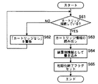
図5は、本実施例の制御フローを示す。本フローは、装置の電源オン状態で適宜のタイミングで実行される。
図5を参照し、このフローによる制御動作を説明する。図示のフローでは、先ず、カートリッジが接続されているか否かを調べる(S41)。これは、カートリッジが接続されていなければ(S41−NO)、「カートリッジなし」の警告を報知して(S42)、カートリッジが、セットされるのを待ち、カートリッジがセットされ、コネクタによる接続を確認したら、直ちに誤書き込みのチェック動作を始めるようにするために行う。
ここで、ユーザーにより、カートリッジがセットされ、カートリッジの接続を確認した後、直ちにカートリッジメモリ20から通信デバイス18を通して、カートリッジメモリ20に保存されている各種情報を読み出す(S43)。読み出された情報の中には少なくともカートリッジ識別情報としての製造番号、使用状況情報が含まれる。
続いて、本体不揮発メモリ17に保存されている情報を読み出す(S44)。本体不揮発メモリ17に保存されている情報は、カートリッジ交換時に、書き換えた情報、或いは前回の画像形成動作後に変化した使用状況情報をカートリッジメモリ20に更新、保存すると同時に、コピーして保存した情報(これらの情報には少なくとも製造番号、使用状況情報が含まれている)である。したがって、製造番号が一致する場合に、書き込みに誤りが生じなければ、両メモリには同一の使用状況情報が保存されていることになる。
【0013】
そこで、本フローでは、両メモリから読み出した情報の整合性をチェックし、不整合がある場合、整合する場合、それぞれに対応した動作を行う。
フローでは、最初に、両メモリから読み出した製造番号が同じかをチェックする(S45)。ここで、両者の番号が異なる場合は、カートリッジの交換が行われたと考えられるので、「カートリッジの不整合が発生」した旨の警告を表示し(S47)、番号の更新を促し、本フローのスタート時のステップに戻す。番号の更新は、手動で書き換えることも可能であるし、新品検知があれば自動更新も可能であり、既知の手段により更新処理を行い、番号を一致させる。番号を整合させることにより、スタート時のステップに戻すループを抜けることができる。
製造番号が、一致した場合(S45−YES)、次に、使用状況情報の整合性をチェックする(S46)。この使用状況情報とは、例えば、トナー残量情報であるとか、感光体ドラムの回転時間であったりする。この情報が同一であれば、カートリッジメモリ20への誤書き込みもなく、正常な状態に情報が管理されているので、画像形成動作を行っても問題はない。なお、ここでもカートリッジ交換が行われた場合には、更新処理が必要である。更新処理をしないと、スタート時のステップに戻すループを抜けることができない。
製造番号が一致したが、使用状況情報に不整合がある場合(S46−NO)であり、かつ新品等の交換が行われず、従って更新処理をしないというケースでは、カートリッジメモリ20への誤書き込みが発生したと推定されるので、「カートリッジの不整合が発生」した旨の警告を表示する(S47)。また、この場合には、カートリッジメモリ20の保存情報にエラーが含まれており、このままこの情報を用いると、適正な管理ができないので、画像形成動作を行わせないようにする。本フローにおいては、スタート時のステップに戻すループを抜けることがない。
【0014】
製造番号と使用状況情報の整合を確認し、画像形成動作を行っても問題のない条件が整ったところで、カートリッジが未接続ではないことを確認する(S48)。確認後(S48−NO)、画像形成動作などが行われた場合に対応できるようにするために、画像形成動作などにより変わる使用状況の変化を監視する(S49)。
使用状況に変化があった場合に(S49−YES)、保存している使用状況情報の更新処理を行う必要がある。その場合は、カートリッジメモリ20に更新、保存する(S50)と同時に、本体不揮発メモリ17にコピーして保存し(S51)、カートリッジ側と本体側の両方に同一データの更新を行い、整合をはかる。なお、情報の更新を行う毎に、カートリッジの接続状態をチェックし、ヌケを早急に検知する必要がある。
また、ステップS48において、カートリッジが未接続ではないことが確認できない場合(S48−YES)には、本フローのスタート時のステップに戻す。
【0015】
次に、電源オン状態で装置本体とカートリッジを接続するコネクタが切断されたことにより発生しうるカートリッジメモリ20への誤書き込みのチェックに係わる第2の実施例について説明する。
第1の実施例は、誤書き込みのチェックに用いる情報を画像形成装置本体側の本体不揮発メモリ17に保持することによるものであったが、第2の実施例においては、画像形成装置本体側の揮発性の記憶手段であるRAM16に保持することによるものである。RAM16を用いることにより、第1の実施例で用いたビット単価が高い不揮発メモリによるコストアップを抑え、ビット単価の安いRAM(揮発メモリ)でミラーリングして、信頼性の向上を図ろうとするものである。
図4に、本実施例における装置本体のRAM16(図4(A))、本体不揮発メモリ17及びカートリッジメモリ20(図4(B))に記憶されているデータのデータマップを示す。図示のように装置本体のRAM16には、カートリッジメモリ20に記憶される情報と同一の製造番号、使用状況情報をコピーして記憶する。なお、本体不揮発メモリ17には装置の保守、管理に必要なその他の情報、例えば、画像形成動作の制御に用いる定着温度、レジスト位置調整、画像濃度、印刷枚数カウント値等も書き込まれる。また、装置本体のRAM16には、本体不揮発メモリ17から取り込んだその他の情報、及びその他の領域にROM15から取り込んだソフトウェア、プログラミングデータ等を記憶する。
【0016】
以下に、本実施例の制御フローを説明する。
フローは、CPU14により実行され、カートリッジの装着により電気的な接続がなされる場合に、カートリッジメモリ20への誤書き込みがあったかをチェックし、チェック結果に従って次に行う処理動作、即ち、NGの場合の処理と、動作可とした場合、動作により変化する情報の管理動作を行うようにするものである。
この実施例では、チェックに用いるデータをミラーリングするためにRAM16を用い、装置を電源オフとすると、RAM16の過去のデータは消えてしまうので、電源投入時に初期化処理を行う必要がある。
図6は電源投入時の初期化フローを示す。図6のフローでは、先ず、カートリッジが接続されているか否かを調べる(S61)。これは、カートリッジが接続されていなければ(S41−NO)、「カートリッジなし」の警告を報知して(642)、カートリッジが、セットされるのを待ち、カートリッジがセットされ、コネクタによる接続を確認したら、直ちに誤書き込みのチェック動作を始めるようにするためである。従って、電源オンでフローを開始するが、カートリッジが接続するまではRAM16にデータが記憶されない。
ここで、ユーザーにより、カートリッジがセットされ、カートリッジの接続を確認した後、直ちにカートリッジメモリ20から通信デバイス18を通して、カートリッジメモリ20に保存されている各種情報を読み出す(S63)。読み出された情報の中には少なくとも製造番号、使用状況情報が含まれる。
続いて、本体のRAM16に、ステップS63でカートリッジメモリ20から読み出された情報を書き込む(S64)。このようにして、両メモリに同一の製造番号、使用状況情報が保存される。
この後、初期化終了フラグをセットして(S65)、このフローを終了させる。
【0017】
次いで、図6の初期化フローに続けて行われる誤書き込みのチェックに係わるフローを実行する。
図7は、本実施例の制御フローを示す。本フローは、上記初期化処理後に適宜のタイミングで実行され、カートリッジの装着により電気的な接続がなされる場合に、カートリッジメモリ20への誤書き込みがあったかをチェックし、チェック結果に従って次に行う処理動作、即ち、NGの場合の処理と、動作可とした場合、動作により変化する情報の管理動作を行うようにするものである。
図7を参照し、このフローによる制御動作を説明する。図示のフローでは、先ず、初期化終了フラグがセットされているか否かを調べ(S71)、初期化処理が行われており、そのフラグセットを確認したら、次に初期化後にユーザーによりカートリッジが外される場合があるので、再度カートリッジがセットされているか否かを確認する(S72)。
カートリッジのセットが確認された場合、接続フラグがセットされているか否かを調べる(S73)。これは、現在セットされているカートリッジの情報がRAM16に保持されているかを調べるために行う。つまり、今回のチェックが、未接続から接続に変化したところかどうかを接続フラグにより判断する。接続されたばかりの時には、接続されたカートリッジの情報をRAM16に書き込んだ時にセットするフラグがセットされていないのでそれを知ることが可能である。
【0018】
接続フラグがセットされていない場合(S73−NO)、未だ接続されたカートリッジの情報の書き込みをしていないので、カートリッジ情報をRAM16へ書き込むが、先ず接続フラグをセットする処理をして、今回の処理で現在セットされているカートリッジ情報がRAM16に書き込まれることをフラグにより表す(S74)。
その後、カートリッジメモリ20から通信デバイス18を通して、カートリッジメモリ20に保存されている製造番号、使用状況情報を含むカートリッジ情報を読み出し(S75)、読み出した情報の中の製造番号と、接続前からRAM16に保持されている製造番号の整合性をチェックする(S76)。
製造番号の整合性のチェックの結果、整合している場合に、次いで使用状況情報の整合性のチェックを行う(S77)。チェックの結果、使用状況情報も整合する場合に(S77−YES)、接続されたカートリッジは接続前と同一で、情報の書き込みも必要がないと判断し、フローを終了させる。
【0019】
他方、使用状況情報が整合しない場合に(S77−NO)、接続されたカートリッジは、以前に切断された時に誤書き込みがあったことが推定されるので、カートリッジメモリ20には、本体のRAM16に保持されている使用状況情報等の情報を適正なデータとして書き込む(S78)。本体で保持する情報に合わせる理由は、カートリッジは、非同期で、活電挿抜されるので、メモリアクセス中のプロテクトが難しく、電源がオフされるまでは、CPUバスに直結しているRAM16のほうが、信頼性が高いと判断し、カートリッジ情報に上書きをする。
また、ステップS76で製造番号の整合性のチェックの結果、整合していない場合は(S76−NO)、接続されたカートリッジは接続前と異なるカートリッジに交換されたと判断されるので、ステップS75でカートリッジメモリ20から読み出した製造番号を本体のRAM16に書き込み(S82)、同様に、使用状況情報等の情報もRAM16に書き込んで(S83)、フローを終了させる。
【0020】
接続フラグがセットされていない場合の上記したステップ(S74以降のステップ)を経ると、本体のRAM16には適正なデータが書き込まれることになるので、画像形成動作を行っても問題のない条件が整ったことになり、それを接続フラグのセットにより確認し(ステップS73−YES)、確認後、画像形成動作などが行われた場合に対応できるようにするために、画像形成動作などにより変わる使用状況の変化を監視する(S79)。
使用状況に変化があった場合に(S79−YES)、保存している使用状況情報の更新処理を行う必要がある。その場合は、カートリッジメモリ20に更新、保存する(S80)と同時に、本体RAM16にコピーして保持し(S81)、カートリッジ側と本体側の両方に同一データの更新を行い、整合をはかった後、フローを終了させる。
なお、本フローの開始時に、初期化終了フラグを確認した後、カートリッジの接続をステップS72でチェックする。このステップで、接続が確認されない、即ち非接続状態である場合、接続フラグがセットされた状態のままであると、矛盾が生じるので、接続フラグのセットを確認し(S84)、セットされている場合には接続フラグをリセットする処理を行う(S85)。
また、本体RAM16を用いる実施例として、図7に示すように、不整合時に自動的にRAM16のデータをカートリッジメモリ20データにより書き換えるか、或いはカートリッジメモリ20のデータをRAM16により書き換えて画像形成動作を起動させる例を示したが、かかる不整合時に画像形成動作を起動させず、カートリッジ交換或いはデータの修正をマニュアルにより行う図5に示したと同様の対応によることが可能である。この場合、図7のステップS76以降のフローを図5のステップS44以降のフローに置き換えることにより実施することが可能である。
【0021】
電源オン状態で装置本体とカートリッジを接続するコネクタが切断されたことにより発生しうるカートリッジメモリ20への誤書き込みのチェックに係わる第3の実施例について説明する。
第3の実施例は、上記の実施例において、使用状況情報の整合性のチェックを行っているが、このチェックを行う場合に、各情報毎に有効性(整合性)の判断基準を設定することにより必要以上の書き込み動作を行わないようにして、CPUの負担を軽減し、装置のパフォーマンスの向上を図るようにするものである。
図8は、本実施例の制御フローを示す。本フローは、上記の実施例では、使用状況情報の整合性をチェックするステップに適用するものであり、第2の実施例においては、図7のフローにおけるステップS77,S78(同図中、破線の楕円にて囲まれた部分)を図8のモジュールを差し替えることにより実施し得る。図8を参照し、このフローによる制御動作を説明する。図示のフローでは、使用状況情報をトナー残量、ドラム回転時間、廃トナー蓄積量として、それぞれのデータ毎にその有効性をステップS91,S93,S95で判断する。有効性の判断は、カートリッジメモリ20と本体RAM16に保持されているデータを比較し、その差値を情報毎に設定した基準値に従って、その有効性を判断する。基準値はトナー残量、ドラム回転時間、廃トナー蓄積量等のそれぞれの情報に適した値を設定可能として、適正な動作の確保を図る。
ステップS91,S93,S95で、カートリッジメモリ20に書き込まれているデータが有効であると判断された場合は、データの書き換え処理を行わず、また有効と判断できない場合に、カートリッジメモリ20に書き込まれているデータの書き換え処理をそれぞれステップS92,S94,S96で行うようにする。
【0022】
なお、上記実施例における交換部品(カートリッジ)は、電子写真プロセスによる画像形成に用いる感光体、帯電ローラ、トナー等の構成部品を含むプロセスカートリッジを例示し、主にトナーの使用状態に係わる動作を示したが、交換部品として、例えば、トナーカートリッジ(トナーボトル)や感光体ユニットのような単一部品であっても良い。また、画像形成装置が他の方式による装置、例えばインクジェット方式の画像形成装置であっても良く、この場合、交換部品としてインクカートリッジへの適用が可能である。
【0023】
【発明の効果】
交換部品の活線挿抜によって交換部品側の不揮発性記憶手段への誤書き込みが生じても、誤った情報を保存することが回避され、より適正な交換部品の情報管理が可能となり、装置の信頼性を向上させることができる。
【図面の簡単な説明】
【図1】 本発明による画像形成装置の実施例の構成を示す概略図である。
【図2】 プロセスカートリッジに設けた不揮発性メモリ(カートリッジメモリ)と装置本体の制御部の関係を示す回路ブロック図である。
【図3】 本体不揮発メモリ(A)及びカートリッジメモリ(B)に記憶されているデータのデータマップを示す。
【図4】 装置本体のRAMと本体不揮発メモリ(A)、及びカートリッジメモリ(B)に記憶されているデータのデータマップを示す。
【図5】 カートリッジメモリへの誤書き込みチェックに係わる制御フローを示す。
【図6】 電源投入時の初期化処理として、使用状況情報等のミラーリング処理を含むフローを示す。。
【図7】 初期化フロー(図6)に続けて行われる誤書き込みのチェックに係わる制御フローを示す。
【図8】 図7の使用状況情報の整合性をチェックするステップに適用するフローを示す。
【符号の説明】
1…光書込ユニット、 2…プロセスカートリッジ、
4…現像手段を備えたトナー収納部、
5…画像形成装置、
6…クリーニング手段を備えた廃トナー回収部、
11…感光体ドラム、 14…CPU、
15…ROM、 16…RAM、
17…不揮発メモリ(本体メモリ)、18…対カートリッジ通信デバイス、
20…カートリッジ不揮発メモリ。[0001]
BACKGROUND OF THE INVENTION
The present invention relates to an image forming apparatus such as a printer, a copying machine, and a facsimile machine using replacement parts such as a process cartridge, And its control method and More specifically regarding the control device, information specific to the part, such as usage status information associated with the use of the replacement part, is stored in the non-volatile memory provided in the part to enable maintenance and management of the appropriate replacement part. Forming equipment, And its control method and The present invention relates to a control device.
[0002]
[Prior art]
In an image forming apparatus such as a printer that forms an image by an electrophotographic process, the parts such as the electrophotographic photosensitive member and toner used in the image forming process are limited due to wear. It is prepared as a part. Many of the cartridges have so far been in a disposable form, and when they are consumed and reach the limit of use, they are replaced with new ones and old parts are discarded.
However, in recent years, with the background of environmental protection and ecology, there are increasing cases in which only the cartridge contents (for example, toner) are replaced and the cartridge itself (mechanical parts) is recycled. When such recycling is performed, on the other hand, there is a high possibility that the recycled parts such as mechanical parts will be damaged, causing danger to the image forming apparatus.
Therefore, information specific to the cartridge, such as the cartridge usage status (changes in use status), is stored in the nonvolatile memory provided in the cartridge, and maintenance and management of replacement parts, including recycling management, is performed using this information. Proposals have been made to do so.
When managing information by such a method, it is necessary to perform a process of recognizing changes in the usage status and rewriting information stored in the nonvolatile memory provided in the cartridge. This process is performed by the CPU on the main body side. Therefore, the information stored in the non-volatile memory is read from the cartridge when the cartridge is mounted on the main body, the change is detected every time the use status changes by the image forming operation, and the information obtained after the change is stored on the main body side. The operation of writing back to the nonvolatile memory of the cartridge is performed.
[0003]
[Problems to be solved by the invention]
By the way, a nonvolatile memory is provided in the cartridge, and in order to perform read / write access by the CPU on the main body side, the two need to be electrically connected (connected by a data bus line, a power supply line, etc.). Therefore, electrical connection is also made through a connector that can be inserted and removed.
In the case of using the method of connecting the main body and the cartridge by such a connector, until now, the timing of the electrical connection and disconnection operation associated with the attachment and detachment of the cartridge and the operation of accessing the memory chip (nonvolatile memory) provided in the cartridge Was not adjusted. Therefore, in the middle of access (naturally, when the apparatus is powered on), the cartridge may be removed unexpectedly and the connector may be disconnected. In such a case, chattering noise occurs or disconnection occurs during access (it is likely to occur when writing / reading access is performed using a system with a relatively slow processing speed), and erroneous writing occurs. Therefore, the correct information may not necessarily be stored in the cartridge memory.
However, in the past, even if incorrect information is written due to the occurrence of an error caused by such an abnormal operation of unexpected connector disconnection, no effective compensation means has been provided.
The present invention has a replacement part (for example, a toner cartridge) that can be attached to and detached from the apparatus main body, and a nonvolatile memory provided in the replacement part has a cartridge specific to the cartridge, such as a use status (state change accompanying use) of the part. The present invention has been made in view of the above-described problems in the conventional image forming apparatus for storing information. The purpose of the image forming apparatus is to error the nonvolatile memory by disconnecting the connector that connects the apparatus main body and the cartridge in the power-on state. Even if writing occurs, it is possible to check that there is a possibility of erroneous writing, control the operation so that incorrect information is not saved due to the check result, Provided is an image forming apparatus having a means for compensating for erroneous writing by storing correct information, and enabling maintenance and management of more reliable replacement parts. Located in.
[0004]
[Means for Solving the Problems]
According to the first aspect of the present invention, there is provided an image forming unit using at least a part of a removable replacement part, and a first readable / writable storage unit built in the apparatus main body. The above Provided in replacement parts, Said Replacement part identification information and Represents a change in state associated with the use of the replacement part An image forming apparatus comprising: a readable / writable non-volatile second storage unit that holds usage status information; and a connection unit between an apparatus main body and a replacement part for accessing the second storage unit And Means for writing identification information and usage status information held in the second storage means of the replacement part mounted on the apparatus main body into the first storage means as an initialization process upon power-on of the apparatus; and image formation Means for detecting a change in state associated with the use of the mounted replacement part and obtaining usage status information at each point of time, and the obtained usage status information in the first storage means and the second storage means At the time of re-installation after the initialization process to the device body of the replacement part and the replacement part, Check the consistency of information held in the first storage means and the second storage means If the identification information and the identification information do not match, the identification information and usage status information held in the first storage means are rewritten with the identification information and usage status information held in the second storage means, and the identification information Are matched and the usage status information does not match, the means for rewriting the usage status information held in the second storage means with the usage status information held in the first storage means, An image forming apparatus comprising:
[0005]
According to a second aspect of the present invention, there is provided an image forming means using at least a part of a removable replacement part, and a first readable / writable storage means built in the apparatus main body. The above Provided in replacement parts, Said Replacement part identification information and the above Represents the change in state associated with the use of replacement parts An image forming apparatus comprising: a readable / writable non-volatile second storage unit that holds usage status information; and a connection unit between an apparatus main body and a replacement part for accessing the second storage unit Control method And As an initialization process when power is supplied to the apparatus, a manual process of writing identification information and usage status information held in the second storage means of the replacement part mounted on the apparatus main body into the first storage means, and an image A step of detecting a change in state associated with the use of the mounted replacement part at the time of formation and obtaining usage status information at each time point; and the first storage means and the second storage means for obtaining the usage status information obtained at each time point And the re-installation after the initialization process to the device body of the replacement part, Check the consistency of information held in the first storage means and the second storage means If the identification information does not match the identification information, the identification information and usage status information held in the first storage means are rewritten with the identification information and usage status information held in the second storage means, and the identification information And the usage status information does not match, the step of rewriting the usage status information held in the second storage means with the usage status information held in the first storage means, An image forming apparatus comprising: Control method It is.
[0006]
The invention of
[0008]
DETAILED DESCRIPTION OF THE INVENTION
The present invention will be described based on the following examples shown with the accompanying drawings. FIG. 1 is a schematic diagram showing the configuration of an embodiment of an image forming apparatus according to the present invention. The image forming apparatus shown here is equipped with a process cartridge that is detachable from the apparatus main body. Ru . Referring to FIG. 1, the image forming apparatus of this example will be described in more detail. The
[0009]
In addition, the
The data stored in the cartridge memory includes cartridge identification information (for example, information that can identify the cartridge such as a manufacturing number) and usage status information such as the number of recyclings, the remaining amount of toner, the number of stopped sheets, the photoconductor Includes drum rotation time and waste toner accumulation. In addition, a machine ID, version, manufacturer, region, color, and the like may be written.
On the other hand, the image forming apparatus according to the present exemplary embodiment also includes a readable / writable nonvolatile memory (hereinafter referred to as “main body nonvolatile memory”) for storing various types of data related to the image forming operation on the main body side. The data stored in the main body non-volatile memory differs depending on the embodiment and will be described in the examples described later.
[0010]
FIG. 2 is a circuit block diagram showing the relationship between the control unit of the apparatus main body, the cartridge memory, and the main body memory of the image forming apparatus of the present embodiment. As shown in the figure, there is provided a
The
The
[0011]
Next, in the above-described image forming apparatus, an embodiment relating to a check for erroneous writing to the
In this embodiment, if the same information is held in the
In the first embodiment, information used for checking erroneous writing is held in the main body
FIG. 3 shows a data map of data stored in the main body nonvolatile memory 17 (FIG. 3A) and the cartridge memory 20 (FIG. 3B) in the present embodiment. As shown in the figure, the main body
[0012]
Below, the control flow of a present Example is demonstrated.
This flow is executed by the
FIG. 5 shows a control flow of this embodiment. This flow is executed at an appropriate timing when the apparatus is powered on.
The control operation according to this flow will be described with reference to FIG. In the illustrated flow, first, it is checked whether or not a cartridge is connected (S41). If the cartridge is not connected (S41-NO), a warning “no cartridge” is notified (S42), the cartridge is set, the cartridge is set, and the connection by the connector is confirmed. Then, it is performed in order to immediately start the erroneous write check operation.
Here, after the user sets the cartridge and confirms the connection of the cartridge, various information stored in the
Subsequently, the information stored in the main body
[0013]
Therefore, in this flow, the consistency of information read from both memories is checked. If there is a mismatch, an operation corresponding to each is performed.
In the flow, first, it is checked whether the serial numbers read from both memories are the same (S45). If the two numbers are different, it is considered that the cartridge has been replaced. Therefore, a warning indicating that “cartridge inconsistency has occurred” is displayed (S47), prompting the number to be updated, and Return to the start step. The number can be manually rewritten, and if a new article is detected, it can be automatically updated. The number is updated by a known means to match the numbers. By matching the numbers, it is possible to exit the loop to return to the starting step.
If the manufacturing numbers match (S45-YES), then the consistency of the usage status information is checked (S46). The usage status information is, for example, toner remaining amount information or the rotation time of the photosensitive drum. If this information is the same, there is no erroneous writing to the
If the manufacturing numbers match but the usage status information is inconsistent (S46-NO), and a new article or the like is not exchanged, and therefore no update process is performed, an erroneous write to the
[0014]
The consistency between the manufacturing number and the usage status information is confirmed, and it is confirmed that the cartridge is not unconnected when conditions that do not cause a problem even if the image forming operation is performed are confirmed (S48). After confirmation (S48-NO), in order to be able to cope with the case where an image forming operation or the like is performed, a change in usage status that changes depending on the image forming operation or the like is monitored (S49).
When there is a change in the usage status (S49-YES), it is necessary to update the stored usage status information. In that case, the data is updated and stored in the cartridge memory 20 (S50), and at the same time it is copied and stored in the main body non-volatile memory 17 (S51), and the same data is updated on both the cartridge side and the main body side for consistency. . Each time information is updated, it is necessary to check the connection state of the cartridge and quickly detect the missing item.
In step S48, if it cannot be confirmed that the cartridge is not disconnected (S48-YES), the flow returns to the step at the start of this flow.
[0015]
Next, a description will be given of a second embodiment relating to a check for erroneous writing to the
In the first embodiment, information used for checking erroneous writing is stored in the main body
FIG. 4 shows a data map of data stored in the RAM 16 (FIG. 4A), the main body
[0016]
Below, the control flow of a present Example is demonstrated.
The flow is executed by the
In this embodiment, if the
FIG. 6 shows an initialization flow when power is turned on. In the flow of FIG. 6, first, it is checked whether or not a cartridge is connected (S61). If the cartridge is not connected (S41-NO), a warning “no cartridge” is notified (642), the cartridge is set, waits for the cartridge to be set, and the connection by the connector is confirmed. Then, the erroneous write check operation is started immediately. Therefore, the flow starts when the power is turned on, but no data is stored in the
Here, after the user sets the cartridge and confirms the connection of the cartridge, various information stored in the
Subsequently, the information read from the
Thereafter, an initialization end flag is set (S65), and this flow is ended.
[0017]
Next, a flow relating to an erroneous write check performed following the initialization flow of FIG. 6 is executed.
FIG. 7 shows a control flow of this embodiment. This flow is executed at an appropriate timing after the initialization process, and when an electrical connection is made by mounting the cartridge, it is checked whether there is an erroneous write to the
The control operation according to this flow will be described with reference to FIG. In the illustrated flow, first, it is checked whether or not the initialization end flag is set (S71). Initialization processing is performed. If the flag set is confirmed, the cartridge is removed by the user after initialization. In this case, it is confirmed again whether the cartridge is set (S72).
When the cartridge setting is confirmed, it is checked whether or not the connection flag is set (S73). This is performed in order to check whether the information of the currently set cartridge is held in the
[0018]
If the connection flag is not set (S73-NO), the information of the connected cartridge has not been written yet, so the cartridge information is written into the
Thereafter, the cartridge information including the manufacturing number and usage status information stored in the
As a result of checking the consistency of the manufacturing number, if it is consistent, then the consistency of the usage status information is checked (S77). If the usage status information matches as a result of the check (S77-YES), it is determined that the connected cartridge is the same as before connection and that no information needs to be written, and the flow is terminated.
[0019]
On the other hand, if the usage status information does not match (S77-NO), it is presumed that the connected cartridge was erroneously written when it was previously disconnected. Therefore, the
If the result of checking the consistency of the serial number in step S76 indicates that the cartridges do not match (S76-NO), it is determined that the connected cartridge has been replaced with a cartridge different from that before the connection. The manufacturing number read from the
[0020]
After the above steps when the connection flag is not set (steps after S74), appropriate data is written in the
When there is a change in the usage status (S79-YES), it is necessary to update the stored usage status information. In that case, after updating and storing in the cartridge memory 20 (S80), copying and holding the data in the main body RAM 16 (S81), updating the same data on both the cartridge side and the main body side, and achieving consistency End the flow.
At the start of this flow, after confirming the initialization end flag, the connection of the cartridge is checked in step S72. In this step, if the connection is not confirmed, that is, if it is in a non-connected state, if the connection flag remains set, a contradiction occurs, so the set of the connection flag is confirmed (S84) and is set. In this case, a process for resetting the connection flag is performed (S85).
As an embodiment using the
[0021]
A third embodiment relating to a check of erroneous writing to the
In the third embodiment, the consistency of the usage status information is checked in the above embodiment. When this check is performed, a criterion for determining validity (consistency) is set for each piece of information. Thus, the writing operation more than necessary is not performed, the load on the CPU is reduced, and the performance of the apparatus is improved.
FIG. 8 shows a control flow of this embodiment. This flow is applied to the step of checking the consistency of the usage status information in the above embodiment. In the second embodiment, steps S77 and S78 in the flow of FIG. The portion surrounded by an ellipse can be implemented by replacing the module of FIG. The control operation according to this flow will be described with reference to FIG. In the illustrated flow, the usage status information is used as the remaining toner amount, drum rotation time, and waste toner accumulation amount, and the effectiveness of each piece of data is determined in steps S91, S93, and S95. The validity is judged by comparing the data held in the
If it is determined in steps S91, S93, and S95 that the data written in the
[0022]
The replacement part (cartridge) in the above-described embodiment is a process cartridge including components such as a photoconductor, a charging roller, and toner used for image formation by an electrophotographic process, and mainly performs operations related to the usage state of toner. Although shown, the replacement part may be a single part such as a toner cartridge (toner bottle) or a photoreceptor unit. In addition, the image forming apparatus may be an apparatus using another method, for example, an ink jet type image forming apparatus. In this case, the image forming apparatus can be applied to an ink cartridge as a replacement part.
[0023]
【The invention's effect】
Exchange Even if incorrect writing to the non-volatile storage means on the replacement part side occurs due to hot insertion / removal of the replacement part, it is possible to avoid storing wrong information and to manage information on the replacement part more appropriately, and to improve the reliability of the device. Improve be able to .
[Brief description of the drawings]
FIG. 1 is a schematic diagram showing the configuration of an embodiment of an image forming apparatus according to the present invention.
FIG. 2 is a circuit block diagram showing a relationship between a nonvolatile memory (cartridge memory) provided in a process cartridge and a control unit of the apparatus main body.
FIG. 3 shows a data map of data stored in a main body nonvolatile memory (A) and a cartridge memory (B).
FIG. 4 shows a data map of data stored in the RAM of the apparatus main body, the main body nonvolatile memory (A), and the cartridge memory (B).
FIG. 5 shows a control flow relating to a check for erroneous writing to a cartridge memory.
FIG. 6 shows a flow including mirroring processing of usage status information and the like as initialization processing at power-on. .
FIG. 7 shows a control flow relating to an erroneous write check performed following the initialization flow (FIG. 6).
8 shows a flow applied to the step of checking the consistency of the usage status information of FIG.
[Explanation of symbols]
1 ... optical writing unit, 2 ... process cartridge,
4. Toner storage portion provided with developing means,
5. Image forming apparatus,
6 ... Waste toner collecting section provided with cleaning means,
11 ... photosensitive drum, 14 ... CPU,
15 ... ROM, 16 ... RAM,
17... Non-volatile memory (main body memory) 18.
20: Cartridge non-volatile memory.
Claims (3)
装置への電源投入時に初期化処理として、装置本体に装着された交換部品の第2の記憶手段に保持されている識別情報及び使用状況情報を前記第1の記憶手段に書き込む手段と、
画像形成時、装着された交換部品の使用に伴う状態変化を検知して、各時点の使用状況情報を求める手段と、
該求められた使用状況情報を前記第1の記憶手段及び第2の記憶手段に書き込む手段と、
前記交換部品の装置本体への前記初期化処理後の再装着時に、前記第1の記憶手段と第2の記憶手段に保持されている情報の整合性有無をチェックする手段と、
識別情報が整合しない場合に、第1の記憶手段に保持されている識別情報及び使用状況情報を第2の記憶手段に保持されている識別情報及び使用状況情報により書き換え、識別情報が整合し、使用状況情報が整合しない場合に、第2の記憶手段に保持されている使用状況情報を第1の記憶手段に保持されている使用状況情報により書き換える手段と、
を備えたことを特徴とする画像形成装置。An image forming unit using at least a portion of the detachable replacement part, a first storage means read-writable built in the apparatus body, provided in the replacement part, the identification information and the exchange of the replacement part Readable / writable non-volatile second storage means for holding usage status information representing a change in state associated with the use of the component, and between the apparatus main body and the replacement part for accessing the second storage means An image forming apparatus having connection means,
Means for writing the identification information and usage status information held in the second storage means of the replacement part mounted on the apparatus main body into the first storage means as an initialization process upon power-on of the apparatus;
A means for detecting a change in state associated with the use of a mounted replacement part at the time of image formation and obtaining usage status information at each time point;
Means for writing the obtained usage status information into the first storage means and the second storage means;
Means for checking the consistency of information held in the first storage means and the second storage means when the replacement part is remounted on the apparatus main body after the initialization process ;
If the identification information does not match, the identification information and usage status information held in the first storage means are rewritten with the identification information and usage status information held in the second storage means, and the identification information matches, Means for rewriting the usage status information held in the second storage means with the usage status information held in the first storage means when the usage status information does not match;
An image forming apparatus comprising:
装置への電源投入時に初期化処理として、装置本体に装着された交換部品の第2の記憶手段に保持されている識別情報及び使用状況情報を前記第1の記憶手段に書き込む手工程と、
画像形成時、装着された交換部品の使用に伴う状態変化を検知して、各時点の使用状況情報を求める工程と、
該求められた使用状況情報を前記第1の記憶手段及び第2の記憶手段に書き込む工程と、
前記交換部品の装置本体への前記初期化処理後の再装着時に、前記第1の記憶手段と第2の記憶手段に保持されている情報の整合性の有無をチェックする工程と、
識別情報が整合しない場合に、第1の記憶手段に保持されている識別情報及び使用状況情報を第2の記憶手段に保持されている識別情報及び使用状況情報により書き換え、識別情報が整合し、使用状況情報が整合しない場合に、第2の記憶手段に保持されている使用状況情報を第1の記憶手段に保持されている使用状況情報により書き換える工程と、
を備えたことを特徴とする画像形成装置の制御方法。An image forming unit using at least a portion of the detachable replacement part, a first storage means read-writable built in the apparatus body, provided in the replacement part, the identification information and the exchange of the replacement part Readable / writable non-volatile second storage means for holding usage status information representing a change in state associated with the use of the component, and between the apparatus main body and the replacement part for accessing the second storage means And an image forming apparatus control method comprising :
A manual step of writing identification information and usage status information held in the second storage means of the replacement part mounted on the apparatus main body into the first storage means as an initialization process when the apparatus is powered on;
At the time of image formation, a process of detecting a change in state associated with the use of a mounted replacement part and obtaining usage status information at each time point; and
Writing the obtained usage status information into the first storage means and the second storage means;
A step of checking whether or not the information stored in the first storage unit and the second storage unit is consistent when the replacement part is remounted on the apparatus main body after the initialization process;
If the identification information does not match, the identification information and usage status information held in the first storage means are rewritten with the identification information and usage status information held in the second storage means, and the identification information matches, Rewriting the usage status information held in the second storage means with the usage status information held in the first storage means when the usage status information does not match;
An image forming apparatus control method comprising:
装置への電源投入時に初期化処理として、装置本体に装着された交換部品の第2の記憶手段に保持されている識別情報及び使用状況情報を前記第1の記憶手段に書き込む手段と 、
画像形成時、装着された交換部品の使用に伴う状態変化を検知して、各時点の使用状況情報を求める手段と、
該求められた使用状況情報を前記第1の記憶手段及び第2の記憶手段に書き込む手段と、
前記交換部品の装置本体への前記初期化処理後の再装着時に、前記第1の記憶手段と第2の記憶手段に保持されている情報の整合性の有無をチェックする手段と、
識別情報が整合しない場合に、第1の記憶手段に保持されている識別情報及び使用状況情報を第2の記憶手段に保持されている識別情報及び使用状況情報により書き換え、識別情報が整合し、使用状況情報が整合しない場合に、第2の記憶手段に保持されている使用状況情報を第1の記憶手段に保持されている使用状況情報により書き換える手段と、
を備えたことを特徴とする画像形成装置の制御装置。 Image forming means using at least a part of the detachable replacement part, first readable / writable storage means built in the apparatus main body, provided in the replacement part, identification information of the replacement part and the replacement Readable / writable non-volatile second storage means for holding usage status information representing a change in state associated with the use of the component, and between the apparatus main body and the replacement part for accessing the second storage means A control device provided in the main body of the image forming apparatus having a connection means,
Means for writing the identification information and usage status information held in the second storage means of the replacement part mounted on the apparatus main body into the first storage means as an initialization process upon power-on of the apparatus ;
A means for detecting a change in state associated with the use of a mounted replacement part at the time of image formation and obtaining usage status information at each time point;
Means for writing the obtained usage status information into the first storage means and the second storage means;
Means for checking the consistency of information held in the first storage means and the second storage means when the replacement part is remounted on the apparatus main body after the initialization process;
If the identification information does not match, the identification information and usage status information held in the first storage means are rewritten with the identification information and usage status information held in the second storage means, and the identification information matches, Means for rewriting the usage status information held in the second storage means with the usage status information held in the first storage means when the usage status information does not match;
A control apparatus for an image forming apparatus , comprising:
Priority Applications (1)
| Application Number | Priority Date | Filing Date | Title |
|---|---|---|---|
| JP2001002905A JP4097116B2 (en) | 2001-01-10 | 2001-01-10 | Image forming apparatus, control method thereof, and control apparatus |
Applications Claiming Priority (1)
| Application Number | Priority Date | Filing Date | Title |
|---|---|---|---|
| JP2001002905A JP4097116B2 (en) | 2001-01-10 | 2001-01-10 | Image forming apparatus, control method thereof, and control apparatus |
Publications (3)
| Publication Number | Publication Date |
|---|---|
| JP2002207401A JP2002207401A (en) | 2002-07-26 |
| JP2002207401A5 JP2002207401A5 (en) | 2006-03-30 |
| JP4097116B2 true JP4097116B2 (en) | 2008-06-11 |
Family
ID=18871333
Family Applications (1)
| Application Number | Title | Priority Date | Filing Date |
|---|---|---|---|
| JP2001002905A Expired - Fee Related JP4097116B2 (en) | 2001-01-10 | 2001-01-10 | Image forming apparatus, control method thereof, and control apparatus |
Country Status (1)
| Country | Link |
|---|---|
| JP (1) | JP4097116B2 (en) |
Cited By (1)
| Publication number | Priority date | Publication date | Assignee | Title |
|---|---|---|---|---|
| JP2017167369A (en) * | 2016-03-16 | 2017-09-21 | 株式会社リコー | Electronic apparatus and management method of state information thereof |
Families Citing this family (9)
| Publication number | Priority date | Publication date | Assignee | Title |
|---|---|---|---|---|
| JP5036121B2 (en) * | 2003-08-08 | 2012-09-26 | 三洋電機株式会社 | Nonaqueous electrolyte secondary battery |
| JP4605355B2 (en) * | 2004-09-09 | 2011-01-05 | セイコーエプソン株式会社 | Image forming apparatus |
| JP4597700B2 (en) * | 2005-02-21 | 2010-12-15 | 株式会社リコー | Image forming apparatus |
| JP4712526B2 (en) * | 2005-10-31 | 2011-06-29 | 京セラミタ株式会社 | Image forming apparatus |
| KR101217633B1 (en) * | 2007-01-05 | 2013-01-02 | 삼성전자주식회사 | Method and apparatus for storing information for the mount of a toner, and an image forming apparatus |
| JP2012006229A (en) * | 2010-06-24 | 2012-01-12 | Seiko Epson Corp | Liquid ejecting apparatus and control method therefor |
| JP6256303B2 (en) * | 2014-10-31 | 2018-01-10 | 京セラドキュメントソリューションズ株式会社 | Image forming apparatus and consumable management method |
| JP6711579B2 (en) * | 2015-09-15 | 2020-06-17 | キヤノン株式会社 | Image forming apparatus, control method thereof, and computer program |
| JP7551482B2 (en) | 2020-12-10 | 2024-09-17 | キヤノン株式会社 | Image forming device |
-
2001
- 2001-01-10 JP JP2001002905A patent/JP4097116B2/en not_active Expired - Fee Related
Cited By (1)
| Publication number | Priority date | Publication date | Assignee | Title |
|---|---|---|---|---|
| JP2017167369A (en) * | 2016-03-16 | 2017-09-21 | 株式会社リコー | Electronic apparatus and management method of state information thereof |
Also Published As
| Publication number | Publication date |
|---|---|
| JP2002207401A (en) | 2002-07-26 |
Similar Documents
| Publication | Publication Date | Title |
|---|---|---|
| EP0612001B1 (en) | Monitoring system with dual memory for electrophotographic printing machines using replaceable cartridges | |
| JP5011160B2 (en) | Cartridge for image forming apparatus | |
| US8060662B2 (en) | Recording control apparatus, recording control method, and computer program product | |
| JP4022061B2 (en) | Security system for interchangeable components | |
| KR100394921B1 (en) | Printing apparatus and its control method, and expendable attached to printing apparatus and having memory | |
| JP4597700B2 (en) | Image forming apparatus | |
| JP2001083862A (en) | Image forming device | |
| US6631248B2 (en) | Image forming apparatus with restorable non-volatile memory | |
| JP4097116B2 (en) | Image forming apparatus, control method thereof, and control apparatus | |
| JP4366613B2 (en) | Image forming apparatus and image forming apparatus setting method | |
| JP2000293369A (en) | Device with machine type identifying function, machine type identifying method and storage medium | |
| JP3902928B2 (en) | Image processing apparatus, information processing apparatus, ordering method, ordering processing method, storage medium, and program | |
| JP2002169431A (en) | Image forming device, replacement parts and ic chip used in image forming device | |
| JP4641356B2 (en) | Image forming apparatus | |
| US8014012B2 (en) | Software upgrades from a printer module with on-board intelligence | |
| JP2000019803A (en) | Consumables unit, image forming device using the same and reusing system and method of the system | |
| JP4379662B2 (en) | Image forming apparatus and cartridge usage management method used in image forming apparatus | |
| JPH10222430A (en) | Controller | |
| JP4980702B2 (en) | Image forming apparatus | |
| JP3890271B2 (en) | Image processing apparatus, image processing apparatus ordering method, program, and storage medium | |
| JP5364974B2 (en) | Image forming apparatus | |
| JP2004286951A (en) | Image forming apparatus and method for controlling storage of developing cartridge replacing action finishing information | |
| JP2004233472A (en) | Consumable material unit and image forming apparatus | |
| JP2005140800A (en) | Device unit, image forming apparatus, and recycling system | |
| JP2002182532A (en) | Image forming device, substitute parts for image forming device, and ic chip |
Legal Events
| Date | Code | Title | Description |
|---|---|---|---|
| A621 | Written request for application examination |
Free format text: JAPANESE INTERMEDIATE CODE: A621 Effective date: 20050121 |
|
| A521 | Written amendment |
Free format text: JAPANESE INTERMEDIATE CODE: A523 Effective date: 20060131 |
|
| A977 | Report on retrieval |
Free format text: JAPANESE INTERMEDIATE CODE: A971007 Effective date: 20071022 |
|
| A131 | Notification of reasons for refusal |
Free format text: JAPANESE INTERMEDIATE CODE: A131 Effective date: 20071204 |
|
| A521 | Written amendment |
Free format text: JAPANESE INTERMEDIATE CODE: A523 Effective date: 20080131 |
|
| TRDD | Decision of grant or rejection written | ||
| A01 | Written decision to grant a patent or to grant a registration (utility model) |
Free format text: JAPANESE INTERMEDIATE CODE: A01 Effective date: 20080306 |
|
| A61 | First payment of annual fees (during grant procedure) |
Free format text: JAPANESE INTERMEDIATE CODE: A61 Effective date: 20080306 |
|
| R150 | Certificate of patent or registration of utility model |
Free format text: JAPANESE INTERMEDIATE CODE: R150 |
|
| FPAY | Renewal fee payment (event date is renewal date of database) |
Free format text: PAYMENT UNTIL: 20110321 Year of fee payment: 3 |
|
| FPAY | Renewal fee payment (event date is renewal date of database) |
Free format text: PAYMENT UNTIL: 20120321 Year of fee payment: 4 |
|
| FPAY | Renewal fee payment (event date is renewal date of database) |
Free format text: PAYMENT UNTIL: 20130321 Year of fee payment: 5 |
|
| FPAY | Renewal fee payment (event date is renewal date of database) |
Free format text: PAYMENT UNTIL: 20140321 Year of fee payment: 6 |
|
| LAPS | Cancellation because of no payment of annual fees |