JP4096552B2 - Staple cartridge - Google Patents
Staple cartridge Download PDFInfo
- Publication number
- JP4096552B2 JP4096552B2 JP2001363321A JP2001363321A JP4096552B2 JP 4096552 B2 JP4096552 B2 JP 4096552B2 JP 2001363321 A JP2001363321 A JP 2001363321A JP 2001363321 A JP2001363321 A JP 2001363321A JP 4096552 B2 JP4096552 B2 JP 4096552B2
- Authority
- JP
- Japan
- Prior art keywords
- staple
- staple cartridge
- guide
- slider
- paper
- Prior art date
- Legal status (The legal status is an assumption and is not a legal conclusion. Google has not performed a legal analysis and makes no representation as to the accuracy of the status listed.)
- Expired - Fee Related
Links
- 210000000078 claw Anatomy 0.000 description 13
- 230000006835 compression Effects 0.000 description 2
- 238000007906 compression Methods 0.000 description 2
- 230000007423 decrease Effects 0.000 description 2
- 238000002347 injection Methods 0.000 description 2
- 239000007924 injection Substances 0.000 description 2
- 238000012986 modification Methods 0.000 description 2
- 230000004048 modification Effects 0.000 description 2
- 238000005452 bending Methods 0.000 description 1
- 230000015572 biosynthetic process Effects 0.000 description 1
- 230000000694 effects Effects 0.000 description 1
- 238000010304 firing Methods 0.000 description 1
- 238000000034 method Methods 0.000 description 1
Images


Landscapes
- Portable Nailing Machines And Staplers (AREA)
- Dovetailed Work, And Nailing Machines And Stapling Machines For Wood (AREA)
Description
【0001】
【発明の属する技術分野】
この発明は、電動ステープラに用いるステープルカートリッジに関するものであり、特に、ステープルカートリッジのステープルガイドとステープル送り爪に関するものである。
【0002】
【従来の技術及び発明が解決しようとする課題】
電動ステープラを内蔵した複写機には、複数の電動ステープラにより紙の複数箇所を同時に綴じるものと、一個の電動ステープラを送り機構により移動して紙の複数箇所を順に綴じるものとがある。また、丁合の都合上、紙の複写面を下側にして用紙テーブルに積重ねるように構成した複写機においては、ステープルを紙の下から上へ貫通させるために電動ステープラのドライバユニットを用紙テーブルの下に配置し、クリンチャユニットを用紙テーブルの上に配置している。ドライバユニットのステープルガイドは用紙テーブルに形成した孔へ下方から入っていて紙面に接触し、上方のクリンチャユニットが下降してステープルガイドとともに用紙テーブル上の紙を挟み、下方から紙を貫通したステープルの脚部はクリンチャにより折り曲げられる。
【0003】
このように、ドライバユニットのステープルガイドとクリンチャユニットとによって用紙テーブル上の紙を挟むために、用紙テーブルの孔内にステープルガイドが進入しており、一個の電動ステープラを送り機構により横移動させる複写機においては用紙テーブルに横方向の長孔を形成し、ドライバユニットのステープルガイドが長孔内を移動する構成となっている。このため、紙が複写工程を経て用紙テーブルへ送られる際に、紙の前縁部が用紙テーブルの長孔に引掛かって紙送り不良が発生することがある。また、用紙テーブルに長孔を形成することは用紙テーブルの撓み強度の低下をもたらすことになるので、孔の寸法は可能な限り小さいことが望ましい。
【0004】
そこで、用紙テーブルに長孔を形成することなく、電動ステープラの移動を可能にするために解決すべき技術的課題が生じてくるのであり、本発明は上記課題を解決することを目的とする。
【0005】
【課題を解決するための手段】
この発明は、上記目的を達成するために提案するものであり、電動ステープラに用いるステープルカートリッジ(3)において、ステープルカートリッジ(3)の前端部にステープルカートリッジ(3)内からステープルの射出方向へ突出自在なステープルガイド(12)と、電動ステープラ駆動機構とステープルガイド(12)を連動させる連動機構とを設け、ステープリング動作時にステープルガイド(12)がステープルカートリッジ(3)内からステープル射出方向へ突出し、ステープリング動作完了時にステープルガイド(12)がステープルカートリッジ(3)内へ退避するように構成したステープルカートリッジを提供するものである。
【0006】
また、上記連動機構を、板バネ(11)を介してステープルカートリッジ(3)に取付けたステープルガイド(12)と、電動ステープラ駆動機構により前後往復移動されるスライダ(13)とによって構成し、スライダ(13)が前進する際にスライダ(13)の移動経路中にある板バネ(11)を押して、ステープルガイド(12)をステープルカートリッジ(3)内からステープル射出方向へ突出させるステープルカートリッジを提供するものである。
【0007】
また、上記スライダ(13)に板バネ(14)を介して送り爪(15)を取付け、送り荷重に応じて送り爪(15)がステープルシート(32)へ係合またはステープルシート(32)上を摺動するように構成したステープルカートリッジを提供するものである。
【0008】
【発明の実施の形態】
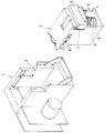
以下、この発明の実施の一形態を図に従って詳述する。図1において1は電動ステープラのドライバユニットであり、複写機の印刷面の関係から通常とは上下を逆転して、用紙テーブル(図示せず)の下にドライバユニットが配置され、用紙テーブルの上にクリンチャユニット(図示せず)が配置される。ドライバユニット1のカートリッジ収容部2へ着脱自在なステープルカートリッジ3は、背面に開口部4が形成されていて、左右両側面の後端に形成した縦方向のガイドレール部5にスライドドア6が係合している。ステープルカートリッジ3の左右両側面の上部とスライドドア6とに架設した引張りコイルバネ7により、スライドドア6は上方へ引上げられている。また、ステープルカートリッジ3の内部には後述する圧力板が内蔵されており、圧力板は内底面に設置した圧縮コイルバネ8により上方へ押し上げられている。スライドドア6は、前面(カートリッジ内部側の面)の中央下端部に溝(図示せず)が形成されていて、圧力板の後端部は溝の位置まで突出しており、図2に示すようにスライドドア6を下方へ押し下げると、圧力板9の後端部が溝に係合して図のように圧力板9も同時に下降する。
【0009】
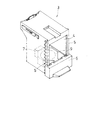
図3はステープルカートリッジ3とリフィル用の紙製ステープルパック31であり、ステープルパック31には所定枚数のステープルシート32が積重ねて収容されている。ステープルパック31は図において下面と上面前部及び背面に窓が形成されていて、図4に示すように、ステープルカートリッジ3へステープルパック31を挿入後にスライドドア6の押し下げを解除すると、前述した圧力板9は下面の窓内に入ってステープルシート32を上方へ押圧し、ステープルカートリッジ3内にある送り爪がステープルシート32の上面前部に接触する。スライドドア6は引張りコイルバネ7に付勢されて初期位置へ上昇し、ステープルパック31の背面がカバーされる。
【0010】
図5はステープルカートリッジ3をドライバユニット1へ装着した状態を示している。ステープルカートリッジ3は、天板部10の下面に板バネ11を前方斜め下へ向けて取付け、板バネ11の先端にステープルガイド12が取付けられている。ステープルガイド12の上端はステープルカートリッジ3の上面と略同一高さにあり、ステープルカートリッジ3をドライバユニット1へ装着した状態において、ステープルガイド12はドライバユニット1に設けた前方のフェースプレート21と対峙し、フェースプレート21とステープルガイド12との間の通路をステープルとドライバ22とが通過する。
【0011】
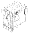
ステープルカートリッジ3の天板部10の下には前後へスライド自在なスライダ13が設けられており、スライダ13の前部に板バネ14を後方斜め下に向けて取付け、板バネ14の先端部に送り爪15を取付けてある。スライダ13の上面には横方向へ延びるアーム16が取付けられていて、図6に示すように、アーム16の左右両端部はステープルカートリッジ3に形成した溝17を通じて外側へ突出し、ドライバユニット1のリンクレバー23がアーム16を後方へ押してスライダ13を待機位置へ後退させている。24はステープル送りカム、25はステープル送りカムフォロワ、26はリンクレバー23を前方へ付勢している引張りコイルバネであり、ステープリング動作時にはモータによって回転駆動されるステープル送りカム24によりステープル送りカムフォロワ25を下降及び上昇させ、ステープル送りカムフォロワ25に伴ってリンクレバー23が前進及び後退することにより、ステープルカートリッジ3のスライダ13が連動して前後へ一往復運動する。図5に示すように、ステープルガイド12を取付けた板バネ11の前部は、初期状態においてスライダ13の上面よりも下降しており、スライダ13が前進するとスライダ13が板バネ11の下面にあたって板バネ11及びステープルガイド12を上方へ押し上げる。
【0012】
電動ステープラの駆動機構は、リンクレバー23の前方移動に続いてドライバ22の射出動作が行われるように構成されており、図5、図6 及び図7に示す初期状態からリンクレバー23によりスライダ13が前方へ押され、送り爪15により最上段のステープルシートを前方へ送るとともに、スライダ13が板バネ11を押してステープルガイド12を上方へ押し上げる。これにより、図8に示すようにステープルガイド12が浮上して、図5に示す用紙テーブル41の孔42内に入り、用紙テーブル41上の紙(図示せず)の下面に接触する。これと同時に上方のクリンチャユニット(図示せず)が下降して紙を押さえ、フォーミングプレート27が上昇してステープルSを門形にフォーミングする。
【0013】
そして、図9に示すようにステープルSのクラウン部を支持している中央のアンビル28及びその下方にあるドライバ(図示せず)が図8の状態からさらに上昇してステープルSを紙に打込む。その後にフォーミングプレート27とドライバとアンビル28が下降し、リンクレバー22によってスライダ13が初期位置へ後退され、ステープルガイド12を取付けた板バネ11が下がり、ステープルガイド12が用紙テーブル41の孔42から下方へ退避する。
【0014】
ステープルガイドの上下位置が一定で孔内から下降しない従来の電動ステープラを送り機構により横移動させる場合は、複数のステープリング位置を結ぶ長孔を形成して電動ステープラの移動を可能にする必要があるが、本発明のステープルカートリッジによれば、用紙テーブル41の複数のステープリング位置にのみ所要の寸法の孔42を形成しておけばよく、複写機構部から用紙テーブル上に送られる紙が長孔に引っ掛かる虞が解消される。また、スライダ13へ板バネ14を介して送り爪15を取付けているので、先頭のステープルがフェースプレートに当たって停止すると、板バネ14が撓んで送り爪15がステープルシートから外れ、スライダ13及び送り爪15が前進する。したがって、最上段のステープルシートのステープル数が少なくなったときに、送り爪15が初期位置へ後退して二段目のステープルシートに係合したとしても、前進行程において送り爪15が二段目のステープルシートに係合してスライダ13がロックすることがなく、スライダ13の移動ストロークは常に一定でステープルガイド12を確実に上昇させることができる。
【0015】
尚、この発明は上記の実施形態に限定するものではなく、この発明の技術的範囲内において種々の改変が可能であり、この発明がそれらの改変されたものに及ぶことは当然である。
【0016】
【発明の効果】
以上説明したように、本発明のステープルカートリッジは、ステープルの射出姿勢を規制するステープルガイドを送り爪と連動させ、射出時にステープルガイドが用紙テーブルの孔へ進入して紙に接触し、射出後に用紙テーブルの孔から出るように構成したので、一個のステープラユニットを送り機構により移動して紙の複数箇所を綴じる移動式電動ステープラを構成するにあたって用紙テーブルに長孔を設ける必要がなくなる。よって、従来の移動式電動ステープラの如く紙の端部が長孔内に入って紙送りに支障をきたす虞を解消でき、安定性が向上する。
【図面の簡単な説明】
【図1】本発明の実施の一形態を示し、ステープルカートリッジと電動ステープラの斜視図。
【図2】ステープルカートリッジを示し、スライドドアを開けた状態の斜視図。
【図3】電動ステープラのドライバユニットへステープルカートリッジを装着した状態の斜視図。
【図4】ステープルカートリッジへステープルを装填した状態を示す斜視図。
【図5】電動ステープラのドライバユニットへステープルカートリッジを装着した状態の側面断面図。
【図6】ステープルカートリッジとドライバユニットのステープル送り機構の関係を示す斜視図。
【図7】ステープルカートリッジの待機状態の斜視図。
【図8】ステープルカートリッジのステープル打込み直前の状態を示す斜視図。
【図9】ステープルカートリッジのステープル打込み時の状態を示す斜視図。
【符号の説明】
3 ステープルカートリッジ
4 開口部
5 ガイドレール部
6 スライドドア
7 引張りコイルバネ
8 圧縮コイルバネ
9 圧力板
11 板バネ
12 ステープルガイド
13 スライダ
14 板バネ
15 送り爪
16 アーム
17 溝
41 用紙テーブル
42 孔[0001]
BACKGROUND OF THE INVENTION
The present invention relates to a staple cartridge used in an electric stapler, and more particularly to a staple guide and a staple feeding claw of a staple cartridge.
[0002]
[Prior art and problems to be solved by the invention]
There are two types of copiers with built-in electric staplers: one that binds a plurality of paper locations simultaneously with a plurality of electric staplers, and one that binds a plurality of paper locations in sequence by moving one electric stapler with a feeding mechanism. In addition, for the sake of collation, in a copying machine configured to be stacked on a paper table with the paper copy side facing down, the electric stapler driver unit is placed on the paper to pass the staples from the bottom to the top of the paper. The clincher unit is placed on the paper table. The staple guide of the driver unit enters the hole formed in the paper table from below and comes into contact with the paper surface. The upper clincher unit descends and sandwiches the paper on the paper table together with the staple guide. The leg is bent by the clincher.
[0003]
In this way, in order to sandwich the paper on the paper table between the staple guide and the clincher unit of the driver unit, the staple guide has entered the hole of the paper table, and the copying is performed by moving one electric stapler laterally by the feeding mechanism. In the machine, a long slot in the horizontal direction is formed in the paper table, and the staple guide of the driver unit moves in the long hole. For this reason, when the paper is fed to the paper table through the copying process, the leading edge of the paper may be caught in the long hole of the paper table, and paper feeding failure may occur. In addition, since the formation of the long hole in the paper table causes a decrease in the bending strength of the paper table, it is desirable that the size of the hole is as small as possible.
[0004]
Therefore, a technical problem to be solved in order to enable the electric stapler to move without forming a long hole in the paper table arises, and the present invention aims to solve the above problem.
[0005]
[Means for Solving the Problems]
The present invention is to propose in order to achieve the above object, in a staple cartridge (3) used in the electric stapler, projecting the front end portion of the staple cartridge (3) from the staple cartridge (3) in the staple injection direction A flexible staple guide (12) and an interlocking mechanism that links the electric stapler drive mechanism and the staple guide (12) are provided so that the staple guide (12) protrudes from the staple cartridge (3) in the staple ejection direction during stapling operation. The staple cartridge is configured such that the staple guide (12) is retracted into the staple cartridge (3) when the stapling operation is completed.
[0006]
The interlocking mechanism includes a staple guide (12) attached to the staple cartridge (3) via a leaf spring (11), and a slider (13) reciprocated back and forth by the electric stapler driving mechanism. (13) press the leaf spring (11) which is in the movement path of the slider (13) during the forward movement, provides a staple cartridge for projecting the staple guide (12) from the staple cartridge (3) in the staple firing direction Is.
[0007]
Further, the feeding claw (15) is attached to the slider (13) via the leaf spring (14) , and the feeding claw (15) is engaged with the staple sheet (32) or on the staple sheet (32) according to the feeding load. A staple cartridge configured to slide is provided.
[0008]
DETAILED DESCRIPTION OF THE INVENTION
Hereinafter, an embodiment of the present invention will be described in detail with reference to the drawings. In FIG. 1,
[0009]
FIG. 3 shows a
[0010]
FIG. 5 shows a state in which the
[0011]
A
[0012]
The drive mechanism of the electric stapler is configured such that the injection operation of the driver 22 is performed following the forward movement of the
[0013]
Then, as shown in FIG. 9, the
[0014]
When a conventional electric stapler in which the vertical position of the staple guide is constant and does not descend from the hole is moved laterally by the feed mechanism, it is necessary to form a long hole connecting a plurality of stapling positions to enable the movement of the electric stapler. However, according to the staple cartridge of the present invention, it is only necessary to form
[0015]
The present invention is not limited to the above-described embodiment, and various modifications are possible within the technical scope of the present invention, and it is natural that the present invention extends to those modifications.
[0016]
【The invention's effect】
As described above, in the staple cartridge of the present invention, the staple guide that regulates the ejection posture of the staple is interlocked with the feed claw, the staple guide enters the hole of the paper table at the time of ejection, contacts the paper, and the paper after ejection. Since it is configured so as to come out from the hole in the table, it is not necessary to provide a long hole in the paper table when configuring a movable electric stapler in which a single stapler unit is moved by a feeding mechanism to bind a plurality of paper locations. Therefore, the possibility that the end of the paper enters the slot and interferes with the paper feeding as in the conventional mobile electric stapler can be eliminated, and the stability is improved.
[Brief description of the drawings]
FIG. 1 is a perspective view of a staple cartridge and an electric stapler according to an embodiment of the present invention.
FIG. 2 is a perspective view showing a staple cartridge with a slide door opened.
FIG. 3 is a perspective view of a state where a staple cartridge is mounted on a driver unit of an electric stapler.
FIG. 4 is a perspective view illustrating a state in which staples are loaded into a staple cartridge.
FIG. 5 is a side cross-sectional view of a state where a staple cartridge is mounted on a driver unit of an electric stapler.
FIG. 6 is a perspective view showing a relationship between a staple cartridge and a staple feeding mechanism of a driver unit.
FIG. 7 is a perspective view of a staple cartridge in a standby state.
FIG. 8 is a perspective view showing a state of the staple cartridge just before staple driving.
FIG. 9 is a perspective view showing a state when a staple is driven in a staple cartridge.
[Explanation of symbols]
3 Staple cartridge
4 opening
5 Guide rail
6 Sliding door
7 Tension coil spring
8 Compression coil spring
9 Pressure plate
11 Leaf spring
12 Staple guide
13 Slider
14 Leaf spring
15 Feeding claw
16 arms
17 groove
41 Paper table
42 holes
Claims (3)
Priority Applications (14)
| Application Number | Priority Date | Filing Date | Title |
|---|---|---|---|
| JP2001363321A JP4096552B2 (en) | 2001-11-28 | 2001-11-28 | Staple cartridge |
| DE60238214T DE60238214D1 (en) | 2001-11-15 | 2002-11-15 | STAPLE MAGAZINE |
| CNB028225333A CN100423916C (en) | 2001-11-15 | 2002-11-15 | Staple cartridge |
| EP10001853A EP2189261B1 (en) | 2001-11-15 | 2002-11-15 | Staple cartridge |
| TW091133492A TWI224540B (en) | 2001-11-15 | 2002-11-15 | Staple cartridge |
| PCT/JP2002/011957 WO2003041922A1 (en) | 2001-11-15 | 2002-11-15 | Staple cartridge |
| AT10001853T ATE526132T1 (en) | 2001-11-15 | 2002-11-15 | BRACKET MAGAZINE |
| AT02803121T ATE486703T1 (en) | 2001-11-15 | 2002-11-15 | BRACKET MAGAZINE |
| KR1020047006950A KR100804343B1 (en) | 2001-11-15 | 2002-11-15 | Staple cartridge |
| AT10001854T ATE542653T1 (en) | 2001-11-15 | 2002-11-15 | BRACKET MAGAZINE |
| EP02803121A EP1454722B1 (en) | 2001-11-15 | 2002-11-15 | Staple cartridge |
| US10/495,551 US7597228B2 (en) | 2001-11-15 | 2002-11-15 | Staple cartridge |
| EP10001854A EP2181817B1 (en) | 2001-11-15 | 2002-11-15 | Staple cartridge |
| US12/453,157 US7721929B2 (en) | 2001-11-15 | 2009-04-30 | Staple cartridge |
Applications Claiming Priority (1)
| Application Number | Priority Date | Filing Date | Title |
|---|---|---|---|
| JP2001363321A JP4096552B2 (en) | 2001-11-28 | 2001-11-28 | Staple cartridge |
Publications (2)
| Publication Number | Publication Date |
|---|---|
| JP2003165069A JP2003165069A (en) | 2003-06-10 |
| JP4096552B2 true JP4096552B2 (en) | 2008-06-04 |
Family
ID=19173682
Family Applications (1)
| Application Number | Title | Priority Date | Filing Date |
|---|---|---|---|
| JP2001363321A Expired - Fee Related JP4096552B2 (en) | 2001-11-15 | 2001-11-28 | Staple cartridge |
Country Status (1)
| Country | Link |
|---|---|
| JP (1) | JP4096552B2 (en) |
-
2001
- 2001-11-28 JP JP2001363321A patent/JP4096552B2/en not_active Expired - Fee Related
Also Published As
| Publication number | Publication date |
|---|---|
| JP2003165069A (en) | 2003-06-10 |
Similar Documents
| Publication | Publication Date | Title |
|---|---|---|
| CN100382945C (en) | electric stapler | |
| US5273199A (en) | Staple cartridge | |
| US8251272B2 (en) | Stapler | |
| US5150826A (en) | Apparatus for forming and driving staples | |
| JPH0585358B2 (en) | ||
| US7900804B2 (en) | Stapler and staple cartridge | |
| JP4300397B2 (en) | Staple leg guide mechanism | |
| CN100423916C (en) | Staple cartridge | |
| JP4465832B2 (en) | Electric stapler | |
| JP4096552B2 (en) | Staple cartridge | |
| EP1652627B1 (en) | Electrically driven stapler | |
| JP4036215B2 (en) | Electric stapler | |
| JP4232716B2 (en) | Stapler cartridge | |
| JPH0111426Y2 (en) | ||
| CN100418705C (en) | stapler | |
| JP4292739B2 (en) | Electric stapler | |
| JP4089211B2 (en) | Staple cartridge | |
| JP2003170404A (en) | Electric stapler | |
| JP3518428B2 (en) | Electric stapler | |
| JP3879593B2 (en) | Self-priming detection mechanism in electric stapler | |
| JP3855263B2 (en) | Stapler | |
| JP2005014416A (en) | Staple feeding mechanism of electric stapler | |
| JPH09155762A (en) | Motor-driven stapler | |
| HK1109362A1 (en) | Stapler with adapter | |
| HK1109362B (en) | Stapler with adapter |
Legal Events
| Date | Code | Title | Description |
|---|---|---|---|
| A621 | Written request for application examination |
Free format text: JAPANESE INTERMEDIATE CODE: A621 Effective date: 20041102 |
|
| A131 | Notification of reasons for refusal |
Free format text: JAPANESE INTERMEDIATE CODE: A131 Effective date: 20071219 |
|
| A521 | Written amendment |
Free format text: JAPANESE INTERMEDIATE CODE: A523 Effective date: 20080122 |
|
| TRDD | Decision of grant or rejection written | ||
| A01 | Written decision to grant a patent or to grant a registration (utility model) |
Free format text: JAPANESE INTERMEDIATE CODE: A01 Effective date: 20080219 |
|
| A61 | First payment of annual fees (during grant procedure) |
Free format text: JAPANESE INTERMEDIATE CODE: A61 Effective date: 20080303 |
|
| R150 | Certificate of patent or registration of utility model |
Ref document number: 4096552 Country of ref document: JP Free format text: JAPANESE INTERMEDIATE CODE: R150 Free format text: JAPANESE INTERMEDIATE CODE: R150 |
|
| FPAY | Renewal fee payment (event date is renewal date of database) |
Free format text: PAYMENT UNTIL: 20110321 Year of fee payment: 3 |
|
| FPAY | Renewal fee payment (event date is renewal date of database) |
Free format text: PAYMENT UNTIL: 20110321 Year of fee payment: 3 |
|
| FPAY | Renewal fee payment (event date is renewal date of database) |
Free format text: PAYMENT UNTIL: 20120321 Year of fee payment: 4 |
|
| FPAY | Renewal fee payment (event date is renewal date of database) |
Free format text: PAYMENT UNTIL: 20130321 Year of fee payment: 5 |
|
| FPAY | Renewal fee payment (event date is renewal date of database) |
Free format text: PAYMENT UNTIL: 20130321 Year of fee payment: 5 |
|
| FPAY | Renewal fee payment (event date is renewal date of database) |
Free format text: PAYMENT UNTIL: 20140321 Year of fee payment: 6 |
|
| LAPS | Cancellation because of no payment of annual fees |