JP4094805B2 - Image display device and projection-type image display device - Google Patents
Image display device and projection-type image display device Download PDFInfo
- Publication number
- JP4094805B2 JP4094805B2 JP2000319881A JP2000319881A JP4094805B2 JP 4094805 B2 JP4094805 B2 JP 4094805B2 JP 2000319881 A JP2000319881 A JP 2000319881A JP 2000319881 A JP2000319881 A JP 2000319881A JP 4094805 B2 JP4094805 B2 JP 4094805B2
- Authority
- JP
- Japan
- Prior art keywords
- lens
- light
- image display
- display device
- illumination spot
- Prior art date
- Legal status (The legal status is an assumption and is not a legal conclusion. Google has not performed a legal analysis and makes no representation as to the accuracy of the status listed.)
- Expired - Fee Related
Links
Images


Landscapes
- Microscoopes, Condenser (AREA)
- Mechanical Light Control Or Optical Switches (AREA)
- Projection Apparatus (AREA)
- Video Image Reproduction Devices For Color Tv Systems (AREA)
Description
【0001】
【発明の属する技術分野】
本発明は、赤、青、緑よりなる三原色の照明光を高速に切り替えて供給する照明光学系と、これに同期させて三原色の各色原画像を順次表示する空間光変調素子とを組み合わせてなる画像表示装置、及びこの画像表示装置から出射する光を投写レンズに導き、空間光変調素子の表示画像を拡大投影する投写型画像表示装置に関する。
【0002】
【従来の技術】
AV機器やプレゼンテーション用あるいはワークステーション用の画像表示装置や大画面プロジェクタ(投写型画像表示装置)に用いられる空間光変調素子(SLM)には、受光型表示素子である液晶パネルや反射型表示素子であるDMD素子(デジタルマイクロミラー素子)がよく用いられる。
【0003】
ところで画像表示装置などに用いられる液晶パネルは、それ自体は白黒画像を表示するのであるが、外部から供給される映像信号に応じたカラー画像を構成する為に、R(赤)、G(緑)、B(青)の各色原画像を高速に時系列的に切替えて表示するように構成されている。その為に、応答速度の速い液晶材料、例えば強誘電性液晶が用いられる。この強誘電性液晶は、一般には白黒の2値表示用途として知られるが、白表示のOn期間を制御することで、いわゆるパルス幅(時間軸)変調を用いた階調表示を行えるのでR、G、Bの三原色の各色原画像を形成することが可能となり、ひいてはフルカラーの表示を実現できるように構成されている。また画像表示装置などに用いられるDMD素子は微小なミラー構造を2次元状に配列し、入射する光の反射される方向をOn/Off制御し、空間的に光を変調して光学像を形成するように構成されている。
【0004】
これら液晶パネルやDMD素子を用いた画像表示装置や投写型画像表示装置においてカラー画像を構成する方法としては、赤、青、緑よりなる三原色の各色原画像に対応させて3枚の表示素子を用いる方式や、1枚の表示素子上にモザイク状のカラーフィルタを形成してRGBのトリオ画素を用いる方式、また上述したように白黒表示の空間光変調素子を1枚用いてR(赤)、G(緑)、B(青)の各色原画像を時系列表示し、各色原画像に同期させて照明光の色を切り替える方式である、一般に色順次表示方式と呼ばれる方法がある。
【0005】
以下、この色順次表示方式による空間光変調素子を用いた画像表示装置について説明する。
図15は色順次表示方式による空間光変調素子を採用した従来の画像表示装置の概略図である。ランプ(ここでは図示せず。)は発光体101を形成し、発光体101は白色光を放射する光源となる。凹面鏡102は発光体101の放射する白色光を集光し、回転型色フィルタ103上に照明スポット104を形成する。このため、凹面鏡102の反射面を楕円面形状とし、第1焦点に発光体101を配置して、第2焦点に相当する集光位置に、回転型色フィルタ103が配置されている。尚、ここでは特に図示はしないが、放物面鏡を用いて平行に進行する光束を形成し、集光レンズを追加して光束を焦平面に収斂させて、照明スポット104を形成してもよい。そして照明スポット104から出射する色順次照明光は、集光レンズ108により平行光となり、透過型の液晶パネル109を照明し、その結果、観察者には、カラーの表示画像が呈示される。
【0006】
このように、白色光を放射する光源を利用する画像表示装置では、白色光を高速のRGB色順次照明光に切り替える為に、上述のような回転型色フィルタが利用される。この回転型色フィルタとは、モータで駆動されて高速に回転する円周上に、赤透過、緑透過、青透過の色フィルタセグメントを適当に配列したもので、回転するこれらの色フィルタを照明光が通過する結果、高速にR→G→Bと切り替わる色順次照明光を形成するものである。
【0007】
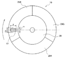
この回転型色フィルタを図面を参照しつつさらに説明する。図16は回転型色フィルタ103の構成の一例と、その上に形成された照明スポット104を示す。回転型色フィルタ103は、R、G、Bの三原色の色フィルタを正円状に組み合わせたもので、具体的には、モータ105に直結された回転支持体(ハブ)106に、赤色透過フィルタ107R、緑色透過フィルタ107G、青色透過フィルタ107B、が固着されている。そして外部からの制御信号に応じて、ハブ106に結合された赤色透過フィルタ107R、緑色透過フィルタ107G、青色透過フィルタ107B、を高速に回転させる。そしてこれらの色フィルタが接合された円周上に照明スポット17が形成され、色フィルタ29R、29G、29Bが、液晶パネル22の表示する各色原画像に合わせて、高速に回転し、表示画像に同期させて、適切な色の照明光を形成する。このようにして、各色フィルタは照明スポット104を通過する白色光について特定の波長帯域の光を取り除き、結果として高速に切り替わる色順次照明光を形成する。またこの色フィルタとして、多層膜を蒸着工法やスパッタ工法でガラス基板上に形成したダイクロイックフィルタが用いられることが多いが、このダイクロイックフィルタは、多層膜に入射する光線の入射角に依存して、透過させる光の波長帯域特性(カットオフ波長)が変化する、という特徴を有している。
【0008】
ところで回転型色フィルタ103において、異なる色のフィルタが隣接するフィルタ接合部を照明スポット104が通過する場合、何も処理をしなければ、一定の期間、所望の原色光ではなく2色が混じった照明光が形成されてしまい、正しい色の画像が呈示されなくなる。このことを防ぐ為に、色が切り替わる間の時間は空間光変調素子(液晶パネル)を黒表示とし、その間は色原画像を表示しないように休止期間を設ける必要がある。この休止期間に色フィルタに入射する照明光は有効に利用されず、呈示画像の明るさに寄与しない。また空間光変調素子では一般に、色の切り替わりに必要な期間は、色原画像の更新に必要なデータ転送期間よりもかなり長い。
【0009】
このように、空間光変調素子における、色の切り替わり期間を除いた有効な画像の表示期間の、全周期期間に対する割合を空間光変調素子の時間開口率と呼び、空間光変調素子の光利用効率を示す目安の1つとなっている。通常この時間開口率は80〜90%程度である。この時間開口率が向上するほど、明るい画像を得られる画像表示装置とすることが出来る。
【0010】
この空間光変調素子の時間開口率について、上記回転型色フィルタと液晶パネルを組み合わせた場合について、さらに説明する。
液晶パネル22は、一般にNTSC方式などのTV画像を表示する目的に用いられるので、例えばNTSC方式などのTV画像用に液晶パネル22を用いるのであれば、1秒間に60フレームのカラー画像を形成すればよい。従って、1/60秒をRGBの三原色で三分割し、即ち1/180秒毎に、R→G→B→Rのように順次三原色の各色原画像を表示するように液晶パネル22を構成する。ここで図3は液晶パネル22に表示される画像の手順を示し、n番目のフレームの画像について赤の原画像をR(n)、緑の原画像をG(n)、青の原画像をB(n)、と表している。
【0011】
回転型色フィルタ16において、隣り合う色フィルタの接合部が照明スポット17を通過する時に生じる色順次照明光は2色が混じった状態となるので、画像の表示には使用できない。このため、図3に示した場合では、1つの色原画像に与えられた実効的な表示期間τonは、その全周期期間τaから混色を避けるために設けられた休止期間を引いたものになっている。故に液晶パネルの時間開口率は、τon÷τaで表される。
【0012】
ここで、画像表示装置の画像をより明るくする為に、光源に用いるランプの電力を増加させることが考えられるが、電力を増加させることは消費電力の増加を意味し、ひいては画像表示装置内の発熱量が増加するので、この方法は好ましくない。むしろ時間開口率を向上させることの方が効果的である。
【0013】
ところで、この空間光変調素子の時間開口率は、回転型色フィルタ103上に形成される照明スポット104の大きさと、フィルタ接合部が照明スポット104を通過する円周方向の速度に依存するので、照明スポットの大きさが同じ場合、より大きな半径の回転型色フィルタを用いれば、大きな半径の回転型色フィルタの方が相対的に外周上でフィルタ接合部が照明スポットを通過する速度が速くなり、その結果空間光変調素子の時間開口率を高く出来る。また回転型色フィルタの大きさが同じ場合、照明スポットの大きさが小さい方が相対的に空間光変調素子の時間開口率を高くすることができる。
【0014】
このうち、回転型色フィルタを大型化する方法であれば空間光変調素子の時間開口率を高くできるものの、回転型色フィルタが大型となることで、装置全体の小型化が難しくなる。さらに色フィルタが高価となり、必要なモータの駆動トルクも大きくする必要があり、即ちモータが大型化し高価となる、等の新たな課題を生じるので、この方法は好ましくない。
【0015】
よって、照明スポットを小さくすることが空間光変調素子の時間開口率を高くするのに好ましい方法と言える。そして照明スポットの大きさは、画像表示装置の光源に用いる発光体の大きさと、照明スポットを形成する集光光学系の照射角によって決まる。
【0016】
まず発光体の大きさについて検討すると、発光体を小さくするほど照明スポットが小さくなることは自明である。
【0017】
次に、集光光学系の照射角について検討すると、照射角を大きくすれば、所謂、ラグランジェ−ヘルムホルツの不変量に従って、形成される像の大きさ、すなわち照明スポットの大きさを小さくできる。この場合、色フィルタに入射する光の集中角が大きくなり、より角度変化範囲の拡がった光線群に対して、色フィルタが作用する。しかし、照射角の大きい光線群に対して、従来画像表示装置の回転型色フィルタに用いられる、上述したようなダイクロイックフィルタを作用させた場合、入射角の大きい光線群については所望のカットオフ波長が得られず、本来必要でない色純度の低い光線を通過させてしまったり、逆に本来必要な色純度の高い光線の通過を阻止してしまう、という問題がある。即ち、フィルタ通過後の色光について、所望の色純度の原色光を得られない、或いは、所望の色純度を得るにはフィルタのカットオフ波長を高色純度側にシフトさせる必要が生じ、このためにフィルタの光利用効率が低くなる、ひいては画像表示装置全体の効率が低下し、呈示される画像が暗くなる、といった問題を生じるので、画像表示装置全体の効率を上げる為には、照明スポットへの光の照射角を小さくする方が好ましいと言える。
【0018】
このように、より小型で、明るく、色再現性の良好な画像表示装置を実現する為には空間光変調素子の時間開口率を向上させることが効果的であり、空間光変調素子の時間開口率を向上させる為には、発光体を小型化し、また出来るだけ小さい回転型色フィルタを用いると共に、照明スポットをできるだけ小さくし、さらに照明スポットへの光の照射角を小さくすればよい。
【0019】
【発明が解決しようとする課題】
しかし、従来用いられている、楕円面鏡や放物面鏡と集光レンズの組み合わせで照明スポットを形成する方式の場合、発光体を小型化すること、また出来るだけ小さい回転型色フィルタを用いると共に、照明スポットをできるだけ小さくし、また照明スポットへの光の照射角を小さくすること、を実現することは困難である。
【0020】
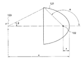
まず、照明スポットへの光の照射角について図17を参照しつつさらに検討すると、楕円面鏡121は、発光体122の放射する光を捕捉し、第2焦点近傍に照明スポット123を形成するが、ここで高い集光効率を得るには楕円面鏡の集光範囲αを大きくする必要がある。しかし集光範囲αを大きくすると照明光の照射角θが大きくなってしまう。また照明スポットを小さくするには、第2焦点までの距離xを小さくすればよいが、距離xを小さくするのに伴って照明光の照射角θが大きくなってしまう。一方、照明光の照射角θを小さくするには、集光範囲αを小さくするか、第2焦点までの距離xを大きくする必要があるが、集光範囲αを小さくすると必要な明るさをえられなくなり、また距離xを大きくすれば、照明スポットの大きさyが大きくなってしまう。
【0021】
また発光体の大きさについて検討すると、照明スポットを小さくするために発光体自体を小型化しようとしても、従来の画像表示装置の発光体に用いられるメタルハライドランプや高圧水銀灯は、発光体自体の小型化が難しい、と言う問題がある。またアーク放電を利用するランプを用いる場合では、照明スポットを小さくするためにアーク放電を形成する電極間隔を短くすることが考えられるが、これだと良好な発光特性を得られないし、ランプ寿命が極端に短くなる、アーク放電が安定しない、ランプ電流が大きくなり電源が大型化する、といった新たな問題が生じてしまう。さらに点灯時間に応じて寿命期間中に発光体の大きさが変わってしまう、という問題も生じる。これは、アーク放電を利用するランプの場合、点灯時間に応じて電極が消耗し、点灯を繰り返すと、やがて電極間のギャップが拡がってしまい、ひいては何回も点灯を繰り返すと、やがて放電アークもだんだん大きくなってしまい、ひいては照明スポットもだんだん大きくなってしまう、という問題も生じる。
【0022】
このように、回転型色フィルタ上に形成される照明スポットの大きさは、光学系が一定であれば、発光体の大きさに応じて決まるが、ランプの寿命期間に依って、電極間のギャップが徐々に大きくなり、つまり放電アークも徐々に大きくなってしまい、つまり発光体も徐々に大きくなってしまい、その結果点灯を繰り返すに従って徐々に照明スポットが大きくなる、という問題が生じる。
【0023】
さらに、ランプを大量生産する場合、全てのランプの電極間のギャップを精度良く一定に管理することが比較的難しく、電極間のギャップ距離にばらつきが生じてしうまうので、製品間の誤差が大きくなってしまう、という問題も生じる。つまり、上述のばらつきをランプ個々に測定し、個々のランプに対応して製品毎に空間光変調素子の時間開口率を設定することは極めて煩雑で難しい。従って、ばらつきの中で可能性のある最も大きな発光体の大きさに合わせて空間光変調素子の時間開口率を決める必要があるが、これは非現実的である。
【0024】
さらに画像表示装置のセット寿命期間の間に不必要な混色を発生させないためには、予めランプ寿命経過後の発光体により生じる照明スポットがどれだけ大きくなるか、その最大の大きさを想定し、想定された照明スポットの大きさにに合わせて、空間光変調素子の時間開口率を定める必要があるが、このように空間光変調素子の時間開口率を定めてしまうと、画像表示装置を使用開始した直後の、即ち初期のランプを用いる場合、最低限必要な空間光変調素子の時間開口率をも得られなくなるので、使用開始直後は必要な明るさを得ることができない画像表示装置となってしまい、やはり問題である。
【0025】
そこで本発明はこのような問題点に鑑みて為されたものであり、その目的は、装置を大型化すること無く、また発光体の大きさや状態に関係なく空間光変調素子の時間開口率を高く設定することを可能とすることにより、色純度と効率の高い色順次表示をすることを可能とした画像表示装置、及びこの画像表示装置を用いた投写型画像表示装置を提供することである。
【0026】
【課題を解決するための手段】
上記課題を達成するため、本発明の請求項1に記載の画像表示装置では、白色光を放射する光源と、前記光源の放射光を集めて略単一の光束を形成する集光手段と、前記集光手段によって形成された光束を用いて矩形の照明スポットを形成する第1照明系と、前記照明スポット近傍に配置されて前記白色光を赤、青、緑の各色光に順次切り替える円形状の回転型色フィルタと、赤、青、緑の各色原画像を時系列的に切替えて表示することに用いる空間光変調素子と、前記回転型色フィルタを通過した光を集光して前記空間光変調素子を照明する照明光を形成する第2照明系と、を備えた画像表示装置であって、前記第1照明系は、前記回転型色フィルタを通過する光線群の主光線を略光軸に平行に進行させる補助レンズを備え、前記空間光変調素子の表示領域のアスペクト比に略等しいアスペクト比を有する前記照明スポットを形成し、前記第2照明系は、前記回転型色フィルタを通過した光線群を収束させる入力部収束レンズを備え、前記回転型色フィルタによって形成される赤、青、緑の各色光の出力と前記空間光変調素子の表示とを同期させて、前記照明スポットと前記空間光変調素子とを略共役の関係とさせ、前記照明スポットの短辺方向と、前記回転型色フィルタの円周方向(接線方向)とを略一致させ、前記補助レンズと前記入力部収束レンズとを前記回転型色フィルタの前後に配置させるとともに、前記第1照明系は、前記照明スポットを形成する射出瞳の近傍に前記光源の実像を形成すると共に、前記射出瞳の近傍に開口絞りを備えた、ことを特徴とする。
【0027】
本発明の請求項2に記載の画像表示装置では、請求項1に記載の画像表示装置において、前記第1照明系は、前記照明スポットを光学インテグレータ素子で形成する、ことを特徴とする。
【0028】
本発明の請求項3に記載の画像表示装置では、請求項2に記載の画像表示装置において、前記第1照明系は、前記光学インテグレータ素子が、複数のレンズを二次元状に配列してなる、第1レンズアレイと第2レンズアレイとで構成され、前記第1レンズアレイは、前記集光手段から出射する光束を複数の部分光束に分割すると共に、前記部分光束を前記第1レンズアレイに対応する前記第2レンズアレイの開口近傍に収斂させ、前記第2レンズアレイは、対応する前記第1レンズアレイから出射する前記複数の部分光束を回転型色フィルタの近傍に導くと共にこれらを重畳させて照明スポットを形成する、ことを特徴とする。
【0030】
本発明の請求項4に記載の画像表示装置では、請求項1ないし請求項3のいずれか1項に記載した画像表示装置において、前記第2照明系は、前記回転型色フィルタ近傍に配置される入力部収束レンズと、前記空間光変調素子近傍に配置される出力部収束レンズと、前記入力部収束レンズと前記出力部収束レンズの間の光路に配置される中央部収束レンズと、を備え、前記入力部収束レンズは前記入力部収束レンズに入射する光を前記中央部収束レンズの開口中心近傍に収斂させ、前記中央部収束レンズは前記入力部収束レンズの主平面近傍の物体の実像を前記出力部収束レンズの主平面近傍に形成し、前記出力部収束レンズは前記中央部収束レンズから出射する光を前記空間光変調素子に有効に導く、ことを特徴とする。
【0031】
本発明の請求項5に記載の投写型画像表示装置では、請求項1ないし請求項4のいずれか1項に記載の画像表示装置を用いた投写型画像表示装置であって、前記空間光変調素子上に表示される光学像を投影する投写レンズを備えた、ことを特徴とする。
【0036】
【発明の実施の形態】
以下、本発明の実施の形態について図面を参照しながら説明する。尚、ここで示す実施の形態はあくまでも一例であって、必すしもこの実施の形態に限定されるものではない。
【0037】
(実施の形態1)
まず、本発明の請求項1及び請求項4に対応する画像表示装置を第1の実施の形態として、図面を参照しつつ説明する。
図1は本実施の形態1に係る画像表示装置Aの概略構成図である。この画像表示装置Aは、発光体10と、放物面鏡11と、アナモフィックレンズ13、14と、補助レンズ15と、円形状の回転型色フィルタ16と、リレーレンズ系21と、液晶パネル22と、を備えている。
【0038】
発光体10は、ここでは図示しないランプによって形成される白色光を放射する光源であり、放物面鏡11は発光体10の放射する白色光を集光して、光軸12に沿っておよそ平行に進行する光束を形成する。
【0039】
2つのアナモフィックレンズ13、14は、これらに入射する白色光を集光して、回転型色フィルタ16の上に矩形の照明スポット17を形成する。また2つのアナモフィックレンズ13、14は、異なる曲率半径を有し、適当なアスペクト比の矩形の照明スポットを形成する。尚、2つのアナモフィックレンズ13、14の曲率方向は直交している。
【0040】
補助レンズ15は、回転型色フィルタ16に入射する光線が、光軸12と平行に近くなるようにするために用いる。尚、これらアナモフィックレンズ13、14、補助レンズ15によって第1照明系が構成され、この第1照明系によって矩形の照明スポット17が回転型色フィルタ16上に形成される。照明スポット17については後述する。
【0041】
回転型色フィルタ16は、従来の技術の説明において図16を参照しつつ説明した回転型色フィルタ106と同様のものであって、図2に示すように、モータ23に直結された回転支持体(ハブ)28に、赤の透過型ダイクロイックフィルタ29R、緑の透過型ダイクロイックフィルタ29G、青の透過型ダイクロイックフィルタ29B、が固着されている。これら各フィルタ29R、29G、29Bは、やはり従来の技術で説明したように、透明のガラス基材上にダイクロイック多層膜を蒸着やスパッタ工法で形成したものを用いているが、必ずしもこのようにして製作されたフィルタに限定されるものではない。
【0042】
第2照明系であるリレーレンズ系21は、入力部収束レンズ18、中央部収束レンズ19、出力部収束レンズ20、から構成される。入力部収束レンズ18は、回転型色フィルタ16上の照明スポット17から出射した光を収斂させて、中央部収束レンズ19の開口上に照明スポット17に対する射出瞳の実像を形成する。尚、この射出瞳は、具体的にはアナモフィックレンズ13、14近傍に位置している。中央部収束レンズ19は、入力部収束レンズ18の主平面近傍の実像を出力部収束レンズ20の開口近傍に形成し、入力部収束レンズ18から出射して中央部収束レンズ19に到達する光を出力部収束レンズ20に導く。出力部収束レンズ20は、中央部収束レンズ19から出射する光を光軸12に略平行に進行する光束とし、この光束が液晶パネル22を照明する。そして液晶パネル22は、従来の技術で説明した公知の液晶パネルが用いられる。
【0043】
これらの部材により構成される画像表示装置Aでは、発光体10の放射する光は放物面鏡11により集光され、アナモフィックレンズ13、14と、補助レンズ15とを経て、回転型色フィルタ16上の照明スポット17に到達し、入力部収束レンズ18と中央部収束レンズ19と出力部収束レンズ20と、よりなるリレーレンズ系21を経由して、最終的に液晶パネル22に到達する。そしてリレーレンズ系21は、回転型色フィルタ16によって形成される赤、青、緑の各色光と液晶パネル22の表示とを同期させることによって、照明スポット17と液晶パネル22とを略共役の関係とする。このようにして、発光体10の放射する光の大部分が液晶パネル22を有効に照明する。
【0044】
ここで、照明スポット17と液晶パネル22との関係を見ると、回転型色フィルタ16上に照明スポット17が形成され、色フィルタ29R、29G、29Bが、液晶パネル22の表示する各色原画像に合わせて高速に回転し、表示画像に同期させて適切な色の照明光を形成し、この照明光が上述の通り液晶パネル22を照明しているのであるが、本実施の形態における画像表示装置Aでは、より明るい画像を得るために、即ち液晶パネル22の時間開口率を出来るだけ高い効率とするために、下記の工夫をしている。
【0045】
画像表示装置AをデジタルTV用途のワイド画面に対応させたものとした場合、デジタルTV用ワイド画面では正方形の画素を水平方向に854個、垂直方向に480個配列してあるので、液晶パネル22の表示領域のアスペクト比(水平方向の長さと垂直方向の長さの比)は、16:9とすればよい。そして画像表示装置Aは、リレーレンズ系21の作用により、照明スポット17と液晶パネル22の表示領域とをおよそ共役の関係としているので、照明スポット17は、液晶パネル22の表示領域の形状に合わせて16:9アスペクト比の矩形形状にする。そして、画像表示装置Aでは曲率方向の直交する2つのアナモフィックレンズ13、14を用いて、これらのレンズに入射する光を適切に収束させることで、照明スポット17を16:9のアスペクト比を有する矩形形状にしている。そして回転型色フィルタ16は、図2に示すように、その回転する円周方向(接線方向)と、形成される矩形の照明スポット17の短辺(x)方向とが同じ方向になるように配置する。このようにすれば、円形の照明スポットを形成する場合、矩形の照明スポットを形成してその短辺方向と円周方向を一致させる場合、色フィルタの接合部に照明スポットが当たる時間を短く出来るので、液晶パネル22の時間開口率を高くする。つまり、矩形の照明スポット17の短辺(x)が短かければ、表示素子における色の切り替え時の休止期間を相対的に短くできるので、液晶パネル22の時間開口率を高くできる、ということである。
【0046】
ちなみに、同じ面積を有する正円と長方形とを比較すると、正円の直径がDであるならば、長方形の短辺の長さxは、その長辺の長さをyとして、
x=(π/4)・(D/y)・D
で表されるが、π/4、D/yは、いずれも1より小さいことは自明である。
【0047】
従って、短辺の長さxは、直径Dよりも小さく、照明スポットの面積が同じであるならば、矩形のスポットを形成した方が、円形のスポットとした場合よりも照明スポットが色フィルタの接合部を通過する時間を短くすることが出来るので、液晶パネル22の時間開口率を高くすることが出来る。
【0048】
尚、上述したアスペクト比と異なるアスペクト比を有する場合、例えば現在流通している普通のブラウン管TVの表示サイズである4:3のアスペクト比を有する表示素子等の場合であっても、上述同様の作用及び効果が得られる。
このように本実施の形態に係る画像表示装置Aは、液晶パネル22の時間開口率を高くすることにより、高い色純度を実現できる画面表示装置としている。
【0049】
(実施の形態2)
次に、本発明の請求項2及び請求項3に対応する画像表示装置Bを第2の実施の形態として図面を参照しつつ説明する。
図4は画像表示装置Bの概略構成図であるが、図1に示した画像表示装置Aと同一の部材については同一の番号を附し、その説明については省略する。
【0050】
この画像表示装置Bにおいて、照明スポット17は液晶パネル22の表示領域と相似のおよそ16:9アスペクト比の矩形開口を有しているものとするが、これに限定されるものではない。そしてこれを通過する光束は、前述の画像表示装置Aと同様に、リレーレンズ系21により液晶パネル22まで導かれて液晶パネル22の表示領域を照明する。そして照明スポット17と液晶パネル22は共役の関係となっている。尚、色順次表示される液晶パネル22と回転型色フィルタ16の関係は画像表示装置Aにおいて説明したものと同様であり、16:9アスペクト比の矩形の照明スポット17は、同様に短辺を回転型色フィルタの回転する円周方向と合致させることによって液晶パネル22の時間開口率を改善している。
【0051】
そして本実施の形態2における画像表示装置Bでは、より明るく色純度の優れた画像を得るために、略均一な明るさ分布を有する照明スポットを得られるように、第1照明系に光学インテグレータ素子を導入している。以下、光学インテグレータ素子について説明する。
【0052】
画像表示装置Bの回転型色フィルタ16として用いられているダイクロイックフィルタには、照射光の照射角が広範囲でばらつくとカットオフ波長が大きくシフトしてしまう性質があるので、より多くの光量を通過させようとすると色純度が低下し、高い色純度を実現しようとすると必要な波長帯域の光までカットしてしまう。この問題点を改善する為には、第1照明系に光学インテグレータ素子を導入することで、ダイクロイックフィルタへの照射光の照射角を平均化すればよい。
【0053】
そこで、照明スポット17を形成する第1照明系の部分に光学的に積分作用のある光学インテグレータ(積分器)素子を導入すると、照明光が回転型色フィルタ16上の照明スポット17に至る時に、回転型色フィルタ16への照明光の照射角が平均化されて、明るさ分布が略均一となる。つまり特に照射角の大きな光が生じず、ダイクロイックフィルタへの照射光の照射角が平均化されることになる。
【0054】
更に、第1照明系に光学インテグレータ素子を導入することで照明スポット17の明るさ分布を略均一性とすることにより、これと共役の関係となる液晶パネル22を照明する光の明るさ分布も略均一となって、即ち明るさむらの少ない画像表示を実現できる。
【0055】
本実施の形態2では、光学インテグレータ素子としてレンズアレイを用いており、以下、レンズアレイ及びこのレンズアレイを用いた画像表示装置Bについてさらに説明するが、光学インテグレータ素子としてレンズアレイ以外のものを用いても構わない。
【0056】
図4に示すように、画像表示装置Bにおける第1照明系は、第1レンズアレイ30、第2レンズアレイ32、収束レンズ34、及び補助レンズ35によって構成されており、これらは放物面鏡11の出射光束に対して配置されている。
【0057】
図5に示すように、第1レンズアレイ30は、液晶パネル22の表示領域と相似の16:9アスペクト比の矩形開口を有する第1レンズ31を二次元状に配列することにより構成されている。第1レンズ31は、放物面鏡11から出射する円形の光束断面(図中破線36で示す円形)である正円領域に近似するように配列する。尚、第1レンズ31の個数と配列方法は特に図示したものに限定はされない。そして図6に示すように、第2レンズアレイ32は、第2レンズ33を第1レンズ31と同様に配列して構成する。
【0058】
ここで、第1レンズアレイ30と第2レンズアレイ32の動作について説明する。第1レンズアレイ30は、比較的照明むらの大きい放物面鏡11の出射光束を、第1レンズ31によって複数の部分光束に分割する。分割される部分光束の本数は第1レンズ31の個数と等しい。これら部分光束は、明るさのむらが少なくなっている。
【0059】
第1レンズ31により分割された部分光束は、それぞれ第1レンズ31に対応する第2レンズ33(例えば第1レンズ31aには第2レンズ33aが対応している。)の開口上に導かれて収斂される。第2レンズ33は、入射した部分光束に適当な倍率を与えて照明スポット17に向けて照射することにより、第1レンズ31の矩形開口と照明スポット17とを互いに共役の関係とする。
【0060】
このようにして、これら第1レンズアレイ30と、第2レンズアレイ32とは光学的なインテグレータ(積分器)素子として作用し、むらの少ない均一な明るさ分布の照明スポット17を形成するのである。
【0061】
尚、収束レンズ34は、個々の第2レンズ33から出射する光束を重畳させた光線を補助レンズ35を経て照明スポット17上に送るものである。また、補助レンズ35は、照明スポット17に至る光線が光軸12と略平行になるようにするものである。
【0062】
このように第1照明系を構成することで、従来の場合に比べてどれだけ回転型色フィルタ16への照射光の入射角を小さいものとしているか、即ちどれだけ効果的であるか、を具体例を参照しつつさらに説明する。尚、以下の説明において、長さが2mmで直径が1mmの円筒形に近い発光体の側面から放射される光について、従来の、楕円面鏡を用いて照明スポットを形成した場合と、本実施の形態に係る画像表示装置Bにおける第1照明系を用いて照明スポット17を構成した場合と、について比較する。
【0063】
まず、従来の、楕円面鏡を用いて照明スポットを形成した場合について考察する。
【0064】
図7に示す、第1焦点距離:F1=10mm、第2焦点距離:F2=100mmの楕円面鏡を用いた場合、第2焦点上に形成される照明スポットの近軸での倍率は、
F2÷F1=100÷10=10倍
となる。また、発光体の直径方向の大きさは、
1mm×10=10mm
となり、約10mmの直径を有する正円形状の照明スポットが形成される。但し、この場合の10mmは、近軸計算での目安のスポットサイズである。そして、この照明スポットの明るさ分布は図8に示すようになる。また、照明スポットにおける最大照射角θは、集光角α=135度の範囲で楕円面鏡が集光すれば約27.1度となる。
【0065】
このように、楕円面鏡だけを用いる従来の方式では照明スポット上での明るさむらが大きく、即ち図8に示すように照明スポットの中心から外側に向かって急激に光強度が落ち込んでいることより、光の照射角がより大きい範囲に渡って拡がっていることが判る。これは、放物面鏡と集光レンズを組み合わせた場合についても同様である。
【0066】
次に、本実施の形態2に係る画像表示装置Bにおける第1照明系を用いて照明スポット17を構成した場合について考察する。
図9に示すように、焦点距離:F=10mmの放物面鏡11を用いて集光角α=135度の範囲で集光すれば、放物面鏡11から出射する光束の有効径は約97mmとなるので、1つ1つの第1レンズ31の開口を横:15.2mm、縦:8.55mmとすれば、放物面鏡11から出射する直径97mmの光束(図5に示す破線36)に内接するように第1レンズ31を配列して第1レンズアレイ30を構成出来る。
【0067】
次に、従来の方式で得られる照明スポットである直径10mmの正円と同じ面積を有する16:9アスペクト比の矩形領域の大きさを計算すると、その大きさは横:11.82mm、縦:6.65mmとなるので、第2レンズ33は、第1レンズ31の実像を倍率約0.78倍(=11.82÷15.2)にして照明スポット上に形成すればよい。その為に、図9に示すように、第1レンズアレイの主平面と、第2レンズアレイと収束レンズとを合わせてなる合成レンズの主平面間の距離をX2=154mmとし、合成レンズの主平面から照明スポットの距離をX1=120mmとすれば、ほぼ所望の倍率を得ることができる。そして第2レンズアレイの有効径を約97mmとすれば、照明スポットへの最大照射角θは
θ=tan-1(48.5÷120)=22度
となる。またこの場合の照明スポットにおける明るさ分布は図10に示す通りである。
【0068】
従って、上述した従来の場合と本実施の形態2に係る場合とを比較すれば、回転型色フィルタの円周方向に対する照明スポットの大きさ(長さ)が、画像表示装置Bの場合は6.65mmになるのに対して、従来の楕円面鏡により構成される照明スポットでは10mmになり、画像表示装置Bの方が時間開口率を短くできることが判る。また、矩形の照明スポットの短辺方向について、図8と図10とを比較すれば明白であるように、本実施の形態に係る場合の方が所定の必要な領域以外に到達する光が少ないので、より混色を防ぐことができる。さらに、照明スポットに到達する光の最大照射角は画像表示装置Bの場合は22度であるのに対して、従来の構成の場合は27.1度となり、画像表示装置Bにおいて照明スポットに到達する光の最大照射角をより小さくことができることが判る。
【0069】
但し、上記具体例に示したようにように、混色を防ぎ、最大照射角を小さくする為には第1レンズアレイと第2レンズアレイの面間隔は妥当なものでなければならない。即ち、距離X2が大きければ、X1も大きくなり、照明スポットへの照射角が小さくなることは自明である。つまり、適切なX1、X2の組み合わせにおいて、上記最大照射角22度が得られるのである。
【0070】
ところで、図6に示した第2レンズアレイを構成する第2レンズの大きさはすべて同一としたが、そのために発光体の実像を完全にカバーしきれていないので、光損失を生じてしまう。そこで、図6に示した第2レンズアレイとは異なる構成とすることで、より光損失を減少させるレンズアレイについて、以下、図面を参照しつつ説明する。
【0071】
図9に示した画像表示装置Bにおける距離X2を長くすれば、第2レンズ上に形成される発光体の実像が大きくなり、第2レンズの開口をはみ出して形成される光について光損失を生じる。また、距離X2を短くすれば、第2レンズ上の発光体の実像は小さくなり、光損失は低減されるが、第2レンズの開口に対して発光体の実像が小さすぎる場合は、第2レンズアレイ全体の開口部において、各部分光束それぞれが小さく離散的に通過してしまうので、その結果、限られた開口面積を有効に利用できない。
【0072】
ここで第2レンズ上に形成される実像の大きさについて、図9を参照しつつ検討する。軸上点である放物面鏡の頂点A部について、発光体を見込む距離は10mm、またこの方向から見える発光体の太さは1mmとなる。そして発光体を見込む角度はtan-1(0.1)=5.7度となるので、軸上に近いレンズ(図6であれば、例えば第2レンズ33wである。)を通過する光(Ls)はこの角度に相当する開口数を有していれば、最も効率よく光を利用できる。そして距離X2(=154mm)における実像のサイズは約15mmとなる。また、α=90度の集光方向の光について、例えばα=90度に該当する箇所であるB部について検討すると、この部分から見込む発光体の距離は20mm、またこの方向から見える発光体の長さは2mmとなる。そしてこの経路(Lt)近傍に存在する第2レンズ(図6であれば例えば第2レンズ33kである。)における実像のサイズは約15mmとなる。
【0073】
しかしB部を超えて放物面鏡の周辺部に向かうと、発光体を見込む角度は急峻に減少する。例えば、α=約135度に該当する箇所であるC部について検討すると、この部分から見込む発光体の距離は45mm、またこの方向から見える発光体の長さは2mmとなる。そして発光体を見込む角度は約1.4度にまで小さくなってしまう。そしてこの光(Lu)の経路に近いレンズ(図6であれば、例えば第2レンズ33bである。)は、この角度に相当する開口数を有していれば、最も効率よく光を利用できるが、この部分における実像のサイズは約4mmにしかならず、また図6に示した第2レンズアレイにおいてはすべての第2レンズの開口数が同一であるため、必ずしも効率よく光を利用しているとは言えない。
【0074】
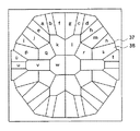
そこで、さらに効率を上げる為には、図11に示すように、異なる形状の開口を有する複数の第2レンズを有するレンズアレイとすればよい。ここで、図11中に示すa〜wは、図5に示した第1レンズアレイ30の各レンズとの対応関係を示している。
【0075】
第2レンズアレイ37は、光軸からの距離に応じて各第2レンズ38の開口と大きさを最適に組み合わせ、光軸近傍に位置するレンズほど、大きな実像に合わせた大きな開口を、光軸から離れて位置するレンズほど、小さな実像に合わせて小さな開口を与えており、これらを最適に組み合わせて、光損失を大きくすることなく、第2レンズアレイ37全体の開口を小さくできる。このように構成した第2レンズアレイを図5に示した第1レンズアレイと組み合わせる場合、第1レンズアレイ30を構成する第1レンズ31の各々は、適当にレンズ光軸をその開口に対して軸ずらし(偏心)させ、第1レンズを出射した光が、対応する第2レンズ38の開口上に到達するように構成するとよい。そしてこのようにすれば、照明スポットへの光の照射角をより小さくできる利点がある。
【0076】
以上説明したように、図4に示した画像表示装置Bにおいては、実現したい光利用効率に応じて、多少の光損失を許容して第1レンズアレイと第2レンズアレイの開口形状を同じに揃えても良いし、図11に示すような第2レンズアレイの開口形状として、その効率と第2レンズアレイの開口サイズを最適化することも可能である。
【0077】
尚、上述の画像表示装置Bにおいて、収束レンズ34を使わない構成とすることも考えられる。収束レンズを使わない場合、第2レンズを適当に偏心させて、これらを通過する部分光束を適宜偏向させ、照明スポット上に各部分光束を重畳すればよい。
【0078】
以上、光学インテグレータ素子としてレンズアレイを用いた場合を説明したが、これ以外に、例えばガラスロッドを光学インテグレータ素子として用いることも考えられる。以下、ガラスロッドを用いた場合について、図面を参照しつつ簡単に説明する。
【0079】
図12は図4に示した画像表示装置Bにおいて、レンズアレイの代わりにガラスロッドを用いた構成とした画像表示装置B’の一部の構成を示した概略図である。画像表示装置Bと同一の構成部分についてはここでは省略している。この画像表示装置B’では、発光体10の放射する光を楕円鏡41により集光し、これを矩形のガラスロッド42に入射させる。ガラスロッド42に入射した光はその側面で全反射を繰り返すことにより、上述した、2枚のレンズアレイを組み合わせた光学インテグレータ素子と同様の作用と効果を得ることができる。この場合、ガラスロッド42の出射端面43は、照明スポット17の形状を決定することより、出射端面の形状は液晶パネル22の表示領域と同じアスペクト比の矩形形状とすればよい。補助レンズ44は、光束を平均化して照明されるガラスロッド出射端部の照明スポットを回転型色フィルタ16上に導くが、これを備えない場合は、ガラスロッド自身が導くように構成すればよい。
【0080】
このようにして光学インテグレータ素子である第1レンズアレイ30と第2レンズアレイ32とを用いることで、もしくはガラスロッド42を用いることで、色純度を高くでき、必要な波長帯域の光をカットすることもない。更に照明スポット17の明るさ均一性が高くなるので、これと共役の関係となる液晶パネル22を照明する光の明るさの均一性が改善され、すなわち、各画角点での光の照射角が、平均化される。従って、回転型色フィルタに入射する光の最大照射角を小さくできるので、より好ましい画像表示装置を実現できる。
【0081】
(実施の形態3)
次に、本発明の請求項4に対応する画像表示装置Cを第3の実施の形態として説明する。
この画像表示装置Cでは、放物面鏡から照明スポットに至る光路に、3つのレンズ群が備えられている。つまり、第1レンズ群により光束を収斂させ発光体の実像を形成する。次に、形成された実像の近傍に第2レンズ群を備えて照明スポットを形成する。この場合、第2レンズ群の主平面が射出瞳に相当する。そして第3レンズ群を照明スポットの近傍に配置して、テレセントリック照明としている。
【0082】
そして、上述した構成は、第1レンズ群を第1レンズアレイ30の第1レンズ31、第2レンズ群を第2レンズアレイ32の第2レンズ33と収束レンズ34、第3レンズ群を補助レンズ35と見なせば、図4に示した構成の画像表示装置そのものとなる。この場合、第2レンズ群をアナモフィックレンズで構成すれば、適当なアスペクト比の矩形の照明スポットを構成できる。そして矩形照明スポットの短辺方向と、回転型色フィルタの配置方向を適切にすれば、第1の実施の形態において説明したのと同様の作用と効果を得る。
【0083】
そこで、以下画像表示装置Cについて図4を参照しつつさらに説明する。
この画像表示装置Cでは、照明スポット17を形成する第1照明系において照明スポット17に対する射出瞳上に発光体10の実像を形成し、また照明スポット17をいわゆるケーラー照明により形成するように構成されている。
【0084】
さらに具体的に説明すると、第1レンズアレイ30は第2レンズアレイ32の開口近傍に複数の発光体10の実像を形成し、これら発光体10の実像を近似する正円領域が照明スポット17を形成する第1照明系の射出瞳となる。従って、このように構成される発光体10と照明スポット17はいわゆる像と瞳の関係となり、その為お互いの共役関係が最も少ない。これに加えて、第2レンズアレイ32を構成する第2レンズ33の各々は有限の開口を有しており、これらの開口は、対応する複数の部分光束の各々について開口絞りとして作用している。尚、対応する第2レンズの開口をはみ出して隣のレンズに入射した光は、照明スポット17の領域には到達しないので、有効に利用されることはない。
【0085】
このように、画像表示装置Cでは照明スポット17に対する射出瞳上に発光体10の実像を形成し、さらに射出瞳に適当な開口絞りを設けているので、発光体10の大きさが変化しても照明スポット17の大きさが変化することがない。従って、量産時におけるランプのばらつきや、ランプ経時変化に依って発光体10の大きさが変化した場合であっても、常に同じ大きさの照明スポット17を得ることができる。また射出瞳に適当な開口絞りを有するので、製造時におけるランプの大きさのばらつきや寿命要因に依って発光体自体の大きさが変化しても、照明スポットのサイズを一定にし、また不要な迷光の発生を抑制できる。従って、予め最適化した時間開口率を用いて、画像表示装置を構成できる。
【0086】
さらに照明スポット17のサイズを常に必要十分な大きさとして一定にできる上に、矩形の照明スポットを形成しこの短辺方向と回転型色フィルタの回転円周方向を一致させているので、画像表示装置Cの時間開口率を高い値で常に一定にできる。また、2枚のレンズアレイからなる光学インテグレータ素子を用いて照明スポットを形成するので、各画角での照明光の照射角を平均化して一定として、色フィルタへの最大入射角を小さくでき、その結果、色分離効率の良い、明るく、色純度の高い、色順次表示方式の表示を実現できる。この2枚のレンズアレイは、例えば図5に示す構成を有する第1レンズアレイと、図11に示す構成を有する第2レンズアレイとの組み合わせとすればなお良い。この図11に示す第2レンズアレイを用いると、第2の実施の形態において説明したように、第2レンズアレイ上に形成される複数の発光体の実像の大きさに合わせて、光損失を増加させることなく、その開口の総和を小さくできるので、より照射角の小さい光で、照明スポットを形成できる。
【0087】
以上述べた画像表示装置A、B、Cは、空間光変調素子として色順次表示方式の透過型液晶パネルを用いる場合を示したが、必ずしもこれに限定されず、例えば反射型の液晶パネルや、反射型のデジタルマイクロミラー素子(DMD)を用いる構成であっても構わない。
【0088】
(実施の形態4)
次に、第1の実施の形態において説明した画像表示装置Aを用いてなる本発明の請求項5に対応する投写型画像表示装置を第4の実施の形態として説明する。
【0089】
図13は第1の実施の形態で説明した画像表示措置Aを用いた本発明の実施の形態4による投写型画像表示装置Dの概略構造図である。
この投写型画像表示装置Dにおいて、画像表示装置Aと同一の部分、即ち図1と同一の部分については同一の符号を附し、その説明を省略する。
【0090】
投写型画像表示装置Dは、画像表示装置Aに投写レンズ48を追加したものである。投写型画像表示装置Dにおいて、透過型液晶パネル22で変調された光は投写レンズ48の入射瞳49に入射し、色順次表示方式で表示される画像は、スクリーン(ここでは図示せず)上に拡大投写されるようになっている。
よって、第1の実施の形態の画像表示装置Aにおけると同様に、時間開口率を高く改善できるので、明るい投写型画像表示装置を得ることが出来る。
【0091】
(実施の形態5)
次に、第2の実施の形態で説明した画像表示装置Bを用いてなる本発明の請求項5に対応する投写型画像表示装置Eを、第5の実施の形態として図14を参照しつつ説明する。
【0092】
図14は第2の実施の形態で説明した画像表示措置Bを用いた本発明の実施の形態5による投写型画像表示装置Eの概略構造図である。
この投写型画像表示装置Eにおいて、画像表示装置Bと同一の部分、即ち図4と同一の部分については同一の符号を附し、その説明を省略する。
【0093】
投写型画像表示装置Eは、画像表示装置Bに投写レンズ45と反射型の空間光変調素子47とを追加したものである。投写型画像表示装置Eにおいて、透過型液晶パネル22で変調された光は反射型の空間光変調素子47を照明し、その変調画像を、投写レンズ45によりスクリーン(図示せず)上に拡大投写されるようになっている。ここで、反射型の空間光変調素子として、例えば、微小なミラーを二次元状に配列したデジタルマイクロミラー素子(DMD素子)を用いると良い。すでに述べたように、DMD素子は微小ミラーのチルト角を制御して光の進行方向をOn/Offするもので、高速応答が可能であると共に、偏光を利用しないので、高い光利用効率を実現できる。
【0094】
また、2枚のレンズアレイ30、32からなる光学インテグレータ素子を使って、矩形の照明スポット17を形成しており、明るさの均一な照明スポットを形成することで、照射角を平均化でき、即ち色フィルタへの最大入射角を小さくできるので、色分離特性の良い、明るく、色純度の高い色順次表示を得られる。そして空間光変調素子47の表示領域と照明スポット17を共役の関係とし、明るさの均一性の高い照明スポット17を形成しているので、空間光変調素子47を照明する光について、明るさの均一性を高くできる。その結果、スクリーンに投影される画像の明るさむらを少なくし、均一性の優れた投写画像を提供できる投写型画像表示装置を得られる。
【0095】
(実施の形態6)
次に、第3の実施の形態で説明した画像表示装置Cを用いてなる本発明の請求項8、請求項9及び請求項10に対応する投写型画像表示装置Fを第6の実施の形態として説明する。この投写型画像表示装置Fの概略構造は図14に示したものと同一である。
【0096】
この投写型画像表示装置Fでは、画像表示装置Cについて説明した通り、照明スポットを形成する射出瞳上に発光体の実像を形成するので、発光体の大きさが変化しても、照明スポットの大きさは変化しない。常に、一定で高い時間開口率を実現できるので、明るく、混色の発生しない投写型画像表示装置Fを実現できる。
【0097】
【発明の効果】
以上述べたように、本発明の請求項1に記載の画像表示装置、及び請求項5に記載の投写型画像表示装置では、矩形の照明スポットを形成するので、色の遷移期間における空間光変調素子の休止時間を短くし、また時間開口率を高く改善できる。また、矩形の照明スポットの短辺方向と回転型色フィルタの円周方向とを一致させるので、より効率の高い、明るい画像表示を可能とする装置を実現する。また、照明スポットを形成する射出瞳上に、発光体の実像を形成するようにしたので、発光体の実像の大きさに依らず、照明スポットの大きさを一定にできるので、常に高い時間開口率を実現すると共に、混色の発生を防止できる。
【0098】
本発明の請求項2に記載の画像表示装置、及び請求項5に記載の投写型画像表示装置では、照明スポットを光学インテグレータ素子を用いて形成するので、明るさの均一性の高い照明スポットを形成でき、照射角を平均化できる。従って、最大照射角を抑制でき、色純度と効率の高い色順次照明を実現できる。また、矩形の照明スポットの短辺方向と回転型色フィルタの円周方向とを一致させるので、より効率の高い、明るい画像表示を可能とする装置を実現する。
【0100】
本発明の請求項4に記載の画像表示装置、及び請求項5に記載の投写型画像表示装置では、第2照明系を入力部収束レンズと、出力部収束レンズと、中央部収束レンズと、で構成したので、照明スポットと空間光変調素子の表示領域とを共役の関係とすることが出来る。
【0101】
本発明の請求項3に記載の画像表示装置、及び請求項5に記載の投写型画像表示装置では、第1照明系を、第1レンズアレイと、第2レンズアレイと、で構成したので、照明スポットの大きさを一定にするのみならず、明るさの均一性も非常に高いものとすることが出来る。
【図面の簡単な説明】
【図1】本発明の画像表示装置の構成の一例を示す略構成図である。
【図2】回転型色フィルタ上に形成される照明スポットの一例を示す略構成図である。
【図3】本発明の画像表示装置が用いる空間光変調素子の時間開口率を説明する略線図である。
【図4】本発明の画像表示装置の他の実施の形態を示す略構成図である。
【図5】第1レンズアレイの構成の一例を示す略構成図である。
【図6】第2レンズアレイの構成の一例を示す略構成図である。
【図7】従来の楕円面鏡における設計パラメータの一例を示す略線図である。
【図8】従来の楕円面鏡における照明スポットの明るさ分布の一例を示す略線図である。
【図9】本発明の画像表示装置における設計パラメータの一例を示す略線図である。
【図10】本発明の画像表示装置における照明スポットの明るさ分布の一例を示す略線図である。
【図11】第2レンズアレイの更に好ましい構成の一例を示す略構成図である。
【図12】本発明の画像表示装置の更に他の実施の形態を示す略構成図である。
【図13】本発明の投写型画像表示装置の構成の一例を示す略構成図である。
【図14】本発明の投写型画像表示装置の他の実施の形態を示す略構成図である。
【図15】従来の画像表示装置の構成の一例を示す略構成図である。
【図16】従来の回転型色フィルタ上に形成される照明スポットの一例を示す略構成図である。
【図17】従来の楕円面鏡の作用を示す略線図である。
【符号の説明】
10 発光体
11 放物面鏡
12 光軸
13、14 アナモフィックレンズ
15、35、44 補助レンズ
16 回転型色フィルタ
17 照明スポット
18 入力部収束レンズ
19 中央部収束レンズ
20 出力部収束レンズ
21 リレーレンズ系
22 液晶パネル
23 モータ
28 ハブ
29R 赤透過フィルタ
29G 緑透過フィルタ
29B 青透過フィルタ
30 第1レンズアレイ
31 第1レンズ
32、37 第2レンズアレイ
33、38 第2レンズ
34 収束レンズ
41 楕円面鏡
42 ガラスロッド
45、48 投写レンズ
46、49 入射瞳
47 反射型空間光変調素子[0001]
BACKGROUND OF THE INVENTION
The present invention is a combination of an illumination optical system that supplies high-speed illumination light of the three primary colors consisting of red, blue, and green, and a spatial light modulator that sequentially displays the primary images of the three primary colors in synchronization with the illumination optical system. The present invention relates to an image display device and a projection type image display device that guides light emitted from the image display device to a projection lens and enlarges and projects a display image of a spatial light modulation element.
[0002]
[Prior art]
Spatial light modulation elements (SLMs) used in image display apparatuses for AV equipment, presentations or workstations, and large-screen projectors (projection-type image display apparatuses) include liquid crystal panels and reflection display elements that are light-receiving display elements. A DMD element (digital micromirror element) is often used.
[0003]
By the way, a liquid crystal panel used for an image display device itself displays a black-and-white image, but in order to construct a color image corresponding to a video signal supplied from the outside, R (red), G (green) ) And B (blue) color original images are displayed in a time-sequentially switched manner at a high speed. For this purpose, a liquid crystal material having a high response speed, such as a ferroelectric liquid crystal, is used. This ferroelectric liquid crystal is generally known as a black and white binary display application. However, by controlling the on period of white display, gradation display using so-called pulse width (time axis) modulation can be performed. It is possible to form primary images of the three primary colors G and B, and in turn, to realize a full color display. In addition, DMD elements used in image display devices, etc. have a two-dimensional arrangement of minute mirror structures, controls the direction in which incident light is reflected, and controls the light spatially to form an optical image. Is configured to do.
[0004]
As a method of constructing a color image in an image display device or a projection type image display device using these liquid crystal panels and DMD elements, three display elements are provided corresponding to the three primary colors of red, blue and green. A method of using a RGB color trio pixel by forming a mosaic color filter on a single display element, or using a single spatial light modulation element for monochrome display as described above, R (red), There is a method generally called a color sequential display method, which is a method of displaying each color original image of G (green) and B (blue) in time series and switching the color of illumination light in synchronization with each color original image.
[0005]
Hereinafter, an image display apparatus using a spatial light modulation element based on this color sequential display method will be described.
FIG. 15 is a schematic diagram of a conventional image display apparatus that employs a spatial light modulation element based on a color sequential display system. A lamp (not shown here) forms a
[0006]
As described above, in an image display device that uses a light source that emits white light, the rotary color filter as described above is used in order to switch white light to high-speed RGB color sequential illumination light. This rotary color filter is an appropriate arrangement of red, green, and blue transmission color filter segments on a circle that is driven by a motor and rotates at high speed, and illuminates these rotating color filters. As a result of the passage of light, color sequential illumination light that switches from R → G → B at high speed is formed.
[0007]
This rotary color filter will be further described with reference to the drawings. FIG. 16 shows an example of the configuration of the
[0008]
By the way, in the
[0009]
As described above, the ratio of the effective image display period excluding the color switching period in the spatial light modulation element to the total period period is called the time aperture ratio of the spatial light modulation element, and the light utilization efficiency of the spatial light modulation element. It is one of the indications showing. Usually, this time aperture ratio is about 80 to 90%. As the time aperture ratio is improved, an image display device capable of obtaining a bright image can be obtained.
[0010]
The time aperture ratio of the spatial light modulator will be further described in the case where the rotary color filter and the liquid crystal panel are combined.
Since the
[0011]
In the
[0012]
Here, in order to make the image of the image display device brighter, it is conceivable to increase the power of the lamp used for the light source. However, increasing the power means an increase in power consumption, and thus in the image display device. This method is not preferred because the calorific value increases. Rather, it is more effective to improve the time aperture ratio.
[0013]
By the way, the temporal aperture ratio of the spatial light modulator depends on the size of the
[0014]
Of these, the method of increasing the size of the rotary color filter can increase the temporal aperture ratio of the spatial light modulator, but the size of the rotary color filter is increased, which makes it difficult to reduce the size of the entire apparatus. Furthermore, this method is not preferable because the color filter becomes expensive and the driving torque of the necessary motor needs to be increased, that is, new problems such as an increase in the size and cost of the motor occur.
[0015]
Therefore, it can be said that reducing the illumination spot is a preferable method for increasing the temporal aperture ratio of the spatial light modulator. The size of the illumination spot is determined by the size of the light emitter used as the light source of the image display device and the irradiation angle of the condensing optical system that forms the illumination spot.
[0016]
First, considering the size of the light emitter, it is obvious that the smaller the light emitter, the smaller the illumination spot.
[0017]
Next, when the irradiation angle of the condensing optical system is examined, if the irradiation angle is increased, the size of the formed image, that is, the size of the illumination spot can be reduced according to the so-called Lagrange-Helmholtz invariant. In this case, the concentration angle of light incident on the color filter is increased, and the color filter acts on a light beam group having a wider angle change range. However, when the above-described dichroic filter used in the rotary color filter of the conventional image display device is applied to the light group having a large irradiation angle, the desired cutoff wavelength is applied to the light group having a large incident angle. Cannot be obtained, and a light beam having a low color purity that is not necessary is allowed to pass through, or conversely, a light beam having a high color purity that is originally required is blocked. That is, for the color light after passing through the filter, it is not possible to obtain the primary color light of the desired color purity, or in order to obtain the desired color purity, it is necessary to shift the cutoff wavelength of the filter to the high color purity side. In order to increase the efficiency of the entire image display device, the light use efficiency of the filter is lowered, and consequently, the efficiency of the entire image display device is lowered and the displayed image becomes dark. It can be said that it is preferable to reduce the light irradiation angle.
[0018]
As described above, it is effective to improve the time aperture ratio of the spatial light modulation element in order to realize a smaller, brighter and better color reproducibility image display device. In order to improve the rate, it is only necessary to reduce the size of the light emitter, use a rotational color filter that is as small as possible, make the illumination spot as small as possible, and further reduce the light irradiation angle to the illumination spot.
[0019]
[Problems to be solved by the invention]
However, in the case of a conventional method of forming an illumination spot with a combination of an ellipsoidal mirror or a parabolic mirror and a condenser lens, the light emitter is miniaturized and a rotation type color filter as small as possible is used. At the same time, it is difficult to reduce the illumination spot as much as possible and to reduce the light irradiation angle to the illumination spot.
[0020]
First, when the illumination angle of the light to the illumination spot is further examined with reference to FIG. 17, the
[0021]
Considering the size of the illuminant, metal halide lamps and high-pressure mercury lamps used for the illuminant of conventional image display devices are small in size even when trying to reduce the illuminant itself to reduce the illumination spot. There is a problem that it is difficult to make. In the case of using a lamp that uses arc discharge, it is conceivable to shorten the distance between the electrodes for forming the arc discharge in order to reduce the illumination spot. There are new problems such as extremely shortening, unstable arc discharge, large lamp current and large power supply. Further, there arises a problem that the size of the light emitter changes during the lifetime according to the lighting time. This is because in the case of a lamp using arc discharge, the electrodes are consumed depending on the lighting time, and if the lighting is repeated, the gap between the electrodes will eventually widen. There is also a problem that the spot becomes gradually larger and eventually the illumination spot becomes larger.
[0022]
As described above, the size of the illumination spot formed on the rotary color filter is determined according to the size of the illuminant if the optical system is constant. The gap gradually increases, that is, the discharge arc also gradually increases, that is, the luminous body also gradually increases. As a result, the illumination spot gradually increases as lighting is repeated.
[0023]
In addition, when mass-producing lamps, it is relatively difficult to accurately manage the gap between the electrodes of all lamps, and the gap distance between the electrodes may vary. The problem of becoming will also arise. That is, it is extremely complicated and difficult to measure the above-mentioned variation for each lamp and to set the time aperture ratio of the spatial light modulator for each product corresponding to each lamp. Therefore, it is necessary to determine the time aperture ratio of the spatial light modulator in accordance with the largest possible light emitter size among variations, which is unrealistic.
[0024]
Furthermore, in order not to generate unnecessary color mixing during the set lifetime of the image display device, assume the maximum size of how large the illumination spot generated by the light emitter after the lamp lifetime has passed in advance, It is necessary to determine the time aperture ratio of the spatial light modulator according to the assumed size of the illumination spot. If the temporal aperture ratio of the spatial light modulator is determined in this way, the image display device is used. When an initial lamp is used immediately after starting, that is, the minimum required time aperture ratio of the spatial light modulation element cannot be obtained, the image display device cannot obtain the necessary brightness immediately after the start of use. After all, it is a problem.
[0025]
Therefore, the present invention has been made in view of such problems, and the object thereof is to increase the time aperture ratio of the spatial light modulator without increasing the size of the apparatus and regardless of the size and state of the light emitter. It is to provide an image display device capable of performing color sequential display with high color purity and efficiency by enabling a high setting, and a projection type image display device using the image display device. .
[0026]
[Means for Solving the Problems]
In order to achieve the above object, in the image display device according to
[0027]
In the image display device according to claim 2 of the present invention,The image display device according to
[0028]
In the image display device according to
[0030]
Claims of the invention4In the image display device according to
[0031]
Claims of the invention5In the projection type image display apparatus according to
[0036]
DETAILED DESCRIPTION OF THE INVENTION
Hereinafter, embodiments of the present invention will be described with reference to the drawings. It should be noted that the embodiment shown here is merely an example, and is not necessarily limited to this embodiment.
[0037]
(Embodiment 1)
First,
FIG. 1 is a schematic configuration diagram of an image display apparatus A according to the first embodiment. The image display apparatus A includes a
[0038]
The
[0039]
The two
[0040]
The
[0041]
The
[0042]
The
[0043]
In the image display apparatus A constituted by these members, the light emitted from the
[0044]
Here, looking at the relationship between the
[0045]
When the image display device A is adapted for a wide screen for digital TV, the
[0046]
By the way, if a perfect circle having the same area is compared with a rectangle, if the diameter of the perfect circle is D, the length x of the short side of the rectangle is y as the length of the long side.
x = (π / 4) · (D / y) · D
It is obvious that π / 4 and D / y are both smaller than 1.
[0047]
Therefore, if the length x of the short side is smaller than the diameter D and the area of the illumination spot is the same, forming the rectangular spot causes the illumination spot to be a color filter rather than the circular spot. Since the time for passing through the joint can be shortened, the time aperture ratio of the
[0048]
In the case of having an aspect ratio different from the above-described aspect ratio, for example, in the case of a display element having an aspect ratio of 4: 3, which is the display size of an ordinary CRT TV currently in circulation, the same as described above. Actions and effects can be obtained.
Thus, the image display apparatus A according to the present embodiment is a screen display apparatus that can realize high color purity by increasing the time aperture ratio of the
[0049]
(Embodiment 2)
Next, claims of the present invention2 andAnd claims3An image display device B corresponding to the above will be described as a second embodiment with reference to the drawings.
FIG. 4 is a schematic configuration diagram of the image display device B. The same members as those of the image display device A shown in FIG. 1 are denoted by the same reference numerals, and description thereof is omitted.
[0050]
In this image display apparatus B, the
[0051]
In the image display device B according to the second embodiment, in order to obtain an illumination spot having a substantially uniform brightness distribution in order to obtain a brighter image with excellent color purity, an optical integrator element is provided in the first illumination system. Has been introduced. Hereinafter, the optical integrator element will be described.
[0052]
The dichroic filter used as the
[0053]
Therefore, when an optical integrator (integrator) element having an optical integration function is introduced into the portion of the first illumination system that forms the
[0054]
Furthermore, by introducing an optical integrator element into the first illumination system, the brightness distribution of the
[0055]
In the second embodiment, a lens array is used as the optical integrator element. Hereinafter, the lens array and the image display apparatus B using the lens array will be further described. However, an optical integrator element other than the lens array is used. It doesn't matter.
[0056]
As shown in FIG. 4, the first illumination system in the image display apparatus B includes a
[0057]
As shown in FIG. 5, the
[0058]
Here, operations of the
[0059]
The partial light beams divided by the
[0060]
In this way, the
[0061]
The converging
[0062]
By configuring the first illumination system in this way, it is possible to specify how much the incident angle of the irradiation light to the
[0063]
First, a case where an illumination spot is formed using a conventional ellipsoidal mirror will be considered.
[0064]
When an ellipsoidal mirror shown in FIG. 7 having a first focal length: F1 = 10 mm and a second focal length: F2 = 100 mm is used, the magnification on the paraxial of the illumination spot formed on the second focal point is
F2 ÷ F1 = 100 ÷ 10 = 10 times
It becomes. In addition, the size of the light emitter in the diameter direction is
1mm × 10 = 10mm
Thus, a circular illumination spot having a diameter of about 10 mm is formed. However, 10 mm in this case is a standard spot size in paraxial calculation. The brightness distribution of the illumination spot is as shown in FIG. In addition, the maximum irradiation angle θ at the illumination spot is about 27.1 degrees when the elliptical mirror condenses within the range of the collection angle α = 135 degrees.
[0065]
Thus, in the conventional method using only the ellipsoidal mirror, the brightness unevenness on the illumination spot is large, that is, as shown in FIG. 8, the light intensity suddenly drops outward from the center of the illumination spot. Thus, it can be seen that the light irradiation angle spreads over a larger range. The same applies to the case where a parabolic mirror and a condenser lens are combined.
[0066]
Next, a case where the
As shown in FIG. 9, if a
[0067]
Next, when the size of a 16: 9 aspect ratio rectangular region having the same area as a 10 mm diameter circular circle, which is an illumination spot obtained by a conventional method, is calculated, the size is 11:82 mm in width and vertical: Since the distance is 6.65 mm, the
θ = tan-1(48.5 ÷ 120) = 22 degrees
It becomes. Further, the brightness distribution in the illumination spot in this case is as shown in FIG.
[0068]
Therefore, comparing the above-described conventional case with the case according to the second embodiment, the size (length) of the illumination spot with respect to the circumferential direction of the rotary color filter is 6 in the case of the image display device B. It is 10 mm for an illumination spot constituted by a conventional ellipsoidal mirror, whereas it can be seen that the image display apparatus B can shorten the time aperture ratio. Further, as is clear when comparing FIG. 8 and FIG. 10 with respect to the short side direction of the rectangular illumination spot, in the case of the present embodiment, less light reaches a region other than the predetermined necessary region. Therefore, color mixing can be prevented more. Further, the maximum irradiation angle of light reaching the illumination spot is 22 degrees in the case of the image display apparatus B, whereas it is 27.1 degrees in the conventional configuration, and reaches the illumination spot in the image display apparatus B. It can be seen that the maximum irradiation angle of the light to be emitted can be further reduced.
[0069]
However, as shown in the above specific example, the surface interval between the first lens array and the second lens array must be appropriate in order to prevent color mixing and reduce the maximum irradiation angle. That is, it is obvious that if the distance X2 is large, X1 is also large and the irradiation angle to the illumination spot is small. That is, the maximum irradiation angle of 22 degrees can be obtained with an appropriate combination of X1 and X2.
[0070]
By the way, although the size of the second lens constituting the second lens array shown in FIG. 6 is all the same, the real image of the illuminant is not completely covered, so that light loss occurs. Accordingly, a lens array that reduces the optical loss by using a configuration different from the second lens array shown in FIG. 6 will be described below with reference to the drawings.
[0071]
If the distance X2 in the image display device B shown in FIG. 9 is increased, the real image of the light emitter formed on the second lens becomes larger, and light loss is caused for the light formed by protruding from the opening of the second lens. . Further, if the distance X2 is shortened, the real image of the light emitter on the second lens becomes smaller and the light loss is reduced. However, if the real image of the light emitter is too small with respect to the opening of the second lens, the second Since each of the partial light beams passes through the aperture of the entire lens array in a small and discrete manner, the limited aperture area cannot be used effectively as a result.
[0072]
Here, the size of the real image formed on the second lens will be examined with reference to FIG. For the apex A portion of the parabolic mirror, which is an axial point, the distance at which the luminous body is viewed is 10 mm, and the thickness of the luminous body seen from this direction is 1 mm. And the angle to look at the illuminant is tan-1Since (0.1) = 5.7 degrees, the light (Ls) passing through the lens close to the axis (in FIG. 6, for example, the second lens 33w) has a numerical aperture corresponding to this angle. The light can be used most efficiently. The size of the real image at the distance X2 (= 154 mm) is about 15 mm. Further, regarding the light in the condensing direction of α = 90 degrees, for example, when considering the portion B which is a position corresponding to α = 90 degrees, the distance of the light emitting body seen from this portion is 20 mm, and the light emitting body seen from this direction The length is 2 mm. The size of the real image in the second lens (for example, the second lens 33k in FIG. 6) existing in the vicinity of the path (Lt) is about 15 mm.
[0073]
However, the angle at which the illuminant is seen sharply decreases when going beyond the portion B toward the periphery of the parabolic mirror. For example, when considering part C corresponding to α = about 135 degrees, the distance of the luminous body seen from this part is 45 mm, and the length of the luminous body seen from this direction is 2 mm. And the angle which looks at a light-emitting body will become small to about 1.4 degree | times. A lens (for example, the second lens 33b in FIG. 6) close to the light (Lu) path can use light most efficiently if it has a numerical aperture corresponding to this angle. However, the size of the real image in this portion is only about 4 mm, and in the second lens array shown in FIG. 6, the numerical apertures of all the second lenses are the same, so that light is always used efficiently. I can't say that.
[0074]
Therefore, in order to further increase the efficiency, as shown in FIG. 11, a lens array having a plurality of second lenses having differently shaped openings may be used. Here, a to w shown in FIG. 11 indicate the corresponding relationship with each lens of the
[0075]
The
[0076]
As described above, in the image display apparatus B shown in FIG. 4, the first lens array and the second lens array have the same opening shape by allowing some light loss according to the light utilization efficiency to be realized. The apertures of the second lens array as shown in FIG. 11 can be optimized, and the efficiency and the aperture size of the second lens array can be optimized.
[0077]
In the image display apparatus B described above, a configuration in which the converging
[0078]
The case where the lens array is used as the optical integrator element has been described above. However, for example, a glass rod may be used as the optical integrator element. Hereinafter, the case where a glass rod is used will be briefly described with reference to the drawings.
[0079]
FIG. 12 is a schematic diagram showing a partial configuration of the image display device B ′ in which the glass rod is used instead of the lens array in the image display device B shown in FIG. 4. The same components as those of the image display device B are omitted here. In this image display apparatus B ′, the light emitted from the
[0080]
Thus, by using the
[0081]
(Embodiment 3)
Next, claims of the present invention4An image display apparatus C corresponding to the above will be described as a third embodiment.
In this image display device C, three lens groups are provided in the optical path from the parabolic mirror to the illumination spot. That is, the luminous flux is converged by the first lens group to form a real image of the light emitter. Next, an illumination spot is formed by providing a second lens group in the vicinity of the formed real image. In this case, the main plane of the second lens group corresponds to the exit pupil. The third lens group is arranged in the vicinity of the illumination spot to provide telecentric illumination.
[0082]
In the configuration described above, the first lens group is the
[0083]
Therefore, the image display device C will be further described below with reference to FIG.
This image display device C is configured to form a real image of the
[0084]
More specifically, the
[0085]
As described above, in the image display apparatus C, the real image of the
[0086]
Further, since the size of the
[0087]
The image display apparatuses A, B, and C described above have shown the case of using a transmissive liquid crystal panel of a color sequential display system as a spatial light modulation element, but is not necessarily limited to this, for example, a reflective liquid crystal panel, A configuration using a reflective digital micromirror element (DMD) may also be used.
[0088]
(Embodiment 4)
Next, claims of the present invention using the image display apparatus A described in the first embodiment5A projection type image display apparatus corresponding to the above will be described as a fourth embodiment.
[0089]
FIG. 13 is a schematic structural diagram of a projection-type image display apparatus D according to
In this projection type image display apparatus D, the same parts as those of the image display apparatus A, that is, the same parts as in FIG.
[0090]
The projection type image display apparatus D is obtained by adding a
Therefore, as in the image display apparatus A of the first embodiment, the time aperture ratio can be improved and a bright projection type image display apparatus can be obtained.
[0091]
(Embodiment 5)
Next, claims of the present invention using the image display apparatus B described in the second embodiment5A projection type image display apparatus E corresponding to is described as a fifth embodiment with reference to FIG.
[0092]
FIG. 14 is a schematic structural diagram of a projection-type image display apparatus E according to Embodiment 5 of the present invention that uses the image display measure B described in the second embodiment.
In this projection type image display apparatus E, the same parts as those of the image display apparatus B, that is, the same parts as in FIG.
[0093]
The projection type image display apparatus E is obtained by adding a
[0094]
In addition, a
[0095]
(Embodiment 6)
Next, a projection type image display apparatus F corresponding to
[0096]
In the projection type image display device F, as described for the image display device C, a real image of the light emitter is formed on the exit pupil that forms the illumination spot. The size does not change. Since a constant and high time aperture ratio can always be realized, it is possible to realize a projection type image display apparatus F that is bright and does not generate color mixing.
[0097]
【The invention's effect】
As described above, the image display device according to
[0098]
An image display device according to claim 2 of the present invention, and claim5In the projection type image display apparatus described in 1), since the illumination spot is formed using the optical integrator element, it is possible to form an illumination spot with high uniformity of brightness and to average the irradiation angle. Therefore, the maximum irradiation angle can be suppressed, and color sequential illumination with high color purity and efficiency can be realized. In addition, since the short side direction of the rectangular illumination spot is matched with the circumferential direction of the rotary color filter, a device capable of displaying bright images with higher efficiency is realized.
[0100]
Claims of the invention4And an image display device according to claim 1.5In the projection-type image display device described in (1), the second illumination system is composed of an input unit converging lens, an output unit converging lens, and a central converging lens. It can be a conjugate relationship.
[0101]
An image display device according to
[Brief description of the drawings]
FIG. 1 is a schematic configuration diagram showing an example of a configuration of an image display device of the present invention.
FIG. 2 is a schematic configuration diagram illustrating an example of an illumination spot formed on a rotary color filter.
FIG. 3 is a schematic diagram illustrating a time aperture ratio of a spatial light modulation element used by the image display device of the present invention.
FIG. 4 is a schematic configuration diagram showing another embodiment of the image display device of the present invention.
FIG. 5 is a schematic configuration diagram illustrating an example of a configuration of a first lens array.
FIG. 6 is a schematic configuration diagram illustrating an example of a configuration of a second lens array.
FIG. 7 is a schematic diagram illustrating an example of design parameters in a conventional ellipsoidal mirror.
FIG. 8 is a schematic diagram illustrating an example of a brightness distribution of an illumination spot in a conventional ellipsoidal mirror.
FIG. 9 is a schematic diagram illustrating an example of design parameters in the image display apparatus of the present invention.
FIG. 10 is a schematic diagram illustrating an example of a brightness distribution of an illumination spot in the image display apparatus of the present invention.
FIG. 11 is a schematic configuration diagram showing an example of a more preferable configuration of the second lens array.
FIG. 12 is a schematic configuration diagram showing still another embodiment of the image display device of the present invention.
FIG. 13 is a schematic configuration diagram showing an example of a configuration of a projection type image display apparatus of the present invention.
FIG. 14 is a schematic configuration diagram showing another embodiment of the projection type image display apparatus of the present invention.
FIG. 15 is a schematic configuration diagram illustrating an example of a configuration of a conventional image display apparatus.
FIG. 16 is a schematic configuration diagram showing an example of an illumination spot formed on a conventional rotary color filter.
FIG. 17 is a schematic diagram showing the operation of a conventional ellipsoidal mirror.
[Explanation of symbols]
10 Light emitter
11 Parabolic mirror
12 optical axes
13, 14 Anamorphic lens
15, 35, 44 Auxiliary lens
16 Rotating color filter
17 Lighting spot
18 Input unit convergence lens
19 Central convergent lens
20 Output unit convergence lens
21 Relay lens system
22 LCD panel
23 Motor
28 Hub
29R red transmission filter
29G Green transmission filter
29B Blue transmission filter
30 First lens array
31 First lens
32, 37 Second lens array
33, 38 Second lens
34 Converging lens
41 Ellipsoidal mirror
42 Glass rod
45, 48 Projection lens
46, 49 Entrance pupil
47 Reflective spatial light modulator
Claims (5)
前記光源の放射光を集めて略単一の光束を形成する集光手段と、
前記集光手段によって形成された光束を用いて矩形の照明スポットを形成する第1照明系と、
前記照明スポット近傍に配置されて前記白色光を赤、青、緑の各色光に順次切り替える円形状の回転型色フィルタと、
赤、青、緑の各色原画像を時系列的に切替えて表示することに用いる空間光変調素子と、
前記回転型色フィルタを通過した光を集光して前記空間光変調素子を照明する照明光を形成する第2照明系と、を備えた画像表示装置であって、
前記第1照明系は、前記回転型色フィルタを通過する光線群の主光線を略光軸に平行に進行させる補助レンズを備え、前記空間光変調素子の表示領域のアスペクト比に略等しいアスペクト比を有する前記照明スポットを形成し、
前記第2照明系は、前記回転型色フィルタを通過した光線群を収束させる入力部収束レンズを備え、前記回転型色フィルタによって形成される赤、青、緑の各色光の出力と前記空間光変調素子の表示とを同期させて、前記照明スポットと前記空間光変調素子とを略共役の関係とさせ、
前記照明スポットの短辺方向と、前記回転型色フィルタの円周方向とを略一致させ、
前記補助レンズと前記入力部収束レンズとを前記回転型色フィルタの前後に配置させるとともに、
前記第1照明系は、前記照明スポットを形成する射出瞳の近傍に前記光源の実像を形成すると共に、前記射出瞳の近傍に開口絞りを備えた、
ことを特徴とする、画像表示装置。A light source that emits white light;
Condensing means for collecting the emitted light of the light source to form a substantially single luminous flux;
A first illumination system that forms a rectangular illumination spot using a light beam formed by the light collecting means;
A circular rotary color filter disposed in the vicinity of the illumination spot and sequentially switching the white light to red, blue and green color light;
A spatial light modulation element used to switch and display original images of red, blue, and green in time series;
A second illumination system that collects the light that has passed through the rotary color filter and illuminates the spatial light modulator to illuminate the spatial light modulator, and an image display device comprising:
The first illumination system includes an auxiliary lens that advances a principal ray of a light ray group that passes through the rotary color filter substantially parallel to an optical axis, and has an aspect ratio that is substantially equal to an aspect ratio of a display area of the spatial light modulator. Forming the illumination spot having
The second illumination system includes an input unit converging lens that converges a light beam that has passed through the rotary color filter, and outputs the red, blue, and green color lights and the spatial light formed by the rotary color filter. Synchronizing the display of the modulation element, the illumination spot and the spatial light modulation element are in a substantially conjugate relationship,
The short side direction of the illumination spot and the circumferential direction of the rotary color filter are substantially matched,
While arranging the auxiliary lens and the input unit converging lens before and after the rotary color filter ,
The first illumination system includes a real image of the light source in the vicinity of an exit pupil that forms the illumination spot, and an aperture stop in the vicinity of the exit pupil.
An image display device characterized by that.
前記第1照明系は、前記照明スポットを光学インテグレータ素子で形成する、
ことを特徴とする、画像表示装置。The image display device according to claim 1,
The first illumination system forms the illumination spot with an optical integrator element.
An image display device characterized by that.
前記第1照明系は、前記光学インテグレータ素子が、複数のレンズを二次元状に配列してなる、第1レンズアレイと第2レンズアレイとで構成され、
前記第1レンズアレイは、前記集光手段から出射する光束を複数の部分光束に分割すると共に、前記部分光束を前記第1レンズアレイに対応する前記第2レンズアレイの開口近傍に収斂させ、
前記第2レンズアレイは、対応する前記第1レンズアレイから出射する前記複数の部分光束を回転型色フィルタの近傍に導くと共にこれらを重畳させて照明スポットを形成する、
ことを特徴とする、画像表示装置。The image display device according to claim 2,
The first illumination system includes a first lens array and a second lens array, in which the optical integrator element is formed by two-dimensionally arranging a plurality of lenses.
The first lens array divides a light beam emitted from the condensing unit into a plurality of partial light beams, and converges the partial light beam in the vicinity of an opening of the second lens array corresponding to the first lens array,
The second lens array guides the plurality of partial light beams emitted from the corresponding first lens array to the vicinity of the rotary color filter and superimposes them to form an illumination spot.
An image display device characterized by that.
前記第2照明系は、
前記回転型色フィルタ近傍に配置される入力部収束レンズと、
前記空間光変調素子近傍に配置される出力部収束レンズと、
前記入力部収束レンズと前記出力部収束レンズの間の光路に配置される中央部収束レンズと、を備え、
前記入力部収束レンズは前記入力部収束レンズに入射する光を前記中央部収束レンズの開口中心近傍に収斂させ、
前記中央部収束レンズは前記入力部収束レンズの主平面近傍の物体の実像を前記出力部収束レンズの主平面近傍に形成し、
前記出力部収束レンズは前記中央部収束レンズから出射する光を前記空間光変調素子に有効に導く、
ことを特徴とする、画像表示装置。The image display device according to any one of claims 1 to 3 ,
The second illumination system includes
An input part converging lens disposed in the vicinity of the rotary color filter;
An output part converging lens disposed in the vicinity of the spatial light modulator;
A central convergent lens disposed in an optical path between the input convergent lens and the output convergent lens;
The input part converging lens converges the light incident on the input part converging lens in the vicinity of the opening center of the central part converging lens,
The central convergent lens forms a real image of an object near the principal plane of the input convergent lens near the principal plane of the output convergent lens,
The output convergent lens effectively guides the light emitted from the central convergent lens to the spatial light modulator.
An image display device characterized by that.
前記空間光変調素子上に表示される光学像を投影する投写レンズを備えた、
ことを特徴とする、投写型画像表示装置。A projection-type image display device using the image display device according to any one of claims 1 to 4 ,
A projection lens for projecting an optical image displayed on the spatial light modulator;
A projection-type image display device characterized by the above.
Priority Applications (1)
| Application Number | Priority Date | Filing Date | Title |
|---|---|---|---|
| JP2000319881A JP4094805B2 (en) | 2000-10-19 | 2000-10-19 | Image display device and projection-type image display device |
Applications Claiming Priority (1)
| Application Number | Priority Date | Filing Date | Title |
|---|---|---|---|
| JP2000319881A JP4094805B2 (en) | 2000-10-19 | 2000-10-19 | Image display device and projection-type image display device |
Publications (3)
| Publication Number | Publication Date |
|---|---|
| JP2002131687A JP2002131687A (en) | 2002-05-09 |
| JP2002131687A5 JP2002131687A5 (en) | 2006-02-16 |
| JP4094805B2 true JP4094805B2 (en) | 2008-06-04 |
Family
ID=18798263
Family Applications (1)
| Application Number | Title | Priority Date | Filing Date |
|---|---|---|---|
| JP2000319881A Expired - Fee Related JP4094805B2 (en) | 2000-10-19 | 2000-10-19 | Image display device and projection-type image display device |
Country Status (1)
| Country | Link |
|---|---|
| JP (1) | JP4094805B2 (en) |
Families Citing this family (7)
| Publication number | Priority date | Publication date | Assignee | Title |
|---|---|---|---|---|
| JP4616577B2 (en) * | 2004-04-22 | 2011-01-19 | 株式会社日立製作所 | Video display device |
| JP2006011088A (en) * | 2004-06-25 | 2006-01-12 | Funai Electric Co Ltd | Projector |
| CN101454719B (en) | 2006-05-29 | 2010-06-23 | 松下电器产业株式会社 | Projection type display apparatus |
| JP2008145580A (en) * | 2006-12-07 | 2008-06-26 | Ushio Inc | Optical system for projector |
| JP6078956B2 (en) * | 2012-02-29 | 2017-02-15 | セイコーエプソン株式会社 | Projector and lens array |
| US20150281631A1 (en) * | 2012-11-07 | 2015-10-01 | Hitachi Maxell, Ltd. | Projection-type video display apparatus |
| JP5938335B2 (en) * | 2012-11-20 | 2016-06-22 | 日立マクセル株式会社 | Projection display device |
-
2000
- 2000-10-19 JP JP2000319881A patent/JP4094805B2/en not_active Expired - Fee Related
Also Published As
| Publication number | Publication date |
|---|---|
| JP2002131687A (en) | 2002-05-09 |
Similar Documents
| Publication | Publication Date | Title |
|---|---|---|
| JP4111074B2 (en) | projector | |
| KR100382953B1 (en) | Picture display device | |
| KR100860983B1 (en) | Single panel type color display device | |
| JPWO2005083493A1 (en) | Illumination light source and two-dimensional image display apparatus using the same | |
| JPH07152032A (en) | 2-light-source illuminator | |
| KR20060089502A (en) | Light tunnel and projection apparatus having the same | |
| US20050157275A1 (en) | Compact projection systems using multiple light sources | |
| JP2004004793A (en) | Optical system and display apparatus using this | |
| US20060146414A1 (en) | Illumination optical system, image display apparatus using same and image display method | |
| JP4790228B2 (en) | Illumination method and display device | |
| JP4094805B2 (en) | Image display device and projection-type image display device | |
| JP2002122808A (en) | Projection type display device | |
| JP3893845B2 (en) | Projection-type image display device | |
| JP4736350B2 (en) | Projector and display device | |
| US6811263B2 (en) | Colored light separating device and single-panel color image display apparatus using the same | |
| JP2000347324A (en) | Image display device | |
| JP2003295316A (en) | Display device and projection type display device | |
| JP4655514B2 (en) | projector | |
| JP2006098936A (en) | Projection type display device | |
| JPH11101949A (en) | Illumination means, and illuminator and projection type display device using the same means | |
| JP4003606B2 (en) | Illumination optical device and projector using the same | |
| JPH09211724A (en) | Projection type liquid crystal display device | |
| JP2004170549A (en) | Single plate type image display and single plate projection type image display | |
| JP2001066693A (en) | High luminance projector using single plate reflection type element | |
| JP2006267984A (en) | Projector |
Legal Events
| Date | Code | Title | Description |
|---|---|---|---|
| A521 | Written amendment |
Free format text: JAPANESE INTERMEDIATE CODE: A523 Effective date: 20051227 |
|
| A621 | Written request for application examination |
Free format text: JAPANESE INTERMEDIATE CODE: A621 Effective date: 20051227 |
|
| A131 | Notification of reasons for refusal |
Free format text: JAPANESE INTERMEDIATE CODE: A131 Effective date: 20071030 |
|
| A521 | Written amendment |
Free format text: JAPANESE INTERMEDIATE CODE: A523 Effective date: 20071227 |
|
| TRDD | Decision of grant or rejection written | ||
| A01 | Written decision to grant a patent or to grant a registration (utility model) |
Free format text: JAPANESE INTERMEDIATE CODE: A01 Effective date: 20080212 |
|
| A61 | First payment of annual fees (during grant procedure) |
Free format text: JAPANESE INTERMEDIATE CODE: A61 Effective date: 20080306 |
|
| FPAY | Renewal fee payment (event date is renewal date of database) |
Free format text: PAYMENT UNTIL: 20110314 Year of fee payment: 3 |
|
| R150 | Certificate of patent or registration of utility model |
Free format text: JAPANESE INTERMEDIATE CODE: R150 |
|
| LAPS | Cancellation because of no payment of annual fees |