JP4094440B2 - Trigger type liquid ejector - Google Patents
Trigger type liquid ejector Download PDFInfo
- Publication number
- JP4094440B2 JP4094440B2 JP2003017732A JP2003017732A JP4094440B2 JP 4094440 B2 JP4094440 B2 JP 4094440B2 JP 2003017732 A JP2003017732 A JP 2003017732A JP 2003017732 A JP2003017732 A JP 2003017732A JP 4094440 B2 JP4094440 B2 JP 4094440B2
- Authority
- JP
- Japan
- Prior art keywords
- liquid
- cylinder
- container
- piston
- path
- Prior art date
- Legal status (The legal status is an assumption and is not a legal conclusion. Google has not performed a legal analysis and makes no representation as to the accuracy of the status listed.)
- Expired - Fee Related
Links
Images


Classifications
-
- B—PERFORMING OPERATIONS; TRANSPORTING
- B05—SPRAYING OR ATOMISING IN GENERAL; APPLYING FLUENT MATERIALS TO SURFACES, IN GENERAL
- B05B—SPRAYING APPARATUS; ATOMISING APPARATUS; NOZZLES
- B05B11/00—Single-unit hand-held apparatus in which flow of contents is produced by the muscular force of the operator at the moment of use
- B05B11/01—Single-unit hand-held apparatus in which flow of contents is produced by the muscular force of the operator at the moment of use characterised by the means producing the flow
- B05B11/10—Pump arrangements for transferring the contents from the container to a pump chamber by a sucking effect and forcing the contents out through the dispensing nozzle
- B05B11/1001—Piston pumps
- B05B11/1009—Piston pumps actuated by a lever
- B05B11/1011—Piston pumps actuated by a lever without substantial movement of the nozzle in the direction of the pressure stroke
-
- B—PERFORMING OPERATIONS; TRANSPORTING
- B05—SPRAYING OR ATOMISING IN GENERAL; APPLYING FLUENT MATERIALS TO SURFACES, IN GENERAL
- B05B—SPRAYING APPARATUS; ATOMISING APPARATUS; NOZZLES
- B05B11/00—Single-unit hand-held apparatus in which flow of contents is produced by the muscular force of the operator at the moment of use
- B05B11/01—Single-unit hand-held apparatus in which flow of contents is produced by the muscular force of the operator at the moment of use characterised by the means producing the flow
- B05B11/10—Pump arrangements for transferring the contents from the container to a pump chamber by a sucking effect and forcing the contents out through the dispensing nozzle
- B05B11/1081—Arrangements for pumping several liquids or other fluent materials from several containers, e.g. for mixing them at the moment of pumping
- B05B11/1084—Arrangements for pumping several liquids or other fluent materials from several containers, e.g. for mixing them at the moment of pumping each liquid or other fluent material being pumped by a separate pump
Description
【0001】
【発明の属する技術分野】
本発明は、レバーを牽曳して容器内の液体を吸引、加圧して噴射ノズルより噴出させる液体噴出器に関し、複数の容器に充填された種類の異なる2種類以上の液体を正確な割合にして効率よく噴出させようとするものである。
【0002】
【従来の技術】
トリガー式の液体噴出器は、黴び取り剤や洗剤等を充填する容器に多用されており、その構成は、一般に先端部分に噴射ノズルを取り付けたボディと、このボディに枢支軸を介して揺動可能に支持されたレバーと、ボディ内でポンプ機構を形成するピストン及びシリンダからなっている。
【0003】
かかる噴出器は、レバーを繰返し牽曳しシリンダ内のピストンを作動させることによって液体を吸引、加圧、噴出さるものであって、これによれば環境汚染につながるような加圧媒体を使用せずとも噴射ノズルから液体を連続的に噴出させることができるようになっている。
【0004】
ところで、近年では、トリガー式噴出器にて噴出させるべき液体も多様化されており、例えば、原液とうすめ液をそれぞれ別々の容器に充填しておき、噴出時に各液体を混合して噴射ノズルから噴出させる噴出器も提案されている(例えば特許文献1参照)。
【0005】
【特許文献1】
特開平8−196957号公報
【0006】
上記のような混合タイプの噴出器は、うすめ液が水であるような場合に、原液を充填した容器を取り替えるのみでもう一方の容器を再利用できることから資源の有効利用を図る観点からはとくに有用であるとされていた。
【0007】
しかしながら、従来の混合タイプの噴出器は、吸引管によって各容器内から吸引された液体はその出側ですぐさま混合された状態になってしまうことから、液体の混合割合を正確に調整するのが困難であり、しかも、液体の噴出を停止しているにもかかわらず、シリンダの吸引経路(吸引管出側からシリンダの入側に至るまでの経路)内には、混合状態にある液体が常に溜まった状態にあり、これが、噴出すべき液体の品質に悪影響を与えることが懸念されていた。
【0008】
【発明が解決しようとする課題】
本発明の課題は、液体の混合割合を比較的簡単、かつ正確に調整でき、噴出時にのみ液体を混合させて噴出することができる新規なトリガー式液体噴出器を提案するところにある。
【0009】
【課題を解決するための手段】
本発明は、レバーの牽曳にてピストンを往復移動させて容器内の液体を吸引、加圧して噴射ノズルより噴出させるトリガー式液体噴出器であって、
少なくとも2つの受圧体を有するピストンと、このピストンの各受圧体をそれぞれ摺動可能に嵌入させて内容物の吸入、加圧空間を形成する少なくとも2つのシリンダとを備え、
前記シリンダは、容器内の液体を該シリンダに送給する送給経路と、シリンダ内で加圧した液体を排出する排出経路を有し、
前記シリンダの排出経路とこの排出経路につながる噴射ノズルの相互間に、各シリンダにて加圧した液体を混合して噴射ノズルに向けて圧送する混合経路を設け、
該シリンダの送給経路及び排出経路の相互間に、その経路の断面積を調整するステムを配置したことを特徴とするトリガー式液体噴出器である。
【0010】
上記の構成になる噴出器においてピストンを、レバーに係合する単一の基部とこの基部の同一軸線上で直列に配置された少なくとも2つの受圧体からなるものにて構成するか、あるいは、レバーに係合する単一の基部とこの基部に並列に配置された少なくとも2つの受圧体からなるものにて構成することができる。
【0011】
【発明の実施の形態】
以下、図面を用いて本発明をより具体的に説明する。
【0012】
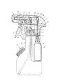
図1は本発明に従うトリガー式液体噴出器を2種類の液体をそれぞれ充填した剛性の高い容器Aと減容可能な薄肉容器Bに装着した実施の形態を示したものであり、図における1は各容器の口部に固定保持されるボディ、2はボディ1に枢支軸P及びコイルスプリングcを介して揺動可能に弾性保持されるレバー、3は噴射ノズルである。
【0013】
また、4はピストンであり、このピストン4はレバー2に係合する単一の基部4aとこの基部4aの同一軸線上で直列に配置された径の異なる大小2つの受圧体4b1、4b2からなる。5a、5bはボディ1内に設けられピストン4の各受圧体4b1、4b2を摺動可能に嵌入させて液体の吸入、加圧空間を形成する径の異なるシリンダ、6はボール状の逆止弁を備え吸引管7によって吸引した容器A内の液体をシリンダ5aに送給する送給経路、8は同じくボール状の逆止弁を備え吸引管9によって吸引した容器B内の液体をシリンダ5bに送給する送給経路である。送給経路6、8に配置される逆止弁はボール状のものを例として示したが、本発明はこれに限定されるものではく、後述する排出経路(10、11)に配置されるような逆止弁やその他公知の逆止弁に置き換えることが可能であり、適宜に選択される。
【0014】
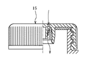
また、10は合成樹脂製のコイルスプリング等にて一体的に弾性支持された逆止弁あるいは合成樹脂やステンレスの如き金属部材で形成されたコイルスプリング等にて別体に弾性支持された逆止弁を有しシリンダ5a内で加圧された液体を排出する排出経路、11は同じくコイルスプリング等によって弾性支持された逆止弁を有しシリンダ5b内で加圧された液体を排出する排出経路、12は排出経路10、11と噴射ノズル3の相互間に配置され排出経路10、11を通って排出された液体を混合する混合経路を形成する管体、13は送給経路8及び排出経路11の相互にわたって配置されその経路の断面積を調整するステム、14は管体12及びボディ1を覆い隠すカバー、そして15は容器Aの減圧に伴う変形を防止する吸気弁である。吸気弁15は容器Aに螺合するキャップ形式のものが適用可能であり、この吸気弁15を取り外すことで噴出器を容器から取り外すことなしに液体の補充ができるようになっている。図2に吸気弁15の要部を断面で示す。
【0015】
レバー2を牽曳してピストン4の各受圧体4b1、4b2をシリンダ5a、5bの奥底に近づけた状態で牽曳にかかわる力を解除すると、レバー2はコイルスプリングcの弾性力でもって初期位置に復帰し、この時、シリンダ5a、5b内は減圧されることになり容器A内の液体は吸引管7、送給経路6を通ってシリンダ5aに吸い込まれると同時に容器B内の液体も吸引管9、送給経路8を通ってシリンダ5Bに吸い込まれることになる。
【0016】
この状態で再度、レバー2を牽曳すると、シリンダ5a、5b内の液体はピストン4の受圧体4b1、4b2によって加圧されることになり、所定の圧力に達した時点で各液体は各排出経路10、11を経て管体12の経路に排出されるとともにここで混合され噴射ノズル3を通して外界へと噴出されることになる。
【0017】
上記のような構成になる噴出器は、排出経路10、11の出側、すなわち、管体12でもって初めて液体が混合されるものであり、混合状態にある液体が排出経路10、11、シリンダ5a、5bあるいは送給経路6、8内に存在することはなく液体の品質の安定化が図られる。
【0018】
また、送給経路8及び排出経路10にステム13の如き部材を配置して経路の径を調整するか、ピストン4の受圧体4b1、4b2の径とシリンダ5a、5bの径を適宜調整するか、吸引管7、9の径を適宜調整するか、あるいは経路の長さを調整することで液体の混合割合は正確、かつ簡便に変更し得る。このような調整を施すことで、液体の噴出開始時に単一の経路からのみ液体が噴出してしまう事象を確実に防止することができる。
【0019】
上掲図1では、容器Aに吸気弁15を設けた構造とし、容器Bは容器内の減圧に従い図3に示すように減容可能とする薄肉のもの(また、内層が剥離、減容するデラミ容器やパウチ容器を適用することもできる)を例として示したが、容器Bについては図4の如く容器Aと同等の剛性を有するものとしてその胴部に吸気弁15を配置してもよく、この場合、容器A、容器Bともに再利用することができ、資源の有効活用を図るのに有用となる。
【0020】
また、ボディ1のベース部1aに図5に示すように容器Aの内外に通じる貫通孔hを設け、レバー2を牽曳したとき容器内に空気を流入させることができる場合には吸気弁15の配置は省略することが可能であり、貫通孔hを設けた構造とするか、吸気弁15を設けた構造とするかは必要に応じて適宜に選択すればよい。
【0021】
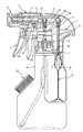
図6は、容器A、B、Cのそれぞれに充填した液体を混合して噴出させる構造になる本発明に従う他の実施の形態を示した図である。
【0022】
図6に示したところの噴出器は、ピストン4に受圧体4b3をさらに設けるとともに、この受圧体4b3に対応するシリンダ5c、送給経路16、排出経路17を配置したものであり、この場合も、各容器A〜Cに充填された液体は管体12において混合されたのち噴射ノズル3から噴出される。
【0023】
本発明の実施の形態では、受圧体4b1、4b2、4b3をピストン4の軸心に沿って直列に配置し、これを各シリンダ5a〜5cにおいて同時に摺動させるようにしたが、ピストン4の受圧体はその基部4aに対して並列に配置した構造としてもよく、図示のものに限定されることはない。
【0024】
【発明の効果】
本発明によれば、液体の混合割合を比較的簡単、かつ正確に調整できるだけでなく、混合状態の液体が噴出器内に留まることがないので噴出すべき液体の品質に悪影響を与えることがない。
【図面の簡単な説明】
【図1】 本発明に従う噴出器の実施の形態を示した図である。
【図2】 吸気弁の断面を右側半分について示した図である。
【図3】 容器Bの減容状態を示した図である。
【図4】 本発明に従う噴出器の他の実施の形態を示した図である。
【図5】 本発明に従う噴出器の他の実施の形態を示した図である。
【図6】 3種類の液体を噴出する構造の噴出器の構成例を示した図である。
【符号の説明】
1 ボディ
1a ベース部
2 レバー
3 噴射ノズル
4 ピストン
4a 基部
4b1 受圧体
4b2 受圧体
4b3 受圧体
5a シリンダ
5b シリンダ
5c シリンダ
6 送給経路
7 吸引管
8 送給経路
9 吸引管
10 排出経路
11 排出経路
12 管体
13 ステム
14 カバー
15 吸気弁
16 送給経路
17 排出経路[0001]
BACKGROUND OF THE INVENTION
The present invention relates to a liquid ejector that checks a lever, sucks and pressurizes liquid in a container, and ejects the liquid from an injection nozzle, and makes two or more different kinds of liquid filled in a plurality of containers an accurate ratio. It is intended to be ejected efficiently.
[0002]
[Prior art]
Trigger-type liquid ejectors are often used in containers filled with wiping agents, detergents, etc. The structure is generally composed of a body with an injection nozzle attached to the tip, and this body via a pivot shaft. It consists of a lever supported in a swingable manner, and a piston and a cylinder that form a pump mechanism within the body.
[0003]
Such an ejector sucks, pressurizes, and ejects liquid by repeatedly checking a lever and operating a piston in a cylinder. According to this, a pressurized medium that leads to environmental pollution is used. At least the liquid can be continuously ejected from the ejection nozzle.
[0004]
By the way, in recent years, the liquid to be ejected by the trigger type ejector has also been diversified. For example, the raw liquid and the thin liquid are filled in separate containers, and the liquids are mixed at the time of ejection from the ejection nozzle. An ejector for ejecting has also been proposed (see, for example, Patent Document 1).
[0005]
[Patent Document 1]
Japanese Patent Laid-Open No. 8-196957
From the viewpoint of effective use of resources, the mixing type ejector as described above can reuse the other container simply by replacing the container filled with the stock solution when the diluted liquid is water. It was supposed to be useful.
[0007]
However, in the conventional mixing type ejector, the liquid sucked from the inside of each container by the suction pipe is immediately mixed on the outlet side, so that the liquid mixing ratio can be adjusted accurately. Although it is difficult and the liquid ejection is stopped, liquid in a mixed state is always present in the suction path of the cylinder (path from the suction pipe outlet side to the cylinder inlet side). There was concern that this would have a negative effect on the quality of the liquid to be ejected.
[0008]
[Problems to be solved by the invention]
An object of the present invention is to propose a novel trigger type liquid ejector that can adjust the mixing ratio of liquid relatively easily and accurately, and can mix and eject liquid only at the time of ejection.
[0009]
[Means for Solving the Problems]
The present invention is a trigger type liquid ejector that causes a piston to reciprocate with a check of a lever to suck and pressurize liquid in a container and eject it from an ejection nozzle,
A piston having at least two pressure-receiving bodies, and at least two cylinders that slidably fit the pressure-receiving bodies of the pistons to form a suction and pressure space for the contents;
The cylinder has a supply path for supplying the liquid in the container to the cylinder, and a discharge path for discharging the liquid pressurized in the cylinder,
Between the discharge path of the cylinder and the injection nozzle connected to the discharge path, a mixing path for mixing the liquid pressurized in each cylinder and pumping it toward the injection nozzle is provided .
The trigger type liquid ejector is characterized in that a stem for adjusting the cross-sectional area of the passage is disposed between the supply passage and the discharge passage of the cylinder .
[0010]
In the ejector configured as described above, the piston is composed of a single base portion engaging with the lever and at least two pressure receiving bodies arranged in series on the same axis of the base portion, or the lever And a base composed of at least two pressure receiving bodies arranged in parallel with the base.
[0011]
DETAILED DESCRIPTION OF THE INVENTION
Hereinafter, the present invention will be described more specifically with reference to the drawings.
[0012]
FIG. 1 shows an embodiment in which a trigger type liquid ejector according to the present invention is mounted on a high-rigidity container A filled with two kinds of liquids and a thin-walled container B that can be reduced in volume. A body fixedly held at the mouth of each container, 2 is a lever elastically held by the
[0013]
Further, 4 is a piston, the piston 4 is lever 2 different large and small two pressure receiving
[0014]
[0015]
When the
[0016]
When the
[0017]
The ejector having the above-described configuration is such that the liquid is mixed only at the exit side of the
[0018]
Further, a member such as a
[0019]
In the above FIG. 1, the container A is provided with an
[0020]
Further, as shown in FIG. 5, the base portion 1a of the
[0021]
FIG. 6 is a view showing another embodiment according to the present invention in which a liquid filled in each of containers A, B, and C is mixed and ejected.
[0022]
Ejector where shown in Figure 6, further provided with a pressure receiving member 4b 3 to the piston 4, the
[0023]
In the embodiment of the present invention, the pressure receiving bodies 4b 1 , 4b 2 , 4b 3 are arranged in series along the axis of the piston 4 and are slid simultaneously in the
[0024]
【The invention's effect】
According to the present invention, not only can the mixing ratio of the liquid be adjusted relatively easily and accurately, but the mixed liquid does not stay in the ejector, so that the quality of the liquid to be ejected is not adversely affected. .
[Brief description of the drawings]
FIG. 1 is a view showing an embodiment of an ejector according to the present invention.
FIG. 2 is a view showing a cross section of the intake valve with respect to a right half.
FIG. 3 is a view showing a volume reduction state of a container B.
FIG. 4 is a view showing another embodiment of the ejector according to the present invention.
FIG. 5 is a view showing another embodiment of the ejector according to the present invention.
FIG. 6 is a diagram showing a configuration example of an ejector having a structure for ejecting three types of liquids.
[Explanation of symbols]
DESCRIPTION OF
Claims (3)
少なくとも2つの受圧体を有するピストンと、このピストンの各受圧体をそれぞれ摺動可能に嵌入させて液体の吸入、加圧空間を形成する少なくとも2つのシリンダとを備え、
前記シリンダは、容器内の液体を該シリンダに送給する送給経路と、シリンダ内で加圧した液体を排出する排出経路を有し、
前記シリンダの排出経路とこの排出経路につながる噴出ノズルの相互間に、各シリンダにて加圧した液体を混合して噴射ノズルに向けて圧送する混合経路を設け、
該シリンダの送給経路及び排出経路の相互間に、その経路の断面積を調整するステムを配置したことを特徴とするトリガー式液体噴出器。A trigger-type liquid ejector that sucks and pressurizes the liquid in the container by reciprocating the piston with the check of the lever, and ejects it from the ejection nozzle,
A piston having at least two pressure receiving bodies, and at least two cylinders that slidably fit the pressure receiving bodies of the piston to form a liquid suction and pressure space,
The cylinder has a supply path for supplying the liquid in the container to the cylinder, and a discharge path for discharging the liquid pressurized in the cylinder,
Between the discharge path of the cylinder and the jet nozzle connected to the discharge path, a mixing path is provided for mixing the liquid pressurized in each cylinder and pumping it toward the jet nozzle .
A trigger type liquid ejector characterized in that a stem for adjusting the cross-sectional area of the passage is disposed between the supply passage and the discharge passage of the cylinder .
Priority Applications (1)
| Application Number | Priority Date | Filing Date | Title |
|---|---|---|---|
| JP2003017732A JP4094440B2 (en) | 2003-01-27 | 2003-01-27 | Trigger type liquid ejector |
Applications Claiming Priority (1)
| Application Number | Priority Date | Filing Date | Title |
|---|---|---|---|
| JP2003017732A JP4094440B2 (en) | 2003-01-27 | 2003-01-27 | Trigger type liquid ejector |
Publications (2)
| Publication Number | Publication Date |
|---|---|
| JP2004223486A JP2004223486A (en) | 2004-08-12 |
| JP4094440B2 true JP4094440B2 (en) | 2008-06-04 |
Family
ID=32904815
Family Applications (1)
| Application Number | Title | Priority Date | Filing Date |
|---|---|---|---|
| JP2003017732A Expired - Fee Related JP4094440B2 (en) | 2003-01-27 | 2003-01-27 | Trigger type liquid ejector |
Country Status (1)
| Country | Link |
|---|---|
| JP (1) | JP4094440B2 (en) |
Cited By (1)
| Publication number | Priority date | Publication date | Assignee | Title |
|---|---|---|---|---|
| JP2012214234A (en) * | 2011-03-31 | 2012-11-08 | Kao Corp | Two liquid mixing and dispensing container |
Families Citing this family (8)
| Publication number | Priority date | Publication date | Assignee | Title |
|---|---|---|---|---|
| JP4987446B2 (en) * | 2006-11-29 | 2012-07-25 | 株式会社吉野工業所 | Depressurized deformation prevention container |
| US20080296398A1 (en) * | 2007-01-11 | 2008-12-04 | Ralph Hickman | Systems and methods for spraying water and mixtures of water and other materials |
| KR200455963Y1 (en) * | 2009-04-07 | 2011-10-05 | 장인혁 | Dual type sprayer |
| JP5229822B2 (en) * | 2009-06-30 | 2013-07-03 | 株式会社吉野工業所 | Metering pump |
| US9987643B2 (en) * | 2012-03-07 | 2018-06-05 | Carlisle Fluid Technologies, Inc. | System and method having multi-component container for spray device |
| JP5946134B2 (en) * | 2013-01-31 | 2016-07-05 | 株式会社吉野工業所 | Trigger type liquid ejector |
| JP6117083B2 (en) * | 2013-11-26 | 2017-04-19 | 花王株式会社 | Trigger type mixed liquid ejection container |
| JP6546947B2 (en) * | 2017-03-09 | 2019-07-17 | 峰男 高橋 | Manual sprayer that can spray smoothly when standing up or standing upside down |
-
2003
- 2003-01-27 JP JP2003017732A patent/JP4094440B2/en not_active Expired - Fee Related
Cited By (1)
| Publication number | Priority date | Publication date | Assignee | Title |
|---|---|---|---|---|
| JP2012214234A (en) * | 2011-03-31 | 2012-11-08 | Kao Corp | Two liquid mixing and dispensing container |
Also Published As
| Publication number | Publication date |
|---|---|
| JP2004223486A (en) | 2004-08-12 |
Similar Documents
| Publication | Publication Date | Title |
|---|---|---|
| CN100387431C (en) | Method of filling ink cartridge, cartridge filler, jig, and ink supply system | |
| JP4094440B2 (en) | Trigger type liquid ejector | |
| EP1543886A3 (en) | Liquid jet pump comprising a discharge valve opening bar | |
| EP1574343A3 (en) | Droplet ejecting apparatus | |
| JP2006088575A (en) | Maintenance method of inkjet recording head, and inkjet recorder | |
| JP4592433B2 (en) | Trigger type liquid ejector | |
| JP4851883B2 (en) | Foam dispenser | |
| JP2005013945A (en) | Former dispenser | |
| JP6221808B2 (en) | Printer | |
| JP5377281B2 (en) | Ink supply pump and inkjet recording apparatus | |
| JP4947591B2 (en) | Trigger type liquid ejector | |
| JP4804932B2 (en) | Nebulizer | |
| CN102371770B (en) | Liquid injection apparatus | |
| JP2011178016A (en) | Liquid injection device | |
| JP2005225192A (en) | Circulation pump of liquid ejector | |
| JP4757643B2 (en) | Nebulizer | |
| JP4328733B2 (en) | Dispenser for liquid discharge | |
| JP2520763Y2 (en) | Trigger type reciprocating ejector | |
| KR101409378B1 (en) | Cleaning device for ink jet print head | |
| JP2005296701A (en) | Trigger type liquid spray | |
| JP4489568B2 (en) | Former dispenser | |
| JP2011140121A (en) | Diaphragm pump, and liquid ejecting apparatus | |
| JP2007136414A (en) | Trigger type liquid injector | |
| JP7467005B2 (en) | Liquid Squirter | |
| JP4460920B2 (en) | Spray can filling equipment |
Legal Events
| Date | Code | Title | Description |
|---|---|---|---|
| A621 | Written request for application examination |
Free format text: JAPANESE INTERMEDIATE CODE: A621 Effective date: 20050729 |
|
| A977 | Report on retrieval |
Free format text: JAPANESE INTERMEDIATE CODE: A971007 Effective date: 20071116 |
|
| A131 | Notification of reasons for refusal |
Free format text: JAPANESE INTERMEDIATE CODE: A131 Effective date: 20071127 |
|
| A521 | Request for written amendment filed |
Free format text: JAPANESE INTERMEDIATE CODE: A523 Effective date: 20080125 |
|
| RD03 | Notification of appointment of power of attorney |
Free format text: JAPANESE INTERMEDIATE CODE: A7423 Effective date: 20080125 |
|
| TRDD | Decision of grant or rejection written | ||
| A01 | Written decision to grant a patent or to grant a registration (utility model) |
Free format text: JAPANESE INTERMEDIATE CODE: A01 Effective date: 20080304 |
|
| A61 | First payment of annual fees (during grant procedure) |
Free format text: JAPANESE INTERMEDIATE CODE: A61 Effective date: 20080305 |
|
| FPAY | Renewal fee payment (event date is renewal date of database) |
Free format text: PAYMENT UNTIL: 20110314 Year of fee payment: 3 |
|
| R150 | Certificate of patent or registration of utility model |
Ref document number: 4094440 Country of ref document: JP Free format text: JAPANESE INTERMEDIATE CODE: R150 Free format text: JAPANESE INTERMEDIATE CODE: R150 |
|
| FPAY | Renewal fee payment (event date is renewal date of database) |
Free format text: PAYMENT UNTIL: 20130314 Year of fee payment: 5 |
|
| FPAY | Renewal fee payment (event date is renewal date of database) |
Free format text: PAYMENT UNTIL: 20140314 Year of fee payment: 6 |
|
| LAPS | Cancellation because of no payment of annual fees |