JP4094149B2 - Column and beam joint structure - Google Patents
Column and beam joint structure Download PDFInfo
- Publication number
- JP4094149B2 JP4094149B2 JP00549999A JP549999A JP4094149B2 JP 4094149 B2 JP4094149 B2 JP 4094149B2 JP 00549999 A JP00549999 A JP 00549999A JP 549999 A JP549999 A JP 549999A JP 4094149 B2 JP4094149 B2 JP 4094149B2
- Authority
- JP
- Japan
- Prior art keywords
- column
- concrete
- steel pipe
- filled
- joint structure
- Prior art date
- Legal status (The legal status is an assumption and is not a legal conclusion. Google has not performed a legal analysis and makes no representation as to the accuracy of the status listed.)
- Expired - Fee Related
Links
Images

Landscapes
- Joining Of Building Structures In Genera (AREA)
Description
【0001】
【発明の属する技術分野】
本発明は、柱と梁の接合構造に関する。
【0002】
【従来の技術及び課題】
従来より、柱に接合される梁としてプレストレストコンクリート構造のものを用いたものが知られている。この場合のプレストレスの主たる目的は、長期荷重に対する梁の撓みを抑制することにあるが、梁に圧縮応力を存在させることは、地震時等の短期荷重作用時には強度的に不利に働くことがある。
【0003】
本発明は、上記のような問題点に鑑み、長期荷重に対する梁の撓みを抑制することができながら、しかも、地震時等の短期荷重作用時における梁の強度的な不利をも低減することができる柱と梁の接合構造を提供することを課題とする。
【0004】
【課題を解決するための手段】
上記の課題は、梁が鋼管の内部にコンクリートを充填したものからなり、
充填コンクリートには緊張材が通され、
この緊張材は、柱を貫通し、柱を挟んで梁と反対側の側面から突出され、この突出端には端板が備えられており、
この緊張材に付与した引張り力によって、梁の充填コンクリートに圧縮のプレストレスが導入されていることを特徴とする柱と梁の接合構造によって解決される。
【0005】
即ち、この構造では、梁が、鋼管の内部にコンクリートを充填したものからなって、充填コンクリートには、緊張材によって圧縮のプレストレスが導入されているから、従来のプレストレストコンクリート構造の梁と同様に、長期荷重に対する梁の撓みを抑制することができる。
【0006】
しかも、このコンクリートは、鋼管内に充填させているから、圧縮のプレストレスを導入することによって鋼管による拘束を受け、3次元応力状態となることができ、このコンファインド効果により、充填コンクリートの圧縮強度が高められる。これにより、梁は、地震時等の短期荷重作用時における強度的な不利を低減することができる。また、このコンファインド効果により、梁断面を小さくすることができる。
【0007】
加えて、緊張材が、柱を貫通し、柱を挟んで梁と反対側の側面から突出され、この突出端に端板が備えられた構成において、鋼管内の充填コンクリートに圧縮のプレストレスが導入されているものであるから、プレストレスの導入を柱との関係で施工容易に行うことができる。
【0008】
特に、梁において、充填コンクリートと鋼管とがそれらの間の付着を切られているときは、充填コンクリートにのみ効果的に圧縮のプレストレスを導入することができて、長期荷重に対する梁の撓みをより一層効果的に抑制することができると共に、地震時等の短期荷重作用時における梁の強度的な不利をより一層効果的に低減することができる。
【0009】
加えて、充填コンクリートに通された緊張材は、柱を貫通し、柱を挟んで梁と反対側の側面から突出され、この突出端には端板が備えられ、緊張材に付与した引張り力によって、梁の充填コンクリートと端板とで柱を挟み込んで梁と柱とを接合する構成とする場合は、緊張材に引張り力を付与することで、充填コンクリートへのプレストレスの導入と、柱と梁との接合とを同時に遂行することができ、施工を能率良く行うことができる。なお、梁と柱との接合を緊張材のみに依存させることが強度的に充分でない場合は、追加の接合手段が設けられていてもよいことはいうまでもない。
【0010】
【発明の実施の形態】
次に、本発明の実施形態を図面に基づいて説明する。図1及び図2に示す実施形態の構造において、1は柱、2は梁である。
【0011】
柱1は、鉄筋コンクリート構造のものであり、この柱1には、プレストレス導入用の緊張材3を通す孔4…が貫通して形成されている。
【0012】
梁2は、角形鋼管5内にコンクリート6を充填したものであり、鋼管5の内周面にはアスファルトなどによる付着防止剤7が塗布されて、鋼管5と充填コンクリート6との付着が切られている。なお、8はコンクリート充填用の孔である。
【0013】
梁2の充填コンクリート6内にはシース管14…が通されており、このシース管14…は、梁2の柱がわの端面から外方に突出され、この突出部分が柱1の貫通孔4…の内方へと延長されている。そして、梁2の反柱がわの端面には第1端板9が設置され、また、柱1を挟んで梁2と反対側の柱側面には第2端板10が設置され、両端板9,10を貫通するように、シース管14…に緊張材3…が通され、定着具としての雌ネジ部材11…が端板9,10の外側で緊張材3…の端部に螺合され締め付けられて、緊張材3…に引張り力が付与されている。
【0014】
緊張材3に付与されたこの引張り力によって、梁2の充填コンクリート6は、第1端板9と柱1とに挟み込まれて、圧縮のプレストレスを導入される。なお、梁2を構成している鋼管5の端面は、柱1から幾分離間されて梁端崩壊するようになされている。
【0015】
なお、柱1のコンクリートと梁2のコンクリート6とはそれらを一体打ちするのが施工面、経済面等において一般的である。しかし、コンクリート打ちして形成した鉄筋コンクリート柱1に対し、梁2の鋼管5を組み付け、この鋼管5にコンクリート6を充填し、緊張材3…に引張り力を付与して充填コンクリート6に圧縮のプレストレスを導入することによって、柱1を梁2の充填コンクリート6と第2端板10とで挟みこみ、それによって梁2と柱1とを接合したものであってもよい。この場合、緊張材3に引張り力を付与して充填コンクリート6にプレストレスを導入することが、同時に、梁2と柱1とを接合することになる利点が得られる。
【0016】
上記の構造では、梁2が、鋼管5の内部にコンクリート6を充填したものからなって、充填コンクリート6には、緊張材3によって圧縮のプレストレスが導入されているから、従来のプレストレストコンクリート構造の梁と同様に、長期荷重に対する梁2の撓みを抑制できる。しかも、この充填コンクリート6は、圧縮のプレストレスを導入されて鋼管5による拘束を受け、3次元応力状態となって、コンファインド効果により圧縮強度が高められるため、梁2は、地震時等の短期荷重作用時にも不利なく効果的にそれに耐えることができる。特に、付着防止剤7によって充填コンクリート6と鋼管5との付着を切っているから、充填コンクリート6にのみ効果的に圧縮のプレストレスを導入することができる。加えて、緊張材3が、柱1を貫通し、柱1を挟んで梁2と反対側の側面から突出されており、その部分で雌ネジ部材11を締めて、鋼管5内の充填コンクリート6に圧縮のプレストレスを導入できる構成となされているから、充填コンクリート6へののプレストレスの導入を柱1との関係で施工容易に行うことができる。
【0017】
また、梁2が、鋼管5内にコンクリート6を充填したものであるから、梁2に対する耐火被覆を省略し得て、コストの削減、工期短縮を実現できる。また、鋼管5を型枠として用いることができて、型枠費用の削減、工期の更なる短縮を実現できる。また、鋼管5の存在によって梁2の剪断補強筋量を減らすことができ、鉄筋コンクリート梁部分が剪断破壊したとしても、梁崩壊することはない。
【0018】
以上に、本発明の一実施形態を示したが、本発明はこれに限られるものではなく、発明思想を逸脱しない範囲で各種変形を行うことが可能である。例えば、上記の実施形態では、柱1が、鉄筋コンクリート構造の柱からなっているが、鋼管の内部にコンクリートを充填した、いわゆるコンクリート充填鋼管(CFT)柱からなっていてもよいし、また、その他の構造の柱からなっていてもよい。また、図面では、梁2を片持ち状態で柱1に接合している状態を描いているが、梁2の自由端から鉄筋コンクリート梁が一体的に延長されることあるいはされてよいことはいうまでもない。また、梁2の充填コンクリート6内には、図面に示すように配筋13がなされていてもよいし、場合によっては配筋13はなされていなくてもよい。また、梁2の鋼管5には各種横断面形状の鋼管が用いられてよい。
【0019】
【発明の効果】
上述の次第で、本発明の柱と梁の接合構造は、上記のような構成を有するものであるから、長期荷重に対する梁の撓みを抑制することができながら、しかも、地震時等の短期荷重作用時において梁の強度的な不利を低減することができる。
【図面の簡単な説明】
【図1】実施形態構造を示す断面正面図である。
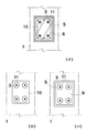
【図2】図(イ)は図1のI−I線断面図、図(ロ)は図1のII−II線矢視図、図(ハ)は図1のIII−III線矢視図である。
【符号の説明】
1…柱
2…梁
3…緊張材
4…貫通孔
5…鋼管
6…充填コンクリート
7…付着防止剤
10…第2端板
11…雌ネジ部材(定着具)[0001]
BACKGROUND OF THE INVENTION
The present invention relates to a joint structure between a column and a beam.
[0002]
[Prior art and problems]
Conventionally, the thing using the thing of a prestressed concrete structure as a beam joined to a pillar is known. The main purpose of prestressing in this case is to suppress bending of the beam against long-term loads. However, the presence of compressive stress in the beams can adversely affect strength during short-term loads such as during earthquakes. is there.
[0003]
In view of the above problems, the present invention can suppress the bending of the beam with respect to a long-term load, and also reduce the strength disadvantage of the beam when a short-term load is applied such as during an earthquake. It is an object of the present invention to provide a column-to-beam joint structure.
[0004]
[Means for Solving the Problems]
The above problem consists of a beam filled with concrete inside a steel pipe,
Tensile material is passed through the filled concrete,
This tension material penetrates the column and protrudes from the side opposite to the beam across the column, and this protruding end is provided with an end plate,
This tensile force applied to the tendon material is solved by a column-beam joint structure in which compression prestress is introduced into the filled concrete of the beam.
[0005]
In other words, in this structure, the beam is made of a steel pipe filled with concrete, and the pre-stressed concrete structure beam is introduced into the filled concrete because compression prestress is introduced by the tension material. In addition, bending of the beam with respect to a long-term load can be suppressed.
[0006]
Moreover, since this concrete is filled in the steel pipe, it can be constrained by the steel pipe by introducing prestressing compression, and can be in a three-dimensional stress state. Strength is increased. Thereby, the beam can reduce the strong disadvantage at the time of short-term load action, such as at the time of an earthquake. Moreover, the beam cross section can be reduced by this confining effect.
[0007]
In addition, in the configuration in which the tension material penetrates the column and protrudes from the side surface opposite to the beam across the column, and the end plate is provided at the protruding end, compression prestress is applied to the filled concrete in the steel pipe. Since it has been introduced, pre-stress can be easily introduced in relation to the pillar.
[0008]
In particular, when the filling concrete and steel pipes are cut off between them in the beam, compression pre-stress can be effectively introduced only into the filling concrete, and the bending of the beam against a long-term load can be reduced. While being able to suppress more effectively, the strength disadvantage of the beam at the time of short-term load action, such as at the time of an earthquake, can be reduced much more effectively.
[0009]
In addition, the tension material passed through the filled concrete penetrates the column and protrudes from the side opposite to the beam across the column, and this protruding end is provided with an end plate, and the tensile force applied to the tension material If the structure is such that the column is sandwiched between the beam filling concrete and the end plate, the beam and the column are joined, and by applying a tensile force to the tension material, the prestress is introduced into the filling concrete, and the column Can be performed at the same time, and the construction can be performed efficiently. Needless to say, additional joining means may be provided if it is not sufficient in strength to rely on the tension material alone for joining the beam and the column.
[0010]
DETAILED DESCRIPTION OF THE INVENTION
Next, embodiments of the present invention will be described with reference to the drawings. In the structure of the embodiment shown in FIGS. 1 and 2, 1 is a column and 2 is a beam.
[0011]
The
[0012]
The beam 2 is formed by filling a
[0013]
A
[0014]
By this tensile force applied to the
[0015]
The concrete of the
[0016]
In the above structure, the beam 2 is made of a
[0017]
Further, since the beam 2 is a
[0018]
Although one embodiment of the present invention has been described above, the present invention is not limited to this, and various modifications can be made without departing from the spirit of the invention. For example, in the above embodiment, the
[0019]
【The invention's effect】
Depending on the above, the column-to-beam joint structure of the present invention has the above-described configuration, so that it is possible to suppress the deflection of the beam with respect to a long-term load, and in addition, a short-term load such as during an earthquake. It is possible to reduce the disadvantage of strength of the beam at the time of action.
[Brief description of the drawings]
FIG. 1 is a cross-sectional front view showing a structure of an embodiment.
2A is a cross-sectional view taken along the line II of FIG. 1, FIG. 2B is a view taken along the line II-II of FIG. 1, and FIG. 2C is a view taken along the line III-III of FIG. It is.
[Explanation of symbols]
DESCRIPTION OF
Claims (1)
充填コンクリートには緊張材が通され、
この緊張材は、柱を貫通し、柱を挟んで梁と反対側の側面から突出され、この突出端には端板が備えられており、
この緊張材に付与した引張り力によって、梁の充填コンクリートに圧縮のプレストレスが導入されており、かつ、
前記CFT梁を構成している鋼管の端部が柱から離間し、該CFT梁の充填コンクリートが該鋼管の端部から柱側に突出して梁端崩壊するようになされていると共に、
柱のコンクリートと梁のコンクリートとが一体打ちされていることを特徴とする柱と梁の接合構造。 The beam consists of a CFT beam filled with concrete as a formwork, discarding the steel pipe inside the steel pipe,
Tensile material is passed through the filled concrete,
This tension material penetrates the column and protrudes from the side opposite to the beam across the column, and this protruding end is provided with an end plate,
By the tensile force applied to this tendon, compression pre-stress is introduced into the concrete filling the beam, and
The end of the steel pipe constituting the CFT beam is separated from the column, and the filled concrete of the CFT beam protrudes from the end of the steel pipe to the column side so that the beam end collapses .
Column and beam joint structure characterized in that the concrete of the column and the concrete of the beam are integrally cast .
Priority Applications (1)
| Application Number | Priority Date | Filing Date | Title |
|---|---|---|---|
| JP00549999A JP4094149B2 (en) | 1999-01-12 | 1999-01-12 | Column and beam joint structure |
Applications Claiming Priority (1)
| Application Number | Priority Date | Filing Date | Title |
|---|---|---|---|
| JP00549999A JP4094149B2 (en) | 1999-01-12 | 1999-01-12 | Column and beam joint structure |
Publications (2)
| Publication Number | Publication Date |
|---|---|
| JP2000204657A JP2000204657A (en) | 2000-07-25 |
| JP4094149B2 true JP4094149B2 (en) | 2008-06-04 |
Family
ID=11612925
Family Applications (1)
| Application Number | Title | Priority Date | Filing Date |
|---|---|---|---|
| JP00549999A Expired - Fee Related JP4094149B2 (en) | 1999-01-12 | 1999-01-12 | Column and beam joint structure |
Country Status (1)
| Country | Link |
|---|---|
| JP (1) | JP4094149B2 (en) |
Cited By (1)
| Publication number | Priority date | Publication date | Assignee | Title |
|---|---|---|---|---|
| CN103924681A (en) * | 2014-04-14 | 2014-07-16 | 北京工业大学 | Prestress connected precast concrete beam rectangular steel tube concrete column node |
Families Citing this family (12)
| Publication number | Priority date | Publication date | Assignee | Title |
|---|---|---|---|---|
| JP5211258B1 (en) * | 2012-08-17 | 2013-06-12 | 黒沢建設株式会社 | Buildings using steel columns with seismic prestressing |
| JP6205115B2 (en) * | 2012-09-27 | 2017-09-27 | 東急建設株式会社 | Corbels and buildings |
| CN106703190A (en) * | 2017-02-28 | 2017-05-24 | 中国建筑股份有限公司 | Prefabricating beam column joint structure containing prestressing pore path and construction method thereof |
| CN107829495A (en) * | 2017-11-15 | 2018-03-23 | 武汉理工大学 | Beam-ends power consumption restricted type prestressing force prefabricated concrete structure and its construction method |
| CN108755954B (en) * | 2018-05-25 | 2020-04-17 | 西安建筑科技大学 | Unilateral prestressing force full assembled is from restoring to throne steel frame node |
| CN109113189B (en) * | 2018-09-18 | 2020-04-17 | 西安建筑科技大学 | Self-resetting circular steel tube concrete frame beam column joint with web plate provided with energy dissipation piece |
| CN111945882B (en) * | 2020-08-18 | 2022-03-01 | 中交鹭建有限公司 | Prestressed steel strand reinforced concrete beam column joint structure and construction method thereof |
| CN111980150A (en) * | 2020-09-01 | 2020-11-24 | 湖南大学 | Assembled prestressing force anti frame construction that collapses in succession |
| CN112523378B (en) * | 2020-12-23 | 2022-03-18 | 东南大学 | Self-resetting energy-consuming steel beam capable of eliminating frame expansion effect and construction method thereof |
| CN115198966B (en) * | 2021-04-09 | 2024-08-16 | 上海砼邦建设工程有限公司 | Construction method of prestress prefabricated superposed frame beam |
| CN115749260A (en) * | 2022-11-30 | 2023-03-07 | 中建二局西北投资建设有限公司 | Beam column node template fixing system |
| CZ2022528A3 (en) * | 2022-12-15 | 2023-11-29 | Peem, Spol. S R. O. | A reinforced column with one bracket and parallel reinforcement |
-
1999
- 1999-01-12 JP JP00549999A patent/JP4094149B2/en not_active Expired - Fee Related
Cited By (1)
| Publication number | Priority date | Publication date | Assignee | Title |
|---|---|---|---|---|
| CN103924681A (en) * | 2014-04-14 | 2014-07-16 | 北京工业大学 | Prestress connected precast concrete beam rectangular steel tube concrete column node |
Also Published As
| Publication number | Publication date |
|---|---|
| JP2000204657A (en) | 2000-07-25 |
Similar Documents
| Publication | Publication Date | Title |
|---|---|---|
| JP4094149B2 (en) | Column and beam joint structure | |
| US20050050837A1 (en) | Meshed (porous) steel pipe/tube used as concrete reinforcement | |
| JP2000144905A (en) | Mixed structural beam | |
| KR101043240B1 (en) | Continuation structure of prestressed concrete girder bridge | |
| JP2001040881A (en) | Reinforcing structure for column-beam joint | |
| JP2973812B2 (en) | Joint structure between steel members and concrete members | |
| JP4447632B2 (en) | Beam and beam-column joint structure and method of joining the same | |
| JP2757043B2 (en) | Reinforced concrete columns | |
| JP2000096834A (en) | Reinforcing structure of concrete member | |
| JP2716508B2 (en) | Column and beam joint structure | |
| JPH07116790B2 (en) | Precast concrete beams | |
| JPH0520817Y2 (en) | ||
| JP2762906B2 (en) | RC frame | |
| JPH0674620B2 (en) | Reinforced concrete columns covered with steel pipes | |
| JP2000170263A (en) | Panel point structure of steel-concrete composite structure | |
| KR102149486B1 (en) | Truss for preventing buckling of joints | |
| JP2004092248A (en) | Joint metal of anchor bar, joint structure using the same and joining method used for the same | |
| JP2973985B2 (en) | RC column and steel beam joint structure | |
| JP2878382B2 (en) | Frame structure of structure consisting of PC steel column and PC steel beam or PS steel beam | |
| JP2984870B2 (en) | Column and beam joint toughness reinforcement structure | |
| JPH073883A (en) | Un-bonded brace | |
| JPS62378Y2 (en) | ||
| JPH04124354A (en) | Packed tube-concrete composite column | |
| JP3534978B2 (en) | Method of introducing tensile prestress of steel member, steel member and method of reinforcing the same | |
| JPH0478771B2 (en) |
Legal Events
| Date | Code | Title | Description |
|---|---|---|---|
| A621 | Written request for application examination |
Free format text: JAPANESE INTERMEDIATE CODE: A621 Effective date: 20051226 |
|
| A977 | Report on retrieval |
Free format text: JAPANESE INTERMEDIATE CODE: A971007 Effective date: 20070614 |
|
| A131 | Notification of reasons for refusal |
Free format text: JAPANESE INTERMEDIATE CODE: A131 Effective date: 20070626 |
|
| A521 | Written amendment |
Free format text: JAPANESE INTERMEDIATE CODE: A523 Effective date: 20070827 |
|
| A131 | Notification of reasons for refusal |
Free format text: JAPANESE INTERMEDIATE CODE: A131 Effective date: 20071030 |
|
| A521 | Written amendment |
Free format text: JAPANESE INTERMEDIATE CODE: A523 Effective date: 20071218 |
|
| TRDD | Decision of grant or rejection written | ||
| A01 | Written decision to grant a patent or to grant a registration (utility model) |
Free format text: JAPANESE INTERMEDIATE CODE: A01 Effective date: 20080304 |
|
| A61 | First payment of annual fees (during grant procedure) |
Free format text: JAPANESE INTERMEDIATE CODE: A61 Effective date: 20080305 |
|
| FPAY | Renewal fee payment (event date is renewal date of database) |
Free format text: PAYMENT UNTIL: 20110314 Year of fee payment: 3 |
|
| R150 | Certificate of patent or registration of utility model |
Free format text: JAPANESE INTERMEDIATE CODE: R150 |
|
| LAPS | Cancellation because of no payment of annual fees |