JP4093108B2 - Check valve and brake actuator using the check valve - Google Patents
Check valve and brake actuator using the check valve Download PDFInfo
- Publication number
- JP4093108B2 JP4093108B2 JP2003135544A JP2003135544A JP4093108B2 JP 4093108 B2 JP4093108 B2 JP 4093108B2 JP 2003135544 A JP2003135544 A JP 2003135544A JP 2003135544 A JP2003135544 A JP 2003135544A JP 4093108 B2 JP4093108 B2 JP 4093108B2
- Authority
- JP
- Japan
- Prior art keywords
- check valve
- valve
- ball
- coil spring
- spring
- Prior art date
- Legal status (The legal status is an assumption and is not a legal conclusion. Google has not performed a legal analysis and makes no representation as to the accuracy of the status listed.)
- Expired - Fee Related
Links
Images


Classifications
-
- B—PERFORMING OPERATIONS; TRANSPORTING
- B60—VEHICLES IN GENERAL
- B60T—VEHICLE BRAKE CONTROL SYSTEMS OR PARTS THEREOF; BRAKE CONTROL SYSTEMS OR PARTS THEREOF, IN GENERAL; ARRANGEMENT OF BRAKING ELEMENTS ON VEHICLES IN GENERAL; PORTABLE DEVICES FOR PREVENTING UNWANTED MOVEMENT OF VEHICLES; VEHICLE MODIFICATIONS TO FACILITATE COOLING OF BRAKES
- B60T8/00—Arrangements for adjusting wheel-braking force to meet varying vehicular or ground-surface conditions, e.g. limiting or varying distribution of braking force
- B60T8/32—Arrangements for adjusting wheel-braking force to meet varying vehicular or ground-surface conditions, e.g. limiting or varying distribution of braking force responsive to a speed condition, e.g. acceleration or deceleration
- B60T8/34—Arrangements for adjusting wheel-braking force to meet varying vehicular or ground-surface conditions, e.g. limiting or varying distribution of braking force responsive to a speed condition, e.g. acceleration or deceleration having a fluid pressure regulator responsive to a speed condition
- B60T8/341—Systems characterised by their valves
-
- B—PERFORMING OPERATIONS; TRANSPORTING
- B60—VEHICLES IN GENERAL
- B60T—VEHICLE BRAKE CONTROL SYSTEMS OR PARTS THEREOF; BRAKE CONTROL SYSTEMS OR PARTS THEREOF, IN GENERAL; ARRANGEMENT OF BRAKING ELEMENTS ON VEHICLES IN GENERAL; PORTABLE DEVICES FOR PREVENTING UNWANTED MOVEMENT OF VEHICLES; VEHICLE MODIFICATIONS TO FACILITATE COOLING OF BRAKES
- B60T17/00—Component parts, details, or accessories of power brake systems not covered by groups B60T8/00, B60T13/00 or B60T15/00, or presenting other characteristic features
- B60T17/04—Arrangements of piping, valves in the piping, e.g. cut-off valves, couplings or air hoses
-
- F—MECHANICAL ENGINEERING; LIGHTING; HEATING; WEAPONS; BLASTING
- F16—ENGINEERING ELEMENTS AND UNITS; GENERAL MEASURES FOR PRODUCING AND MAINTAINING EFFECTIVE FUNCTIONING OF MACHINES OR INSTALLATIONS; THERMAL INSULATION IN GENERAL
- F16K—VALVES; TAPS; COCKS; ACTUATING-FLOATS; DEVICES FOR VENTING OR AERATING
- F16K15/00—Check valves
- F16K15/02—Check valves with guided rigid valve members
- F16K15/04—Check valves with guided rigid valve members shaped as balls
- F16K15/042—Check valves with guided rigid valve members shaped as balls with a plurality of balls
-
- F—MECHANICAL ENGINEERING; LIGHTING; HEATING; WEAPONS; BLASTING
- F16—ENGINEERING ELEMENTS AND UNITS; GENERAL MEASURES FOR PRODUCING AND MAINTAINING EFFECTIVE FUNCTIONING OF MACHINES OR INSTALLATIONS; THERMAL INSULATION IN GENERAL
- F16K—VALVES; TAPS; COCKS; ACTUATING-FLOATS; DEVICES FOR VENTING OR AERATING
- F16K15/00—Check valves
- F16K15/02—Check valves with guided rigid valve members
- F16K15/04—Check valves with guided rigid valve members shaped as balls
- F16K15/044—Check valves with guided rigid valve members shaped as balls spring-loaded
-
- Y—GENERAL TAGGING OF NEW TECHNOLOGICAL DEVELOPMENTS; GENERAL TAGGING OF CROSS-SECTIONAL TECHNOLOGIES SPANNING OVER SEVERAL SECTIONS OF THE IPC; TECHNICAL SUBJECTS COVERED BY FORMER USPC CROSS-REFERENCE ART COLLECTIONS [XRACs] AND DIGESTS
- Y10—TECHNICAL SUBJECTS COVERED BY FORMER USPC
- Y10T—TECHNICAL SUBJECTS COVERED BY FORMER US CLASSIFICATION
- Y10T137/00—Fluid handling
- Y10T137/7722—Line condition change responsive valves
- Y10T137/7837—Direct response valves [i.e., check valve type]
- Y10T137/7904—Reciprocating valves
- Y10T137/7922—Spring biased
- Y10T137/7927—Ball valves
- Y10T137/7928—With follower
Description
【0001】
【発明の属する技術分野】
本発明は、流体の一方向の流れのみを許容するチェック弁に関し、特に油圧ポンプの吐出側のチェック弁に好適である。
【0002】
【従来の技術】
従来、弁座面にボールが接離して流体通路を開閉するチェック弁においては、コイルばねによってボール(弁体)が弁座面に向かって(すなわち、閉弁方向に)付勢されている。
【0003】
そして、弁座面よりも上流側の圧力が弁座面よりも下流側の圧力よりも所定圧以上高くなると、コイルばねの付勢力に抗してボールが弁座面から離されて開弁し、流体が所定の一方向に流れるようになっている。また、この開弁時には、ボールは流体の流れによる力とコイルばねの付勢力とを受け、ボールはそれらの力がバランスする位置に移動する。
【0004】
【発明が解決しようとする課題】
しかしながら、上記従来のチェック弁を例えばポンプの吐出側に設置した場合、ポンプの吐出圧の脈動によってボールに作用する流体の流れによる力が変動してしまう。そのため、ボールの位置が変動してボールが振動し、このボールの振動により圧力脈動が増幅されてしまうという問題が発生していた。
【0005】
本発明は上記の点に鑑みてなされたもので、弁座面に弁体が接離して流体通路を開閉するチェック弁において、弁体の振動により圧力脈動が増幅されることを防止ないしは抑制することを目的とする。
【0006】
【課題を解決するための手段】
上記目的を達成するため、請求項1に記載の発明では、流体通路(1502、1521)を形成するケース部材(1500、1520)と、ケース部材に形成されると共に、流体通路の途中に配置された弁座面(1503)と、弁座面よりも下流側の流体通路中に配置されると共に、弁座面と接離して流体通路を開閉する弁体(1540)と、ケース部材内に配置されると共に、弁体を閉弁方向に付勢する圧縮コイルばね(1560)とを備えるチェック弁において、弁体に対する弁座面よりも上流側の流体の圧力作用向きをXとしたとき、ケース部材には、圧力作用向きXに対して垂直方向への弁体の移動範囲を規制する壁面(1526a)が形成され、圧縮コイルばねの付勢力を弁体に伝達するロッド(1580)が弁体と圧縮コイルばねとの間に配置され、ロッドにより、弁体に伝達される付勢力の向きが圧力作用向きXに対して斜めになるように変換されて、弁体が壁面に向かって付勢されるように構成され、さらに、ロッドは圧縮コイルばねの端部と接するばね受け面(1582、1582a、1582b)と該バネ受け面から突出するばね案内部(1583)を有し、ばね受け面は、ロッドに対する圧縮コイルばねの付勢力作用向きに沿って拡がる形状であることを特徴とする。
【0012】
これによると、弁体に伝達された付勢力の分力により弁体が壁面に向かって付勢されるため、開弁状態時には弁体が壁面に押し付けられて弁体の振動がおさえられる。従って、弁体の振動が防止ないしは抑制され、圧力脈動の増幅も防止ないしは抑制される。
【0013】
ところで、図6に示すように、ロッド580におけるばね受け面583がコイルばね560の付勢力作用向きに対して垂直な平面である場合、以下のような問題が発生する恐れがある。すなわち、組み付け時或いは作動中に、コイルばね560の中心軸とロッド580の中心軸とがずれてしまった場合、ロッド580が傾いてしまうため、コイルばね560の付勢力が正しく伝達されなかったり、また、コイルばね560に偏荷重が長期間かかってばね寿命が低下する恐れがある。
【0014】
これに対し、請求項1の発明では、ロッドのばね受け面を、圧縮コイルばねの付勢力作用向きに沿って拡がる形状にしているため、ばね受け面の調芯作用により、圧縮コイルばねの中心軸とロッドの中心軸とを自動的に一致させることができる。従って、圧縮コイルばねの付勢力を正しく伝達できると共に、圧縮コイルばねに対する偏荷重を少なくしてばね寿命の低下を防止することができる。
【0015】
請求項2に記載の発明のようにばね受け面(1582)を円錐面にしてもよいし、請求項3に記載の発明のようにばね受け面(1582a)を凹曲面にしてもよいし、さらには請求項4に記載の発明のようにばね受け面(1582b)を凸曲面にしてもよい。
【0016】
また、請求項5に記載の発明のように、マスタシリンダ(3)からのブレーキ液圧をホイールシリンダ(4、5)に伝達し、車輪に対して制動力を発生させるように構成され、ホイールシリンダ側のブレーキ液を吸入すると共に吸入したブレーキ液をマスタシリンダ側に吐出するポンプ(10)を備えてなるブレーキアクチュエータにおいて、請求項1ないし4のいずれか1つに記載のチェック弁を、ポンプの吐出側に配置することができる。
【0017】
なお、上記各手段の括弧内の符号は、後述する実施形態に記載の具体的手段との対応関係を示すものである。
【0018】
【発明の実施の形態】
以下、本発明を図に示す実施形態に基づいて説明する。
まず、本発明の実施形態を説明するに先立ち、本発明の基本的な構成を示す参考例について説明する。
【0019】
(参考例1)
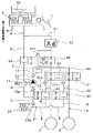
図1に、本発明の参考例1におけるチェック弁を用いた車両用ブレーキ装置のブレーキ配管概略図を示す。以下、ブレーキ装置の基本構成を図1に基づいて説明する。本例では前輪駆動の4輪車において、右前輪−左後輪、左前輪−右後輪の各配管系統を備えるX配管の油圧回路を構成するブレーキ装置を示している。
【0020】
図1に示すように、ブレーキペダル1は倍力装置2と接続されており、この倍力装置2によりブレーキ踏力等が倍力される。倍力装置2は、倍力された踏力をマスタシリンダ3に伝達するプッシュロッド等を有しており、このプッシュロッドがマスタシリンダ3に配設されたマスタピストンを押圧することによりマスタシリンダ圧が発生する。なお、これらブレーキペダル1、倍力装置2及びマスタシリンダ3がブレーキ液圧発生手段に相当する。
【0021】
また、このマスタシリンダ3には、マスタシリンダ3内にブレーキ液を供給したり、マスタシリンダ3内の余剰ブレーキ液を貯留するマスタリザーバ3aが接続されている。
【0022】
マスタシリンダ圧は、アンチロックブレーキ装置(以下、ABSという)などを介して右前輪FR用のホイールシリンダ4及び左後輪RL用のホイールシリンダ5へ伝達されている。以下の説明は、右前輪FR及び左後輪RL側について行うが、第2の配管系統である左前輪FL及び右後輪RR側についても全く同様であるため、説明は省略する。
【0023】
このブレーキ装置はマスタシリンダ3に接続する管路(主管路)Aを備えており、この管路Aには比例制御弁(PV:プロポーショニングバルブ)22が備えられている。そして、この比例制御弁22によって管路Aは2部位に分けられている。すなわち管路Aは、マスタシリンダ3から比例制御弁22までの間においてマスタシリンダ圧を受ける管路A1と、比例制御弁22から各ホイールシリンダ4、5までの間の管路A2に分けられる。
【0024】
この比例制御弁22は、通常、正方向にブレーキ液が流動する際には、ブレーキ液の基準圧を所定の減衰比率をもって下流側に伝達する作用を有している。そして、図1に示すように、比例制御弁22を逆接続した場合、管路A2側が基準圧となる。
【0025】
また、管路A2において、管路Aは2つに分岐しており、一方にはホイールシリンダ4へのブレーキ液圧の増圧を制御する増圧制御弁30が備えられ、他方にはホイールシリンダ5へのブレーキ液圧の増圧を制御する増圧制御弁31が備えられている。
【0026】
これら増圧制御弁30、31は、ABS用の電子制御装置(以下、ECUという)により連通・遮断状態を制御できる2位置弁として構成されている。そして、この2位置弁が連通状態に制御されているときには、マスタシリンダ圧あるいはポンプのブレーキ液の吐出によるブレーキ液圧を各ホイールシリンダ4、5に加えることができる。
【0027】
なお、ABS制御が実行されていないノーマルブレーキ時には、これら第1、第2の増圧制御弁30、31は常時連通状態に制御されている。増圧制御弁30、31には、それぞれチェック弁30a、31aが並列に設けられており、ブレーキ踏み込みを止めてABS制御が終了したときにおいてホイールシリンダ4、5側からブレーキ液を排除するようになっている。
【0028】
また、第1、第2の増圧制御弁30、31と各ホイールシリンダ4、5との間における管路Aとリザーバ20のリザーバ孔20aとを結ぶ管路Bには、ABS用のECUにより連通・遮断状態を制御できる減圧制御弁32、33がそれぞれ配設されている。これらの減圧制御弁32、33はノーマルブレーキ状態(ABS非作動時)では、常時遮断状態とされている。
【0029】
管路Aの比例制御弁22と増圧制御弁30、31とリザーバ20のリザーバ孔20aとを結ぶ管路Cには、回転式ポンプ10が吸入側チェック弁10aと吐出側チェック弁50とに挟まれて配設されている。そして、ABS制御が実行されると、ホイールシリンダ4、5の減圧時にホイールシリンダ4、5から排出されたブレーキ液がリザーバ20に流入し、回転式ポンプ10は管路Cを介してリザーバ20内のブレーキ液を汲み取り、管路A2へ吐出する。なお、回転式ポンプ10の吐出側に設けたチェック弁50が本発明になるチェック弁であり、その詳細については後述する。
【0030】
上記の回転式ポンプ10にはモータ11が接続されており、このモータ11によって回転式ポンプ10は駆動される。この回転式ポンプ10は、トロコイドポンプ等の内接歯車型の回転式ポンプである。
【0031】
また、回転式ポンプ10が吐出したブレーキ液の脈動を緩和するために、管路Cのうち回転式ポンプ10の吐出側にはダンパ12が配設されている。そして、リザーバ20と回転式ポンプ10の間と、マスタシリンダ3とを接続するように管路(補助管路)Dが設けられており、回転式ポンプ10は、TRC時等にこの管路Dを介して管路A1のブレーキ液を汲み取り、管路A2へ吐出することによってホイールシリンダ4、5におけるホイールシリンダ圧をマスタシリンダ圧よりも高くして車輪制動力を高める。なお、比例制御弁22はこの際のマスタシリンダ圧とホイールシリンダ圧との差圧を保持する。
【0032】
そして、この管路Dには制御弁34が設けられており、この制御弁34はノーマルブレーキ時には常時遮断状態とされている。なお、管路Dから伝えられる液圧により管路Cからリザーバ20へ逆流しないように、管路C及び管路Dの接続部とリザーバ20の間にはチェック弁21が配設されている。
【0033】
さらに、管路Aのうち、比例制御弁22と増圧制御弁30、31との間には、制御弁40が備えられている。この制御弁40は、通常は連通状態にされている2位置弁であり、マスタシリンダ圧が所定圧よりも低いときにホイールシリンダ4、5に急ブレーキをかける時、或いはTRC時に遮断され、マスタシリンダ側とホイールシリンダ側との差圧を保つようになっている。
【0034】
なお、制御弁40には安全弁40aが並列に設けられており、制御弁40が遮断状態の時に、マスタシリンダ3側からホイールシリンダ4、5側にブレーキ液圧を加えられるようになっている。
【0035】
次に、吐出側チェック弁50について詳細に説明する。なお、図2はチェック弁50の閉弁状態を示す断面図、図3は図2のスリーブ520のE−E断面図、図4はチェック弁50の開弁状態を示す断面図である。
【0036】
図2において、上記チェック弁50は、ABSのケーシング60に、上記したABSの各種弁や回転式ポンプ10等と共に組み付けられている。
【0037】
具体的には、ケーシング60の段付穴61、62にチェック弁50が挿入され、その際、チェック弁50のシート500をケーシング60の大径側段付穴61に圧入してチェック弁50をケーシング60に固定するようにしている。
【0038】
一方、ケーシング60の小径側段付穴62とチェック弁50のスリーブ520の外周面との間には、ブレーキ液の通路となる空間63が形成されている。この空間63はケーシング60に形成された通路穴64と連通している。なお、この通路穴64は、ダンパ12が配設された側の管路C(図1参照)の一部をなすものである。
【0039】
そして、回転式ポンプ10から吐出されたブレーキ液は、チェック弁50内を通って空間63に流入し、さらに通路穴64へと流れるようになっている。
【0040】
図2及び図3において、チェック弁50は、シート500、スリーブ520、第1、第2のボール540、550、コイルばね560、及びOリング570から構成されている。これらの構成部分のうち、Oリング570はゴム製であり、その他はいずれも金属製である。なお、コイルばね560は、より詳細には円筒圧縮コイルばねである。
【0041】
ケース部材を構成するシート500の外形は段付の略円筒形状になっており、大径部の外周面にはOリング570が挿入される溝501が形成され、小径部の外周面には径外方に向かって突出する突起部502が形成されている。
【0042】
また、シート500の径方向中心部には、軸方向に貫通した円形の通路穴503が形成されている。この通路穴503はブレーキ液の通路となるもので、この通路穴503の下流側開口部に円錐状の弁座面504が形成されている。
【0043】
この弁座面504よりも下流側には、弁体をなす第1のボール540が弁座面504に対向して配置されている。そして、弁座面504よりも上流側のブレーキ液圧が、この第1のボール540に対してそれを開弁させるように作用している。なお、この第1のボール540に対して弁座面504よりも上流側のブレーキ液圧が作用する向きXを、以下、圧力作用向きXという。因みに、圧力作用向きXは、通路穴503及び弁座面504の軸線と平行である。
【0044】
ケース部材を構成する有底円筒状のスリーブ520には段付の中空部が形成されており、具体的には、3つの円柱状の中空部521〜523が形成されている。これらの中空部521〜523のうち開口端部側の第1中空部521はブレーキ液の通路となるもので、スリーブ520の径方向中心部に形成され、この第1中空部521を囲む薄肉の円筒部524に、この円筒部524の内外を連通させてブレーキ液の通路となる開口部525が1つ形成されている。そして、この開口部525は、後述するばね力F(図4参照)の分力のうち圧力作用向きXに対して垂直方向の分力F1の向きに配置されている。
【0045】
第1中空部521よりも底部側に位置する第2中空部522は、第1中空部521よりも小径で、かつスリーブ520の軸と同軸に形成されている。そして、圧力作用向きXに対して垂直方向に位置する内周側壁面526と、圧力作用向きXの延長線側に位置する底部壁面527とにより、第2中空部522が囲まれており、この内周側壁面526と第2中空部522の底部壁面527とにより第1のボール540の移動範囲を規制するようになっている。
【0046】
第2中空部522よりも底部側に位置する第3中空部523は、第2中空部522よりも小径で、かつスリーブ520の軸に対して偏芯して形成され、この第3中空部523内に第2のボール550とコイルばね560が配置されている。
【0047】
また、この第2のボール550はコイルばね560の付勢力を第1のボール540に伝達する伝達部材をなすもので、コイルばね560と第1のボール540との間に配置されている。そして、第1のボール540には、それを閉弁させる向きにコイルばね560の力が第2のボール550を介して作用するようになっている。
【0048】
そして、第1、第2のボール540、550及びコイルばね560をスリーブ520内に収納した後、円筒部524の開口端部側を3箇所かしめて突起部502と係合させることにより、シート500とスリーブ520が一体化されている。
【0049】
次に、上記構成になるチェック弁50の作動を図2〜図4に基づいて説明する。ABS制御時等には回転式ポンプ10(図1参照)が作動され、吸入したブレーキ液は回転式ポンプ10により高圧化されて吐出される。吐出されたブレーキ液は吐出側チェック弁50の通路穴503に流入し、第1のボール540には圧力作用向きXにブレーキ液圧が作用する。
【0050】
そして、コイルばね560の付勢力に抗して第1のボール540が開弁方向に移動されると(図4参照)、通路穴503に流入したブレーキ液は、第1中空部521、開口部525、および空間63を通って通路穴64に流入する。
【0051】
ここで、コイルばね560および第2のボール550が配置された第3中空部523が、通路穴503の軸線に対して偏芯しているため、第1のボール540の中心点Y1と第2のボール550の中心点Y2とを結ぶ線が、圧力作用向きXに対して斜め(非平行)になる。従って、コイルばね560から第1のボール540に伝達されるばね力Fの向きが第2のボール550によって変換され、第1のボール540に伝達されるばね力Fの向きは圧力作用向きXに対して斜めになる。
【0052】
従って、図4の開弁状態時には、ばね力Fの分力のうち圧力作用向きXに対して垂直方向の分力F1(以下、垂直方向分力F1という)によって、第1のボール540は内周側壁面526に押し付けられ、第1のボール540の振動がおさえられる。
【0053】
これにより、第1のボール540に作用するブレーキ液の流れによる力がポンプの吐出圧の脈動によって変動しても、第1のボール540の振動が防止されるため、第1のボール540の振動による圧力脈動の増幅も防止される。
【0054】
ここで、図2に示す閉弁状態での第1のボール540の中心点Y1と第2のボール550の中心点Y2とを結ぶ線の、圧力作用向きXに対する傾斜角度θ、換言すると、閉弁状態での第1のボール540に伝達される付勢力の向きと、圧力作用向きXとのなす角度の、適切な範囲について検討した。
【0055】
図5はその結果を示すもので、傾斜角度θを4度にした場合は、第1のボール540の振動抑制効果が得られず、また、傾斜角度θを50度にした場合は、作動が不安定になって閉弁しない状況が発生した。一方、傾斜角度θを8度から45度にした場合は、確実な流体通路の開閉機能を維持しつつ、第1のボール540の振動抑制効果が得られた。
【0056】
また、ポンプの吐出圧が高くなると第1のボール540はリフト量が増加して底部壁面527にも当接する。従って、第1のボール540は内周側壁面526及び底部壁面527に押し付けられ、第1のボール540の振動がより確実におさえられる。
【0057】
さらに、垂直方向分力F1の向きに開口部525を配置しているため、通路穴503から第1中空部521を通って開口部525に向かうブレーキ液の流れの向きが垂直方向分力F1の向きと一致し、開口部525に向かうブレーキ液の流れによる力によっても第1のボール540が内周側壁面526に押し付けられ、従って、第1のボール540の振動がより確実におさえられる。
【0058】
なお、開口部525は垂直方向分力F1の向きに配置するのが最も効果的であるが、スリーブ520の軸線に対して垂直な断面(図3)における垂直方向分力F1の向きを中心にして、±90°以内(望ましくは±45°以内)の位置に配置してもよい。
【0059】
また、本参考例1では、スリーブ520の小型化のために第2のボール550は第1のボール540よりも小さいものを用いているが、両ボール540、550は同サイズであってもよい。そして、両ボール540、550を同サイズにした場合は、両ボール540、550をスリーブ520内に収納する際に挿入順序を考慮する必要がなく、両ボール540、550の誤組み付けを防止できる。
【0060】
(参考例2)
図6は本発明の参考例2を示すもので、参考例1の第2のボール550の代わりにロッド580を用いており、その他の点は参考例1と同一である。
【0061】
図6はチェック弁の閉弁状態を示すもので、コイルばね560の付勢力を第1のボール540に伝達する伝達部材としてのロッド580は略段付円柱状になっている。
【0062】
より詳細には、ロッド580は、円柱部581と、円柱部581の一端側に形成されて、第1のボール540に当接する円錐状のボール当接面582と、円柱部581の他端側に形成されて、コイルばね560の端部と接するばね受け面583と、ばね受け面583から突出してコイルばね560の内部に挿入される円柱状のばね案内部584とを有する。
【0063】
これによれば、コイルばね560から第1のボール540に作用するばね力Fの向きは圧力作用向きXに対して斜めになり、垂直方向分力F1によって第1のボール540は内周側壁面526に押し付けられ、第1のボール540の振動がおさえられる。
【0064】
また、閉弁状態で第1のボール540とロッド580のボール当接面582とが接する点を閉弁時当接点Zとしたとき、閉弁時当接点Zと第1のボール540の中心点Y1とを結ぶ線の、圧力作用向きXに対する傾斜角度を、8度から45度に設定することにより、確実な流体通路の開閉機能を維持しつつ、第1のボール540の振動抑制効果を得ることができる。
【0065】
なお、本参考例において、ロッド580のボール当接面582を半球状にしてもよい。
【0066】
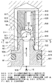
(第1実施形態)
本発明の第1実施形態のチェック弁150について図7に基づいて説明する。図7はチェック弁150の閉弁状態を示す断面図である。このチェック弁150は、上記参考例1のチェック弁50と同様に回転式ポンプ10(図1参照)の吐出側のチェック弁として用いられる。なお、参考例1と同一もしくは均等部分には同一の符号を付し、その説明を省略する。
【0067】
このチェック弁150は、シート1500、スリーブ1520、ボール1540、コイルばね1560、及びロッド1580から構成されている。これらの構成部分はいずれも金属製である。
【0068】
ケース部材を構成するシート1500の外形は段付の略円筒形状になっており、小径部の外周面には径外方に向かって突出する突起部1501が形成されている。また、シート1500の径方向中心部には、軸方向に貫通した円形の通路穴1502が形成されている。この通路穴1502はブレーキ液の通路となるもので、この通路穴1502の下流側開口部に円錐状の弁座面1503が形成されている。
【0069】
この弁座面1503よりも下流側には、弁体をなすボール1540が弁座面1503に対向して配置されている。そして、弁座面1503よりも上流側のブレーキ液圧が、このボール1540に対してそれを開弁させるように作用している。なお、このボール1540に対して、弁座面1503よりも上流側のブレーキ液圧が作用する向きXを、以下、圧力作用向きXという。因みに、圧力作用向きXは、通路穴1502及び弁座面1503の軸線と平行である。
【0070】
ケース部材を構成する有底円筒状のスリーブ1520は、例えば冷間圧延鋼板(SPCD)をプレス成形して、3つの中空部1521〜1523が形成されている。これらの中空部1521〜1523のうち、スリーブ1520の開口端部側に位置する円柱状の第1中空部1521は、ブレーキ液の通路となるものである。この第1中空部1521を囲む円筒壁面1524に、この円筒壁面1524の内外を連通させてブレーキ液の通路となる開口部1525が1つ形成されている。そして、この開口部1525は、後述するばね力Fの分力のうち圧力作用向きXに対して垂直方向の分力F1の向きに配置されている。
【0071】
3つの中空部1521〜1523のうちスリーブ1520の最も底部側に位置する円柱状の第3中空部1523は、第1中空部1521よりも小径で、かつ第1中空部1521の軸に対して偏芯している。
【0072】
第1中空部1521と第3中空部1523との間に第2中空部1522が形成されており、この第2中空部1522を囲む壁面1526のうち、垂直方向分力F1の向きに位置する壁面、すなわち開口部1525が位置する側の壁面1526aは、圧力作用向きXに対して約45°傾斜している。そして、この開口部1525側の壁面1526aにより、圧力作用向きXへのボール1540の移動範囲、及び、垂直方向分力F1の向きへのボール1540の移動範囲を規制するようになっている。
【0073】
第3中空部1523内にはコイルばね1560が配置されており、このコイルばね1560とボール1540との間にロッド1580が配置されている。なお、コイルばね1560は、より詳細には、円筒圧縮コイルばねである。
【0074】
ロッド1580は、例えば炭素鋼よりなり、コイルばね1560の付勢力をボール1540に伝達する伝達部材をなすものである。より詳細には、ロッド1580は、ボール1540と接する半球状のボール当接面1581と、コイルばね1560の端部と接するばね受け面1582と、ばね受け面1582から突出してコイルばね1560の内部に挿入される円柱状のばね案内部1583を有する。ここで、ばね受け面1582は、ロッド1580に対するコイルばね1560の付勢力作用向きに沿って拡がる形状であり、本例では円錐面になっている。
【0075】
チェック弁150の組み付けに際しては、スリーブ1520の開口端部側を上にした状態で、まずコイルばね1560を第3中空部1523に挿入し、ロッド1580のばね案内部1583をコイルばね1560に挿入し、さらに、ボール1540をスリーブ1520内に収納した後、スリーブ1520の開口端部にシート1500の小径部を挿入する。そして、スリーブ1520の開口端部側を3箇所かしめてシート1500とスリーブ1520とを一体化する。
【0076】
ここで、ロッド1580のばね案内部1583をコイルばね1560に挿入することにより、コイルばね1560の軸線に対して直交する方向への、コイルばね1560とロッド1580の相対移動が防止される。これにより、チェック弁組み付け時において、ボール1540をスリーブ1520内に挿入する際に、ロッド1580がコイルばね1560から脱落するのを防止することができる。
【0077】
完成したチェック弁150は、ABSのケーシング60に、ABSの各種弁や回転式ポンプ10等と共に組み付けられる。具体的には、ケーシング60の段付穴61、62にチェック弁150が挿入され、その際、チェック弁150のシート1500をケーシング60の大径側段付穴61に圧入することにより、チェック弁150をケーシング60に気密的に固定するようにしている。
【0078】
ケーシング60の小径側段付穴62とチェック弁150のスリーブ1520の外周面との間には、ブレーキ液の通路となる空間63が形成されている。この空間63はケーシング60に形成された通路穴64と連通している。なお、この通路穴64は、ダンパ12が配設された側の管路C(図1参照)の一部をなすものである。そして、回転式ポンプ10から吐出されたブレーキ液は、チェック弁150内を通って空間63に流入し、さらに通路穴64へと流れるようになっている。
【0079】
次に、上記構成になるチェック弁150の作動を図7に基づいて説明する。ABS制御時等には回転式ポンプ10が作動され、吸入したブレーキ液は回転式ポンプ10により高圧化されて吐出される。吐出されたブレーキ液は吐出側チェック弁150の通路穴1502に流入し、ボール1540には圧力作用向きXにブレーキ液圧が作用する。
【0080】
そして、コイルばね1560の付勢力に抗してボール1540が開弁方向に移動されると、通路穴1502に流入したブレーキ液は、第1中空部1521、開口部1525、および空間63を通って通路穴64に流入する。
【0081】
ここで、コイルばね1560およびロッド1580が配置された第3中空部1523が、通路穴1502の軸線に対して偏芯しているため、ロッド1580のボール当接面1581とボール1540とが実際に当接する点Zと、ボール1540の中心点Y1とを結ぶ線が、圧力作用向きXに対して斜め(非平行)になる。従って、コイルばね1560からボール1540に伝達されるばね力Fの向きがロッド1580によって変換され、ボール1540に伝達されるばね力Fの向きは圧力作用向きXに対して斜めになる。
【0082】
従って、開弁状態時には、ボール1540は垂直方向分力F1によって開口部1525側に移動されて、開口部1525側の壁面1526aに押し付けられ、ボール1540の振動がおさえられる。これにより、ボール1540に作用するブレーキ液の流れによる力が、ポンプの吐出圧の脈動によって変動しても、ボール1540の振動が防止されるため、ボール1540の振動による圧力脈動の増幅も防止される。
【0083】
また、垂直方向分力F1の向きに開口部1525を配置しているため、通路穴1502から第1中空部1521を通って開口部1525に向かうブレーキ液の流れの向きが垂直方向分力F1の向きと一致し、開口部1525に向かうブレーキ液の流れによる力によってもボール1540が開口部1525側の壁面1526aに押し付けられ、従って、ボール1540の振動がより確実におさえられる。
【0084】
また、ロッド1580のばね受け面1582を、ロッド1580に対するコイルばね1560の付勢力作用向きに沿って拡がる円錐面にしているため、ばね受け面1582の調芯作用により、コイルばね1560の中心軸とロッド1580の中心軸とが自動的に一致する。従って、コイルばね1560の付勢力を正しく伝達できると共に、コイルばね1560に対する偏荷重を少なくしてばね寿命の低下を防止することができる。
【0085】
(第2実施形態)
本実施形態は、ロッド1580のばね受け面の形状を変更したもので、その他の点は第1実施形態と同一である。
【0086】
本実施形態におけるロッド1580のばね受け面1582aは、図8に示すように、ロッド1580に対するコイルばね1560の付勢力作用向きに沿って拡がると共に、その拡がり度合が次第に大きくなるラッパ状の凹曲面になっている。このような形状のばね受け面1582aによっても、調芯作用により、コイルばね1560の中心軸とロッド1580の中心軸とを自動的に一致させることができる。
【0087】
(第3実施形態)
本実施形態は、ロッド1580のばね受け面の形状を変更したもので、その他の点は第1実施形態と同一である。
【0088】
本実施形態におけるロッド1580のばね受け面1582bは、図9に示すように、ロッド1580に対するコイルばね1560の付勢力作用向きに沿って拡がると共に、その拡がり度合が次第に小さくなる凸曲面になっている。このような形状のばね受け面1582bによっても、調芯作用により、コイルばね1560の中心軸とロッド1580の中心軸とを自動的に一致させることができる。
【0089】
(他の実施形態)
上記実施形態では、ブレーキアクチュエータのポンプに本発明のチェック弁を適用する例を示したが、本発明のチェック弁はブレーキアクチュエータ以外のポンプにも適用可能である。
【0090】
また、本発明のチェック弁はポンプの吐出系のみに使用されるものではなく、流体が流れる配管系に使用可能であり、特に流体の圧力脈動が大きい配管系に用いるチェック弁として好適である。
【図面の簡単な説明】
【図1】 本発明の参考例1におけるチェック弁を備えたブレーキ装置の管路構成図である。
【図2】図1のチェック弁の閉弁状態を示す断面図である。
【図3】図2のスリーブのE−E断面図である。
【図4】図1のチェック弁の開弁状態を示す断面図である。
【図5】傾斜角度θに対する振動抑制効果の評価結果を示す図表である。
【図6】 本発明の参考例2におけるチェック弁を示す断面図である。
【図7】 本発明の第1実施形態になるチェック弁を示す断面図である。
【図8】 本発明の第2実施形態になるチェック弁の要部を示す図である。
【図9】 本発明の第3実施形態になるチェック弁の要部を示す図である。
【符号の説明】
500、520…ケース部材を構成するシート及びスリーブ、
503、521…流体通路を構成する通路穴及び第1中空部、
504…弁座面、526…側壁面、540…弁体をなす第1のボール、
550…伝達部材をなす第2のボール、560…コイルばね、
580…伝達部材をなすロッド、F1…分力、X…圧力作用向き。[0001]
BACKGROUND OF THE INVENTION
The present invention relates to a check valve that allows only one-way flow of fluid, and is particularly suitable for a check valve on the discharge side of a hydraulic pump.
[0002]
[Prior art]
Conventionally, in a check valve in which a ball contacts and separates from a valve seat surface to open and close a fluid passage, the ball (valve element) is urged toward the valve seat surface (that is, in the valve closing direction) by a coil spring.
[0003]
When the pressure upstream of the valve seat surface is higher than the pressure downstream of the valve seat surface by a predetermined pressure or more, the ball is released from the valve seat surface against the biasing force of the coil spring and opens. The fluid flows in one predetermined direction. Further, when the valve is opened, the ball receives the force of the fluid flow and the biasing force of the coil spring, and the ball moves to a position where the forces balance.
[0004]
[Problems to be solved by the invention]
However, when the conventional check valve is installed on the discharge side of the pump, for example, the force due to the flow of fluid acting on the ball fluctuates due to the pulsation of the discharge pressure of the pump. For this reason, the ball position fluctuates and the ball vibrates, and the pressure pulsation is amplified by the vibration of the ball.
[0005]
The present invention has been made in view of the above points, and in a check valve in which a valve body contacts and separates from a valve seat surface and opens and closes a fluid passage, pressure pulsation is prevented from being amplified by vibration of the valve body. For the purpose.
[0006]
[Means for Solving the Problems]
In order to achieve the above object, in the invention described in claim 1,Case members (1500, 1520) that form the fluid passages (1502, 1521), a valve seat surface (1503) that is formed in the case member and disposed in the middle of the fluid passage, and downstream of the valve seat surfaces A valve body (1540) that opens and closes the fluid passage by contacting and separating from the valve seat surface, and a compression coil that is disposed in the case member and biases the valve body in the valve closing direction. In the check valve including the spring (1560), when the pressure acting direction of the fluid upstream of the valve seat surface with respect to the valve body is X, the case member has a valve perpendicular to the pressure acting direction X. A wall surface (1526a) that regulates the movement range of the body is formed, and a rod (1580) that transmits the urging force of the compression coil spring to the valve body is disposed between the valve body and the compression coil spring. Communicated to The direction of the force is changed so as to be inclined with respect to the pressure acting direction X, the valve body is configured to be biased toward the wall surface, and the rod is a spring receiver that contacts the end of the compression coil spring. It has a surface (1582, 1582a, 1582b) and a spring guide portion (1583) protruding from the spring receiving surface, and the spring receiving surface has a shape that expands along the direction of the biasing force acting of the compression coil spring on the rod. Features.
[0012]
According to this, since the valve body is urged toward the wall surface by the component force of the urging force transmitted to the valve body, the valve body is pressed against the wall surface when the valve is opened, and the vibration of the valve body is suppressed. Therefore, vibration of the valve body is prevented or suppressed, and amplification of pressure pulsation is also prevented or suppressed.
[0013]
Incidentally, as shown in FIG. 6, when the
[0014]
In contrast, the claim1In this invention, since the spring receiving surface of the rod is shaped to expand along the direction of the biasing force action of the compression coil spring, the center axis of the compression coil spring and the center axis of the rod are adjusted by the centering action of the spring receiving surface. Can be matched automatically. Therefore, the urging force of the compression coil spring can be correctly transmitted, and the bias load on the compression coil spring can be reduced to prevent the spring life from being shortened.
[0015]
Claim2The spring bearing surface (1582) may be a conical surface as in the invention described in claim 1.3The spring receiving surface (1582a) may be a concave curved surface as in the invention described in claim 1, and further,4The spring receiving surface (1582b) may be a convex curved surface as in the invention described in (1).
[0016]
Claims5As described in the invention, the brake fluid pressure from the master cylinder (3) is transmitted to the wheel cylinders (4, 5) to generate a braking force on the wheels. A brake actuator comprising a pump (10) that inhales and discharges the inhaled brake fluid to the master cylinder side.4The check valve described in any one of the above can be arranged on the discharge side of the pump.
[0017]
In addition, the code | symbol in the bracket | parenthesis of each said means shows the correspondence with the specific means as described in embodiment mentioned later.
[0018]
DETAILED DESCRIPTION OF THE INVENTION
Hereinafter, the present invention will be described based on embodiments shown in the drawings.
First, prior to describing an embodiment of the present invention, a reference example showing a basic configuration of the present invention will be described.
[0019]
(Reference example 1)
FIG. 1 shows the present invention.In Reference Example 1The schematic diagram of the brake piping of the brake device for vehicles using a check valve is shown. Hereinafter, the basic structure of the brake device will be described with reference to FIG. In this example, in a front-wheel drive four-wheeled vehicle, a brake device is shown that constitutes a hydraulic circuit for X piping that includes piping systems for right front wheel-left rear wheel and left front wheel-right rear wheel.
[0020]
As shown in FIG. 1, the brake pedal 1 is connected to a booster device 2, and the brake pedal force and the like are boosted by the booster device 2. The booster 2 has a push rod or the like that transmits the boosted pedaling force to the
[0021]
The
[0022]
The master cylinder pressure is transmitted to the
[0023]
The brake device includes a pipe line (main pipe line) A connected to the
[0024]
The
[0025]
Further, in the pipeline A2, the pipeline A is branched into two, one of which is provided with a pressure
[0026]
These pressure-increasing
[0027]
Note that the first and second pressure-increasing
[0028]
Further, an ABS ECU is provided in a pipeline B connecting the pipeline A between the first and second pressure
[0029]
The
[0030]
A motor 11 is connected to the
[0031]
In addition, a
[0032]
The pipe D is provided with a
[0033]
Further, a
[0034]
The
[0035]
Next, the discharge
[0036]
In FIG. 2, the
[0037]
Specifically, the
[0038]
On the other hand, a
[0039]
The brake fluid discharged from the
[0040]
2 and 3, the
[0041]
The outer shape of the
[0042]
Further, a
[0043]
On the downstream side of the
[0044]
A stepped hollow portion is formed in a bottomed
[0045]
The second
[0046]
The third
[0047]
The
[0048]
Then, after the first and
[0049]
Next, the operation of the
[0050]
When the
[0051]
Here, since the third
[0052]
Therefore, when the valve is in the open state of FIG. 4, the
[0053]
Thereby, even if the force due to the flow of the brake fluid acting on the
[0054]
Here, the inclination angle θ with respect to the pressure acting direction X of the line connecting the center point Y1 of the
[0055]
FIG. 5 shows the result. When the inclination angle θ is 4 degrees, the vibration suppressing effect of the
[0056]
Further, when the discharge pressure of the pump increases, the
[0057]
Furthermore, since the
[0058]
It is most effective to arrange the
[0059]
Also bookReference example 1In order to reduce the size of the
[0060]
(Reference example 2)
FIG. 6 shows the present invention.Reference example 2IndicatesReference example 1Instead of the
[0061]
FIG. 6 shows a closed state of the check valve. A
[0062]
More specifically, the
[0063]
According to this, the direction of the spring force F acting on the
[0064]
Further, when the point at which the
[0065]
BookReference exampleThe
[0066]
(No.1Embodiment)
First of the present inventionA check valve 150 according to the embodiment will be described with reference to FIG. FIG. 7 is a sectional view showing the check valve 150 in a closed state. This check valve 150 isReference Example 1
[0067]
The check valve 150 includes a
[0068]
The outer shape of the
[0069]
On the downstream side of the
[0070]
The bottomed
[0071]
Of the three
[0072]
A second
[0073]
A
[0074]
The
[0075]
When the check valve 150 is assembled, the
[0076]
Here, by inserting the
[0077]
The completed check valve 150 is assembled to the
[0078]
A
[0079]
Next, the operation of the check valve 150 configured as described above will be described with reference to FIG. At the time of ABS control or the like, the
[0080]
When the
[0081]
Here, since the third
[0082]
Accordingly, in the valve open state, the
[0083]
Further, since the opening 1525 is arranged in the direction of the vertical component force F1, the direction of the flow of the brake fluid from the
[0084]
In addition, since the
[0085]
(No.2Embodiment)
In the present embodiment, the shape of the spring receiving surface of the
[0086]
As shown in FIG. 8, the
[0087]
(No.3Embodiment)
In the present embodiment, the shape of the spring receiving surface of the
[0088]
As shown in FIG. 9, the
[0089]
(Other embodiments)
In the above embodiment, an example in which the check valve of the present invention is applied to the pump of the brake actuator has been shown, but the check valve of the present invention can also be applied to pumps other than the brake actuator.
[0090]
The check valve of the present invention is not used only for a pump discharge system, but can be used for a piping system through which a fluid flows, and is particularly suitable as a check valve used in a piping system having a large fluid pressure pulsation.
[Brief description of the drawings]
FIG. 1 of the present inventionIn Reference Example 1It is a pipe line lineblock diagram of a brake equipment provided with a check valve.
FIG. 2 is a cross-sectional view showing a closed state of the check valve of FIG. 1;
3 is a cross-sectional view taken along line EE of the sleeve of FIG. 2;
4 is a cross-sectional view showing a state in which the check valve of FIG. 1 is opened. FIG.
FIG. 5 is a chart showing evaluation results of vibration suppression effects with respect to an inclination angle θ.
FIG. 6 of the present inventionIn Reference Example 2It is sectional drawing which shows a check valve.
FIG. 7 shows the first of the present invention.1It is sectional drawing which shows the check valve which becomes embodiment.
FIG. 8 shows the first of the present invention.2It is a figure which shows the principal part of the check valve which becomes embodiment.
FIG. 9 shows the first of the present invention.3It is a figure which shows the principal part of the check valve which becomes embodiment.
[Explanation of symbols]
500, 520 ... a sheet and a sleeve constituting the case member,
503, 521... Passage holes and first hollow portions constituting fluid passages,
504 ... Valve seat surface, 526 ... Side wall surface, 540 ... First ball forming valve body,
550: a second ball forming a transmission member, 560: a coil spring,
580... Rod that forms a transmission member, F1... Component force, X.
Claims (5)
前記ケース部材に形成されると共に、前記流体通路の途中に配置された弁座面(1503)と、
前記弁座面よりも下流側の前記流体通路中に配置されると共に、前記弁座面と接離して前記流体通路を開閉する弁体(1540)と、
前記ケース部材内に配置されると共に、前記弁体を閉弁方向に付勢する圧縮コイルばね(1560)とを備えるチェック弁において、
前記弁体に対する前記弁座面よりも上流側の流体の圧力作用向きをXとしたとき、前記ケース部材には、前記圧力作用向きXに対して垂直方向への前記弁体の移動範囲を規制する壁面(1526a)が形成され、
前記圧縮コイルばねの付勢力を前記弁体に伝達するロッド(1580)が前記弁体と前記圧縮コイルばねとの間に配置され、
前記ロッドにより、前記弁体に伝達される付勢力の向きが前記圧力作用向きXに対して斜めになるように変換されて、前記弁体が前記壁面に向かって付勢されるように構成され、
さらに、前記ロッドは前記圧縮コイルばねの端部と接するばね受け面(1582、1582a、1582b)と該バネ受け面から突出するばね案内部(1583)を有し、前記ばね受け面は、前記ロッドに対する前記圧縮コイルばねの付勢力作用向きに沿って拡がる形状であることを特徴とするチェック弁。Case members (1500, 1520) forming fluid passages (1502, 1521);
A valve seat surface (1503) formed in the case member and disposed in the middle of the fluid passage;
A valve body (1540) that is disposed in the fluid passage downstream of the valve seat surface and opens and closes the fluid passage in contact with and away from the valve seat surface;
A check valve disposed in the case member and provided with a compression coil spring (1560) for urging the valve body in a valve closing direction;
When the pressure acting direction of the fluid upstream of the valve seat surface with respect to the valve body is X, the case member restricts the movement range of the valve body in the direction perpendicular to the pressure acting direction X. Wall surface (1526a) is formed,
A rod (1580) for transmitting the urging force of the compression coil spring to the valve body is disposed between the valve body and the compression coil spring;
The rod is converted so that the direction of the urging force transmitted to the valve body is inclined with respect to the pressure acting direction X, and the valve body is urged toward the wall surface. ,
Further, the rod has a spring receiving surface (1582, 1582a, 1582b) in contact with an end of the compression coil spring and a spring guide portion (1583) protruding from the spring receiving surface , and the spring receiving surface is A check valve characterized by having a shape that expands along the direction in which the urging force acts on the compression coil spring.
請求項1ないし4のいずれか1つに記載のチェック弁が、前記ポンプの吐出側に配置されていることを特徴とするブレーキアクチュエータ。The brake fluid pressure from the master cylinder (3) is transmitted to the wheel cylinders (4, 5) to generate a braking force on the wheels, and the brake fluid on the wheel cylinder side is sucked and sucked. In a brake actuator comprising a pump (10) for discharging brake fluid to the master cylinder side,
A brake actuator, wherein the check valve according to any one of claims 1 to 4 is disposed on a discharge side of the pump.
Priority Applications (3)
| Application Number | Priority Date | Filing Date | Title |
|---|---|---|---|
| JP2003135544A JP4093108B2 (en) | 2002-06-12 | 2003-05-14 | Check valve and brake actuator using the check valve |
| DE2003126291 DE10326291B4 (en) | 2002-06-12 | 2003-06-11 | Non-return valve with anti-vibration function for valve body |
| US10/458,274 US6892758B2 (en) | 2002-06-12 | 2003-06-11 | Check valve with vibration prevention function for valve body |
Applications Claiming Priority (3)
| Application Number | Priority Date | Filing Date | Title |
|---|---|---|---|
| JP2002171533 | 2002-06-12 | ||
| JP2002171535 | 2002-06-12 | ||
| JP2003135544A JP4093108B2 (en) | 2002-06-12 | 2003-05-14 | Check valve and brake actuator using the check valve |
Publications (3)
| Publication Number | Publication Date |
|---|---|
| JP2004068811A JP2004068811A (en) | 2004-03-04 |
| JP2004068811A5 JP2004068811A5 (en) | 2005-12-22 |
| JP4093108B2 true JP4093108B2 (en) | 2008-06-04 |
Family
ID=29740547
Family Applications (1)
| Application Number | Title | Priority Date | Filing Date |
|---|---|---|---|
| JP2003135544A Expired - Fee Related JP4093108B2 (en) | 2002-06-12 | 2003-05-14 | Check valve and brake actuator using the check valve |
Country Status (3)
| Country | Link |
|---|---|
| US (1) | US6892758B2 (en) |
| JP (1) | JP4093108B2 (en) |
| DE (1) | DE10326291B4 (en) |
Families Citing this family (11)
| Publication number | Priority date | Publication date | Assignee | Title |
|---|---|---|---|---|
| JP4731999B2 (en) * | 2005-05-24 | 2011-07-27 | 株式会社パイオラックス | Pressure on / off valve |
| JP4961911B2 (en) * | 2006-09-04 | 2012-06-27 | 株式会社アドヴィックス | Brake hydraulic pressure control unit for vehicles |
| US8506270B2 (en) | 2009-12-15 | 2013-08-13 | Hitachi Automotive Systems, Ltd. | Variable displacement vane pump |
| JP5396364B2 (en) * | 2010-10-13 | 2014-01-22 | 日立オートモティブシステムズステアリング株式会社 | Variable displacement vane pump |
| CN103189672B (en) * | 2010-11-04 | 2015-07-29 | 丰田自动车株式会社 | Possesses the hydraulic pressure control device of accumulator |
| US8689824B2 (en) | 2011-03-21 | 2014-04-08 | Idex Health & Science, Llc | Disc check valve construction |
| JP5708514B2 (en) * | 2012-01-31 | 2015-04-30 | 株式会社デンソー | Check valve and brake device using the same |
| JP5708617B2 (en) | 2012-11-14 | 2015-04-30 | 株式会社デンソー | Pressure regulating reservoir |
| DE102019204754A1 (en) * | 2019-04-03 | 2020-10-08 | Robert Bosch Gmbh | Valve assembly |
| DE102019213147A1 (en) * | 2019-08-30 | 2021-03-04 | Robert Bosch Gmbh | Valve cartridge for a solenoid valve |
| DE102020204410A1 (en) * | 2020-04-06 | 2021-10-07 | Robert Bosch Gesellschaft mit beschränkter Haftung | Valve assembly |
Family Cites Families (10)
| Publication number | Priority date | Publication date | Assignee | Title |
|---|---|---|---|---|
| US2103673A (en) * | 1935-04-26 | 1937-12-28 | Daniel W Hoferer | Pump valve |
| US2914085A (en) * | 1952-04-08 | 1959-11-24 | Mercier Jean | Anti-vibrating check valves |
| US2714392A (en) * | 1952-04-08 | 1955-08-02 | Mercier Jean | Valves |
| US3465787A (en) * | 1967-04-12 | 1969-09-09 | Gen Electric | Spring-biased valve with anti-chattering feature |
| US3437082A (en) * | 1967-06-23 | 1969-04-08 | Standard Screw | Flow metering device |
| JPS4836363B1 (en) * | 1970-07-13 | 1973-11-05 | ||
| US4072291A (en) * | 1975-08-22 | 1978-02-07 | Entek Corporation | Rotary valve with spring biased valve member |
| DE3732077A1 (en) * | 1987-09-24 | 1989-04-06 | Wabco Westinghouse Fahrzeug | CHECK VALVE, ESPECIALLY FOR COMPRESSED AIR |
| DE19962960A1 (en) * | 1999-12-24 | 2001-06-28 | Bosch Gmbh Robert | Pressure control valve, in fuel feed to vehicle IC motor, has throttled outflow after valve seat to compensate unavoidable fuel line losses |
| JP3867498B2 (en) * | 2000-12-27 | 2007-01-10 | 株式会社デンソー | Check valve and ABS actuator using the check valve |
-
2003
- 2003-05-14 JP JP2003135544A patent/JP4093108B2/en not_active Expired - Fee Related
- 2003-06-11 DE DE2003126291 patent/DE10326291B4/en not_active Expired - Fee Related
- 2003-06-11 US US10/458,274 patent/US6892758B2/en not_active Expired - Fee Related
Also Published As
| Publication number | Publication date |
|---|---|
| DE10326291A1 (en) | 2004-03-25 |
| US20030230929A1 (en) | 2003-12-18 |
| JP2004068811A (en) | 2004-03-04 |
| US6892758B2 (en) | 2005-05-17 |
| DE10326291B4 (en) | 2007-03-29 |
Similar Documents
| Publication | Publication Date | Title |
|---|---|---|
| JP4066721B2 (en) | Check valve and brake actuator using the check valve | |
| JP3867498B2 (en) | Check valve and ABS actuator using the check valve | |
| JP4093108B2 (en) | Check valve and brake actuator using the check valve | |
| EP2470403A2 (en) | Attenuator for a vehicle braking system | |
| US20030209940A1 (en) | Brake apparatus with orifices for restricting brake fluid pressure pulsation | |
| JP5537482B2 (en) | Electric brake device | |
| JP2001239927A (en) | Brake device | |
| JP2013155834A (en) | Check valve and brake device using the same | |
| JPWO2019145820A1 (en) | Brake fluid pressure control device | |
| JPH10250568A (en) | Brake stroke simulator | |
| JP6273820B2 (en) | Press fit fixing structure of valve unit | |
| JP5472075B2 (en) | Reservoir | |
| WO2017010561A1 (en) | Pressure regulating reservoir | |
| JP3845348B2 (en) | Brake device for vehicle | |
| JP4199253B2 (en) | solenoid valve | |
| JP4062748B2 (en) | Brake fluid pressure control pump assembly method and assembly structure | |
| JP3026715U (en) | Hydraulic pressure control device | |
| JP3759470B2 (en) | solenoid valve | |
| JP3251969B2 (en) | Fluid pressure control device | |
| WO2024084308A1 (en) | Damping device, liquid-pressure control unit, and brake system | |
| JP3023272U (en) | Hydraulic pressure control device | |
| JP2009255775A (en) | Vehicle brake device | |
| JP2015116878A (en) | Pressure-adjusting reservoir | |
| WO2017159714A1 (en) | Hydraulic braking device | |
| JP3399647B2 (en) | Throttle valve device |
Legal Events
| Date | Code | Title | Description |
|---|---|---|---|
| A521 | Request for written amendment filed |
Free format text: JAPANESE INTERMEDIATE CODE: A523 Effective date: 20051109 |
|
| A621 | Written request for application examination |
Free format text: JAPANESE INTERMEDIATE CODE: A621 Effective date: 20051109 |
|
| A977 | Report on retrieval |
Free format text: JAPANESE INTERMEDIATE CODE: A971007 Effective date: 20080124 |
|
| TRDD | Decision of grant or rejection written | ||
| A01 | Written decision to grant a patent or to grant a registration (utility model) |
Free format text: JAPANESE INTERMEDIATE CODE: A01 Effective date: 20080212 |
|
| A61 | First payment of annual fees (during grant procedure) |
Free format text: JAPANESE INTERMEDIATE CODE: A61 Effective date: 20080225 |
|
| FPAY | Renewal fee payment (event date is renewal date of database) |
Free format text: PAYMENT UNTIL: 20110314 Year of fee payment: 3 |
|
| R150 | Certificate of patent or registration of utility model |
Ref document number: 4093108 Country of ref document: JP Free format text: JAPANESE INTERMEDIATE CODE: R150 Free format text: JAPANESE INTERMEDIATE CODE: R150 |
|
| FPAY | Renewal fee payment (event date is renewal date of database) |
Free format text: PAYMENT UNTIL: 20120314 Year of fee payment: 4 |
|
| FPAY | Renewal fee payment (event date is renewal date of database) |
Free format text: PAYMENT UNTIL: 20120314 Year of fee payment: 4 |
|
| FPAY | Renewal fee payment (event date is renewal date of database) |
Free format text: PAYMENT UNTIL: 20130314 Year of fee payment: 5 |
|
| FPAY | Renewal fee payment (event date is renewal date of database) |
Free format text: PAYMENT UNTIL: 20140314 Year of fee payment: 6 |
|
| LAPS | Cancellation because of no payment of annual fees |