JP4731999B2 - Pressure on / off valve - Google Patents

Pressure on / off valve Download PDF

Info

Publication number
JP4731999B2
JP4731999B2 JP2005150705A JP2005150705A JP4731999B2 JP 4731999 B2 JP4731999 B2 JP 4731999B2 JP 2005150705 A JP2005150705 A JP 2005150705A JP 2005150705 A JP2005150705 A JP 2005150705A JP 4731999 B2 JP4731999 B2 JP 4731999B2
Authority
JP
Japan
Prior art keywords
valve
pressure
spring
housing
center
Prior art date
Legal status (The legal status is an assumption and is not a legal conclusion. Google has not performed a legal analysis and makes no representation as to the accuracy of the status listed.)
Active
Application number
JP2005150705A
Other languages
Japanese (ja)
Other versions
JP2006329245A (en
Inventor
賢治 米澤
宇雄 細
Current Assignee (The listed assignees may be inaccurate. Google has not performed a legal analysis and makes no representation or warranty as to the accuracy of the list.)
Piolax Inc
Nissan Motor Co Ltd
Original Assignee
Piolax Inc
Nissan Motor Co Ltd
Priority date (The priority date is an assumption and is not a legal conclusion. Google has not performed a legal analysis and makes no representation as to the accuracy of the date listed.)
Filing date
Publication date
Application filed by Piolax Inc, Nissan Motor Co Ltd filed Critical Piolax Inc
Priority to JP2005150705A priority Critical patent/JP4731999B2/en
Publication of JP2006329245A publication Critical patent/JP2006329245A/en
Application granted granted Critical
Publication of JP4731999B2 publication Critical patent/JP4731999B2/en
Active legal-status Critical Current
Anticipated expiration legal-status Critical

Links

Images

Landscapes

  • Cooling, Air Intake And Gas Exhaust, And Fuel Tank Arrangements In Propulsion Units (AREA)
  • Safety Valves (AREA)

Description

本発明は、例えば燃料タンク用チェックバルブ等に好適な圧力開閉弁に関し、特に作動時に弁体が振動して発生する打音を低減できるようにしたものに関する。   The present invention relates to a pressure on-off valve suitable for, for example, a fuel tank check valve and the like, and more particularly, to a valve capable of reducing a sound generated by vibration of a valve body during operation.

自動車の燃料タンクには、燃料タンク内の圧力が上昇したときに、燃料蒸気を外部に排出して燃料タンクの破裂等を防ぎ、一方、燃料タンク内の圧力が低下したときには、燃料タンク外から外気を流入させることによって、燃料タンクの潰れ等を防止するチェックバルブが取付けられている。このチェックバルブは、燃料タンク内に連通するチューブを一端に連結され、外部に配設されるキャニスターに連通するチューブを他端に連結されて設置される。   When the pressure in the fuel tank rises, the fuel tank of the automobile discharges the fuel vapor to the outside to prevent the fuel tank from bursting. On the other hand, when the pressure in the fuel tank drops, A check valve is attached to prevent the fuel tank from being crushed by allowing the outside air to flow in. In this check valve, a tube communicating with the inside of the fuel tank is connected to one end, and a tube communicating with a canister disposed outside is connected to the other end.

ところで、例えば自動車が山道を登っていくとき、燃料タンク内の温度が上昇して圧力が高まるので、チェックバルブが開いて燃料蒸気をキャニスターに逃がす。そして、山の頂上の目的地に到着してエンジンを停止したとき、燃料タンク内の温度は更にしばらく上昇を続けた後、ある程度時間が経過してから徐々に温度が低下していく。このため、車両が停止した後も、燃料タンク内の圧力が高く、チェックバルブが開いて燃料蒸気をキャニスターに逃がす状態がしばらく続くことがある。そのようなときに、燃料蒸気の通過に伴って、半開き状態にある弁体がチェックバルブのハウジング内で振動し、ハウジング内壁に衝突して打音を発生し、耳障りな異音を発生するという問題があった。   By the way, for example, when an automobile climbs a mountain road, the temperature in the fuel tank rises and the pressure increases, so the check valve opens and the fuel vapor is released to the canister. When the engine is stopped after arriving at the destination on the top of the mountain, the temperature in the fuel tank continues to rise for a while and then gradually decreases after a certain amount of time has passed. For this reason, even after the vehicle stops, the pressure in the fuel tank is high, and the state where the check valve is opened and the fuel vapor is allowed to escape to the canister may continue for a while. In such a case, as the fuel vapor passes, the half-open valve body vibrates in the housing of the check valve, collides with the inner wall of the housing, generates a hitting sound, and generates an annoying noise. There was a problem.

このような問題を解決するため、下記特許文献1には、第1ポートと第2ポートとを備えたハウジングと、該ハウジング内に収容され、バネによって付勢されて前記第1ポートを通常は閉塞し且つ前記第1ポートと前記第2ポートとの差圧が所定値を超えると開く弁体とを有する圧力開閉弁において、前記弁体に作用する前記バネによる開閉付勢力の軸線が、前記弁体が当接する弁座の軸線に対して不平行となるようにした圧力開閉弁が開示されている。この圧力開閉弁によれば、弁体がハウジングの内面に片当りするため、弁体がハウジング内で踊ることがなくなり、打音を発生しなくなるとされている。
特開2005−83395号公報
In order to solve such a problem, the following Patent Document 1 usually includes a housing having a first port and a second port, and is housed in the housing and is biased by a spring to normally connect the first port. In a pressure on-off valve having a valve body that is closed and opens when a differential pressure between the first port and the second port exceeds a predetermined value, an axis of an opening / closing biasing force by the spring acting on the valve body is There is disclosed a pressure on-off valve that is non-parallel to the axis of a valve seat with which the valve body abuts. According to this pressure on-off valve, since the valve body comes into contact with the inner surface of the housing, the valve body does not dance in the housing and no sound is generated.
JP 2005-83395 A

しかしながら、上記特許文献1に記載された圧力開閉弁においても、燃料タンク内の圧力が変動して、チェックバルブが半開き状態となるようなときに、弁体の振動による打音を完全には防止できないことがあった。   However, even in the pressure on-off valve described in Patent Document 1, when the pressure in the fuel tank fluctuates and the check valve is in a half-open state, it is completely prevented from hitting sound due to vibration of the valve body. There was something I couldn't do.

したがって、本発明の目的は、弁体の振動による打音をより効果的に防止できるようにした圧力開閉弁を提供することにある。   Accordingly, it is an object of the present invention to provide a pressure on-off valve that can more effectively prevent a hitting sound caused by vibration of a valve body.

本発明者は、上記目的を達成するため鋭意研究した結果、上記特許文献1に記載された圧力開閉弁においては、該開閉弁が横向きに設置されるときには、バネによる開閉付勢力の軸線が、弁体が当接する弁座の軸線に対して不平行となるようにしても、弁体自身の重力も作用するため、弁体をハウジングに対して効果的に片当りさせることができず、打音防止効果が十分に得られないという事実を発見し、本発明を完成するに至った。   As a result of diligent research to achieve the above object, the present inventor has found that the pressure on / off valve described in Patent Document 1 has an axis of an opening / closing urging force by a spring when the on / off valve is installed sideways. Even if the valve body is not parallel to the axis of the valve seat with which the valve body abuts, the gravity of the valve body itself also acts, so that the valve body cannot be effectively brought into contact with the housing and The present inventors have found the fact that a sound prevention effect cannot be obtained sufficiently and have completed the present invention.

上記目的を達成するため、本発明の第1は、第1ポートと第2ポートとを備えたハウジングと、該ハウジング内に収容され、バネによって付勢されて前記第1ポートを通常は閉塞しかつ前記第1ポートと前記第2ポートとの差圧が所定値を超えると開く弁体とを有し、横向きにして設置される圧力開閉弁において、前記バネの一端が当接する前記ハウジングに設けた第1バネ座の中心に対して、前記バネの他端が当接する前記弁体に設けた第2バネ座の中心が偏位して配置されており、その偏位方向は、ハウジングの中心軸線方向に沿って見たとき、鉛直方向下方から±30°の範囲にあり、前記バネは、圧縮コイルバネからなり、その両端面が互いに平行で、軸線が両端面に対して直立するように形成されており、前記第1バネ座及び第2バネ座によって支持されて、前記両端面の中心がオフセット状態に組付けられていることを特徴とする圧力開閉弁を提供するものである。   In order to achieve the above object, a first aspect of the present invention includes a housing having a first port and a second port, and is accommodated in the housing and biased by a spring to normally close the first port. And a valve body that opens when the differential pressure between the first port and the second port exceeds a predetermined value, and is provided in the housing that contacts one end of the spring in a pressure on-off valve that is installed sideways. The center of the second spring seat provided on the valve body with which the other end of the spring abuts is deviated from the center of the first spring seat, and the direction of the displacement is the center of the housing. When viewed along the axial direction, it is within a range of ± 30 ° from below in the vertical direction, and the spring is composed of a compression coil spring, and both end surfaces thereof are parallel to each other and the axis is formed upright with respect to both end surfaces. The first spring seat and the second bar The pressure on-off valve is characterized in that it is supported by a seat and the center of the both end faces is assembled in an offset state.

上記発明によれば、ハウジングの中心軸線方向に沿って見たとき、前記第1バネ座の中心に対する前記第2バネ座の中心の偏位方向が鉛直方向下方から±30°の範囲になるようにしたことにより、バネによる付勢力と弁体自身の重力とが協働して、ハウジング内面に弁体をより効果的に片当りさせることができ、打音の発生をより確実に防止することができる。   According to the above invention, when viewed along the direction of the central axis of the housing, the direction of deviation of the center of the second spring seat relative to the center of the first spring seat is in a range of ± 30 ° from below in the vertical direction. As a result, the urging force of the spring and the gravity of the valve body itself cooperate to allow the valve body to more effectively come into contact with the inner surface of the housing, thereby preventing the occurrence of hitting sound more reliably. Can do.

更に、本発明の第2は、前記第1の発明において、前記ハウジングには、被取付け部に対する取付け手段が設けられ、この取付け手段は、取付け状態において前記第1バネ座の中心に対する前記第2バネ座の中心の偏位方向が前記角度範囲になるように配置されている圧力開閉弁を提供するものである。   Further, according to a second aspect of the present invention, in the first aspect, the housing is provided with an attaching means for the attached portion, and the attaching means is the second means for the center of the first spring seat in the attached state. The present invention provides a pressure on-off valve that is arranged so that the direction of deviation of the center of the spring seat is within the angular range.

上記発明によれば、ハウジングに設けられた被取付け部への取付け手段が、上記のように配置されていることにより、被取付け部に上記取付け手段を介して圧力開閉弁を取付けたとき、バネによる開閉付勢力の軸線の、弁座の軸線に対する傾き方向、又は前記第1バネ座の中心に対する前記第2バネ座の中心の偏位方向が、必然的に鉛直方向の下方から±30°の範囲になるようにすることができる。   According to the above invention, the means for attaching to the attached portion provided in the housing is arranged as described above, so that when the pressure on-off valve is attached to the attached portion via the attaching means, the spring The inclination direction of the axis of the opening / closing biasing force by the valve seat axis or the direction of deviation of the center of the second spring seat relative to the center of the first spring seat is inevitably ± 30 ° from below in the vertical direction. Can be in range.

更に、本発明の第3は、前記第1又は2の発明において、前記ハウジングには、圧力開閉弁にチューブを接続する際に該圧力開閉弁を保持させるための治具に対する位置決め手段が設けられ、この位置決め手段は、該治具に保持された圧力開閉弁にチューブを接続して形成される配管ユニットの予定される取付け状態において、前記第1バネ座の中心に対する前記第2バネ座の中心の偏位方向が前記角度範囲になるように配置されている圧力開閉弁を提供するものである。   Further, according to a third aspect of the present invention, in the first or second aspect of the invention, the housing is provided with positioning means for a jig for holding the pressure on / off valve when the tube is connected to the pressure on / off valve. The positioning means includes a center of the second spring seat with respect to a center of the first spring seat in a predetermined mounting state of a piping unit formed by connecting a tube to a pressure on-off valve held by the jig. The pressure on-off valve is provided so that the displacement direction of the valve is in the angle range.

上記発明によれば、圧力開閉弁を治具に保持させてチューブを接続することにより、配管ユニットを形成したとき、配管ユニットの予定される取付け状態において、バネによる開閉付勢力の軸線の、弁座の軸線に対する傾き方向、又は前記第1バネ座の中心に対する前記第2バネ座の中心の偏位方向が、必然的に鉛直方向の下方から±30°の範囲になるようにすることができる。   According to the above invention, when the piping unit is formed by holding the pressure opening / closing valve on the jig and connecting the tube, the valve of the axis of the opening / closing urging force by the spring in the expected mounting state of the piping unit The inclination direction with respect to the axis of the seat or the deviation direction of the center of the second spring seat with respect to the center of the first spring seat inevitably falls within a range of ± 30 ° from below in the vertical direction. .

本発明によれば、バネによる開閉付勢力の軸線の、弁座の軸線に対する傾き方向、又は前記第1バネ座の中心に対する前記第2バネ座の中心の偏位方向を、前記弁座の軸線方向に沿って見たとき、鉛直方向の下方から±30°の範囲に設定したことにより、バネによる開閉付勢力と弁体自身の重力とが協働して、ハウジング内面に弁体をより効果的に片当りさせることができ、打音の発生をより確実に防止することができる。   According to the present invention, the direction of inclination of the axis of the opening / closing urging force by the spring with respect to the axis of the valve seat, or the direction of deviation of the center of the second spring seat with respect to the center of the first spring seat is defined as the axis of the valve seat. When viewed along the direction, by setting it within the range of ± 30 ° from below in the vertical direction, the opening / closing biasing force by the spring and the gravity of the valve body itself cooperate to make the valve body more effective on the inner surface of the housing Therefore, it is possible to prevent the hitting sound more reliably.

図1〜7には、本発明による圧力開閉弁を自動車の燃料タンクの蒸気配管(ベーパーライン)に設けるチェックバルブに適用した一実施形態が示されている。   1 to 7 show an embodiment in which the pressure on-off valve according to the present invention is applied to a check valve provided in a steam pipe (vapor line) of a fuel tank of an automobile.

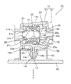
図1〜2に示すように、このチェックバルブ10は、本体部11及び蓋体部12とからなるハウジング13を有している。なお、図2〜4において、矢印Aは鉛直方向下方を示している。   As shown in FIGS. 1 and 2, the check valve 10 includes a housing 13 including a main body portion 11 and a lid body portion 12. 2 to 4, the arrow A indicates the lower side in the vertical direction.

本体部11は、複合弁体20を収容する円筒部11aと、この円筒部11aの内部に連通し、後述する燃料タンク内周に沿って配設される蒸気導入管が接続される接続管部11bとを有している。本体部11内の前記接続管部11bに連通する部分が第1ポート11dをなし、その開口部周縁には、前記複合弁体20が当接する弁座11cが形成されている。   The main body part 11 is connected to a cylindrical part 11a that accommodates the composite valve body 20 and a steam introduction pipe that communicates with the inside of the cylindrical part 11a and is disposed along the inner periphery of the fuel tank described later. 11b. A portion communicating with the connecting pipe portion 11b in the main body portion 11 forms a first port 11d, and a valve seat 11c with which the composite valve body 20 abuts is formed at the periphery of the opening portion.

また、円筒部11aの外周には、燃料タンク内壁に形成されるブラケットに固定するためのフック14が設けられており、フック14は、円筒部11aの周壁から突設された支柱14aと、支柱14aの先端から錨型に円筒部11a方向に延出された係止片14bとで構成されている。このフック14が、本発明における被取付け部への取付け手段を構成している。また、フック14の係止片14bの先端方向に位置して、円筒部11aの外周には、リブ状のブラケットへの当り部15a、15bが形成されている。   In addition, a hook 14 for fixing to a bracket formed on the inner wall of the fuel tank is provided on the outer periphery of the cylindrical portion 11a. The hook 14 includes a support column 14a protruding from the peripheral wall of the cylindrical portion 11a, and a support column. It is comprised with the latching piece 14b extended in the cylindrical part 11a direction from the front-end | tip of 14a to the bowl shape. This hook 14 constitutes an attachment means to the attached portion in the present invention. Further, contact portions 15a and 15b to rib-shaped brackets are formed on the outer periphery of the cylindrical portion 11a, which is located in the distal direction of the locking piece 14b of the hook 14.

一方、蓋体部12は、上記本体部11の円筒部11aの開口部を閉塞するように組み付けられるフランジ部12aと、このフランジ部12aの組付け面に形成された円筒部12fと、燃料タンクから引き出されて、図示しないキャニスターに接続される配管が接続される接続管部12bとを有している。この接続管部12bに連通する部分が第2ポート12iをなしている。そして、円筒部12fを本体部11の円筒部11a内周に挿入し、フランジ部12aを本体部11の端面に当接させて、その状態で溶着することにより、蓋体部12は本体部11に固着されるようになっている。   On the other hand, the lid 12 includes a flange portion 12a that is assembled so as to close the opening of the cylindrical portion 11a of the main body portion 11, a cylindrical portion 12f that is formed on the assembly surface of the flange portion 12a, and a fuel tank. And a connecting pipe portion 12b to which a pipe connected to a canister (not shown) is connected. A portion communicating with the connection pipe portion 12b forms a second port 12i. Then, the cylindrical portion 12f is inserted into the inner periphery of the cylindrical portion 11a of the main body portion 11, the flange portion 12a is brought into contact with the end surface of the main body portion 11, and the lid body portion 12 is welded in this state. It is supposed to be fixed to.

また、蓋体部12の内面には、後述する第1圧縮コイルバネ24の一端が当接する第1バネ座12eが形成されている。この第1バネ座12eは、上記円筒部12fの内周に所定間隔で突設された複数のリブ12cにより囲まれて形成されている。各リブ12cは、円筒部12fの内周から半径方向内方に伸び、その上面が次第に低くなるテーパ状をなしている。また、各リブ12cの半径方向の長さが変化していて、第1バネ座12eの第1圧縮コイルバネ24の一端が嵌合して着座する部分が、前記本体部11のフック14の延出方向とは反対方向に偏心するように形成されている。   Further, a first spring seat 12e is formed on the inner surface of the lid portion 12 so that one end of a first compression coil spring 24, which will be described later, comes into contact therewith. The first spring seat 12e is formed so as to be surrounded by a plurality of ribs 12c protruding at predetermined intervals on the inner periphery of the cylindrical portion 12f. Each rib 12c extends inward in the radial direction from the inner periphery of the cylindrical portion 12f, and has a tapered shape whose upper surface gradually decreases. Further, the length of each rib 12c in the radial direction is changed, and the portion where the first compression coil spring 24 of the first spring seat 12e is fitted and seated is the extension of the hook 14 of the main body portion 11. It is formed so as to be eccentric in the direction opposite to the direction.

更に、蓋体部12の接続管部12bの基部には、フランジ12gが形成されており、このフランジ12gに所定方向の切欠き部12hが形成されている。この切欠き12hは、後述する治具60にチェックバルブ10を保持させる際に、治具60に対してチェックバルブ10が所定の方向で保持されるようにする位置決め手段をなしている。   Further, a flange 12g is formed at the base of the connecting pipe portion 12b of the lid body portion 12, and a notch portion 12h in a predetermined direction is formed in the flange 12g. This notch 12h serves as a positioning means for holding the check valve 10 in a predetermined direction with respect to the jig 60 when the jig 60 described later holds the check valve 10.

一方、複合弁体20は、外側弁体21と、内側弁体22と、これらの弁体21、22の間に介在し、外側弁体21の内周に螺着された中間筒体23とで構成されている。   On the other hand, the composite valve body 20 includes an outer valve body 21, an inner valve body 22, an intermediate cylinder body 23 interposed between these valve bodies 21 and 22 and screwed to the inner periphery of the outer valve body 21. It consists of

外側弁体21は、円筒部11aの内周に遊嵌して、円筒部11a内でスライド可能に配置されている。そして、一方の端部に曲面状のシール面21aを有しており、このシール面21aの中央部は開口21bをなしている。シール面21aは、円筒部11aの弁座11cに当接して、前記接続管部11bに連通する第1ポート11dを開閉するようになっている。   The outer valve body 21 is loosely fitted to the inner periphery of the cylindrical portion 11a and is slidably disposed within the cylindrical portion 11a. One end portion has a curved sealing surface 21a, and the central portion of the sealing surface 21a forms an opening 21b. The seal surface 21a is in contact with the valve seat 11c of the cylindrical portion 11a to open and close the first port 11d communicating with the connection pipe portion 11b.

外側弁体21の他方の端部は開口されていて、この開口部に前記中間筒体23が取付けられている。すなわち、中間筒体23は、全体として円筒状をなし、その一方の端部外周は、上記外側弁体21の内周に挿入され、他端にはフランジ部23aが形成されていて、このフランジ部23aが外側弁体21の開口端部に当接して溶着シールされている。なお、溶着シールに先だって、内側弁体22は、中間筒体23の内部に予め挿入されている。   The other end of the outer valve body 21 is opened, and the intermediate cylinder 23 is attached to the opening. That is, the intermediate cylinder 23 has a cylindrical shape as a whole, one end outer periphery thereof is inserted into the inner periphery of the outer valve body 21, and the other end is formed with a flange portion 23a. The portion 23a contacts the opening end of the outer valve body 21 and is welded and sealed. Prior to the welding seal, the inner valve body 22 is inserted in advance into the intermediate cylinder body 23.

中間筒体23は、内側弁体22が当接する弁座23bを有している。また、フランジ23aの後端面と、蓋体部12との間には、第1圧縮コイルバネ24が介装されている。第1圧縮コイルバネ24の一端は、前述した蓋体部12の第1バネ座12eに嵌合し、ハウジング13の中心軸線に対して偏心して配置されている。第1圧縮コイルバネ24の他端は、複合弁体20のフランジ部23aの後端面に設けた第2バネ座23cに当接している。第1圧縮コイルバネ24は、複合弁体20全体を第1ポート11d方向にバネ付勢し、前記蒸気導入管41、42からの蒸気圧が一定値を超えるまでは、複合弁体20の前記シール面21aを弁座11cに当接させる。   The intermediate cylinder 23 has a valve seat 23b with which the inner valve body 22 abuts. A first compression coil spring 24 is interposed between the rear end surface of the flange 23 a and the lid body portion 12. One end of the first compression coil spring 24 is fitted into the first spring seat 12 e of the lid body 12 described above and is arranged eccentrically with respect to the central axis of the housing 13. The other end of the first compression coil spring 24 is in contact with a second spring seat 23 c provided on the rear end surface of the flange portion 23 a of the composite valve body 20. The first compression coil spring 24 biases the entire composite valve body 20 in the direction of the first port 11d, and the seal of the composite valve body 20 until the vapor pressure from the steam introduction pipes 41 and 42 exceeds a certain value. The surface 21a is brought into contact with the valve seat 11c.

なお、第1圧縮コイルバネ24は、その両端面が互いに平行で、軸線が両端面に対して直立するように形成されており、上記のように第1バネ座12e及び第2バネ座23cによって支持されて、前記両端面の中心がオフセット状態に組付けられている。   The first compression coil spring 24 is formed so that both end faces thereof are parallel to each other and the axis is upright with respect to both end faces, and is supported by the first spring seat 12e and the second spring seat 23c as described above. Thus, the center of the both end faces is assembled in an offset state.

内側弁体22は、端面が閉塞された半球状のシール面22aを有し、シール面22aに対向する端部は椀状に開口していて、この開口縁内周に設けた拡径段部22bと、外側弁体21の内周に設けたバネ受け部21cの間に、第2圧縮コイルバネ25が介装されている。第2圧縮コイルバネ25は、内側弁体22を弁座23bに当接させる方向にバネ付勢する。   The inner valve body 22 has a hemispherical sealing surface 22a whose end surface is closed, and an end portion facing the sealing surface 22a is opened in a bowl shape, and a diameter-enlarging step portion provided on the inner periphery of the opening edge. A second compression coil spring 25 is interposed between 22 b and a spring receiving portion 21 c provided on the inner periphery of the outer valve body 21. The second compression coil spring 25 biases the inner valve body 22 in a direction in which the inner valve body 22 comes into contact with the valve seat 23b.

次に、このチェックバルブ10に蒸気導入管41及びキャニスターに連結される配管45を接続して、配管ユニットを形成する方法について説明する。   Next, a method of forming a piping unit by connecting the steam introduction pipe 41 and the pipe 45 connected to the canister to the check valve 10 will be described.

図5に示すように、この配管ユニット46を形成する際には、チェックバルブ10を治具60に保持させる。治具60は、その上面にチェックバルブ10が適合する凹溝61を有し、この凹溝61には、フック14が挿入される孔部62、フランジ12gが挿入される拡径溝63が形成されている。拡径溝63には、フランジ12gに形成された切欠き部12hに適合する部分があり、チェックバルブ10を所定の方向に挿入しないと保持できないようになっている。   As shown in FIG. 5, when forming the piping unit 46, the check valve 10 is held by the jig 60. The jig 60 has a concave groove 61 in which the check valve 10 fits on the upper surface, and a hole 62 into which the hook 14 is inserted and a diameter-expanded groove 63 into which the flange 12g is inserted are formed in the concave groove 61. Has been. The diameter-enlarging groove 63 has a portion that fits into the notch 12h formed in the flange 12g, and cannot be held unless the check valve 10 is inserted in a predetermined direction.

こうして、チェックバルブ10を治具60に保持させた状態で、チェックバルブ10の一方の接続管部12bに燃料タンク内に連結される蒸気配管41を接続し、他方の接続管部11bにキャニスターに連結される配管45を接続する。この実施形態の場合、蒸気配管41及び配管45は、ポリアミド等の耐熱性の樹脂チューブで形成され、適用されるタンク形状に適合するような形状に予め曲げ加工されている。このため、チェックバルブ10に蒸気配管41及び配管45を接続して配管ユニット46を形成した状態で、燃料タンクに取付けられた状態での上下方向が定められることになる。   In this way, with the check valve 10 held by the jig 60, the steam pipe 41 connected to the fuel tank is connected to one connecting pipe portion 12b of the check valve 10, and the canister is connected to the other connecting pipe portion 11b. A pipe 45 to be connected is connected. In the case of this embodiment, the steam pipe 41 and the pipe 45 are formed of heat-resistant resin tubes such as polyamide and are previously bent into a shape that matches the applied tank shape. For this reason, in the state which connected the steam piping 41 and the piping 45 to the check valve 10, and formed the piping unit 46, the up-down direction in the state attached to the fuel tank is determined.

そして、本発明では、チェックバルブ10に設けたフランジ12gの切欠き部12hによって、治具60にチェックバルブ10を所定の方向に挿入しないと保持できないようになっているので、チェックバルブ10に対する蒸気配管41及び配管45の取付け角度が定められ、配管ユニット46の下方にフック14が位置するようにされている。   In the present invention, the notch 12h of the flange 12g provided on the check valve 10 prevents the check valve 10 from being held in the jig 60 unless the check valve 10 is inserted in a predetermined direction. The attachment angle of the pipe 41 and the pipe 45 is determined, and the hook 14 is positioned below the pipe unit 46.

図6、7に示すように、この配管ユニット46は、燃料タンク50の上面に設置されるようになっている。この実施形態の場合、燃料タンク50には、蓋体51が装着される開口部52が2つ設けられており、車体57や周辺装置に干渉しないような凹凸形状をなす上面を有している。そして、配管ユニット46は、開口部52を避けて上面の凹凸形状に適合するように予め曲げ加工されており、いくつかのブラケット53を介して、燃料タンク50及び車体57に固定されている。なお、蒸気配管41は、その端部にコネクタ47を有しており、このコネクタ47を介して、燃料タンク50内に導入された配管54に連結される。   As shown in FIGS. 6 and 7, the piping unit 46 is installed on the upper surface of the fuel tank 50. In the case of this embodiment, the fuel tank 50 is provided with two openings 52 to which the lid body 51 is attached, and has an upper surface having an uneven shape so as not to interfere with the vehicle body 57 and peripheral devices. . The piping unit 46 is bent in advance so as to conform to the uneven shape of the upper surface while avoiding the opening 52, and is fixed to the fuel tank 50 and the vehicle body 57 via some brackets 53. The steam pipe 41 has a connector 47 at its end, and is connected to the pipe 54 introduced into the fuel tank 50 via the connector 47.

この場合、チェックバルブ10のフック14は、その下方に配置されたブラケット53の取付け孔55に挿入されて係止されている。このとき、チェックバルブ10の当り部15a、15bがブラケット53の上面に当接して、チェックバルブ10をガタ付きなく保持するようになっている。   In this case, the hook 14 of the check valve 10 is inserted and locked in the mounting hole 55 of the bracket 53 disposed below the check valve 10. At this time, the contact portions 15a and 15b of the check valve 10 are brought into contact with the upper surface of the bracket 53 to hold the check valve 10 without rattling.

こうして、配管ユニット46を燃料タンク50に取付けた状態で、チェックバルブ10の第1圧縮コイルバネ24の一端が嵌合する第1バネ座12eは、ハウジング13の中心軸線Lに対して上方に偏心している。このため、第1圧縮コイルバネ24の後端部は、ハウジング13の中心軸線Lに対して上方に偏って支持され、その結果、複合弁体20に作用する第1圧縮コイルバネ24による開閉付勢力の軸線Mが、ハウジング13の中心軸線(言い換えると弁座11cの軸線)Lに対して、鉛直方向下方に傾いている。   Thus, with the piping unit 46 attached to the fuel tank 50, the first spring seat 12 e to which one end of the first compression coil spring 24 of the check valve 10 is fitted is eccentric upward with respect to the central axis L of the housing 13. Yes. Therefore, the rear end portion of the first compression coil spring 24 is supported by being biased upward with respect to the central axis L of the housing 13, and as a result, the opening / closing urging force of the first compression coil spring 24 acting on the composite valve body 20 is supported. The axis M is inclined downward in the vertical direction with respect to the center axis L of the housing 13 (in other words, the axis of the valve seat 11c).

その結果、図3,4に示すように、複合弁体20は、第1圧縮コイルバネ24による開閉付勢力の傾きによってやや傾いた状態で配置され、その両端部外周がハウジング13の内周に片当りした状態となる。なお、図3,4は、この状態をわかりやすく誇張して記載しているが、実際にはこれほど大きく傾いているわけではない。上記第1圧縮コイルバネ24による開閉付勢力の軸線Mの、ハウジング13の中心軸線(言い換えると弁座11cの軸線)Lに対する傾き角度θは、15〜20°であることが好ましい。   As a result, as shown in FIGS. 3 and 4, the composite valve body 20 is arranged in a slightly inclined state due to the inclination of the opening / closing urging force by the first compression coil spring 24, and the outer periphery of both ends is separated from the inner periphery of the housing 13. It will be in a hit state. 3 and 4 show this state in an exaggerated manner in an easy-to-understand manner, but the actual inclination is not so great. The inclination angle θ of the axis M of the opening / closing urging force by the first compression coil spring 24 with respect to the center axis L of the housing 13 (in other words, the axis of the valve seat 11c) is preferably 15 to 20 °.

また、ハウジング13の中心軸線(言い換えると弁座11cの軸線)方向に見たとき、上記第1圧縮コイルバネ24による開閉付勢力の軸線Mの方向は、鉛直方向の下方から±30°、好ましくは±10°の範囲に設定されていればよく、この実施形態では、ほぼ鉛直方向下方に向いている。   When viewed in the direction of the center axis of the housing 13 (in other words, the axis of the valve seat 11c), the direction of the axis M of the opening / closing biasing force by the first compression coil spring 24 is ± 30 ° from below in the vertical direction, preferably It suffices if it is set in a range of ± 10 °, and in this embodiment, it is directed substantially downward in the vertical direction.

次に、このチェックバルブ10の作用について説明する。このチェックバルブ10においては、燃料タンク50内の蒸気圧が所定値以下のときは、図2、3に示すように、第1圧縮コイルバネ24の付勢力によって複合弁体20のシール面21aが本体部11の弁座11cに当接し、チェックバルブ10は閉じた状態となる。   Next, the operation of the check valve 10 will be described. In this check valve 10, when the vapor pressure in the fuel tank 50 is not more than a predetermined value, the sealing surface 21 a of the composite valve body 20 is moved to the main body by the urging force of the first compression coil spring 24 as shown in FIGS. The check valve 10 comes into contact with the valve seat 11c of the portion 11 and is closed.

また、燃料タンク50内の蒸気圧が所定値以上になると、図4に示すように、第1圧縮コイルバネ24の付勢力に抗して、複合弁体20が本体部11の弁座11cから離れ、蒸気導入管41を通して、燃料タンク50内の燃料蒸気が導入され、チェックバルブ10及び配管45を通って、図示しないキャニスターに送られる。   When the vapor pressure in the fuel tank 50 exceeds a predetermined value, the composite valve body 20 separates from the valve seat 11c of the main body 11 against the urging force of the first compression coil spring 24 as shown in FIG. The fuel vapor in the fuel tank 50 is introduced through the steam introduction pipe 41 and is sent to the canister (not shown) through the check valve 10 and the pipe 45.

更に、燃料タンク50内の圧力が所定値以下の負圧となったときには、キャニスターに接続された配管45側の方が高い圧力となるため、複合弁体20内の第2圧縮コイルバネ25に抗して、内側弁体22のシール面22aが弁座23bから離れて内部に押込められ、配管45側の気体が複合弁体20内を通って燃料タンク50内に導入される。   Further, when the pressure in the fuel tank 50 becomes a negative pressure equal to or less than a predetermined value, the pressure on the side of the pipe 45 connected to the canister is higher, so that the second compression coil spring 25 in the composite valve body 20 is resisted. Then, the sealing surface 22a of the inner valve body 22 is pushed away from the valve seat 23b and the gas on the pipe 45 side is introduced into the fuel tank 50 through the composite valve body 20.

こうして、燃料タンク50内の圧力を常時一定の範囲に保って、燃料タンク50の破裂や変形、給油口からの燃料の吹き出し等を防ぐようにしている。   In this way, the pressure in the fuel tank 50 is always kept within a certain range to prevent the fuel tank 50 from bursting or deforming, blowing out fuel from the fuel filler port, and the like.

ところで、前述したように、例えば自動車が山道を登り、頂上の目的地に到着してエンジンを停止したときような場合には、燃料タンク内の温度は更にしばらく上昇を続けた後、ある程度時間が経過してから徐々に温度が低下していく。このため、車両が停止した後も、燃料タンク内の圧力が高く、チェックバルブ10が図4に示すような半開き状態になって、燃料蒸気をキャニスターに逃がす状態がしばらく続くことがある。そのようなときに、従来のチェックバルブでは、燃料蒸気の通過に伴って、半開き状態にある複合弁体20がハウジング13内で踊って振動し、ハウジング13内壁に衝突して打音を発生し、運転者等に不安をいだかせることがあった。   By the way, as described above, for example, when a car climbs a mountain road, arrives at the summit destination and stops the engine, the temperature in the fuel tank continues to rise for a while, and after a certain period of time, The temperature gradually decreases after the lapse. For this reason, even after the vehicle stops, the pressure in the fuel tank is high, the check valve 10 may be in a half-open state as shown in FIG. 4, and the state where fuel vapor is allowed to escape to the canister may continue for a while. In such a case, in the conventional check valve, as the fuel vapor passes, the composite valve body 20 in the half-open state dances and vibrates in the housing 13 and collides with the inner wall of the housing 13 to generate a hitting sound. , Drivers sometimes worried.

しかし、このチェックバルブ10においては、前述したように、複合弁体20に作用する第1圧縮コイルバネ24による開閉付勢力の軸線Mが、ハウジング13の中心軸線(言い換えると弁座11cの軸線)Lに対して鉛直方向下方に傾いており、複合弁体20自身の重力もそれと同じ方向に作用するため、複合弁体20の両端部外周が、図3,4に示すように、ハウジング13の内周に片当りした状態となる。そのため、複合弁体20がハウジング13内で踊って振動することが効果的に防止され、打音が発生することをほぼ確実に防止することができる。   However, in the check valve 10, as described above, the axis M of the opening / closing biasing force by the first compression coil spring 24 acting on the composite valve body 20 is the center axis of the housing 13 (in other words, the axis of the valve seat 11c) L. The gravity of the composite valve body 20 itself acts in the same direction as that, so that the outer periphery of both ends of the composite valve body 20 is inside the housing 13 as shown in FIGS. It will be in a state where it hits one side of the circumference. Therefore, it is possible to effectively prevent the composite valve body 20 from dancing and vibrating in the housing 13 and almost certainly prevent the hitting sound from being generated.

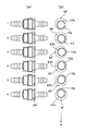
図8〜10には、上記チェックバルブ10を用いた打音発生試験の方法及び結果が示されている。   FIGS. 8 to 10 show a method and result of a hitting sound generation test using the check valve 10.

図8において、(a)は試験に供したチェックバルブ10の側面図であり、(b)は試験に供したチェックバルブ10の軸線方向から見たときの、第1圧縮コイルバネ24の第1バネ座12e(太線)及び第2バネ座23c(細線)の位置関係を示している。矢印Aは鉛直方向下方を示している。なお、第1圧縮コイルバネ24としては、その両端面が互いに平行で、軸線が両端面に対して直立するように形成され、第1バネ座12e及び第2バネ座23cによって支持されて、前記両端面の中心がオフセット状態に組付けられているものを使用した。   8A is a side view of the check valve 10 subjected to the test, and FIG. 8B is a first spring of the first compression coil spring 24 when viewed from the axial direction of the check valve 10 subjected to the test. The positional relationship between the seat 12e (thick line) and the second spring seat 23c (thin line) is shown. An arrow A indicates a vertically downward direction. The first compression coil spring 24 is formed so that both end faces thereof are parallel to each other and the axis is upright with respect to both end faces, and is supported by the first spring seat 12e and the second spring seat 23c, and the both ends The center of the surface was assembled in an offset state.

また、同図(b)における点M’は、第1圧縮コイルバネ24による開閉付勢力の軸線Mの傾き方向を示している。そして、1〜6の試験条件は、同一試験品を軸方向を中心として回転させて試験台に固定することにより、上記第1圧縮コイルバネ24による開閉付勢力の軸線Mの傾き方向を変えている。試験条件1は、上記軸線Mが鉛直方向上方に傾いており、試験条件2は、上記軸線Mが上記軸線Mが鉛直方向上方から45°傾いており、試験条件3は、上記軸線Mが水平方向に傾いており、試験条件4は、上記軸線Mが鉛直方向下方から45°傾いており、試験条件5は、上記軸線Mが鉛直方向下方から30°傾いており、試験条件6は、上記軸線Mが鉛直方向下方に向いている。本発明の実施例となるのは、上記試験条件5,6の取付け状態である。なお、矢印Aは鉛直方向下方を示している。   Further, a point M ′ in FIG. 7B indicates the inclination direction of the axis M of the opening / closing urging force by the first compression coil spring 24. And the test conditions of 1-6 change the inclination direction of the axis M of the opening-and-closing biasing force by the said 1st compression coil spring 24 by rotating the same test article centering on an axial direction, and fixing to a test stand. . Test condition 1 is that the axis M is tilted upward in the vertical direction, test condition 2 is that the axis M is tilted 45 ° from above in the vertical direction, and test condition 3 is that the axis M is horizontal. In test condition 4, the axis M is inclined 45 ° from below in the vertical direction. In test condition 5, the axis M is inclined 30 ° from below in the vertical direction. The axis M is directed downward in the vertical direction. The embodiment of the present invention is the mounting state of the test conditions 5 and 6 described above. In addition, the arrow A has shown the perpendicular direction downward direction.

すなわち、上記各チェックバルブ10の第1ポート11dに、空気圧を0→10KPaとなるように徐々に増大してかけた後、10→3KPaとなるように徐々に減圧させて、チェックバルブ10を通過する空気の流量を流量計(50L/min計)で測定すると共に、そのときの音圧をチェックバルブ10から540mm離れた位置に配置した騒音計(小野測器製、商品名「LA1245」)によって測定した。複合弁体20が開いて、流れる空気量が増大するに伴って音圧は徐々に高まるが、複合弁体20がハウジング13内で振動して異音(打音)が発生するときには、上記音圧は急激に増大する。したがって、音圧の変化を調べることにより、異音の発生の有無をより正確に調べることができる。   That is, the air pressure is gradually increased from 0 to 10 KPa to the first port 11 d of each check valve 10, and then gradually reduced from 10 to 3 KPa to pass through the check valve 10. The flow rate of the air to be measured is measured with a flow meter (50 L / min meter), and the sound pressure at that time is measured by a noise meter (trade name “LA1245”, manufactured by Ono Sokki Co., Ltd.) located 540 mm away from the check valve 10. It was measured. The sound pressure gradually increases as the composite valve body 20 opens and the amount of flowing air increases. However, when the composite valve body 20 vibrates in the housing 13 and an abnormal sound (sounding sound) is generated, the above sound is generated. The pressure increases rapidly. Therefore, by examining the change in sound pressure, it is possible to more accurately investigate the presence or absence of abnormal noise.

図9は、上記試験結果を示している。同図(a)は、上記試験条件1〜6について、それぞれ20個ずつの試料を用いて試験した結果を示し、加圧NGとは加圧時に異音が発生したこと、減圧NGとは減圧時に異音が発生したことを示し、加圧OKとは加圧時に異音が発生しなかったこと、減圧OKとは減圧時に異音が発生しなかったことを示す。   FIG. 9 shows the test results. FIG. 6A shows the results of testing using 20 samples for each of the above test conditions 1 to 6. The pressure NG indicates that abnormal noise was generated during pressurization, and the pressure reduction NG indicates pressure reduction. Occasionally, abnormal noise was generated. Pressurized OK indicates that no abnormal noise was generated during pressurization, and reduced pressure OK indicates that no abnormal noise was generated during depressurization.

このように、本発明の実施例となる試験条件5,6は、異音の発生が顕著に抑制されており、特に試験条件6は、加圧時における異音の発生がほとんどないことがわかる。   Thus, it can be seen that test conditions 5 and 6 which are examples of the present invention significantly suppress the generation of abnormal noise, and particularly test condition 6 shows that there is almost no abnormal noise during pressurization. .

また、軸線Mが鉛直方向下方から45°以上傾いている試験条件1〜4においては、加圧時又は減圧時のいずれか、又は両方で異音が発生しており、軸線Mを傾かせたものであっても、異音発生抑制効果が十分に得られていないことがわかる。特に、軸線Mが鉛直方向上方から±45°の範囲にある試験品1,2では、異音発生抑制効果がほとんど得られないことがわかる。その理由は、第1圧縮コイルバネ24による開閉付勢力の軸線Mを傾かせてあっても、その傾き方向が上方に向いている場合には、複合弁体20の重力が、軸線Mの傾きによる偏心した付勢力を、ハウジング13の軸線Lに近い方向に是正してしまうためと考えられる。   In addition, in test conditions 1 to 4 in which the axis M is inclined at 45 ° or more from below in the vertical direction, abnormal noise is generated either during pressurization or during decompression, or both, and the axis M is tilted. Even if it is a thing, it turns out that the noise generation suppression effect is not fully acquired. In particular, it can be seen that in the test products 1 and 2 in which the axis M is in the range of ± 45 ° from the upper side in the vertical direction, the effect of suppressing abnormal noise generation is hardly obtained. The reason is that even if the axis M of the opening / closing urging force by the first compression coil spring 24 is tilted, if the tilt direction is directed upward, the gravity of the composite valve body 20 is due to the tilt of the axis M. It is considered that the eccentric biasing force is corrected in a direction close to the axis L of the housing 13.

また、同図(b)は、第1圧縮コイルバネ24の第1バネ座12eの中心が、第2バネ座23cの中心に対して偏心しておらず、ハウジング13の軸心に配置された試料を作成し、この試料について、第1バネ座12eを、第2バネ座23cに対して、軸方向を中心として回転させて試験台に固定し、上記と同様な異音発声抑制効果についての試験を行った結果を示している。この結果から、第1バネ座12eの中心が、第2バネ座23cの中心に対して偏心していない場合には、いずれの試料も加圧時及び減圧時でNGとなり、異音発生を抑制できないことが分かる。   Further, FIG. 4B shows a sample arranged at the axis of the housing 13 in which the center of the first spring seat 12e of the first compression coil spring 24 is not eccentric with respect to the center of the second spring seat 23c. For this sample, the first spring seat 12e is rotated around the axial direction with respect to the second spring seat 23c and fixed to the test table, and the same test for the effect of suppressing abnormal sound production is performed. The results are shown. From this result, when the center of the first spring seat 12e is not eccentric with respect to the center of the second spring seat 23c, any sample becomes NG at the time of pressurization and decompression, and the generation of abnormal noise cannot be suppressed. I understand that.

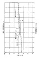
図10は、図9(a)の試料No.1について、試験条件1,3,6の測定結果を示しており、横軸は空気流量(単位L/min)、縦軸は音圧(db)を表している。エアを流す前での暗騒音は約50dbで、空気の流量が増大するにつれて、音圧は徐々に上昇していき、流量50L/minでは約60dbとなる。このとき、試験条件1においては、途中で急激に音圧が上昇し、異音が発生する。また、試験条件3においては、試験条件1よりも遅れて音圧が急激に上昇し、やはり異音が発生する。これに対して、試験条件6では、音圧が急激に上昇するところはなく、異音はほぼ確実に抑制されることがわかる。   10 shows the sample No. of FIG. 1 shows the measurement results of test conditions 1, 3, and 6. The horizontal axis represents the air flow rate (unit: L / min), and the vertical axis represents the sound pressure (db). The background noise before flowing air is about 50 db, and as the air flow rate increases, the sound pressure gradually increases and becomes about 60 db at a flow rate of 50 L / min. At this time, in the test condition 1, the sound pressure suddenly increases in the middle and abnormal noise is generated. Moreover, in the test condition 3, the sound pressure increases rapidly after the test condition 1, and an abnormal noise is generated. On the other hand, in test condition 6, there is no place where the sound pressure increases rapidly, and it can be seen that abnormal noise is almost certainly suppressed.

図11〜13には、本発明による圧力開閉弁を自動車の燃料タンクの蒸気配管(ベーパーライン)に設けるチェックバルブに適用した他の実施形態が示されている。なお、図中矢印Aは鉛直方向下方を示している。   FIGS. 11 to 13 show another embodiment in which the pressure on-off valve according to the present invention is applied to a check valve provided in a steam pipe (vapor line) of a fuel tank of an automobile. In addition, the arrow A in the figure shows the downward direction in the vertical direction.

図11に示すように、この実施形態によるチェックバルブ10aは、ハウジング13の本体部11に、分岐した2つの接続管部11e、11fが設けられており、蓋体部12の第1バネ座12eが、フック14と同じ方向に偏心して形成されている点が、上記実施形態と異なっている。   As shown in FIG. 11, in the check valve 10 a according to this embodiment, the main body portion 11 of the housing 13 is provided with two branched connection pipe portions 11 e and 11 f, and the first spring seat 12 e of the lid portion 12. However, it is different from the above embodiment in that it is formed eccentrically in the same direction as the hook 14.

図12に示すように、チェックバルブ10aの接続管部11b、11cには、蒸気導入管41、42が接続され、この蒸気導入管41、42の先端にはカットバルブ43、44が接続される。また、上記チェックバルブ10の接続管部12bには、図示しないキャニスターに連結される配管45が接続される。そして、この配管ユニット46aは、燃料タンク50内の天井壁に固定されるようになっている。   As shown in FIG. 12, steam inlet pipes 41 and 42 are connected to the connecting pipe portions 11b and 11c of the check valve 10a, and cut valves 43 and 44 are connected to the tips of the steam inlet pipes 41 and 42, respectively. . Further, a pipe 45 connected to a canister (not shown) is connected to the connecting pipe portion 12b of the check valve 10. The piping unit 46 a is fixed to the ceiling wall in the fuel tank 50.

すなわち、図13に示すように、燃料タンク50の天井壁の内面に固着されたブラケット53の取付け孔55に、チェックバルブ10aのフック14を挿入して係止することにより、チェックバルブ10aは燃料タンク50の天井壁内面に固定される。この状態で、第1圧縮コイルバネ24の一端を支持する第1バネ座12eは上方に偏って配置されている。   That is, as shown in FIG. 13, by inserting the hook 14 of the check valve 10a into the mounting hole 55 of the bracket 53 fixed to the inner surface of the ceiling wall of the fuel tank 50 and locking the check valve 10a, It is fixed to the inner surface of the ceiling wall of the tank 50. In this state, the first spring seat 12e that supports one end of the first compression coil spring 24 is disposed to be biased upward.

したがって、この実施形態においても、複合弁体20に作用する第1圧縮コイルバネ24による開閉付勢力の軸線Mが、ハウジング13の中心軸線(言い換えると弁座11cの軸線)Lに対して鉛直方向下方に傾いており、複合弁体20自身の重力もそれと同じ方向に作用するため、複合弁体20の両端部外周がハウジング13の内周に片当りした状態となり、複合弁体20がハウジング13内で踊って振動することが効果的に防止され、打音が発生することをほぼ確実に防止することができる。   Therefore, also in this embodiment, the axis M of the opening / closing biasing force by the first compression coil spring 24 acting on the composite valve body 20 is vertically downward with respect to the central axis L of the housing 13 (in other words, the axis of the valve seat 11c). Since the gravity of the composite valve body 20 itself acts in the same direction, the outer periphery of both ends of the composite valve body 20 comes into contact with the inner periphery of the housing 13, and the composite valve body 20 is in the housing 13. It is effectively prevented from dancing and vibrating, and it is possible to almost certainly prevent the hitting sound from being generated.

本発明は、例えば燃料タンク用チェックバルブ等に好適な圧力開閉弁であって、作動時に弁体が振動して発生する打音を低減できる圧力開閉弁として利用することができる。   The present invention is a pressure on-off valve suitable for, for example, a fuel tank check valve and the like, and can be used as a pressure on-off valve that can reduce a striking sound generated when the valve body vibrates during operation.

本発明の圧力開閉弁を燃料タンク用チェックバルブに適用した一実施形態を示す分解斜視図である。It is a disassembled perspective view which shows one Embodiment which applied the pressure on-off valve of this invention to the check valve for fuel tanks. 同チェックバルブの弁が閉じた状態の断面図である。It is sectional drawing of the state which the valve of the check valve closed. 同チェックバルブの取付け状態における弁が閉じた状態の断面図である。It is sectional drawing of the state in which the valve in the attachment state of the check valve was closed. 同チェックバルブの取付け状態における弁が開いた状態の断面図である。It is sectional drawing of the state in which the valve in the attachment state of the check valve was opened. 同チェックバルブに蒸気導入管及びキャニスターに連結される配管を接続して配管ユニットを形成する方法を示す説明図である。It is explanatory drawing which shows the method of connecting the piping connected with a steam inlet pipe and a canister to the check valve, and forming a piping unit. 同配管ユニットを燃料タンクに取付けた状態を示す断面図である。It is sectional drawing which shows the state which attached the piping unit to the fuel tank. 同配管ユニットを燃料タンクに取付けた状態を示す平面図である。It is a top view which shows the state which attached the same piping unit to the fuel tank. チェックバルブを用いた打音発生試験の方法を示す説明図である。It is explanatory drawing which shows the method of a sound generation test using a check valve. 同試験結果を示す説明図である。It is explanatory drawing which shows the test result. 同試験において空気の流量と音圧との関係を測定した結果を示す図表である。It is a graph which shows the result of having measured the relationship between the air flow rate and the sound pressure in the same test. 本発明の圧力開閉弁を燃料タンク用チェックバルブに適用した他の実施形態を示す分解斜視図である。It is a disassembled perspective view which shows other embodiment which applied the pressure on-off valve of this invention to the check valve for fuel tanks. 同チェックバルブを燃料タンク内に配設する状態を示す斜視図である。It is a perspective view which shows the state which arrange | positions the same check valve in a fuel tank. 同チェックバルブを燃料タンクの天井壁内面に取付けた状態を示す断面図である。It is sectional drawing which shows the state which attached the same check valve to the ceiling wall inner surface of a fuel tank.

符号の説明Explanation of symbols

10,10a チェックバルブ
11 本体部
11d 第1ポート
11a 円筒部
11c 弁座
11b、11e、11f 接続管部
12 蓋体部
12a フランジ部
12b 接続管部
12c リブ
12e 第1バネ座
12f 円筒部
12g フランジ
12h 切欠き部
12i 第2ポート
13 ハウジング
14 フック
14b 係止片
14a 支柱
15a、15b 当り部
20 複合弁体
21 外側弁体
21a シール面
21c バネ受け部
21b 開口
22 内側弁体
22b 拡径段部
23c 第2バネ座
23 中間筒体
23a フランジ部
23b 弁座
24 第1圧縮コイルバネ
25 第2圧縮コイルバネ
41、42 蒸気導入管
43、44 カットバルブ
45 キャニスターに連通する配管
46、46a 配管ユニット
47 コネクタ
50 燃料タンク
51 蓋体
52 開口部
53 ブラケット
54 配管
55 孔
60 治具
61 凹溝
62 孔部
63 拡径溝
L ハウジングの中心軸線(言い換えると弁座の軸線)
M 第1圧縮コイルバネによる開閉付勢力の軸線
A 鉛直方向下方
10, 10a Check valve 11 Body portion 11d First port 11a Cylindrical portion 11c Valve seats 11b, 11e, 11f Connection pipe portion 12 Cover body portion 12a Flange portion 12b Connection pipe portion 12c Rib 12e First spring seat 12f Cylindrical portion 12g Flange 12h Notch portion 12i Second port 13 Housing 14 Hook 14b Locking piece 14a Strut 15a, 15b Contact portion 20 Composite valve body 21 Outer valve body 21a Seal surface 21c Spring receiving portion 21b Opening 22 Inner valve body 22b Expanded stepped portion 23c First Two spring seats 23 Intermediate cylinder 23a Flange 23b Valve seat 24 First compression coil spring 25 Second compression coil springs 41, 42 Steam introduction pipes 43, 44 Cut valve 45 Piping 46, 46a Piping unit 47 Connector 50 Fuel tank 51 Lid 52 Opening 53 Bracket 54 Piping 55 Hole 60 Jig 61 Recessed groove 62 Hole 63 Expanded groove L Center axis of housing (in other words, axis of valve seat)
M Axis A of opening / closing urging force by first compression coil spring Vertically downward

Claims (3)

第1ポートと第2ポートとを備えたハウジングと、該ハウジング内に収容され、バネによって付勢されて前記第1ポートを通常は閉塞しかつ前記第1ポートと前記第2ポートとの差圧が所定値を超えると開く弁体とを有し、横向きにして設置される圧力開閉弁において、前記バネの一端が当接する前記ハウジングに設けた第1バネ座の中心に対して、前記バネの他端が当接する前記弁体に設けた第2バネ座の中心が偏位して配置されており、その偏位方向は、ハウジングの中心軸線方向に沿って見たとき、鉛直方向下方から±30°の範囲にあり、前記バネは、圧縮コイルバネからなり、その両端面が互いに平行で、軸線が両端面に対して直立するように形成されており、前記第1バネ座及び第2バネ座によって支持されて、前記両端面の中心がオフセット状態に組付けられていることを特徴とする圧力開閉弁。   A housing having a first port and a second port; and a pressure difference between the first port and the second port that is received in the housing and biased by a spring to normally close the first port; In a pressure on-off valve that has a valve body that opens when the value exceeds a predetermined value and is installed in a lateral direction, the spring has an end against the center of the first spring seat provided on the housing with which one end of the spring abuts. The center of the second spring seat provided on the valve body with which the other end abuts is deviated and the direction of the deviation is ±± from the lower side in the vertical direction when viewed along the central axis direction of the housing. The first spring seat and the second spring seat are in a range of 30 °, the spring is formed of a compression coil spring, and both end faces thereof are parallel to each other and the axis is upright with respect to both end faces. Supported by the center of both end faces Is a pressure on-off valve characterized by being assembled in an offset state. 前記ハウジングには、被取付け部に対する取付け手段が設けられ、この取付け手段は、取付け状態において前記第1バネ座の中心に対する前記第2バネ座の中心の偏位方向が前記角度範囲になるように配置されている請求項1記載の圧力開閉弁。   The housing is provided with attachment means for the attachment portion, and the attachment means is arranged so that a deviation direction of the center of the second spring seat with respect to the center of the first spring seat is in the angular range in the attached state. The pressure on-off valve according to claim 1, which is arranged. 前記ハウジングには、圧力開閉弁にチューブを接続する際に該圧力開閉弁を保持させるための治具に対する位置決め手段が設けられ、この位置決め手段は、該治具に保持された圧力開閉弁にチューブを接続して形成される配管ユニットの予定される取付け状態において、前記第1バネ座の中心に対する前記第2バネ座の中心の偏位方向が前記角度範囲になるように配置されている請求項1又は2記載の圧力開閉弁。   The housing is provided with positioning means for a jig for holding the pressure on / off valve when the tube is connected to the pressure on / off valve, and the positioning means is connected to the pressure on / off valve held by the jig. The piping unit formed by connecting the two spring seats is arranged such that the direction of deviation of the center of the second spring seat with respect to the center of the first spring seat falls within the angular range. The pressure on-off valve according to 1 or 2.
JP2005150705A 2005-05-24 2005-05-24 Pressure on / off valve Active JP4731999B2 (en)

Priority Applications (1)

Application Number Priority Date Filing Date Title
JP2005150705A JP4731999B2 (en) 2005-05-24 2005-05-24 Pressure on / off valve

Applications Claiming Priority (1)

Application Number Priority Date Filing Date Title
JP2005150705A JP4731999B2 (en) 2005-05-24 2005-05-24 Pressure on / off valve

Publications (2)

Publication Number Publication Date
JP2006329245A JP2006329245A (en) 2006-12-07
JP4731999B2 true JP4731999B2 (en) 2011-07-27

Family

ID=37551149

Family Applications (1)

Application Number Title Priority Date Filing Date
JP2005150705A Active JP4731999B2 (en) 2005-05-24 2005-05-24 Pressure on / off valve

Country Status (1)

Country Link
JP (1) JP4731999B2 (en)

Families Citing this family (3)

* Cited by examiner, † Cited by third party
Publication number Priority date Publication date Assignee Title
BRPI0616483B8 (en) * 2005-10-03 2020-05-19 Honda Motor Co Ltd pressure control device
WO2010064475A1 (en) * 2008-12-02 2010-06-10 株式会社パイオラックス Check valve
JP2015500411A (en) * 2011-10-18 2015-01-05 ライトセイル エナジー インコーポレイテッド Compressed gas energy storage system

Citations (8)

* Cited by examiner, † Cited by third party
Publication number Priority date Publication date Assignee Title
JPS63124818A (en) * 1986-11-13 1988-05-28 Yamaha Motor Co Ltd Check valve
JPH03117171U (en) * 1990-03-14 1991-12-04
JPH0861554A (en) * 1994-08-17 1996-03-08 Nabco Ltd Pressure control valve
JPH10205631A (en) * 1997-01-17 1998-08-04 Piolax Inc Check valve
JP2003148265A (en) * 2001-11-14 2003-05-21 Piolax Inc In-tank valve device
JP2004019805A (en) * 2002-06-17 2004-01-22 Advics:Kk Check valve and brake actuator using the same
JP2004068811A (en) * 2002-06-12 2004-03-04 Advics:Kk Check valve and brake actuator using the check valve
JP2005030540A (en) * 2003-07-10 2005-02-03 Piolax Inc Method of manufacturing float valve device

Family Cites Families (1)

* Cited by examiner, † Cited by third party
Publication number Priority date Publication date Assignee Title
JP2955300B2 (en) * 1989-09-29 1999-10-04 京セラ株式会社 Image processing method and apparatus

Patent Citations (8)

* Cited by examiner, † Cited by third party
Publication number Priority date Publication date Assignee Title
JPS63124818A (en) * 1986-11-13 1988-05-28 Yamaha Motor Co Ltd Check valve
JPH03117171U (en) * 1990-03-14 1991-12-04
JPH0861554A (en) * 1994-08-17 1996-03-08 Nabco Ltd Pressure control valve
JPH10205631A (en) * 1997-01-17 1998-08-04 Piolax Inc Check valve
JP2003148265A (en) * 2001-11-14 2003-05-21 Piolax Inc In-tank valve device
JP2004068811A (en) * 2002-06-12 2004-03-04 Advics:Kk Check valve and brake actuator using the check valve
JP2004019805A (en) * 2002-06-17 2004-01-22 Advics:Kk Check valve and brake actuator using the same
JP2005030540A (en) * 2003-07-10 2005-02-03 Piolax Inc Method of manufacturing float valve device

Also Published As

Publication number Publication date
JP2006329245A (en) 2006-12-07

Similar Documents

Publication Publication Date Title
US8561638B2 (en) Check valve
KR100676047B1 (en) Pressure opening and closing valve
JP4731999B2 (en) Pressure on / off valve
WO2013031273A1 (en) Check valve
JP5772350B2 (en) Valve device
JP2003240144A (en) Two-way valve
JP6200097B2 (en) Valve case mounting structure
MX2012008763A (en) Fuel cutoff valve.
US10851747B2 (en) Mounting structure of fuel device
JP2010052616A (en) Valve unit for in-tank
JP5650987B2 (en) Fuel tank
JP2006044586A (en) Check valve for fuel tank
JP4585347B2 (en) Baffle plate
JP5012664B2 (en) Fuel tank venting device
US7946624B2 (en) Mounting structures for piping members
US6779545B2 (en) Pressure control valve for fuel tank
JP2005127501A (en) Resin fuel tank mounting valve
JP6363414B2 (en) Shock absorber
EP1378692B1 (en) Valve
JP2024502905A (en) Emergency deaerator
JP2005114062A (en) Check valve
JP7115890B2 (en) valve device
JP3958304B2 (en) Inflator
JP2010173397A (en) Fuel shutoff valve
JP7076573B2 (en) Gas-liquid separator with check valve

Legal Events

Date Code Title Description
A621 Written request for application examination

Free format text: JAPANESE INTERMEDIATE CODE: A621

Effective date: 20071219

A977 Report on retrieval

Free format text: JAPANESE INTERMEDIATE CODE: A971007

Effective date: 20100728

A131 Notification of reasons for refusal

Free format text: JAPANESE INTERMEDIATE CODE: A131

Effective date: 20100921

A521 Written amendment

Free format text: JAPANESE INTERMEDIATE CODE: A523

Effective date: 20101122

A521 Written amendment

Free format text: JAPANESE INTERMEDIATE CODE: A821

Effective date: 20101122

TRDD Decision of grant or rejection written
A01 Written decision to grant a patent or to grant a registration (utility model)

Free format text: JAPANESE INTERMEDIATE CODE: A01

Effective date: 20110419

A01 Written decision to grant a patent or to grant a registration (utility model)

Free format text: JAPANESE INTERMEDIATE CODE: A01

A61 First payment of annual fees (during grant procedure)

Free format text: JAPANESE INTERMEDIATE CODE: A61

Effective date: 20110420

FPAY Renewal fee payment (event date is renewal date of database)

Free format text: PAYMENT UNTIL: 20140428

Year of fee payment: 3

R150 Certificate of patent or registration of utility model

Ref document number: 4731999

Country of ref document: JP

Free format text: JAPANESE INTERMEDIATE CODE: R150

Free format text: JAPANESE INTERMEDIATE CODE: R150

R250 Receipt of annual fees

Free format text: JAPANESE INTERMEDIATE CODE: R250

R250 Receipt of annual fees

Free format text: JAPANESE INTERMEDIATE CODE: R250

R250 Receipt of annual fees

Free format text: JAPANESE INTERMEDIATE CODE: R250

S111 Request for change of ownership or part of ownership

Free format text: JAPANESE INTERMEDIATE CODE: R313117

R350 Written notification of registration of transfer

Free format text: JAPANESE INTERMEDIATE CODE: R350

R250 Receipt of annual fees

Free format text: JAPANESE INTERMEDIATE CODE: R250