JP4092773B2 - Method and apparatus for converting the number of frames of an image signal - Google Patents
Method and apparatus for converting the number of frames of an image signal Download PDFInfo
- Publication number
- JP4092773B2 JP4092773B2 JP12012798A JP12012798A JP4092773B2 JP 4092773 B2 JP4092773 B2 JP 4092773B2 JP 12012798 A JP12012798 A JP 12012798A JP 12012798 A JP12012798 A JP 12012798A JP 4092773 B2 JP4092773 B2 JP 4092773B2
- Authority
- JP
- Japan
- Prior art keywords
- signal
- unit
- motion
- block
- frame
- Prior art date
- Legal status (The legal status is an assumption and is not a legal conclusion. Google has not performed a legal analysis and makes no representation as to the accuracy of the status listed.)
- Expired - Fee Related
Links
Images


Description
【0001】
【発明の属する技術分野】
本発明は画像信号のフレーム数変換方法および装置に係り、特に動き補正信号処理によりフレーム数を変換するに好適なフレーム数変換方法および装置に関する。
【0002】
【従来の技術】
近年、マルチメディア化の進展に伴い、テレビジョン受像機においても、各種方式のテレビジョン信号やPC画像信号等の画像フォーマットの異なる信号を表示する機能が必要となる。また、高画質化や平面ディスプレイ対応の機能として、順次走査による画像表示機能が必要になる。これらの機能を実現するには、各種入力信号を画像表示部のフォーマットに変換するため、フレーム数変換や順次走査化の信号処理が必要となる。この信号処理をコマ繰り返しやコマ落としなどの単純な方法で行うと、動き画像で滑らかさが損なわれるモーションジャダーなどの画質劣化が発生する。
【0003】
動き補正フレーム数変換処理は、この種の画質劣化を回避する技術であり、動きベクトルを用いて前後のフレームの画像位置を移動させて内挿フレームの信号を生成するものである。この動き補正フレーム数変換処理に関しては、例えば特開平7−170496号公報において、動きベクトルを効率よく探索する技術が開示されている。また特開平7−336650号公報においては、動き補正に固有な動画エッジ周縁部における解像度低下などの劣化を回避する技術が開示されている。
【0004】
【発明が解決しようとする課題】
しかしながら、これらの従来技術においては、前者については動き検出の精度に課題を有し、また後者については信号処理の複雑さに課題を有している。すなわち従来の技術では、画質を高めようとすると信号処理の回路規模が大きくなり、逆に信号処理の回路規模を小さくすると画質劣化を十分排除できなくなるというのが実情である。
【0005】
従って本発明の目的は、高画質でしかも回路規模の小さい画像信号のフレーム数変換方法および装置を提供することにある。
【0006】
【課題を解決するための手段】
上記目的は、画像信号より検出した動画ブロックに対してブロックマッチング処理でブロック単位の動きベクトルを検出し、この検出したブロック単位動きベクトルの動き補正誤差の大小に応じて現ブロックと隣接ブロックの動きベクトルより画素単位の動きベクトルを生成し、この画素単位の動きベクトルの動き補正誤差の大小に応じて画像信号の内挿フレームを生成し、この内挿フレームを用いて画像信号のフレーム数を変換する画像信号のフレーム数変換方法により、達成される。
【0007】
また本発明に係るフレーム数変換装置では、画像信号に基づいて静止ブロック又は動画ブロックを検出する動き検出部と、動画ブロックに対してブロックマッチング処理でブロック単位の動きベクトルを検出するブロック単位動きベクトル探索部と、検出したブロック単位動きベクトルの動き補正誤差の大小に応じて現ブロックと隣接ブロックの動きベクトルから画素単位の動きベクトルを生成する画素単位動きベクトル生成部と、画素単位の動きベクトルの動き補正誤差の大小に応じて上記画像信号の内挿フレームを生成する動き補正内挿フレーム生成部とを備える。ここで画像信号としては、飛び越し走査の画像信号を用いる場合と順次走査の画像信号を用いる場合があるが、基本的には両者の装置構成は同じである。しかし具体的構成には違いがあるので、これらについては後述する。
【0008】
本発明は、具体的には、次のような技術的手段を用いる。すなわち、動きベクトル探索処理に要する演算量の大幅な削減を図るため、以下のブロック単位動きベクトル探索処理と、画素単位動きベクトル生成処理の2段階の信号処理を採用する。
【0009】
まず、ブロック単位動きベクトル探索処理では、ブロックマッチング処理で動きベクトルを探索するが、フレーム差分信号で動きを検出しないブロック(以降静止ブロックと略称)と、動きを検出したブロック(以降動画ブロックと略称)とに分別する前処理を行い、動画ブロックのみ以下に示す3種類のいずれかで探索処理を行う。
(1)2重代表点ツリー探索処理:原点近傍は密、周縁部は粗に予め設定した代表動きベクトルのうち、動き補正誤差が最少なものを参照動きベクトルとし、この近傍の動きベクトルのうちの動き補正誤差が最少なものを再探索してブロック単位の動きベクトルを検出する。
(2)動きベクトル分布適応探索処理:前フレームの動きベクトルの発生頻度の形態に応じて、探索領域や代表動きベクトルの配列が異なる複数種類の探索モードのいずれかを選択し、この選択したモードに従ってブロック単位の動きベクトルを検出する。
(3)変換ベクトル探索処理:画像符号化で使用する動きベクトル情報よりベクトル変換処理で生成した1フレームの動きベクトルを参照動きベクトルとし、この近傍の動きベクトルのうちの動き補正誤差が最少なものを再探索してブロック単位の動きベクトルを検出する。
【0010】
次に、画素単位動きベクトル生成処理では、ブロックを水平、垂直に細分化したミニブロックに対して、以下に示す3種類のいずれかのミニブロック分割探索処理を行う。
(1)ブロック予測誤差適応探索処理:ブロック単位の動きベクトルによる動き補正誤差が閾値以上のブロックに対し、ミニブロック毎に、現ブロックおよび隣接ブロックの動きベクトルのうちでミニブロックを内包する算出領域での動き補正誤差が最少なものをミニブロック内の画素の動きベクトルとして検出する。
(2)ブロックミニブロック予測誤差適応探索処理:ブロック単位の動きベクトルによる動き補正誤差の大小に応じて閾値を変化させ、ブロック単位の動きベクトルによるミニブロックの動き補正誤差が閾値以上のミニブロックでは、現ブロックおよび隣接ブロックの動きベクトルのうちでミニブロックを内包する算出領域での動き補正誤差が最少なものをミニブロック内の画素の動きベクトルとして検出する。
(3)Vエッジ適応探索処理:画像信号のVエッジ領域を含むミニブロックでは、現ブロック及び隣接ブロックの動きベクトルのうちでミニブロックを内包する横長な算出領域で動き補正誤差が最少なものをミニブロック内の画素の動きベクトルとして検出する。
以上に述べた本発明の動きベクトル探索処理によれば、高精度な動きベクトルの検出が、全探索に較べて2桁〜3桁程度削減した演算量で可能となる。
【0011】
動き補正信号処理では、動き補正内挿フレームの信号を、以下に示す2種類のいずれかの処理で生成する。
(1)予測誤差適応動き補正処理:動きベクトル探索処理で検出した動きベクトルによるブロック動き補正誤差とミニブロック動き補正誤差の大小に応じて閾値を変化させ、前フレームの画像の位置を動き補正ベクトルで移動させて生成する動き補正前フレーム信号と、現フレームの画像の位置を動き補正ベクトルで移動させて生成する動き補正現フレーム信号との差分信号成分が閾値以上の時は、前、現フレームのうち内挿フレームとの距離が近いフレームの信号で置換する。
(2)動き速度適応動き補正処理:動きベクトル探索処理で検出した動きベクトルの発生頻度の形態でモーションジャダー妨害が目立ちやすい速度の画像を含むフレームを検出し、この検出したフレームに限定して動き補正内挿フレームの信号を生成する。
【0012】
以上に述べた本発明の動き補正信号処理によれば、動き補正処理に固有な画質劣化、例えば、画像の一部が不適切な画像に置き換えられる孤立点的な劣化や動画のエッジ部がフリッカしたり動きが不自然に見えたりする劣化の大幅な抑圧が可能となる。
また本発明では、シーンチェンジの領域においては、動きベクトル探索処理と動き補正内挿フレーム信号生成の処理を中止する。この結果、シーンチェンジ領域で発生する動きベクトル探索処理での膨大な演算量の発生を抑圧することができる。
以上に述べた本発明の技術的手段によれば、高画質・低コストな画像信号のフレーム数変換方法および装置の実現が可能となる。
【0013】
さらに本発明に係るテレビジョン受像機は、画像信号を入力する入力部と、画像信号に基づいてブロック単位の動きベクトルを検出し、ブロック単位動きベクトルの動き補正誤差の大小に応じて現ブロックと隣接ブロックの動きベクトルより画素単位の動きベクトルを生成し、画素単位の動きベクトルの動き補正誤差の大小に応じて画像信号の内挿フレームを生成することにより画像信号のフレーム数を変換処理する画像信号のフレーム数変換部と、画像信号のフレーム数変換部の出力を表示する表示部とを備えて構成される。
本発明によれば、マルチソース対応の高画質なテレビジョン受像機を簡単な回路で且つ低コストで作製することができる。
【0014】
【発明の実施の形態】
本発明に係るフレーム数変換装置の第1の実施例について、図1〜図20を用いて説明する。
【0015】
図1は、本実施例のブロック構成図である。図において、IP変換部1は、飛び越し走査の入力画像信号S1(輝度信号成分と色差信号成分)を入力し、飛び越し−順次の走査変換を行う。例えば、入力画像信号S1の輝度信号成分は動き適応型の補間処理、色差信号はライン間の補間処理で補間走査線の信号を生成し、出力に順次走査の信号系列S2(輝度信号成分と色差信号成分)を得る。なお、入力画像信号がテレシネ画像信号(映画などのフィルム画像を2−3プルダウン処理でテレビ信号のフォーマットに変換した信号)の場合は、フィルムモードの補間処理(同一フィルムフレームに属す飛び越し走査の信号で補間走査線の信号を生成)で順次走査の信号系列に変換してもよい。
【0016】
1フレーム遅延部2は、順次走査の現フレームの信号系列S2を1フレーム期間遅延させた前フレームの信号系列S3を生成する。この信号系列S2及びS3は、それぞれ動きベクトル探索部3と動き補正信号処理部7に供給される。
動きベクトル探索部3は、動き検出部4と、ブロック単位動きベクトル探索部5と、画素単位動きベクトル生成部6とから構成される。
動き検出部4は、現フレームの信号系列S2と前フレームの信号系列S3の両輝度信号成分の減算処理で1フレーム間の差分信号を抽出し、これを2値量子化して動き検出信号MD1、MD2を出力する。この構成の詳細については後述する。
【0017】
ブロック単位動きベクトル探索部5は、ブロック単位(例えば16画素x16ラインあるいは8画素x8ライン)で動きベクトルを検出する。すなわち、動き検出信号MD1が0のブロックは静止ブロックと判定し、ブロック単位動きベクトルBVに0を出力する。一方、動き検出信号MD1が1のブロックは動画ブロックと判定し、信号系列S2及びS3の輝度信号成分に対して、前述した2重代表点ツリー探索処理あるいは動きベクトル分布適応探索処理を行い、ブロック単位動きベクトルBVを検出する。この構成の詳細については後述する。
【0018】
画素単位動きベクトル生成部6は、ミニブロック分割探索処理で画素単位動きベクトルPVを生成する。すなわち、前述したブロック予測誤差適応探索処理、ブロックミニブロック予測誤差適応探索処理あるいはVエッジ適応探索処理でミニブロック単位(例えば2画素x2ライン)で画素単位動きベクトルPVを検出する。また、動き検出信号MD2が0の画素は静止画素と判定してPVに0を割り当てる。この具体的な構成についても後述する。
【0019】
動き補正信号処理部7は、動き補正内挿フレーム生成部8と、メモリ部9とから構成される。
動き補正内挿フレーム生成部8は、画素単位動きベクトルPVをもとに動き補正ベクトルを作り、現フレームの信号S2と前フレームの信号S3の画像の位置をこの動き補正ベクトルで移動させた信号で内挿フレームの信号系列SMCを生成する。この具体的な構成についても後述する。
メモリ部9は、現フレームの信号系列S2の特定のフレーム順の信号と内挿フレームの信号系列SMCの書き込み動作と読み出し動作を行い、この出力に動き補正フレーム数変換処理でフレーム周波数をアップした順次走査の画像信号系列S4(輝度信号成分と色差信号成分)を得る。
【0020】
以下、本実施例における主要ブロック部について説明する。
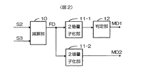
図2は、動き検出部4の一構成例を示す図である。図において減算部10は、現フレームの信号S2と前フレームの信号S3の輝度信号成分の減算を行い、1フレーム間の差分信号成分FDを抽出する。
2値量子化部11−1は、差分信号成分FDの信号レベルが設定値±Tha未満の場合は静止と判定して0、±Tha以上の場合は動きと判定して1の2値信号を出力する。静動ブロック判定部12は、ブロック単位で2値信号の1の有無を検出し、全て0の時は静止ブロックと判定して動き検出信号MD1に0、それ以外の時は動画ブロックと判定して1を出力する。
2値量子化部11−2は、差分信号成分FDの信号レベルが0の場合は静止と判定して0、それ以外は動画と判定して1の動き検出信号MD2を出力する。
【0021】
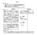
次に、ブロック単位動きベクトル探索部の構成例について説明する。図3はブロック単位動きベクトル探索部5の第1構成例を示す図、図4はこの第1構成例におけるブロック単位動きベクトル探索のフローチャート、図5はブロックマッチング処理における代表点の配列例を示す図である。この第1構成例は、2重代表点ツリー探索処理を行うに好適なものである。
【0022】
図3において、制御部15は、図4に示すステップ1として、動き検出信号MD1に従って、ブロックマッチング第1処理部13とブロックマッチング第2処理部14の動作を制御する。すなわち、動き検出信号MD1が0の静止ブロックでは、ステップ2の一形態として、動きベクトル探索の動作は行わず、ブロック単位動きベクトルBVに0を出力する。一方、動き検出信号MD1が1の動画ブロックでは、以下に述べる動きベクトル探索の動作を行う。
【0023】
ブロックマッチング第1処理部13は、図4に示す第2ステップの探索処理を行う。すなわち、現フレームの信号S2と前フレームの信号S3の輝度信号成分を用いて、予め設定した複数個数の代表動きベクトル(図5に示すように原点近傍領域は密(例えば、代表点間隔が水平方向2画素、垂直方向2ライン)に、周縁部領域では粗(例えば、代表点間隔が水平方向4画素、垂直方向4ライン)となるような2重代表点配列)についてブロックマッチング処理で動き補正誤差を算出し、これが最少となるものを代表動きベクトルBVTに出力する。なお、この探索処理では、既探索の直前のブロックの動きベクトルも代表動きベクトルとして併用することもできる。
【0024】
なお、探索領域に関しては、モーションジャダー妨害が検知される範囲、すなわち、動きの速度が1秒/画面幅、1秒/画面高程度までの範囲をカバーするように、図5に示す水平方向±MX画素、垂直方向±MYラインの領域に限定してもよい。また、テレビ画像はアスペクト比が4:3あるいは16:9の横長画像であるため、水平方向の探索領域を垂直領域の探索領域よりも広く設定することが適している。
【0025】
ブロックマッチング第2処理部14は、図4に示す第3ステップの探索処理を行う。すなわち、現フレームの信号S2と前フレームの信号S3の輝度信号成分を用いて、代表動きベクトルBVTを起点として、x成分が±DXの範囲、y成分が±DYの範囲で定まる動きベクトルについてブロックマッチング処理で動き補正誤差を算出し、これが最少となるものをブロック単位動きベクトルBVに出力する。
【0026】
この結果、ブロック単位動きベクトルの探索は、動画ブロックに限定でき、かつ、代表動きベクトルによる部分探索が可能なため、探索に要する信号処理の演算量を全探索に較べて1桁〜2桁程度低減できる。
【0027】
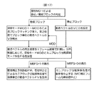
図6はブロック単位動きベクトル探索部5の第2構成例を示す図、図7はこの第2構成例におけるブロック単位動きベクトル探索のフローチャート、図8は動きベクトル発生頻度の計測と探索モード設定の一例を示す図である。この第2構成例は、動きベクトル分布適応探索処理を行うに好適なものである。
【0028】
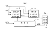
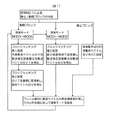
図6に示すように第2構成例は、上述の第1構成例にベクトル分布計測部16を追加した構成で実現する。このベクトル分布計測部16は、動きベクトルの発生頻度を1フレーム期間で計測し、発生頻度の分布形態に応じて探索モード信号MODの設定を行う。これを図7のフローチャートを用いて説明する。すなわち、動き検出信号MD1が0の静止ブロックでは、動きベクトル探索の動作は行わず、ブロック単位動きベクトルBVに0を出力する。一方、動き検出信号MD1が1の動画ブロックでは、以下に述べる探索モード信号MODで定まる探索処理に従い、動きベクトル探索の動作を行う。
【0029】
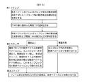
この探索モード信号MODの設定例を図8に示す。同図(a)は動きベクトル発生頻度を計測する領域を示し、図の横軸は動きベクトルのx方向成分の絶対値abs(vx)、縦軸はy方向成分の絶対値abs(vy)である。そして、領域Aでは、0<abs(vx)<=4で0<abs(vy)<=2の範囲、領域Bでは0<abs(vx)<=8で0<abs(vy)<=4のうち領域Aを除く範囲、領域Cでは0<abs(vx)<=12で0<abs(vy)<=6のうち領域AとBを除く範囲、領域Dでは0<abs(vx)<=16で0<abs(vy)<=8のうち領域AとBとCを除く範囲、領域Eではabs(vx)>16又はabs(vy)>8の範囲での動きベクトルの発生個数をそれぞれ1フレーム期間にわたり計測し、これをもとにその発生頻度を算出する。
【0030】
同図(b)は、探索モードの設定条件および探索処理の特性例を示す。
MOD1の探索モードは、領域Aの発生頻度が95%以上の場合で、ブロックマッチング第2処理部14で水平±4画素、垂直±2ラインの範囲を全探索してブロック単位の動きベクトルBVを検出する。
MOD2の探索モードは、領域AとBの発生頻度の合計が95%以上の場合で、ブロックマッチング第2処理部14で水平±8画素、垂直±4ラインの範囲を全探索してブロック単位の動きベクトルBVを検出する。
MOD3の探索モードは、領域AとBとCの発生頻度の合計が95%以上の場合で、ブロックマッチング第1処理部13では密領域からなる代表点動きベクトルで水平±12画素、垂直±6ラインの探索領域をブロックマッチング処理して参照動きベクトルBVTを検出する。ブロックマッチング第2処理部14ではBVTを起点に再探索処理を行い、ブロック単位の動きベクトルBVを検出する。
【0031】
MOD4の探索モードは、領域AとBとCとDの発生頻度の合計が95%以上の場合で、ブロックマッチング第1処理部13では密領域からなる代表点動きベクトルで水平±16画素、垂直±8ラインの探索領域をブロックマッチング処理して参照動きベクトルBVTを検出する。ブロックマッチング第2処理部14ではBVTを起点に再探索処理を行い、ブロック単位の動きベクトルBVを検出する。
MOD5の探索モードは、領域Eの発生頻度が5%以上の場合で、図3の第1の構成例と同様に、水平±24画素、垂直±12ラインの探索領域で2重代表点ツリー探索処理を行い、ブロック単位の動きベクトルBVを検出する。
なお、以上に述べたブロック単位動きベクトル探索部では、動き補正誤差の算出を画像信号の輝度信号成分で行うが、輝度信号成分と色信号成分の両者で行うことも可能である。
【0032】
次に、画素単位動きベクトル生成部6の構成例について説明する。図9は画素単位動きベクトル生成部6の第1構成例を示す図、図10は第1構成例における画素単位動きベクトル生成処理のフローチャート、図11は画素単位動きベクトル生成の動作概略図を示す図である。この第1の構成例は、ブロック予測誤差適応探索処理を行うに好適なものである。
【0033】
図9において、補正誤差算出部17は、図10に示す信号処理フローチャートの第1ステップの処理を行う。すなわち、現フレームの信号S2と前フレームの信号S3の輝度信号成分に対し、ブロック単位動きベクトルBVによる動き補正誤差を算出する。そして、この誤差の値が閾値TH未満のブロックは信号PMBに0、閾値TH以上のブロックは1を出力する。
制御部18は、信号PMBと動き検出信号MD2をもとに、図10の第2、第3ステップの信号処理に必要な制御信号PC1、PC2を生成する。
【0034】
参照動きベクトル生成部19、補正誤差算出部20−1、…、20−Nは、図10の第2ステップの閾値以上の時に、ブロックを水平、垂直方向に細分化したミニブロック毎にミニブロック分割探索処理でミニブロック内の画素の動きベクトルを生成する信号処理を行う。すなわち、制御信号PC1が閾値以上を示すブロックでは、参照動きベクトル生成部19で生成する現ブロックの動きベクトルBVと、図11に示す隣接ブロックに対応する動きベクトルBVul、…、BVdrで、ミニブロック(例えば水平MBX=2、垂直MBY=2の2画素x2ライン)毎に、これを内包する水平4(MBX+2)画素、垂直4(MBY+2)ラインの算出領域での動き補正誤差ER0、ER1、…、ERNを算出する。なお、この動き補正誤差の算出では、現フレームの信号S2と前フレームの信号S3の輝度信号成分、もしくは輝度信号成分及び色差信号成分のいずれかに対して、次の(数1)に示す演算を行う。
【0035】
【数1】

(数1)で、S2(x,y)は算出領域内の現フレームの画素の信号、S3(BV)は動きベクトルBVで位置を移動させた前フレームの画素の信号、abs{ }は絶対値、Σは算出領域内の画素の総和、BVxは動きベクトルBVのx成分、BVyはy成分である。
【0037】
画素動きベクトル設定部21は、図10の第2ステップの閾値未満および第3ステップの信号処理を行う。すなわち、制御信号PC2が閾値未満を示すブロックは、ブロック内の画素に対して現ブロックの動きベクトルBVを画素単位動きベクトルPVに出力する。一方、閾値以上のブロックは、各ミニブロック内の画素に対して動き補正誤差ER0、ER1、…、ERNの内で最少値をとる動きベクトルを画素単位動きベクトルPVに出力する。
また、制御信号PC2で動き検出信号MD2が0の画素に対しては、画素単位動きベクトルPVに0を出力する。
この結果、画素単位の動きベクトルを高精度、かつ、全探索に較べて必要な演算量を1桁〜2桁程度低減できる。
【0038】
図12は画素単位動きベクトル生成部6の第2構成例を示す図、図13は第2構成例における画素単位動きベクトル生成処理のフローチャートである。この第2の構成例は、ブロックミニブロック予測誤差適応探索処理を行うに好適なものである。
【0039】
図12に示す第2構成例においては、補正誤差算出部22及び制御部18における動作が第1の構成例と異なる。
同図において、補正誤差算出部22は、図13に示す信号処理フローチャートの第1ステップの処理を行う。すなわち、現フレームの信号S2と前フレームの信号S3の輝度信号成分に対し、ブロック単位動きベクトルBVによるブロック動き補正誤差PM(画素換算相当)とミニブロック動き補正誤差MBE(画素換算相当)を出力する。
制御部18は、信号PM、MBEと動き検出信号MD2をもとに、図13の第2、第3ステップの信号処理に必要な制御信号PC1、PC2を生成する。まず、ブロック動き補正誤差PMの値に応じて閾値THの値をブロック毎に設定する。例えば、PM<=8ではTH=16、8<PM<=12ではTH=12、12<PM<=16ではTH=8、PM>16ではTH=4に設定する。そして、ミニブロック動き補正誤差MBEと閾値THを比較し、閾値を越えるミニブロックに対しては、第2ステップの閾値以上のミニブロック分割探索の信号処理、閾値未満のミニブロックに対しては第2ステップの閾値未満の信号処理を行うように制御信号を生成する。さらに、動き検出信号MD2が0か1かに応じて第3ステップの信号処理に必要な制御信号を生成する。
なお、参照動きベクトル生成部19、補正誤差算出部20、画素動きベクトル設定部21は、第1の構成例と同様の動作を行うもので、説明は省略する。
【0040】
図14は画素単位動きベクトル生成部6の第3構成例を示す図、図15は第3構成例における画素単位動きベクトル生成処理のフローチャートである。この第3の構成例は、Vエッジ適応探索処理を行うに好適なものである。
【0041】
図14はVエッジ適応探索処理を第1構成例(図9)に適用した場合のブロック構成で、Vエッジ検出部23と制御部26の動作が第1構成例と異なる。
同図においてVエッジ検出部23は、水平周波数の低域成分を通過域とするローパス特性のフィルタHLPF24と垂直周波数の高域成分を通過域とするハイパス特性のフィルタVHPF25との組み合わせで構成し、現フレームの信号S2の輝度信号成分より水平低域・垂直高域のVエッジ信号VEGを抽出する。
制御部26は、ブロック単位動きベクトルBVによる動き補正誤差の値が閾値TH未満か以上かを示す信号PMBとVエッジ信号VEGと動き検出信号MD2をもとに、図15の第2、第3ステップの信号処理に必要な制御信号PC1、PC2を生成する。
【0042】
そして、図15に示すように、第2ステップの閾値以上の時のミニブロック分割探索の信号処理を異にする。すなわち、Vエッジ領域を含むミニブロックでは、ミニブロック(水平MBX、垂直MBY)に対して、これを内包する水平MBX+4、垂直MBYでの算出領域で動き補正誤差を算出し、この値が最小な参照ベクトルで画素単位の動きベクトルPVを生成する。
また、同一のVエッジ領域に含まれる画素に対しては、動きベクトルの修正処理を行う。すなわち、これら画素の動きベクトルを平滑化処理(例えば平均化)で修正し、この修正した動きベクトルをVエッジ領域の画素に割り当てる。
【0043】
一方、Vエッジ領域以外のノ−マル領域では、第1の構成例と同一の動作を行う。
なお、ここに述べたVエッジ適応探索処理は、第2の構成例(図12)に適用することもできる。
以上に述べた如く、動きベクトル探索部は、上述のブロック単位動きベクトル探索部と、画素単位動きベクトル生成部との組み合わせで種々の構成が可能である。
【0044】
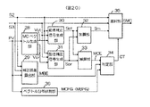
さて、後述する動き補正信号処理部でフレーム単位の動き補正処理を行う場合に好適な動きベクトル探索部の構成例について、次に説明する。図16は動きベクトル探索部の第2構成例を示す図、図17はこの第2構成例における動きベクトル探索のフローチャートである。
【0045】
図16において、ブロックマッチング第1処理部13、ブロックマッチング第2処理部14、ベクトル分布計測部16は前述のブロック単位動きベクトル探索部の第2の構成例(図6)と同一の機能、動作を行う。すなわち、図17に示すように、動画ブロックに対しては探索モード信号MOD1〜MOD5による探索処理(図8参照)でブロック単位の動きベクトルBVの検出を行う。また、静止ブロックに対しては動きベクトルBVに0を設定する。
なお、ベクトル分布計測部16は、図8に示す領域Eの発生頻度が設定値(例えば10%)を越える時はミニブロック分割探索モード信号MBFGに0、設定値未満の時は1を出力する。
【0046】
また、補正誤差算出部17、ミニブロック分割探索部27は、前述の画素単位動きベクトル生成部の第1〜第3の構成例と同様に構成する。そして、モード信号MBFGが1の時は、前述した第1〜第3の構成例と同様なミニブロック分割探索の信号処理を行い、画素単位の動きベクトルPVを生成する。一方、モード信号MBFGが0の時は、後段の動き補正信号処理部では動き補正フレーム内挿処理を行わないため、画素単位の動きベクトルは不要であり、ミニブロック分割探索の信号処理を中止する。
なお、モーションジャダー妨害が目立ちやすい画像(動き補正フレーム内挿処理が必須な画像)は番組全体の1割程度であるため、ミニブロック分割探索処理に要する演算量は、前述の第1〜第3の構成例に較べ、更に1桁程度低減することができる。
また、制御部281は、上述の信号処理の動作に必要な制御信号類を生成するものである。
【0047】
以上で、動きベクトル探索部の説明を終え、次に、動き補正信号処理部7の動き補正内挿フレーム生成部8の構成について説明する。図18は動き補正内挿フレーム生成部8の第1構成例を示す図、図19はMCベクトル生成部28及び動き補正信号生成部30、31の動作を説明するための図である。この第1構成例は、予測誤差適応動き補正処理を行うに好適なものである。
【0048】
MCベクトル生成部28は、画素単位動きベクトルPVより動き補正処理に必要な動き補正ベクトルVctとVprを生成する。フレーム周波数が50Hzの信号をフレーム周波数が60Hzの信号にフレーム数変換する場合を例に、この動作概略を図19(a)〜(c)に示す。フレーム周波数50Hzの順次走査のフレーム順の1から5の信号に対し、同図(a)に示すように、動き補正の信号処理で内挿フレームの信号を生成し、フレーム順1から6のフレーム周波数が60Hzの順次走査の信号に変換する。この際、動き補正ベクトルは、内挿するフレーム位置と合致させる必要がある。そこで、同図(b)に示す様に、画素単位の動きベクトルPVに係数加重する係数値ka,kbをフレーム順に逐次変化させ、(数2)に示す演算で動き補正ベクトルVprとVctを生成する。
【0049】
【数2】
Vpr=PV*ka/(ka+kb)
Vct=−PV*kb/(ka+kb)・・・・・・・・(数2)
【0050】
従って、フレーム順2の内挿フレームは、Vpr=PV*5/6,Vct=−PV*1/6(ka=5,kb=1)、3のものは、Vpr=PV*4/6,Vct=−PV*2/6(ka=4,kb=2)…の如く、時間方向での位置ずれがない動き補正ベクトルを生成する。
【0051】
動き補正信号生成部30では、現フレームの信号S2と動き補正ベクトルVctで動き補正信号Sctを生成する。また、動き補正信号生成部31は、前フレームの信号S3と動き補正ベクトルVprで動き補正信号Sprを生成する。この動作概略を図19(c)に示す。内挿フレームの点A(x,y)の信号は、前フレームの信号S3では、点A(x,y)を動き補正ベクトルVpr(水平方向成分Vprx,垂直方向成分Vpry)で移動させた点A’(x1,y1)=(x+Vprx,y+Vpry)の位置の信号、現フレームの信号S2では点A(x,y)を動き補正ベクトルVct(水平方向成分Vctx,垂直方向成分Vcty)で移動させた点A”(x2,y2)=(x−Vctx,y−Vcty)の位置の信号に対応する。従って、動き補正信号SprとSctは、以下に示す(数3)で生成する。
【0052】
【数3】
Spr=S3(x+Vprx,y+Vpry)
Sct=S2(x−Vctx,y−Vcty)・・・・・・(数3)
【0053】
この信号処理は、動き補正信号生成部に内蔵のメモリ回路の読み出し動作を制御することで実現する。すなわち、メモリ読み出しのアドレスを補正補間動きベクトルVpr,Vctに相当する位置だけずらしたアドレスを生成し、このアドレスで点A’,A”に対応した画素の信号を読み出す。
【0054】
加算部32は、両者の動き補正信号SprとSctとの加算平均を行い、その出力に図19(b)に示したフレーム順2,3,…,6の動き補正内挿フレームの信号Smを得る。
減算部33は、動き補正信号SctとSprとの減算を行い、差分信号成分MCEを検出する。動き補正ベクトルが正確な場合は、動き補正信号SctとSprは同じ値をとるので信号MCEは0になる。しかしながら、動き補正ベクトルが不正確な場合は、動き補正信号SctとSprとで異なる値になり、信号MCEは零以外の値を持つ。
補正誤差算出部29は、ミニブロック単位の動き補正誤差(画素換算相当)を算出し、この値を信号MBEに出力する。
【0055】
判定部34は、信号MBEの値の大小に応じて閾値THの値を適応的に設定する。例えば、MBE<=8ではTH=40、8<MBE<=16ではTH=32、16<MBE<=24ではTH=24、24<MBEではTH=16に設定する。そして、信号MCEが閾値未満の時は0、閾値以上の時は1を制御信号CTに出力する。
【0056】
選択部35は、制御信号CTが0の時は動き補正内挿フレームの信号Sm、制御信号CTが1の時は現フレームの信号S2と前フレームの信号S3のうちで動き補正内挿フレームと時間的な距離の近い信号を選択し、内挿フレームの信号SMCを出力する。この操作で、動きベクトルの不正確さに起因する孤立点的な劣化や動画エッジ周縁部の劣化などの動き補正に固有な画質劣化を大幅に抑圧することができ、高画質化が達成できる。
【0057】
図20は動き補正内挿フレーム生成部8の第2構成例を示す図で、動き速度適応動き補正処理を行うに好適なものである。この第2構成例は、第1の構成例(図18)にベクトル分布計測部36を追加した構成で実現する。
ベクトル分布計測部36では、画素単位の動きベクトルPVのうち図8(a)に示した領域Eに相当する動きベクトルの1フレーム期間での発生頻度を計測し、これが設定値(例えば10%以上)を越える場合は動き補正モード信号MCFGに0、設定値未満の場合は1を出力する。
判定部34は、動き補正モード信号MCFGが0の時は、選択部35で該当する1フレーム期間は現フレームの信号S2を選択制御する制御信号CTを出力する。一方、動き補正モード信号MCFGが1の時は、第1の構成例と同様の動作を行い、信号MCEが信号MBEで定まる閾値以上では1、未満では0の制御信号CTを出力する。
【0058】
なお、本構成では、ベクトル分布計測部36を省略し、代わりに、前述した図16の動きベクトル探索部におけるミニブロック分割探索モード信号MBFGを動き補正モード信号として使用する構成で実現することも可能である。
以上に述べた如く、本発明の第1の実施例によれば、動きベクトル探索、生成の信号処理に要する演算量が少なく、かつ、動き補正処理に起因する画質劣化の少ない画像信号の動き補正フレーム数変換装置が実現できる。そして、高画質化、低コスト化に顕著な効果を得ることができる。
【0059】
次に、本発明の第2の実施例について、図21〜図22を用いて説明する。
図21は本実施例のブロック構成図で、先の第1の実施例(図1)の動き補正信号処理部のメモリ部9を省略し、代わりにフレームレートアップ部37をIP変換部1と1フレーム遅延部2との間に配置して構成する。
IP変換部1で飛び越し〜順次の走査変換した順次走査の信号系列S2は、フレームレートアップ部37でコマ繰り返し処理でフレーム数変換を行い、例えば、フレーム周波数50Hzの信号系列S2をフレーム周波数60Hzの信号系列S5に変換する。
【0060】
この動作概略を図22に示す。S2(50Hz)フレーム順1,2,3,4,5,1,2,…の信号系列に対し、このフレーム順1のフレームを2度繰り返して、S5(60Hz)のフレーム順1,1,2,3,4,5,1,1,2,…の信号系列に変換する。そして、このS5を現フレームの信号系列、これを1フレーム遅延部2で1フレーム期間遅延させた信号S6を前フレームの信号系列として、動きベクトル探索部3と動き補正信号処理部7で第1の実施例と同様の信号処理を行う。従って、現フレームと前フレームの信号系列が同一フレーム順1の場合は静止画像となり、フレームの全ての動きベクトルが0の処理が行われ、出力の信号系列S4(60Hz)はフレーム順1の信号を得る。一方、現フレームと前フレームの信号系列が異なるフレーム順の時は、出力の信号系列S4は動き補正処理で生成した信号系列(図中にMCで表示)を得る。
【0061】
本発明の第2の実施例によれば、第1の実施例と同様、動きベクトル探索、生成の信号処理に要する演算量が少なく、かつ、動き補正処理に起因する画質劣化の少ない画像信号の動き補正フレーム数変換装置が実現できる。そして、高画質化、低コスト化に顕著な効果を得ることができる。
【0062】
次に、本発明の第3の実施例について、図23〜25を用いて説明する。なお、本実施例は、動きベクトル探索において変換ベクトル探索処理を行うに好適なものである。
図23は本実施例のブロック構成図であり、ブロック単位動きベクトル探索部38の構成、動作のみが先の第1の実施例(図1)と異なる。
図24は、この構成を示す図である。図24において、Pベクトル変換部39、Bベクトル変換部40は、画像符号化で使用する動きベクトル情報MVのベクトル変換処理を行い、それぞれ1フレーム当たりの変換ベクトルMVpとMVbを生成する。
【0063】
図25はこの動作概略を示す図である。画像符号化、特に、国際標準のMPEGビデオ符号化では、同図(a)に示すように、画像信号シ−ケンスをIピクチャ、Pピクチャ、Bピクチャに分け、Iピクチャではフレーム内DCT(離散コサイン変換)符号化、Pピクチャでは一方向MC符号化+DCT符号化、Bピクチャでは双方向MC符号化+DCT符号化を行う。
同図(b)は、Pピクチャの符号化に使用する動きベクトルPV1,PV2,…を示す。この動きベクトルは画像信号シ−ケンスのPピクチャ間のnフレーム(図ではn=3)での動きベクトルに相当する。従って、Pベクトル変換部39では、この動きベクトルを1/n(図では1/3)に変換したPV1/3,PV2/3,…で変換ベクトルMVpを生成する。
同図(c)はBピクチャの符号化に使用する動きベクトルBV11,BV12、BV21,BV22…を示す。このうち、BV11,BV21,BV31,…は1フレーム間の動きベクトルに相当している。従って、Bベクトル変換部40では、これらの動きベクトルで変換動きベクトルMVbを生成する。
【0064】
図24に戻り、判定部41では、動き検出信号MD1が1の動画ブロックに対し、変換ベクトルMVp,MVbによるブロック単位の動き補正誤差を算出し、値の小さいものを代表動きベクトルBVTに出力する。
ブロックマッチング第2処理部14は、代表動きベクトルBVTを起点とする再探索処理を行い、ブロック単位の動きベクトルBVを検出する。なお、静止ブロックに対しては、BVに0を出力する。
制御部42は、これらの動作に必要な制御信号類を生成する。
本発明の第3の実施例によれば、第1、第2の実施例に較べて、動きベクトル探索、生成の信号処理に要する演算量が更に少ない画像信号の動き補正フレーム数変換装置が実現できる。そして、高画質化、低コスト化に顕著な効果を得ることができる。
【0065】
次に、本発明の第4の実施例を図26のブロック構成図に示す。本実施例は、先の第3の実施例(図23)の動き補正信号処理部のメモリ部9を省略し、代わりに第2の実施例(図21)に示したフレームレートアップ部37をIP変換部1と1フレーム遅延部2との間に配置して構成する。なお、この動作は前述の第1〜第3の実施例から容易に理解できるため説明は省略する。
本発明の第4の実施例によれば、第3の実施例と同様、動きベクトル探索、生成の信号処理に要する演算量が更に少ない画像信号の動き補正フレーム数変換装置が実現できる。そして、高画質化、低コスト化に顕著な効果を得ることができる。
【0066】
次に、本発明の第5の実施例を図27〜図28を用いて説明する。本実施例は、シーンチェンジの領域で動きベクトル探索や動き補正フレーム内挿の信号処理を中止する動作を行うに好適なものである。
図27はこのブロック構成図であり、第1の実施例(図1)の構成にシーンチェンジ検出部391を追加して実現する。
【0067】
シーンチェンジ検出部391は、1フレーム期間でのフレーム間差分信号成分の発生形態をもとにシーンチェンジの発生したフレームを検出する動作を行う。この一構成例を図28に示す。減算部401は、現フレームの信号S2と前フレームの信号S3の輝度信号成分の減算演算を行い、1フレーム間の差分成分FDを抽出する。一般に、シーンチェンジの領域では、画像の内容が切り替わるため、差分成分FDの信号レベルは比較的大きな値を持つ。そこで、2値量子化部411は比較的高いレベルの閾値±Thbで信号FDを画素毎に2値量子化する。そして、閾値±Thb未満の画素は0、閾値を越える画素は1を信号QSに出力する。1フレーム累積部421は、信号QSが1のものの画素の数を1フレーム期間で計測し、1フレーム期間の累積値AQを出力する。判定部431は、累積値AQの値が全画面の半分以上の画素数で、かつ、その発生が1フレーム期間に限られる場合をシーンチェンジの発生したフレームと判定する。この理由は、画面全体が一様な速度で動く水平パンや上下パンの動きを誤ってシーンチェンジと検出する誤動作を避けるためである。そして、信号SCFGにシーンチェンジの発生したフレームでは1、それ以外のフレームでは0を出力する。
【0068】
図27に戻り、動きベクトル探索部3と動き補正信号処理部7は、信号SCFGが1のシーンチェンジが発生したフレームでは、動きベクトル探索や動き補正フレーム内挿の信号処理を中止する。そして、このフレームでは現フレームの信号S2を信号系列S4に出力する。
一方、信号SCFGが0のフレームでは、動きベクトル探索部3と動き補正信号処理部7は、第1の実施例と同一の信号処理の動作を行い、信号系列S4では動き補正フレーム内挿処理でフレーム数を変換した信号系列を得る。
本発明の第5の実施例によれば、シーンチェンジ領域における動きベクトル探索や生成のための膨大な演算量の発生が回避でき、第1の実施例に較べて、動きベクトル探索、生成の信号処理に要する演算量が更に少ない画像信号の動き補正フレーム数変換装置が実現できる。そして、高画質化、低コスト化に顕著な効果を得ることができる。
【0069】
次に、本発明の第6〜第8の実施例を図29〜図31の図面で説明する。これらは、いずれもシーンチェンジの領域では動きベクトル探索や動き補正フレーム内挿の信号処理を中止する動作を行うに好適なものである。
図29は第6の実施例のブロック構成例図で、第2の実施例(図21)の構成にシーンチェンジ検出部391を追加して実現したものである。
図30は第7の実施例のブロック構成例図で、これは第3の実施例(図23)の構成にシーンチェンジ検出部391を追加して実現したものである。
また、図31は第8の実施例のブロック構成例図で、これは第4の実施例(図26)の構成にシーンチェンジ検出部391を追加して実現したものである。
なお、これら実施例における動作はこれまでの説明で容易に理解できるため、説明は省略する。
本発明の第6〜第8の実施例によれば、第5の実施例と同様、動きベクトル探索、生成の信号処理に要する演算量が更に少ない画像信号の動き補正フレーム数変換装置が実現できる。そして、高画質化、低コスト化に顕著な効果を得ることができる。
【0070】
本発明の第9の実施例について、図32〜図37を用いて説明する。
図32は、本実施例のブロック構成図である。同図に示すように、先の第1の実施例(図1)では、IP変換部を、動きベクトル探索部の前段に配置して構成するのに対して、本実施例では、その後段に配置して構成する。
1フレーム遅延部2は、飛び越し走査の入力画像信号S1(輝度信号成分と色差信号成分)から、これを1フレーム期間遅延させた信号S20を生成する。この信号S1及びS20は、動きベクトル探索部3と動き補正信号処理部7に供給される。
【0071】
動きベクトル探索部3は、動き検出部4、ブロック単位動きベクトル探索部5、画素単位動きベクトル生成部6で構成する。
動き検出部4は、現フレームの信号系列S1と、前フレームの信号系列S20の輝度信号成分との減算処理で1フレーム間の差分信号を抽出し、これを2値量子化して動き検出信号MD1、MD2を出力する。この構成及び動作は、先に説明した第1の実施例の動き検出部(図2)と同様である。但し同図及びその説明において、S2をS1、S3をS20と読み替えるものとする。
【0072】
ブロック単位動きベクトル探索部5は、ブロック単位(例えば16画素x16ラインあるいは8画素x8ライン)で動きベクトルを検出する。すなわち、動き検出信号MD1が0のブロックは静止ブロックと判定し、ブロック単位動きベクトルBVに0を出力する。一方、MD1が1のブロックは動画ブロックと判定し、信号S1とS20の輝度信号成分に対して、前述した2重代表点ツリー探索処理あるいは動きベクトル分布適応探索処理を行い、ブロック単位動きベクトルBVを検出する。この構成及び動作は、先に説明した第1の実施例のブロック単位動きベクトル探索部(図3〜図8)と同様である。但し同図及びその説明において、S2をS1、S3をS20とそれぞれ読み替えるものとする。
【0073】
画素単位動きベクトル生成部6は、ミニブロック分割探索処理で画素単位動きベクトルPVを生成する。すなわち、前述したブロック予測誤差適応探索処理、ブロックミニブロック予測誤差適応探索処理あるいはVエッジ適応探索処理でミニブロック単位(例えば2画素x2ライン)で画素単位動きベクトルPVを検出する。また、動き検出信号MD2が0の画素は静止画素と判定してPVに0を割り当てる。この構成及び動作は、先に説明した第1の実施例の画素単位動きベクトル生成部(図9〜図15)と同様である。但し同図及びその説明において、S2をS1、S3をS20とそれぞれ読み替えるものとする。
【0074】
また、後述する動き補正信号処理部でフレーム単位の動き補正処理を行う場合に好適な動きベクトル探索部の構成及び動作についても、先に説明した第1の実施例の動きベクトル探索部(図16〜図17)と同様である。但し同図及びその説明において、S2をS1、S3をS20とそれぞれ読み替えるものとする。
【0075】
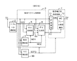
動き補正信号処理部7は、IP変換部71とMCフレーム数変換部72で構成する。
IP変換部71は、動きベクトルPVと1フレーム間差分信号成分の大小に応じて動き適応処理の飛び越し−順次の走査変換を行い、順次走査の信号系列S30を生成する。この具体的な構成については後述する。
MCフレーム数変換部72は、画素単位動きベクトルPVをもとに動き補正ベクトルを作り、順次走査の信号系列S30の画像の位置をこの動き補正ベクトルで移動させた信号で内挿フレームの信号系列を生成し、この出力に動き補正フレーム数変換処理でフレーム周波数をアップした順次走査の画像信号系列S4(輝度信号成分と色差信号成分)を得る。この具体的な構成についても後述する。
以上で全体ブロック構成図の説明を終え、以下、本実施例における動き補正信号処理部7の構成について詳述する。
【0076】
図33は、IP変換部71の一構成例で、動きベクトルを利用した動き適応処理の飛び越し−順次の走査変換を行うに好適なものである。
この構成を同図(a)に示す。MA補間部78は走査変換に必要な補間走査線の信号を生成する。このうち、動画補間信号生成部79は、フィ−ルド内処理(例えば、上下の走査線の信号の平均値)を行い、動画に適した補間走査線信号SMを生成する。また、静止補間信号生成部80は、フィ−ルド間処理(例えば、前フレームの走査線の信号)を行い、静止画に適した補間走査線信号SSを生成する。
係数加重部81−1は動き係数k、81−2は1−kを加重し、加算部82で両者の信号を加算して、補間走査線の信号を生成する。
【0077】
動き係数生成部83は、同図(b)に示すように、1フレーム間の輝度信号差分成分の絶対値|S1−S20|と、動きベクトルPVのスカラ−量|PV|の値の大小に応じて、動き係数の係数値kを設定する。すなわち、スカラ−量|PV|が小から大となるに従い、傾斜が漸次きつくなる特性の直線で係数値kを設定する。従って、|S1−S20|が同一の値でも、動きの速度に比例してkの値も大きく設定でき、従来技術に較べて、画像の動きにより整合した動き適応信号処理が可能になる。
倍速変換部84は、生成した補間走査線信号とS1との時間軸の1/2圧縮と時系列多重の信号処理を行い、順次走査の信号系列S30を出力する。
【0078】
次に、このMCフレーム数変換部72について、図34〜図37を用いて説明する。
図34は、第1の構成例で、予測誤差適応動き補正処理を行うに好適なものである。
図34の構成例において、1フレームメモリ部85は、順次走査の現フレームの信号系列S30を1フレーム期間遅延させた前フレームの信号系列S3Pを生成する。
MCベクトル生成部86は、飛び越し走査系列で検出した画素単位動きベクトルPVより動き補正処理に必要な動き補正ベクトルVctとVprを生成する。そして、動き補正信号生成部87では、現フレームの信号S30と動き補正ベクトルVctで動き補正信号Sctを生成する。また、動き補正信号生成部88は、前フレームの信号S3Pと動き補正ベクトルVprで動き補正信号Sprを生成する。
【0079】
これらの動作概略は、先の図19(a)〜(c)で説明したとおりである。但し、同図及びその説明において、PVをPV’と読み替えるものとする。ここでPV’は、順次走査系列での画素単位の動きベクトルで、飛び越し走査系列で検出した動きベクトルPVとはPV’=PV/2の関係が成立する。従って、フレーム順2の内挿フレームは、Vpr=PV’*5/6(PV*5/12),Vct=−PV’*1/6(−PV*1/12)(ka=5,kb=1)、フレーム順3のものは、Vpr=PV’*4/6(PV*4/12),Vct=−PV’*2/6(−PV*2/12)(ka=4,kb=2)…の如く、時間方向での位置ずれがない動き補正ベクトルを生成する。
【0080】
加算部89は、両者の動き補正信号SprとSctとの加算平均を行い、フレーム順2,3,…,6の動き補正内挿フレームの信号Smcを得る。
減算部90は、動き補正信号SctとSprとの減算を行い、差分信号成分MCEを検出する。動き補正ベクトルが正確な場合は、動き補正信号SctとSprは同じ値をとるので信号MCEは0になる。しかしながら、動き補正ベクトルが不正確な場合は、動き補正信号SctとSprとで異なる値になり、信号MCEは零以外の値を持つ。
補正誤差算出部91は、ミニブロック単位の動き補正誤差(画素換算相当)を算出し、この値を信号MBEに出力する。
【0081】
判定部92は、信号MBEの値の大小に応じて閾値THの値を適応的に設定する。例えば、MBE<=8ではTH=40、8<MBE<=16ではTH=32、16<MBE<=24ではTH=24、24<MBEではTH=16に設定する。そして、信号MCEが閾値未満の時は0、閾値以上の時は1を制御信号SLに出力する。
【0082】
選択部93は、制御信号SLが0の時は動き補正内挿フレームの信号Smc、制御信号SLが1の時は現フレームの信号S30と前フレームの信号S3Pのうちで動き補正内挿フレームと時間的な距離の近い信号を選択し、内挿フレームの信号S50を出力する。この操作で、動きベクトルの不正確さに起因する孤立点的な劣化や動画エッジ周縁部の劣化などの動き補正に固有な画質劣化を大幅に抑圧することができ、高画質化が達成できる。
メモリ部94は、以下の書き込み、読み出し動作を行い、フレーム数変換した信号系列S4を得る。書き込み動作では、現フレームの信号S30のフレーム順1の信号と、信号S50のフレーム順2〜6の信号を書き込む。一方、読み出し動作ではフレーム順1から6の信号を順次読み出す。
【0083】
図35は、この第2の構成例のブロック構成図で、動き速度適応動き補正処理を行うに好適なものである。これは第1の構成例(図34)にベクトル分布計測部95を追加した構成で実現する。
ベクトル分布計測部95では、画素単位の動きベクトルPVのうち、先の図8(a)に示した領域Eに相当する動きベクトルの1フレーム期間での発生頻度を計測し、これが設定値(例えば10%以上)を越える場合は動き補正モード信号MCFGに0、設定値未満の場合は1を出力する。
【0084】
判定部92は、動き補正モード信号MCFGが0の時は、選択部93で該当する1フレーム期間では現フレームの信号S30を選択制御する制御信号SLを出力する。一方、動き補正モード信号MCFGが1の時は、第1の構成例と同様の動作を行い、信号MCEが信号MBEで定まる閾値以上では1、未満では0の制御信号SLを出力する。
なお、本構成では、ベクトル分布計測部95を省略し、代わりに、前述した図16の動きベクトル探索部におけるミニブロック分割探索モード信号MBFGを動き補正モード信号として使用する構成で実現することも可能である。
【0085】
図36は、この第3の構成例で、図34の第1の構成例の最終段のメモリ部94を省略し、代わりにフレームレートアップ部97を先頭に配置した形態で実現する。
フレームレートアップ部97は、コマ繰り返し処理でフレーム数変換を行い、例えば、フレーム周波数50Hzの順次走査の信号系列S30をフレーム周波数60Hzの信号系列S10に変換する。このS10を現フレームの信号系列、これを1フレーム遅延部35で1フレーム期間遅延させた信号S10Pを前フレームの信号系列として、以降、第1の構成例と同様の信号処理を行う。
【0086】
この動作概略は、先の図22で説明したとおりである。但し、同図及びその説明において、S2をS30、S5をS10、S6をS10Pとそれぞれ読み替えるものとする。従って、現フレームと前フレームの信号系列が同一フレーム順1の場合は静止画像となり、フレームの全ての動きベクトルが0の処理が行われ、出力の信号系列S4(60Hz)はフレーム順1の信号を得る。一方、現フレームと前フレームの信号系列が異なるフレーム順の時は、出力の信号系列S4は動き補正処理で生成した信号系列(図22中にMCで表示)を得る。
【0087】
図37は、この第4の構成例で、図35の第2の構成例の最終段のメモリ部94を省略し、代わりにフレームレートアップ部97を先頭に配置した形態で実現する。この動作に関しては、上述の構成例と同様なため、説明は省略する。
本発明の第9の実施例によれば、動きベクトル探索、生成の信号処理に要する演算量が少なく、かつ、動き補正処理に起因する画質劣化の少ない画像信号のフレーム数変換装置が実現できる。そして、高画質化、低コスト化に顕著な効果を得ることができる。
【0088】
本発明の第10の実施例について、図38を用いて説明する。本実施例は、動きベクトル探索において変換ベクトル探索処理を行うに好適なものである。同図はこのブロック構成例を示す図であり、ブロック単位動きベクトル探索部98の構成、動作のみが先の第9の実施例(図32)と異なる。このブロック単位動きベクトル探索部98の構成と動作は、先の図24〜図25で説明したとおりである。但し同図及びその説明において、S2をS1、S3をS20とそれぞれ読み替えるものとする。
本発明の第10の実施例によれば、動きベクトル探索、生成の信号処理に要する演算量が更に少ない画像信号のフレーム数変換装置が実現できる。そして、高画質化、低コスト化に顕著な効果を得ることができる。
【0089】
本発明の第11の実施例を図39を用いて説明する。これは、シーンチェンジの領域では動きベクトル探索や動き補正フレーム内挿の信号処理を中止する動作を行うに好適なものである。同図はこのブロック構成例を示す図で、第9の実施例(図32)の構成にシーンチェンジ検出部99を追加して実現する。シーンチェンジ検出部99では、1フレーム期間でのフレーム間差分信号成分の発生形態をもとにシーンチェンジの発生したフレームを検出する動作を行う。この構成と動作は、先の図28で説明したとおりである。但し同図及びその説明において、S2をS1、S3をS20とそれぞれ読み替えるものとする。
【0090】
図39に戻り、動きベクトル探索部3と動き補正信号処理部7は、信号SCFGが1のシーンチェンジが発生したフレームでは、動きベクトル探索や動き補正フレーム内挿の信号処理を中止する。一方、信号SCFGが0のフレームでは、動きベクトル探索部3と動き補正信号処理部7は、第1の実施例と同一の信号処理の動作を行い、信号系列S4に動き補正フレーム内挿処理でフレーム数を変換した信号系列を得る。
本発明の第11の実施例によれば、シーンチェンジ領域における動きベクトル探索や生成のための膨大な演算量の発生が回避でき、第9の実施例に較べて、動きベクトル探索、生成の信号処理に要する演算量が更に少ない画像信号のフレーム数変換装置が実現できる。そして、高画質化、低コスト化に顕著な効果を得ることができる。
【0091】
本発明の第12の実施例を図40を用いて説明する。これは、第10の実施例(図38)の構成にシーンチェンジ検出部99を追加して実現したものである。この動作は、上述の実施例の説明で容易に理解できるので説明は省略する。そして、第11の実施例と同様、動きベクトル探索、生成の信号処理に要する演算量が更に少ない画像信号のフレーム数変換装置が実現できる。そして、高画質化、低コスト化に顕著な効果を得ることができる。
【0092】
次に、本発明のフレーム数変換装置をテレビジョン受像機に適用した実施例について、図41〜図44の図面を用いて説明する。
【0093】
図41は、この第1の実施例のブロック構成例で、画像を順次走査の形態で表示するに好適なものである。図において、チューナー部44は、地上放送信号TVをベースバンド帯域のテレビジョン信号に復調する。 BSチューナー部45は、衛星放送信号BSをベースバンド帯域のテレビジョン信号に復調する。デコーダ部46は、アナログ方式のテレビジョン信号の所定の復調処理を行い、輝度信号と色差信号を復調する。IRD部47は、デジタル方式のテレビジョン信号の所定の復号化処理を行い、輝度信号と色差信号を復調する。外部入力信号Exには、VCR等のパッケージメディアやPC画像などの輝度信号と色差信号を入力する。スイッチ部48は、制御部54の制御信号で指定する信号系列の選択を行う。
【0094】
IP変換部49は、飛び越し走査の信号系列に対しては、例えば動き適応の走査変換の信号処理を行い、順次走査の信号系列に変換する。MCフレーム数変換部50は、本発明のフレーム数変換装置に相当し、動き補正フレーム内挿処理でフレーム周波数をアップした信号系列を生成する。例えば、PAL方式のフレーム周波数50Hzの信号の50Hz→60Hz変換では、前述の実施例と同様にフレーム順1〜5の入力信号系列からフレーム順1〜6(2〜6は動き補正フレーム内挿処理で生成)の信号系列を生成する。また、50Hz→75Hz変換では、フレーム順1〜2の入力信号系列からフレーム順1〜3(2〜3は動き補正フレーム内挿処理で生成)の信号系列を生成する。あるいは、50Hz→100Hz変換では、フレーム順1の入力信号系列からフレーム順1〜2(2は動き補正フレーム内挿処理で生成)の信号系列を生成する。
【0095】
スケーリング処理部51は、画像サイズの拡大/縮小、アスペクト比の変換、走査線数の変換などの信号処理を行う。画質改善部52は、鮮鋭度改善や輝度階調補正などの画質改善信号処理と色空間変換による3原色信号への変換を行う。順次表示部53は、フレーム周波数が60Hz、又は75Hzか100Hzの順次走査の形態で画像表示を行う。
【0096】
リモコン受信部55は、ユーザがリモコン端子で操作する各種ユーザ情報(チャネル選択、表示モードなど)を受信する。制御部54は、この受信した各種ユーザ情報に応じて、各部の動作に必要な制御信号類(図面には明示せず)を生成し、被制御部58に出力する。
【0097】
図42は、この第2の実施例のブロック構成例で、画像を飛び越し走査の形態で表示するに好適なものである。これは、上述した図41の構成にPI変換部56を追加し、インターレース表示部57で飛び越し走査の形態の画像を表示する。PI変換部56は、順次走査の信号系列の走査線の2:1の間引き処理を行い、飛び越し走査の信号系列に変換する信号処理を行う。また、インターレース表示部57は、フィールド周波数が60Hz、又は75Hzか100Hzの飛び越し走査の形態で画像表示を行う。なお、この他のブロックは図41のものと同一の動作を行うので、説明は省略する。
【0098】
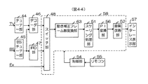
図43は、この第3の実施例のブロック構成例で、画像を順次走査の形態で表示するに好適なものである。これは、上述した図41のIP変換部41及びMCフレーム数変換部50に代えて、動き補正フレーム数変換部63を設けたものである。この動き補正フレーム数変換部63は、本発明のフレーム数変換装置に相当し、動き補正フレーム内挿処理でフレーム周波数をアップした順次走査の信号系列を生成する。例えば、PAL方式のフレーム周波数50Hzの信号の50Hz→60Hz変換では、前述の実施例と同様にフレーム順1〜5の入力信号系列からフレーム順1〜6(2〜6は動き補正フレーム内挿処理で生成)の信号系列を生成する。また、50Hz→75Hz変換では、フレーム順1〜2の入力信号系列からフレーム順1〜3(2〜3は動き補正フレーム内挿処理で生成)の信号系列を生成する。あるいは、50Hz→100Hz変換では、フレーム順1の入力信号系列からフレーム順1〜2(2は動き補正フレーム内挿処理で生成)の信号系列を生成する。なお、この他のブロックは図41のものと同一の動作を行うので、説明は省略する。
【0099】
図44は、この第4の実施例のブロック構成例で、画像を飛び越し走査の形態で表示するに好適なものである。これは、上述した図43の構成にPI変換部56を追加し、インターレース表示部57で飛び越し走査の形態の画像を表示する。このPI変換部56及びインターレース表示部57は、図42の第2の実施例で説明したものと同じものである。この他のブロックは図43のものと同一の動作を行うので、説明は省略する。
これらのテレビジョン受像機の実施例によれば、マルチソース対応の高画質な装置を低コストで実現することができる。
【0100】
以上で実施の形態の説明を終了するが、本発明は、PAL−NTSCテレビジョン信号の方式変換、PAL50Hz−60Hz/75Hz/100Hz変換、フィルム画像(フレーム周波数24Hz/30Hz)−60Hz変換、テレビジョン信号−パソコン画像信号変換など、各種のフレーム数変換装置に適用し、高画質化・低コスト化に顕著な効果を有する。
【0101】
このように本発明では、動き補正に必要な動きベクトル探索に要する信号処理の演算量や回路規模が小さく、また、動き補正に固有な画質劣化を抑圧した動き補正フレーム変換装置が実現できる。このため、各種のフレーム数変換装置の高画質化・低コスト化に顕著な効果が得られる。
また、本発明をテレビジョン受像機に適用して、マルチソース対応の高画質で低コストの受像機を実現することができる。また、受像機の多機能化にも顕著な効果がある。
【0102】
【発明の効果】
本発明によれば、高画質でしかも回路規模の小さい画像信号のフレーム数変換方法および装置を得ることができる。
【図面の簡単な説明】
【図1】本発明の第1の実施例のブロック構成図である。
【図2】動き検出部の一構成例を示す図である。
【図3】ブロック単位動きベクトル探索部の第1構成例を示す図である。
【図4】第1構成例のブロック単位動きベクトル探索のフローチャートである。
【図5】ブロックマッチング第1処理における代表点の配列図である。
【図6】ブロック単位動きベクトル探索部の第2構成例を示す図である。
【図7】第2構成例のブロック単位動きベクトル探索のフローチャートである。
【図8】(a)は動きベクトル発生頻度の計測の一例を、(b)は探索モード設定の一例をそれぞれ示す図である。
【図9】画素単位動きベクトル生成部の第1構成例を示す図である。
【図10】第1構成例の画素単位動きベクトル生成処理のフローチャートである。
【図11】画素単位動きベクトル生成の動作概略を示す図である。
【図12】画素単位動きベクトル生成部の第2構成例を示す図である。
【図13】第2構成例の画素単位動きベクトル生成処理のフローチャートである。
【図14】画素単位動きベクトル生成部の第3構成例を示す図である。
【図15】第3構成例の画素単位動きベクトル生成処理のフローチャートである。
【図16】動きベクトル探索部の他の構成例を示す図である。
【図17】動きベクトル探索の信号処理フローチャートである。
【図18】動き補正内挿フレーム生成部の第1構成例を示す図である。
【図19】(a)、(b)はそれぞれMCベクトル生成部の動作概略を、(c)は動き補正信号生成部の動作概略を示す図である。
【図20】動き補正内挿フレーム生成部の第2構成例を示す図である。
【図21】本発明の第2の実施例のブロック構成図である。
【図22】(a)〜(d)はそれぞれフレームレートアップ部の動作概略を説明するための図である。
【図23】本発明の第3の実施例のブロック構成図である。
【図24】ブロック単位動きベクトル探索部の一構成例を示す図である。
【図25】(a)〜(c)はそれぞれベクトル変換部の動作概略を示す図である。
【図26】本発明の第4の実施例のブロック構成図である。
【図27】本発明の第5の実施例のブロック構成図である。
【図28】シーンチェンジ検出部の一構成例を示す図である。
【図29】本発明の第6の実施例のブロック構成図である。
【図30】本発明の第7の実施例のブロック構成図である。
【図31】本発明の第8の実施例のブロック構成図である。
【図32】本発明の第9の実施例のブロック構成図である。
【図33】(a)、(b)はそれぞれIP変換部の一構成例を示す図である。
【図34】MCフレーム数変換部の第1構成例を示す図である。
【図35】MCフレーム数変換部の第2構成例を示す図である。
【図36】MCフレーム数変換部の第3構成例を示す図である。
【図37】MCフレーム数変換部の第4構成例を示す図である。
【図38】本発明の第10の実施例のブロック構成図である。
【図39】本発明の第11の実施例のブロック構成図である。
【図40】本発明の第12の実施例のブロック構成図である。
【図41】本発明に係るテレビジョン受像機の第1の実施例を示す図である。
【図42】本発明に係るテレビジョン受像機の第2の実施例を示す図である。
【図43】本発明に係るテレビジョン受像機の第3の実施例を示す図である。
【図44】本発明に係るテレビジョン受像機の第4の実施例を示す図である。
【符号の説明】
1 IP変換部
2 1フレーム遅延部
3 動きベクトル探索部
4 動き検出部
5 ブロック単位動きベクトル探索部
6 画素単位動きベクトル生成部
7 動き補正信号処理部
8 動き補正内挿フレーム生成部
9 メモリ部[0001]
BACKGROUND OF THE INVENTION
The present invention relates to an image signal frame number conversion method and apparatus, and more particularly to a frame number conversion method and apparatus suitable for converting the frame number by motion correction signal processing.
[0002]
[Prior art]
In recent years, with the development of multimedia, television receivers are also required to have a function of displaying signals of different image formats such as various types of television signals and PC image signals. In addition, an image display function by sequential scanning is required as a function corresponding to high image quality and a flat display. In order to realize these functions, it is necessary to convert the number of input signals into the format of the image display unit and to perform signal processing such as frame number conversion and sequential scanning. When this signal processing is performed by a simple method such as frame repetition or frame dropping, image quality degradation such as motion judder in which smoothness is lost in a moving image occurs.
[0003]
The motion correction frame number conversion process is a technique for avoiding this kind of image quality degradation, and generates an interpolated frame signal by moving the image position of the previous and next frames using a motion vector. With regard to this motion correction frame number conversion process, for example, Japanese Patent Laid-Open No. 7-170496 discloses a technique for efficiently searching for motion vectors. Japanese Patent Application Laid-Open No. 7-336650 discloses a technique for avoiding deterioration such as a reduction in resolution at a moving image edge peripheral edge inherent to motion correction.
[0004]
[Problems to be solved by the invention]
However, in these conventional techniques, the former has a problem in the accuracy of motion detection, and the latter has a problem in the complexity of signal processing. That is, in the prior art, the signal processing circuit scale increases when trying to improve the image quality, and conversely, if the signal processing circuit scale is reduced, image quality deterioration cannot be sufficiently eliminated.
[0005]
Accordingly, it is an object of the present invention to provide a method and apparatus for converting the number of frames of an image signal with high image quality and a small circuit scale.
[0006]
[Means for Solving the Problems]
The purpose of the above is to detect a motion vector in a block unit by block matching processing for a moving image block detected from an image signal, and the motion of the current block and an adjacent block according to the magnitude of the motion correction error of the detected block unit motion vector. Generates a motion vector in units of pixels from the vector, generates an interpolation frame of the image signal according to the magnitude of the motion correction error of the motion vector in pixel unit, and converts the number of frames of the image signal using this interpolation frame This is achieved by a method for converting the number of frames of an image signal.
[0007]
Also, in the frame number conversion device according to the present invention, a motion detection unit that detects a still block or a moving image block based on an image signal, and a block unit motion vector that detects a block-based motion vector by block matching processing on the moving image block A search unit, a pixel unit motion vector generation unit that generates a pixel unit motion vector from the motion vectors of the current block and adjacent blocks according to the magnitude of the motion correction error of the detected block unit motion vector, and a pixel unit motion vector A motion correction interpolation frame generation unit that generates an interpolation frame of the image signal according to the magnitude of the motion correction error. Here, as the image signal, an interlaced scanning image signal or a progressive scanning image signal may be used, but the apparatus configurations of both are basically the same. However, there are differences in the specific configuration, and these will be described later.
[0008]
Specifically, the present invention uses the following technical means. That is, in order to greatly reduce the amount of calculation required for the motion vector search process, the following two-stage signal processing of the block unit motion vector search process and the pixel unit motion vector generation process is employed.
[0009]
First, in block unit motion vector search processing, a motion vector is searched by block matching processing, but a block in which motion is not detected by a frame difference signal (hereinafter abbreviated as still block) and a block in which motion is detected (hereinafter abbreviated as moving image block). ) And the search process is performed with one of the following three types only for the moving image block.
(1) Double representative point tree search processing: The representative motion vectors that are preset in the vicinity of the origin are dense and the peripheral portion is roughly set as a reference motion vector having the smallest motion correction error. The motion vector in the block unit is detected by re-searching the one having the smallest motion correction error.
(2) Motion vector distribution adaptive search processing: Select one of a plurality of types of search modes having different search regions and representative motion vector arrangements according to the form of motion vector occurrence frequency of the previous frame, and select the selected mode. The motion vector of the block unit is detected according to
(3) Conversion vector search processing: a motion vector of one frame generated by vector conversion processing based on motion vector information used in image encoding is used as a reference motion vector, and the motion correction error of the neighboring motion vectors is the smallest Are searched again to detect a motion vector in units of blocks.
[0010]
Next, in the pixel unit motion vector generation process, one of the following three types of mini-block division search processes is performed on a mini-block obtained by subdividing a block horizontally and vertically.
(1) Block prediction error adaptive search processing: a calculation area that includes a mini-block among the motion vectors of the current block and adjacent blocks for each mini-block with respect to a block whose motion correction error due to a motion vector in units of blocks is greater than or equal to a threshold value The one with the smallest motion correction error is detected as the motion vector of the pixel in the mini-block.
(2) Block mini-block prediction error adaptive search processing: a threshold is changed according to the magnitude of motion correction error due to a block-by-block motion vector, and mini-block motion correction error due to a block-by-block motion vector is greater than or equal to the threshold Among the motion vectors of the current block and adjacent blocks, the one having the smallest motion correction error in the calculation region including the mini-block is detected as the motion vector of the pixel in the mini-block.
(3) V-edge adaptive search processing: In a mini-block including a V-edge region of an image signal, a horizontal calculation region including a mini-block among motion vectors of a current block and an adjacent block has a minimum motion correction error. It detects as a motion vector of the pixel in a mini block.
According to the motion vector search process of the present invention described above, highly accurate motion vector detection can be performed with a calculation amount reduced by about two to three digits compared to the full search.
[0011]
In the motion compensation signal processing, a motion compensation interpolation frame signal is generated by one of the following two types of processing.
(1) Prediction error adaptive motion correction processing: The threshold value is changed according to the magnitude of the block motion correction error and the mini block motion correction error based on the motion vector detected in the motion vector search processing, and the position of the image of the previous frame is determined as the motion correction vector. When the difference signal component between the pre-motion-corrected frame signal generated by moving the image and the motion-corrected current frame signal generated by moving the position of the image of the current frame by the motion correction vector is equal to or greater than the threshold, the previous and current frames Is replaced with a signal of a frame that is close to the interpolation frame.
(2) Motion speed adaptive motion correction processing: A frame including an image having a speed at which motion judder interference is conspicuous in the form of the motion vector occurrence frequency detected by the motion vector search processing is detected, and motion is limited to the detected frame. A corrected interpolation frame signal is generated.
[0012]
According to the motion correction signal processing of the present invention described above, image quality degradation inherent to motion compensation processing, for example, isolated point degradation in which a part of an image is replaced with an inappropriate image, or an edge portion of a moving image flickers. It is possible to drastically suppress deterioration that occurs and the movement looks unnatural.
In the present invention, in the scene change region, the motion vector search process and the motion correction interpolation frame signal generation process are stopped. As a result, it is possible to suppress the generation of a huge amount of calculation in the motion vector search process that occurs in the scene change area.
According to the technical means of the present invention described above, it is possible to realize an image signal frame number conversion method and apparatus with high image quality and low cost.
[0013]
The television receiver according to the present invention further includes an input unit for inputting an image signal, a motion vector in a block unit based on the image signal, and a current block according to the magnitude of a motion correction error in the block unit motion vector. An image in which the number of frames of an image signal is converted by generating a motion vector in pixel units from the motion vector of an adjacent block and generating an interpolation frame of the image signal according to the magnitude of the motion correction error of the motion vector in pixel units A signal frame number conversion unit and a display unit for displaying the output of the image signal frame number conversion unit are provided.
According to the present invention, a multi-source compatible high-quality television receiver can be manufactured with a simple circuit and at a low cost.
[0014]
DETAILED DESCRIPTION OF THE INVENTION
A first embodiment of the frame number conversion apparatus according to the present invention will be described with reference to FIGS.
[0015]
FIG. 1 is a block diagram of the present embodiment. In the figure, an
[0016]
The 1-
The motion
The
[0017]
The block unit motion
[0018]
The pixel unit motion
[0019]
The motion correction
The motion compensation interpolation
The
[0020]
Hereinafter, the main block part in a present Example is demonstrated.
FIG. 2 is a diagram illustrating a configuration example of the
When the signal level of the differential signal component FD is less than the set value ± Tha, the binary quantization unit 11-1 determines that the signal is stationary, and determines that the signal is 1 if it is greater than ± Tha. Output. The static
The binary quantizing unit 11-2 outputs a motion detection signal MD2 of 0 when the signal level of the differential signal component FD is 0 and determined to be still, otherwise it is determined to be a moving image.
[0021]
Next, a configuration example of the block unit motion vector search unit will be described. FIG. 3 is a diagram showing a first configuration example of the block unit motion
[0022]
In FIG. 3, the
[0023]
The block matching
[0024]
As for the search region, the horizontal direction ± shown in FIG. 5 is covered so that the motion judder disturbance is detected, that is, the speed of movement covers the range up to about 1 second / screen width and 1 second / screen height. You may limit to the area | region of MX pixel and the vertical direction +/- MY line. Further, since the television image is a horizontally long image having an aspect ratio of 4: 3 or 16: 9, it is suitable to set a horizontal search area wider than a vertical search area.
[0025]
The block matching
[0026]
As a result, the search for the block unit motion vector can be limited to the moving image block, and the partial search by the representative motion vector is possible, so that the computation amount of signal processing required for the search is about 1 to 2 digits compared to the full search. Can be reduced.
[0027]
6 is a diagram showing a second configuration example of the block unit motion
[0028]
As shown in FIG. 6, the second configuration example is realized by a configuration in which the vector
[0029]
A setting example of the search mode signal MOD is shown in FIG. FIG. 5A shows a region where the frequency of motion vector occurrence is measured, where the horizontal axis is the absolute value abs (vx) of the x-direction component of the motion vector, and the vertical axis is the absolute value abs (vy) of the y-direction component. is there. In the region A, 0 <abs (vx) <= 4 and 0 <abs (vy) <= 2, and in the region B, 0 <abs (vx) <= 8 and 0 <abs (vy) <= 4 In the region excluding the region A, in the region C, 0 <abs (vx) <= 12 and in the
[0030]
FIG. 4B shows an example of search mode setting conditions and search processing characteristics.
The search mode of MOD1 is a case where the occurrence frequency of the region A is 95% or more, and the block matching
The search mode of MOD2 is when the total occurrence frequency of the areas A and B is 95% or more, and the block matching
The search mode of MOD3 is when the total occurrence frequency of regions A, B, and C is 95% or more, and the block matching
[0031]
The search mode of MOD4 is when the total occurrence frequency of the areas A, B, C, and D is 95% or more, and the block matching
The search mode of MOD5 is the case where the occurrence frequency of the region E is 5% or more, and the double representative point tree search is performed in the search region of horizontal ± 24 pixels and vertical ± 12 lines as in the first configuration example of FIG. Processing is performed to detect a motion vector BV in units of blocks.
In the block unit motion vector search unit described above, the motion correction error is calculated using the luminance signal component of the image signal, but it is also possible to perform the calculation using both the luminance signal component and the color signal component.
[0032]
Next, a configuration example of the pixel unit motion
[0033]
In FIG. 9, the correction
Based on the signal PMB and the motion detection signal MD2, the
[0034]
The reference motion
[0035]
[Expression 1]
In (Expression 1), S2 (x, y) is a pixel signal of the current frame in the calculation region, S3 (BV) is a pixel signal of the previous frame whose position is moved by the motion vector BV, and abs {} is absolute The value, Σ is the sum of the pixels in the calculation area, BVx is the x component of the motion vector BV, and BVy is the y component.
[0037]
The pixel motion
Further, 0 is output to the pixel unit motion vector PV for a pixel whose motion detection signal MD2 is 0 in the control signal PC2.
As a result, the motion vector in units of pixels can be highly accurate and the amount of calculation required can be reduced by about one to two digits compared to the full search.
[0038]
FIG. 12 is a diagram illustrating a second configuration example of the pixel unit motion
[0039]
In the second configuration example shown in FIG. 12, the operations in the correction
In the figure, the
Based on the signals PM and MBE and the motion detection signal MD2, the
Note that the reference motion
[0040]
FIG. 14 is a diagram illustrating a third configuration example of the pixel unit motion
[0041]
FIG. 14 shows a block configuration when the V edge adaptive search process is applied to the first configuration example (FIG. 9), and the operations of the V
In the figure, the V
Based on the signal PMB, the V edge signal VEG, and the motion detection signal MD2 indicating whether the value of the motion correction error due to the block unit motion vector BV is less than or greater than the threshold value TH, the
[0042]
Then, as shown in FIG. 15, the signal processing of the mini-block division search when the second step is equal to or greater than the threshold is made different. That is, in the mini-block including the V edge region, the motion correction error is calculated in the calculation region in the horizontal MBX + 4 and vertical MBY including the mini-block (horizontal MBX, vertical MBY), and this value is minimized. A pixel-based motion vector PV is generated using the reference vector.
Also, motion vector correction processing is performed for pixels included in the same V edge region. That is, the motion vectors of these pixels are corrected by a smoothing process (for example, averaging), and the corrected motion vectors are assigned to the pixels in the V edge region.
[0043]
On the other hand, in the normal region other than the V edge region, the same operation as in the first configuration example is performed.
Note that the V-edge adaptive search process described here can also be applied to the second configuration example (FIG. 12).
As described above, the motion vector search unit can have various configurations by combining the block unit motion vector search unit and the pixel unit motion vector generation unit.
[0044]
Now, a configuration example of a motion vector search unit suitable for performing motion correction processing in units of frames in a motion correction signal processing unit described later will be described next. FIG. 16 is a diagram illustrating a second configuration example of the motion vector search unit, and FIG. 17 is a flowchart of motion vector search in the second configuration example.
[0045]
In FIG. 16, the block matching
The vector
[0046]
Further, the correction
Note that the number of operations required for the mini-block division search processing is the above-described first to third since the images where motion judder interference is conspicuous (images for which motion correction frame interpolation processing is essential) are about 10% of the entire program. Compared to the above configuration example, it can be further reduced by about one digit.
The
[0047]
This is the end of the description of the motion vector search unit. Next, the configuration of the motion correction interpolation
[0048]
The MC
[0049]
[Expression 2]
Vpr = PV * ka / (ka + kb)
Vct = −PV * kb / (ka + kb) (Equation 2)
[0050]
Therefore, the interpolated frames in the
[0051]
The motion correction
[0052]
[Equation 3]
Spr = S3 (x + Vprx, y + Vtry)
Sct = S2 (x−Vctx, y−Vcty) (Equation 3)
[0053]
This signal processing is realized by controlling the read operation of the memory circuit built in the motion correction signal generation unit. That is, an address is generated by shifting the memory read address by a position corresponding to the corrected interpolated motion vectors Vpr and Vct, and the pixel signals corresponding to the points A ′ and A ″ are read at this address.
[0054]
The
The subtracting
The correction
[0055]
The
[0056]
When the control signal CT is 0, the
[0057]
FIG. 20 is a diagram illustrating a second configuration example of the motion compensation interpolation
The vector
When the motion correction mode signal MCFG is 0, the
[0058]
In this configuration, the vector
As described above, according to the first embodiment of the present invention, the motion correction of an image signal that requires a small amount of calculation for signal processing for motion vector search and generation and that has little image quality degradation caused by motion correction processing. A frame number conversion device can be realized. In addition, remarkable effects can be obtained in high image quality and low cost.
[0059]
Next, a second embodiment of the present invention will be described with reference to FIGS.
FIG. 21 is a block diagram of the present embodiment, omitting the
The signal sequence S2 of the progressive scan obtained by performing the interlaced to sequential scan conversion in the
[0060]
An outline of this operation is shown in FIG. This
[0061]
According to the second embodiment of the present invention, as in the first embodiment, the amount of calculation required for the signal processing for motion vector search and generation is small, and an image signal with little image quality degradation caused by the motion correction processing is obtained. A motion correction frame number conversion device can be realized. In addition, remarkable effects can be obtained in high image quality and low cost.
[0062]
Next, a third embodiment of the present invention will be described with reference to FIGS. The present embodiment is suitable for performing a conversion vector search process in a motion vector search.
FIG. 23 is a block diagram of the present embodiment, and only the configuration and operation of the block unit motion
FIG. 24 is a diagram showing this configuration. In FIG. 24, a P
[0063]
FIG. 25 is a diagram showing an outline of this operation. In image coding, particularly, international standard MPEG video coding, as shown in FIG. 5A, an image signal sequence is divided into I picture, P picture, and B picture. (Cosine transform) encoding, unidirectional MC encoding + DCT encoding for P pictures, and bidirectional MC encoding + DCT encoding for B pictures.
FIG. 5B shows motion vectors PV1, PV2,... Used for encoding a P picture. This motion vector corresponds to a motion vector in n frames (n = 3 in the figure) between P pictures of the image signal sequence. Therefore, the P
FIG. 4C shows motion vectors BV11, BV12, BV21, BV22... Used for encoding a B picture. Among these, BV11, BV21, BV31,... Correspond to motion vectors between one frame. Therefore, the B
[0064]
Referring back to FIG. 24, the
The block matching
The
According to the third embodiment of the present invention, an apparatus for converting the number of motion-corrected frames of an image signal that requires a smaller amount of computation for motion vector search and generation signal processing than the first and second embodiments is realized. it can. In addition, remarkable effects can be obtained in high image quality and low cost.
[0065]
Next, a fourth embodiment of the present invention is shown in a block diagram of FIG. In the present embodiment, the
According to the fourth embodiment of the present invention, as in the third embodiment, it is possible to realize a motion-correction frame number conversion apparatus for an image signal that requires a smaller amount of calculation for signal processing for motion vector search and generation. In addition, remarkable effects can be obtained in high image quality and low cost.
[0066]
Next, a fifth embodiment of the present invention will be described with reference to FIGS. This embodiment is suitable for performing an operation of stopping signal processing for motion vector search and motion correction frame interpolation in a scene change area.
FIG. 27 is a block diagram of this configuration, which is realized by adding a scene
[0067]
The scene
[0068]
Returning to FIG. 27, the motion
On the other hand, in the frame in which the signal SCFG is 0, the motion
According to the fifth embodiment of the present invention, it is possible to avoid the generation of a large amount of calculation for motion vector search and generation in the scene change area, and the motion vector search and generation signal compared to the first embodiment. It is possible to realize a motion-correction frame number conversion apparatus for image signals that requires a smaller amount of computation. In addition, remarkable effects can be obtained in high image quality and low cost.
[0069]
Next, sixth to eighth embodiments of the present invention will be described with reference to FIGS. These are all suitable for performing an operation of stopping the signal processing of motion vector search and motion correction frame interpolation in the scene change region.
FIG. 29 is a block diagram of the sixth embodiment, which is realized by adding a
FIG. 30 is a block diagram of the seventh embodiment, which is realized by adding a
FIG. 31 is a block diagram showing an example of the eighth embodiment, which is realized by adding a scene
In addition, since the operation | movement in these Examples can be easily understood by the above description, description is abbreviate | omitted.
According to the sixth to eighth embodiments of the present invention, as in the fifth embodiment, it is possible to realize a motion-correction frame number conversion device for an image signal that requires a smaller amount of calculation for motion vector search and generation signal processing. . In addition, remarkable effects can be obtained in high image quality and low cost.
[0070]
A ninth embodiment of the present invention will be described with reference to FIGS.
FIG. 32 is a block diagram of this embodiment. As shown in the figure, in the previous first embodiment (FIG. 1), the IP conversion unit is arranged in the preceding stage of the motion vector search unit, whereas in the present embodiment, in the subsequent stage. Arrange and configure.
The 1-
[0071]
The motion
The
[0072]
The block unit motion
[0073]
The pixel unit motion
[0074]
The motion vector search unit of the first embodiment described above (FIG. 16) is also suitable for the configuration and operation of the motion vector search unit suitable for performing motion correction processing in units of frames in the motion correction signal processing unit described later. To FIG. 17). However, in the figure and the description thereof, S2 is read as S1 and S3 as S20.
[0075]
The motion correction
The
The MC frame
The description of the overall block configuration diagram has been completed, and the configuration of the motion correction
[0076]
FIG. 33 shows an example of the configuration of the
This configuration is shown in FIG. The MA interpolation unit 78 generates an interpolated scanning line signal necessary for scan conversion. Among these, the moving image
The coefficient weighting unit 81-1 weights motion coefficient k, 81-2 weights 1-k, and the addition unit 82 adds both signals to generate an interpolated scanning line signal.
[0077]
As shown in FIG. 4B, the motion
The double
[0078]
Next, the MC frame
FIG. 34 is a first configuration example and is suitable for performing prediction error adaptive motion correction processing.
In the configuration example of FIG. 34, the 1-
The MC
[0079]
The outline of these operations is as described above with reference to FIGS. However, PV and PV 'shall be read as PV' in the figure and its description. Here, PV ′ is a pixel-by-pixel motion vector in the sequential scanning sequence, and the relationship PV ′ = PV / 2 is established with the motion vector PV detected in the interlaced scanning sequence. Therefore, the interpolation frame in the
[0080]
The adding
The subtracting
The correction
[0081]
The
[0082]
When the control signal SL is 0, the
The
[0083]
FIG. 35 is a block diagram of the second configuration example, which is suitable for performing motion speed adaptive motion correction processing. This is realized by a configuration in which a vector
The vector
[0084]
When the motion correction mode signal MCFG is 0, the
In the present configuration, the vector
[0085]
FIG. 36 shows the third configuration example, which is realized by omitting the last
The frame
[0086]
The outline of this operation is as described above with reference to FIG. However, in the figure and the description thereof, S2 is read as S30, S5 as S10, and S6 as S10P. Therefore, when the signal sequence of the current frame and the previous frame are in the
[0087]
FIG. 37 shows the fourth configuration example in which the final
According to the ninth embodiment of the present invention, it is possible to realize an apparatus for converting the number of frames of an image signal that requires a small amount of calculation for signal processing for motion vector search and generation and that has little image quality deterioration caused by motion correction processing. In addition, remarkable effects can be obtained in high image quality and low cost.
[0088]
A tenth embodiment of the present invention will be described with reference to FIG. This embodiment is suitable for performing conversion vector search processing in motion vector search. This figure shows an example of this block configuration, and only the configuration and operation of the block unit motion
According to the tenth embodiment of the present invention, it is possible to realize an image signal frame number conversion apparatus that requires a smaller amount of calculation for motion vector search and generation signal processing. In addition, remarkable effects can be obtained in high image quality and low cost.
[0089]
An eleventh embodiment of the present invention will be described with reference to FIG. This is suitable for performing an operation to stop the signal processing for motion vector search and motion correction frame interpolation in the scene change area. This figure shows a block configuration example, which is realized by adding a scene
[0090]
Returning to FIG. 39, the motion
According to the eleventh embodiment of the present invention, it is possible to avoid the generation of a huge amount of calculation for motion vector search and generation in the scene change region, and the motion vector search and generation signal compared to the ninth embodiment. An apparatus for converting the number of frames of an image signal that requires a smaller amount of computation for processing can be realized. In addition, remarkable effects can be obtained in high image quality and low cost.
[0091]
A twelfth embodiment of the present invention will be described with reference to FIG. This is realized by adding a scene
[0092]
Next, an embodiment in which the frame number conversion apparatus of the present invention is applied to a television receiver will be described with reference to FIGS.
[0093]
FIG. 41 is a block configuration example of the first embodiment, which is suitable for displaying an image in the form of sequential scanning. In the figure, a
[0094]
The
[0095]
The scaling
[0096]
The remote
[0097]
FIG. 42 is a block configuration example of the second embodiment, which is suitable for displaying an image in the form of interlaced scanning. In this configuration, the
[0098]
FIG. 43 is a block configuration example of the third embodiment, which is suitable for displaying images in the form of progressive scanning. This is provided with a motion correction frame
[0099]
FIG. 44 shows an example of the block configuration of the fourth embodiment, which is suitable for displaying an image in the form of interlaced scanning. This is because the
According to these embodiments of the television receiver, a multi-source compatible high-quality device can be realized at low cost.
[0100]
This is the end of the description of the embodiment, but the present invention relates to PAL-NTSC television signal system conversion,
[0101]
As described above, according to the present invention, it is possible to realize a motion correction frame conversion apparatus that has a small amount of signal processing and circuit scale required for motion vector search necessary for motion correction, and that suppresses image quality degradation inherent to motion correction. For this reason, the remarkable effect is acquired in the high image quality and cost reduction of various frame number conversion apparatuses.
In addition, by applying the present invention to a television receiver, a multi-source compatible high-quality and low-cost receiver can be realized. In addition, it has a remarkable effect on the multi-function of the receiver.
[0102]
【The invention's effect】
According to the present invention, it is possible to obtain a method and an apparatus for converting the number of frames of an image signal with high image quality and a small circuit scale.
[Brief description of the drawings]
FIG. 1 is a block diagram of a first embodiment of the present invention.
FIG. 2 is a diagram illustrating a configuration example of a motion detection unit.
FIG. 3 is a diagram illustrating a first configuration example of a block unit motion vector search unit;
FIG. 4 is a flowchart of block unit motion vector search according to the first configuration example;
FIG. 5 is an arrangement diagram of representative points in the first block matching process.
FIG. 6 is a diagram illustrating a second configuration example of a block unit motion vector search unit;
FIG. 7 is a flowchart of a block unit motion vector search of a second configuration example.
8A is a diagram illustrating an example of measurement of motion vector occurrence frequency, and FIG. 8B is a diagram illustrating an example of search mode setting.
FIG. 9 is a diagram illustrating a first configuration example of a pixel unit motion vector generation unit;
FIG. 10 is a flowchart of pixel unit motion vector generation processing according to the first configuration example;
FIG. 11 is a diagram showing an outline of an operation for generating a pixel unit motion vector.
FIG. 12 is a diagram illustrating a second configuration example of a pixel unit motion vector generation unit.
FIG. 13 is a flowchart of pixel unit motion vector generation processing of the second configuration example;
FIG. 14 is a diagram illustrating a third configuration example of a pixel unit motion vector generation unit;
FIG. 15 is a flowchart of pixel unit motion vector generation processing of the third configuration example;
FIG. 16 is a diagram illustrating another configuration example of the motion vector search unit.
FIG. 17 is a signal processing flowchart of motion vector search.
FIG. 18 is a diagram illustrating a first configuration example of a motion compensation interpolation frame generation unit.
FIGS. 19A and 19B are diagrams illustrating an operation outline of the MC vector generation unit, and FIG. 19C is a diagram illustrating an operation outline of the motion correction signal generation unit;
FIG. 20 is a diagram illustrating a second configuration example of the motion compensation interpolated frame generation unit.
FIG. 21 is a block diagram of a second embodiment of the present invention.
FIGS. 22A to 22D are diagrams for explaining an outline of the operation of the frame rate increase unit. FIG.
FIG. 23 is a block diagram of a third embodiment of the present invention.
FIG. 24 is a diagram illustrating a configuration example of a block unit motion vector search unit.
FIGS. 25A to 25C are diagrams each illustrating an outline of the operation of the vector conversion unit.
FIG. 26 is a block diagram of a fourth embodiment of the present invention.
FIG. 27 is a block diagram of a fifth embodiment of the present invention.
FIG. 28 is a diagram illustrating a configuration example of a scene change detection unit.
FIG. 29 is a block diagram of a sixth embodiment of the present invention.
FIG. 30 is a block diagram of a seventh embodiment of the present invention.
FIG. 31 is a block diagram of an eighth embodiment of the present invention.
FIG. 32 is a block diagram of a ninth embodiment of the present invention.
FIGS. 33A and 33B are diagrams illustrating a configuration example of an IP conversion unit, respectively.
FIG. 34 is a diagram illustrating a first configuration example of an MC frame number conversion unit.
FIG. 35 is a diagram illustrating a second configuration example of the MC frame number conversion unit.
FIG. 36 is a diagram illustrating a third configuration example of the MC frame number conversion unit.
[Fig. 37] Fig. 37 is a diagram illustrating a fourth configuration example of the MC frame number conversion unit.
FIG. 38 is a block diagram of a tenth embodiment of the present invention.
FIG. 39 is a block diagram of an eleventh embodiment of the present invention.
FIG. 40 is a block diagram of a twelfth embodiment of the present invention.
FIG. 41 is a diagram showing a first embodiment of a television receiver according to the present invention.
FIG. 42 is a diagram showing a second embodiment of the television receiver according to the present invention.
FIG. 43 is a diagram showing a third embodiment of the television receiver according to the present invention.
FIG. 44 is a diagram showing a fourth embodiment of the television receiver according to the present invention.
[Explanation of symbols]
1 IP converter
2 1 frame delay
3 Motion vector search unit
4 Motion detector
5 Block unit motion vector search unit
6 Pixel unit motion vector generator
7 Motion compensation signal processor
8 Motion compensation interpolation frame generator
9 Memory part
Claims (2)
上記動画ブロックに対してブロックマッチング処理でブロック単位の動きベクトルを検出するブロック単位動きベクトル探索部と、
前記画像信号の前フレームと現フレームとの間における前記ブロック単位動きベクトルの動き補正誤差が閾値未満の時はブロック内の全ての画素にブロック単位の動きベクトルを割り当て前記動き補正誤差が閾値以上の時はブロックを水平方向及び垂直方向に細分化したミニブロックに対して現ブロック及び隣接ブロックの動きベクトルのうちでミニブロックを内包し前記現ブロックに内包された領域での前記画像信号の前フレームと現フレームとの間における動き補正誤差が最少なものをミニブロック内の画素の動きベクトルに割り当てる画素単位動きベクトル生成部と、
前記画素単位の動きベクトルに内挿するフレーム位置と合致させるための係数を乗じて動き補正ベクトルを生成する動き補正ベクトル生成部と、前記動き補正ベクトル生成部の出力信号で現フレームの画像の位置を移動させた第1の動き補正信号と前フレームの画像の位置を移動させた第2の動き補正信号とを生成する動き補正信号生成部とを含み、上記第1の動き補正信号と第2の動き補正信号の差分成分が閾値未満の時は上記第1及び第2の動き補正信号を用いて内挿フレームを生成し、閾値以上の時は現フレーム又は前フレームの信号により内挿フレームを生成する動き補正内挿フレーム生成部と、を備え
前記画素単位動きベクトル生成部は、前記画像信号の垂直エッジを検出する垂直エッジ検出部を備え、前記垂直エッジ検出部により検出した垂直エッジを含むミニブロックでは、前記ミニブロックを内包し、垂直エッジを含まない場合より水平成分の長い横長の領域で動き補正誤差を算出することを特徴とする画像信号のフレーム数変換装置。A motion detector that detects a still block or a moving image block based on the input image signal;
A block unit motion vector search unit that detects a block unit motion vector by block matching processing on the video block;
When the motion correction error of the block unit motion vector between the previous frame and the current frame of the image signal is less than the threshold value, a block unit motion vector is assigned to all pixels in the block, and the motion correction error is greater than or equal to the threshold value. In some cases, the previous frame of the image signal in the area included in the current block by including the mini block among the motion vectors of the current block and the adjacent block with respect to the mini block obtained by subdividing the block in the horizontal direction and the vertical direction. A pixel unit motion vector generation unit that allocates a motion correction error between the current frame and the current frame to a pixel motion vector in the mini-block;
A motion correction vector generation unit that generates a motion correction vector by multiplying a coefficient for matching with a frame position to be interpolated into the motion vector in pixel units, and an image position of the current frame by an output signal of the motion correction vector generation unit A motion correction signal generation unit that generates a first motion correction signal that has moved the position and a second motion correction signal that has moved the position of the image of the previous frame, and includes the first motion correction signal and the second motion correction signal. When the difference component of the motion correction signal is less than the threshold value, an interpolation frame is generated using the first and second motion correction signals. When the difference component is equal to or greater than the threshold value, the interpolation frame is determined based on the signal of the current frame or the previous frame. A motion compensation interpolation frame generation unit that generates a pixel unit motion vector generation unit that includes a vertical edge detection unit that detects a vertical edge of the image signal; In the mini-block including the detected vertical edge, the frame number conversion of the image signal is characterized in that the motion correction error is calculated in a horizontally long region having a longer horizontal component than in the case of including the mini-block and not including the vertical edge. apparatus.
前記垂直エッジ検出部は、水平周波数の低減成分を通過域とするローパスフィルタと、垂直周波数の高域成分を通過域をするハイパスフィルタと、を含み、
前記画像信号の現フレームの輝度信号成分より前記ローパスフィルタと前記ハイパスフィルタを通過した信号を抽出することにより垂直エッジを検出することを特徴とするフレーム数変換装置。In the image signal frame number conversion device according to claim 1,
The vertical edge detection unit includes a low pass filter having a horizontal frequency reduction component as a pass band, and a high pass filter having a pass band as a high frequency component of the vertical frequency,
A frame number conversion device for detecting a vertical edge by extracting a signal that has passed through the low-pass filter and the high-pass filter from a luminance signal component of a current frame of the image signal.
Priority Applications (1)
| Application Number | Priority Date | Filing Date | Title |
|---|---|---|---|
| JP12012798A JP4092773B2 (en) | 1998-04-14 | 1998-04-14 | Method and apparatus for converting the number of frames of an image signal |
Applications Claiming Priority (1)
| Application Number | Priority Date | Filing Date | Title |
|---|---|---|---|
| JP12012798A JP4092773B2 (en) | 1998-04-14 | 1998-04-14 | Method and apparatus for converting the number of frames of an image signal |
Publications (2)
| Publication Number | Publication Date |
|---|---|
| JPH11298861A JPH11298861A (en) | 1999-10-29 |
| JP4092773B2 true JP4092773B2 (en) | 2008-05-28 |
Family
ID=14778646
Family Applications (1)
| Application Number | Title | Priority Date | Filing Date |
|---|---|---|---|
| JP12012798A Expired - Fee Related JP4092773B2 (en) | 1998-04-14 | 1998-04-14 | Method and apparatus for converting the number of frames of an image signal |
Country Status (1)
| Country | Link |
|---|---|
| JP (1) | JP4092773B2 (en) |
Families Citing this family (15)
| Publication number | Priority date | Publication date | Assignee | Title |
|---|---|---|---|---|
| JP2002077723A (en) | 2000-09-01 | 2002-03-15 | Minolta Co Ltd | Moving image processor and moving image processing method and recording medium |
| JP3596521B2 (en) * | 2001-12-13 | 2004-12-02 | ソニー株式会社 | Image signal processing apparatus and method |
| JP3596519B2 (en) | 2001-12-13 | 2004-12-02 | ソニー株式会社 | Image signal processing apparatus and method |
| JP3596520B2 (en) * | 2001-12-13 | 2004-12-02 | ソニー株式会社 | Image signal processing apparatus and method |
| US7425990B2 (en) | 2003-05-16 | 2008-09-16 | Sony Corporation | Motion correction device and method |
| DE602004002935T2 (en) * | 2004-04-30 | 2007-02-01 | Matsushita Electric Industrial Co., Ltd., Kadoma | Processing of tickers in video sequences |
| JP4396496B2 (en) | 2004-12-02 | 2010-01-13 | 株式会社日立製作所 | Frame rate conversion device, video display device, and frame rate conversion method |
| JP5177828B2 (en) * | 2005-03-25 | 2013-04-10 | 株式会社Jvcケンウッド | Image rate conversion method and image rate conversion apparatus |
| US8472524B2 (en) * | 2006-04-03 | 2013-06-25 | Intel Corporation | Motion compensated frame rate conversion with protection against compensation artifacts |
| JP5174329B2 (en) | 2006-05-23 | 2013-04-03 | 株式会社日立製作所 | Image processing apparatus and image display apparatus |
| JP2008252591A (en) * | 2007-03-30 | 2008-10-16 | Toshiba Corp | Interpolation frame generation device, interpolation frame generation method, and broadcast receiver |
| JP5029112B2 (en) * | 2007-04-13 | 2012-09-19 | ソニー株式会社 | Image processing apparatus, image processing method, and program |
| WO2008136116A1 (en) * | 2007-04-26 | 2008-11-13 | Pioneer Corporation | Interpolation frame generation controller, frame rate converter, display apparatus, method for controlling generation of interpolation frame, program for the same, and recording medium storing the program |
| JP2011234307A (en) * | 2010-04-30 | 2011-11-17 | Toshiba Corp | Image processing apparatus |
| JP7248631B2 (en) * | 2020-09-17 | 2023-03-29 | Tvs Regza株式会社 | Receiving device and program |
-
1998
- 1998-04-14 JP JP12012798A patent/JP4092773B2/en not_active Expired - Fee Related
Also Published As
| Publication number | Publication date |
|---|---|
| JPH11298861A (en) | 1999-10-29 |
Similar Documents
| Publication | Publication Date | Title |
|---|---|---|
| JP4083265B2 (en) | Method and apparatus for converting image signal system | |
| US6509930B1 (en) | Circuit for scan conversion of picture signal using motion compensation | |
| KR101107256B1 (en) | Method and apparatus for adaptively converting frame rate based on motion vector and display device with adaptive frame rate conversion capability | |
| US9247250B2 (en) | Method and system for motion compensated picture rate up-conversion of digital video using picture boundary processing | |
| JP4092773B2 (en) | Method and apparatus for converting the number of frames of an image signal | |
| US8175163B2 (en) | System and method for motion compensation using a set of candidate motion vectors obtained from digital video | |
| EP0883298A2 (en) | Conversion apparatus for image signals and TV receiver | |
| US8749703B2 (en) | Method and system for selecting interpolation as a means of trading off judder against interpolation artifacts | |
| JP4092778B2 (en) | Image signal system converter and television receiver | |
| US20080151106A1 (en) | Reducing Artefacts In Scan-Rate Conversion Of Image Signals By Combining Interpolation And Extrapolation Of Images | |
| JP4119092B2 (en) | Method and apparatus for converting the number of frames of an image signal | |
| US8355442B2 (en) | Method and system for automatically turning off motion compensation when motion vectors are inaccurate | |
| KR20060047595A (en) | Motion vector estimation employing adaptive temporal prediction | |
| KR20060047630A (en) | Block mode adaptive motion compensation | |
| JP4083266B2 (en) | Motion vector generation method and apparatus | |
| WO2008152951A1 (en) | Method of and apparatus for frame rate conversion | |
| US6930728B2 (en) | Scan conversion apparatus | |
| KR100235988B1 (en) | Video format conversion appratus and its method in dtv | |
| US8345148B2 (en) | Method and system for inverse telecine and scene change detection of progressive video | |
| JPH11243547A (en) | Motion compensating coder and motion compensating coding method there | |
| US7421150B2 (en) | Coordinate conversion apparatus and method | |
| US8767831B2 (en) | Method and system for motion compensated picture rate up-conversion using information extracted from a compressed video stream | |
| US8848793B2 (en) | Method and system for video compression with integrated picture rate up-conversion | |
| JP2000244877A (en) | Motion correction double speed conversion circuit for image signal and television device | |
| JPH11266440A (en) | Scanning conversion circuit for image signal and image decoder |
Legal Events
| Date | Code | Title | Description |
|---|---|---|---|
| A521 | Written amendment |
Free format text: JAPANESE INTERMEDIATE CODE: A523 Effective date: 20050323 |
|
| A621 | Written request for application examination |
Free format text: JAPANESE INTERMEDIATE CODE: A621 Effective date: 20050323 |
|
| RD01 | Notification of change of attorney |
Free format text: JAPANESE INTERMEDIATE CODE: A7421 Effective date: 20050323 |
|
| RD01 | Notification of change of attorney |
Free format text: JAPANESE INTERMEDIATE CODE: A7421 Effective date: 20060417 |
|
| A977 | Report on retrieval |
Free format text: JAPANESE INTERMEDIATE CODE: A971007 Effective date: 20070621 |
|
| A131 | Notification of reasons for refusal |
Free format text: JAPANESE INTERMEDIATE CODE: A131 Effective date: 20070703 |
|
| A521 | Written amendment |
Free format text: JAPANESE INTERMEDIATE CODE: A523 Effective date: 20070831 |
|
| A131 | Notification of reasons for refusal |
Free format text: JAPANESE INTERMEDIATE CODE: A131 Effective date: 20071120 |
|
| A521 | Written amendment |
Free format text: JAPANESE INTERMEDIATE CODE: A523 Effective date: 20080121 |
|
| TRDD | Decision of grant or rejection written | ||
| A01 | Written decision to grant a patent or to grant a registration (utility model) |
Free format text: JAPANESE INTERMEDIATE CODE: A01 Effective date: 20080212 |
|
| A61 | First payment of annual fees (during grant procedure) |
Free format text: JAPANESE INTERMEDIATE CODE: A61 Effective date: 20080225 |
|
| FPAY | Renewal fee payment (event date is renewal date of database) |
Free format text: PAYMENT UNTIL: 20110314 Year of fee payment: 3 |
|
| FPAY | Renewal fee payment (event date is renewal date of database) |
Free format text: PAYMENT UNTIL: 20110314 Year of fee payment: 3 |
|
| FPAY | Renewal fee payment (event date is renewal date of database) |
Free format text: PAYMENT UNTIL: 20110314 Year of fee payment: 3 |
|
| FPAY | Renewal fee payment (event date is renewal date of database) |
Free format text: PAYMENT UNTIL: 20120314 Year of fee payment: 4 |
|
| FPAY | Renewal fee payment (event date is renewal date of database) |
Free format text: PAYMENT UNTIL: 20130314 Year of fee payment: 5 |
|
| FPAY | Renewal fee payment (event date is renewal date of database) |
Free format text: PAYMENT UNTIL: 20130314 Year of fee payment: 5 |
|
| S111 | Request for change of ownership or part of ownership |
Free format text: JAPANESE INTERMEDIATE CODE: R313111 |
|
| S111 | Request for change of ownership or part of ownership |
Free format text: JAPANESE INTERMEDIATE CODE: R313111 |
|
| R350 | Written notification of registration of transfer |
Free format text: JAPANESE INTERMEDIATE CODE: R350 |
|
| R250 | Receipt of annual fees |
Free format text: JAPANESE INTERMEDIATE CODE: R250 |
|
| LAPS | Cancellation because of no payment of annual fees |