JP4091844B2 - Dialysis catheter - Google Patents
Dialysis catheter Download PDFInfo
- Publication number
- JP4091844B2 JP4091844B2 JP2002563994A JP2002563994A JP4091844B2 JP 4091844 B2 JP4091844 B2 JP 4091844B2 JP 2002563994 A JP2002563994 A JP 2002563994A JP 2002563994 A JP2002563994 A JP 2002563994A JP 4091844 B2 JP4091844 B2 JP 4091844B2
- Authority
- JP
- Japan
- Prior art keywords
- catheter
- lumen
- blood
- dialysis
- dialysis catheter
- Prior art date
- Legal status (The legal status is an assumption and is not a legal conclusion. Google has not performed a legal analysis and makes no representation as to the accuracy of the status listed.)
- Expired - Fee Related
Links
Images


Classifications
-
- A—HUMAN NECESSITIES
- A61—MEDICAL OR VETERINARY SCIENCE; HYGIENE
- A61M—DEVICES FOR INTRODUCING MEDIA INTO, OR ONTO, THE BODY; DEVICES FOR TRANSDUCING BODY MEDIA OR FOR TAKING MEDIA FROM THE BODY; DEVICES FOR PRODUCING OR ENDING SLEEP OR STUPOR
- A61M25/00—Catheters; Hollow probes
- A61M25/01—Introducing, guiding, advancing, emplacing or holding catheters
- A61M25/02—Holding devices, e.g. on the body
- A61M25/04—Holding devices, e.g. on the body in the body, e.g. expansible
-
- A—HUMAN NECESSITIES
- A61—MEDICAL OR VETERINARY SCIENCE; HYGIENE
- A61M—DEVICES FOR INTRODUCING MEDIA INTO, OR ONTO, THE BODY; DEVICES FOR TRANSDUCING BODY MEDIA OR FOR TAKING MEDIA FROM THE BODY; DEVICES FOR PRODUCING OR ENDING SLEEP OR STUPOR
- A61M1/00—Suction or pumping devices for medical purposes; Devices for carrying-off, for treatment of, or for carrying-over, body-liquids; Drainage systems
- A61M1/14—Dialysis systems; Artificial kidneys; Blood oxygenators ; Reciprocating systems for treatment of body fluids, e.g. single needle systems for hemofiltration or pheresis
- A61M1/28—Peritoneal dialysis ; Other peritoneal treatment, e.g. oxygenation
- A61M1/285—Catheters therefor
-
- A—HUMAN NECESSITIES
- A61—MEDICAL OR VETERINARY SCIENCE; HYGIENE
- A61M—DEVICES FOR INTRODUCING MEDIA INTO, OR ONTO, THE BODY; DEVICES FOR TRANSDUCING BODY MEDIA OR FOR TAKING MEDIA FROM THE BODY; DEVICES FOR PRODUCING OR ENDING SLEEP OR STUPOR
- A61M1/00—Suction or pumping devices for medical purposes; Devices for carrying-off, for treatment of, or for carrying-over, body-liquids; Drainage systems
- A61M1/36—Other treatment of blood in a by-pass of the natural circulatory system, e.g. temperature adaptation, irradiation ; Extra-corporeal blood circuits
- A61M1/3621—Extra-corporeal blood circuits
- A61M1/3653—Interfaces between patient blood circulation and extra-corporal blood circuit
- A61M1/3659—Cannulae pertaining to extracorporeal circulation
- A61M1/3661—Cannulae pertaining to extracorporeal circulation for haemodialysis
-
- A—HUMAN NECESSITIES
- A61—MEDICAL OR VETERINARY SCIENCE; HYGIENE
- A61M—DEVICES FOR INTRODUCING MEDIA INTO, OR ONTO, THE BODY; DEVICES FOR TRANSDUCING BODY MEDIA OR FOR TAKING MEDIA FROM THE BODY; DEVICES FOR PRODUCING OR ENDING SLEEP OR STUPOR
- A61M25/00—Catheters; Hollow probes
- A61M25/0021—Catheters; Hollow probes characterised by the form of the tubing
- A61M25/0023—Catheters; Hollow probes characterised by the form of the tubing by the form of the lumen, e.g. cross-section, variable diameter
- A61M25/0026—Multi-lumen catheters with stationary elements
- A61M25/0028—Multi-lumen catheters with stationary elements characterized by features relating to at least one lumen located at the proximal part of the catheter, e.g. alterations in lumen shape or valves
-
- A—HUMAN NECESSITIES
- A61—MEDICAL OR VETERINARY SCIENCE; HYGIENE
- A61M—DEVICES FOR INTRODUCING MEDIA INTO, OR ONTO, THE BODY; DEVICES FOR TRANSDUCING BODY MEDIA OR FOR TAKING MEDIA FROM THE BODY; DEVICES FOR PRODUCING OR ENDING SLEEP OR STUPOR
- A61M25/00—Catheters; Hollow probes
- A61M25/0067—Catheters; Hollow probes characterised by the distal end, e.g. tips
- A61M25/0068—Static characteristics of the catheter tip, e.g. shape, atraumatic tip, curved tip or tip structure
- A61M25/0071—Multiple separate lumens
-
- A—HUMAN NECESSITIES
- A61—MEDICAL OR VETERINARY SCIENCE; HYGIENE
- A61M—DEVICES FOR INTRODUCING MEDIA INTO, OR ONTO, THE BODY; DEVICES FOR TRANSDUCING BODY MEDIA OR FOR TAKING MEDIA FROM THE BODY; DEVICES FOR PRODUCING OR ENDING SLEEP OR STUPOR
- A61M25/00—Catheters; Hollow probes
- A61M25/01—Introducing, guiding, advancing, emplacing or holding catheters
- A61M25/0102—Insertion or introduction using an inner stiffening member, e.g. stylet or push-rod
-
- A—HUMAN NECESSITIES
- A61—MEDICAL OR VETERINARY SCIENCE; HYGIENE
- A61M—DEVICES FOR INTRODUCING MEDIA INTO, OR ONTO, THE BODY; DEVICES FOR TRANSDUCING BODY MEDIA OR FOR TAKING MEDIA FROM THE BODY; DEVICES FOR PRODUCING OR ENDING SLEEP OR STUPOR
- A61M25/00—Catheters; Hollow probes
- A61M25/01—Introducing, guiding, advancing, emplacing or holding catheters
- A61M25/0194—Tunnelling catheters
-
- A—HUMAN NECESSITIES
- A61—MEDICAL OR VETERINARY SCIENCE; HYGIENE
- A61M—DEVICES FOR INTRODUCING MEDIA INTO, OR ONTO, THE BODY; DEVICES FOR TRANSDUCING BODY MEDIA OR FOR TAKING MEDIA FROM THE BODY; DEVICES FOR PRODUCING OR ENDING SLEEP OR STUPOR
- A61M25/00—Catheters; Hollow probes
- A61M25/01—Introducing, guiding, advancing, emplacing or holding catheters
- A61M25/09—Guide wires
- A61M25/09041—Mechanisms for insertion of guide wires
-
- A—HUMAN NECESSITIES
- A61—MEDICAL OR VETERINARY SCIENCE; HYGIENE
- A61M—DEVICES FOR INTRODUCING MEDIA INTO, OR ONTO, THE BODY; DEVICES FOR TRANSDUCING BODY MEDIA OR FOR TAKING MEDIA FROM THE BODY; DEVICES FOR PRODUCING OR ENDING SLEEP OR STUPOR
- A61M25/00—Catheters; Hollow probes
- A61M25/0021—Catheters; Hollow probes characterised by the form of the tubing
- A61M25/0023—Catheters; Hollow probes characterised by the form of the tubing by the form of the lumen, e.g. cross-section, variable diameter
- A61M25/0026—Multi-lumen catheters with stationary elements
- A61M25/003—Multi-lumen catheters with stationary elements characterized by features relating to least one lumen located at the distal part of the catheter, e.g. filters, plugs or valves
- A61M2025/0031—Multi-lumen catheters with stationary elements characterized by features relating to least one lumen located at the distal part of the catheter, e.g. filters, plugs or valves characterized by lumina for withdrawing or delivering, i.e. used for extracorporeal circuit treatment
-
- A—HUMAN NECESSITIES
- A61—MEDICAL OR VETERINARY SCIENCE; HYGIENE
- A61M—DEVICES FOR INTRODUCING MEDIA INTO, OR ONTO, THE BODY; DEVICES FOR TRANSDUCING BODY MEDIA OR FOR TAKING MEDIA FROM THE BODY; DEVICES FOR PRODUCING OR ENDING SLEEP OR STUPOR
- A61M25/00—Catheters; Hollow probes
- A61M25/0021—Catheters; Hollow probes characterised by the form of the tubing
- A61M25/0023—Catheters; Hollow probes characterised by the form of the tubing by the form of the lumen, e.g. cross-section, variable diameter
- A61M25/0026—Multi-lumen catheters with stationary elements
- A61M2025/0036—Multi-lumen catheters with stationary elements with more than four lumina
-
- A—HUMAN NECESSITIES
- A61—MEDICAL OR VETERINARY SCIENCE; HYGIENE
- A61M—DEVICES FOR INTRODUCING MEDIA INTO, OR ONTO, THE BODY; DEVICES FOR TRANSDUCING BODY MEDIA OR FOR TAKING MEDIA FROM THE BODY; DEVICES FOR PRODUCING OR ENDING SLEEP OR STUPOR
- A61M25/00—Catheters; Hollow probes
- A61M25/0067—Catheters; Hollow probes characterised by the distal end, e.g. tips
- A61M25/008—Strength or flexibility characteristics of the catheter tip
- A61M2025/0081—Soft tip
-
- A—HUMAN NECESSITIES
- A61—MEDICAL OR VETERINARY SCIENCE; HYGIENE
- A61M—DEVICES FOR INTRODUCING MEDIA INTO, OR ONTO, THE BODY; DEVICES FOR TRANSDUCING BODY MEDIA OR FOR TAKING MEDIA FROM THE BODY; DEVICES FOR PRODUCING OR ENDING SLEEP OR STUPOR
- A61M25/00—Catheters; Hollow probes
- A61M25/0021—Catheters; Hollow probes characterised by the form of the tubing
- A61M25/0023—Catheters; Hollow probes characterised by the form of the tubing by the form of the lumen, e.g. cross-section, variable diameter
- A61M25/0026—Multi-lumen catheters with stationary elements
- A61M25/0029—Multi-lumen catheters with stationary elements characterized by features relating to least one lumen located at the middle part of the catheter, e.g. slots, flaps, valves, cuffs, apertures, notches, grooves or rapid exchange ports
-
- A—HUMAN NECESSITIES
- A61—MEDICAL OR VETERINARY SCIENCE; HYGIENE
- A61M—DEVICES FOR INTRODUCING MEDIA INTO, OR ONTO, THE BODY; DEVICES FOR TRANSDUCING BODY MEDIA OR FOR TAKING MEDIA FROM THE BODY; DEVICES FOR PRODUCING OR ENDING SLEEP OR STUPOR
- A61M25/00—Catheters; Hollow probes
- A61M25/0021—Catheters; Hollow probes characterised by the form of the tubing
- A61M25/0023—Catheters; Hollow probes characterised by the form of the tubing by the form of the lumen, e.g. cross-section, variable diameter
- A61M25/0026—Multi-lumen catheters with stationary elements
- A61M25/0032—Multi-lumen catheters with stationary elements characterized by at least one unconventionally shaped lumen, e.g. polygons, ellipsoids, wedges or shapes comprising concave and convex parts
-
- A—HUMAN NECESSITIES
- A61—MEDICAL OR VETERINARY SCIENCE; HYGIENE
- A61M—DEVICES FOR INTRODUCING MEDIA INTO, OR ONTO, THE BODY; DEVICES FOR TRANSDUCING BODY MEDIA OR FOR TAKING MEDIA FROM THE BODY; DEVICES FOR PRODUCING OR ENDING SLEEP OR STUPOR
- A61M25/00—Catheters; Hollow probes
- A61M25/0067—Catheters; Hollow probes characterised by the distal end, e.g. tips
- A61M25/0068—Static characteristics of the catheter tip, e.g. shape, atraumatic tip, curved tip or tip structure
- A61M25/0069—Tip not integral with tube
-
- A—HUMAN NECESSITIES
- A61—MEDICAL OR VETERINARY SCIENCE; HYGIENE
- A61M—DEVICES FOR INTRODUCING MEDIA INTO, OR ONTO, THE BODY; DEVICES FOR TRANSDUCING BODY MEDIA OR FOR TAKING MEDIA FROM THE BODY; DEVICES FOR PRODUCING OR ENDING SLEEP OR STUPOR
- A61M25/00—Catheters; Hollow probes
- A61M25/0067—Catheters; Hollow probes characterised by the distal end, e.g. tips
- A61M25/0068—Static characteristics of the catheter tip, e.g. shape, atraumatic tip, curved tip or tip structure
- A61M25/007—Side holes, e.g. their profiles or arrangements; Provisions to keep side holes unblocked
-
- A—HUMAN NECESSITIES
- A61—MEDICAL OR VETERINARY SCIENCE; HYGIENE
- A61M—DEVICES FOR INTRODUCING MEDIA INTO, OR ONTO, THE BODY; DEVICES FOR TRANSDUCING BODY MEDIA OR FOR TAKING MEDIA FROM THE BODY; DEVICES FOR PRODUCING OR ENDING SLEEP OR STUPOR
- A61M25/00—Catheters; Hollow probes
- A61M25/0067—Catheters; Hollow probes characterised by the distal end, e.g. tips
- A61M25/0074—Dynamic characteristics of the catheter tip, e.g. openable, closable, expandable or deformable
-
- A—HUMAN NECESSITIES
- A61—MEDICAL OR VETERINARY SCIENCE; HYGIENE
- A61M—DEVICES FOR INTRODUCING MEDIA INTO, OR ONTO, THE BODY; DEVICES FOR TRANSDUCING BODY MEDIA OR FOR TAKING MEDIA FROM THE BODY; DEVICES FOR PRODUCING OR ENDING SLEEP OR STUPOR
- A61M25/00—Catheters; Hollow probes
- A61M25/0067—Catheters; Hollow probes characterised by the distal end, e.g. tips
- A61M25/008—Strength or flexibility characteristics of the catheter tip
Landscapes
- Health & Medical Sciences (AREA)
- Life Sciences & Earth Sciences (AREA)
- Heart & Thoracic Surgery (AREA)
- Hematology (AREA)
- Public Health (AREA)
- Anesthesiology (AREA)
- Biomedical Technology (AREA)
- Engineering & Computer Science (AREA)
- Veterinary Medicine (AREA)
- Animal Behavior & Ethology (AREA)
- General Health & Medical Sciences (AREA)
- Pulmonology (AREA)
- Biophysics (AREA)
- Urology & Nephrology (AREA)
- Vascular Medicine (AREA)
- Emergency Medicine (AREA)
- Cardiology (AREA)
- Media Introduction/Drainage Providing Device (AREA)
- External Artificial Organs (AREA)
Description
【0001】
【発明の背景】
この出願は、2001年1月9日に出願された仮特許出願60/260,592号の優先権を主張し、その全体を本明細書の一部として本願に援用するものである。
【0002】
<技術分野>
この出願はカテーテルに関し、特に、血液透析を容易にする多重ルーメンカテーテルに関する。
<関連した技術の背景>
血液透析は、血液を体外循環させることにより腎機能を提供する周知の方法である。腎臓は、水および尿素、ミネラル塩、毒素および他の老廃物を血液から抽出するように機能する、ネフロンと称する濾過ユニットを備えた器官である。ネフロンからは、回収された老廃物が排出のために膀胱に送られる。血液透析法は腎臓の機能をシミュレートする機械を提供するから、一方または両方のネフロンに欠陥を有する患者の生命を救うものである。
【0003】
血液透析法において、血液はカテーテルまたは管を通して患者の身体から引抜かれ、人工腎臓とも呼ばれる透析機に輸送される。このカテーテルは、典型的には頚静脈を通して挿入され、高速血流を提供するために、上大静脈を通して右心房へと正しい位置に操縦される。透析機においては、毒素および他の老廃物が半透膜を通して血液の化学組成に密接に適合された透析液の中に拡散する。次いで、濾過された血液、即ち、老廃物を除去された血液は患者の身体に戻される。幾つかの例において、カテーテルは数年間その場所に留置されることがある。理解できるように、患者の血液への適正なアクセスおよび長時間に亘る透析機との間での血液の輸送は、血液透析にとって極めて重要である。
【0004】
現在市販されている透析カテーテルの一つの例は、メッドコンプ・アッシュ・スプリット・カテーテル(MedComp Ash Spritカテーテル)である。このカテーテルは二つのルーメンを有し、その一方は動脈流用、他方は静脈流用であり、これらの夫々は断面がD字形状である。該カテーテルはルーメンを分離するためにその遠位端において二叉に分かれており、また該カテーテルは、標的領域に挿入される前に、選択された分離のための望ましい長さに手動で分割される。もう一つの周知のカテーテルはメッドコンプ・カテーテル(MedCompカテーテル)であり、これは動脈流ルーメンから近位方向に終端した(即ち、軸方向に後退した)静脈流ルーメンを有する。また、これらルーメンの夫々は、断面がD字形状である。
【0005】
これらのメッドコンプ透析カテーテル(Medcomp透析カテーテル)は、挿入のために多くの工程を必要とする。複数の挿入工程は次のように要約される。
1.血管、例えば内部右頚静脈を適正に突止める(アクセスする)ために、血管針が第一の切開部位を通して挿入される。
2.上記の針を通してガイドワイヤが内部頚静脈に挿入され、次いで、上大静脈を下降して下大静脈の中に挿入される。
3.上記の導入針を引抜き、ガイドワイヤを適正位置に残す。
4.鞘(シース)を引裂き(剥し取って)、ガイドワイヤ上で拡張器を第一の切開部を通して挿入し、頚静脈、上大静脈および右心房の中への透析カテーテルのアクセスポートを提供する。
5.胸壁に第二の切開を行い、第二の開口部を形成する。
6.透析カテーテルの遠位端に套管針(トロカール)を取付ける。
7.套管針および透析カテーテルを第二の切開部を通して押し込み、且つ前進させて、皮下組織を鈍く切除し、導入針によって形成した第一の切開部から出し、それによって第一の開口部と第二の開口部との間に皮下組織トンネルを形成する。
8.套管針を透析カテーテルから取外して、カテーテルはその場に残し、第二の開口部から組織トンネルを通して第一の開口部から出す。
9.拡張器およびガイドワイヤを除去し、引裂いて除去した鞘を、拡張器により拡大された第一の切開部においてその場に残す。
10.第一の切開部から突出している透析カテーテルを、引裂かれた鞘を通して挿入および前進させ、その遠位部分を右心房内に配置する。
11.タブを遠くに引張ることにより鞘を分離し、即ち分割し、次いで、透析カテーテルから下方に引き離して身体から除去することにより、カテーテルがその場に残される。
12.第二の切開部を閉じ、管を介して透析機に接続されている透析カテーテルを長期間その場に残し、透析機と間での循環を提供する。
(或いは、上記の方法において、第一の切開部に隣接する第三の切開部を通して套管針を出し、次いで導入器鞘を通して挿入することもできる)。
【0006】
メッドコンプ透析カテーテル(Medcomp透析カテーテル)を挿入するこの多段階プロセスは時間を要し、また外科処置を複雑にする。これらの多段階法は、外科医の余計な時間だけでなく、カテーテルシステム全体のコストを増大させる引裂き鞘のような追加の部品を必要とするため、処置のコストが増大する。また、拡張器の除去は、シースがキンクする傾向を増大させて、カテーテルの挿管を困難にする。
【0007】
引裂き鞘の使用もまた、問題を生じる可能性がある。この引裂き方式の鞘は、タブを引張ることによって引き離すときに、該鞘を分離して鞘の除去を可能にするための弱い線を有している。しかし、この鞘は、それが引き離されるときに潜在的に血管壁に損傷を生じることがあり、感染を生じる可能性がある。更に、該鞘を横方向に引張ると切開部が拡大し、それによって処置の終了時の切開部の閉鎖に困難を生じることがある。また、鞘を除去のために近位方向に引張ると、カテーテルも近位方向に引張られて望ましい部位から離されるので、再配置が必要になる。引裂かれた縁部もまた、外科医の手袋および指を傷付ける可能性がある。
引裂き鞘を利用することに伴う追加の潜在的な危険は、空気塞栓症が生じ得ることである。外科医が鞘から拡張器を抜取り、カテーテルを挿入する際に、鞘を通って血管に向う通路が開かれる。このカテーテル交換の際に患者が呼吸をすると、空気の泡が血管系に入って血管を塞いで発作を起こしたり、または死亡する可能性がある。
【0008】
従って、上記処置工程の幾つかを削減して当該処置の複雑さを低減し、病院および外科医のコストを減少する透析カテーテル挿入法が提供されれば有利であろう。また、外傷が少なく且つ引裂き鞘の使用に付随した上記問題、例えば空気塞栓症、血管壁に対する外傷、切開部の拡大、およびカテーテルの位置外れの危険を回避するような透析カテーテル挿入法が提供できれば有利であろう。
【0009】
改善を必要とする透析カテーテル挿入のもう一つの領域は、カテーテルの標的部位への案内である。透析カテーテルは、その挿入および使用に際して血管壁への損傷を最小限にするために、可撓性の配管で構成されている。しかし、標的血管に到達するためにカテーテルは湾曲部を通過しなければならないので、この可撓性は屡々カテーテルのキンクを生じる。このキンクは血流に悪影響を及ぼす可能性がある。また、カテーテルを血管の湾曲部周囲で方向付けするのを可能にするために、カテーテルは或る程度の剛性を有する必要がある。しかし、カテーテルの剛性自身が危険性を有している。何故なら、カテーテルが適正に配向されなければ、カテーテルが偶然に血管壁に当接して、血管を穿孔または損傷する可能性があるからである。
【0010】
従来技術では、カテーテルの硬さを増大させるための幾つかの異なるアプローチが議論されている。例えば、米国特許第5,957,893号のようにカテーテルを案内するために遠位端に硬い材料を与えること、カテーテルの種々の部分に異なるデュロメータ値の材料を使用すること(米国特許第5,348,536号)、米国特許第4,583,968号のように先端に追加の材料密度を設定すること、または剛性を増大させるために補強ストリップ、閉塞物または管をカテーテル本体内に与えること(例えば米国特許第4,619,643号、同第4,950,259号、同第5,221,255号、同第5,221,256号、および同第5,246,430号)である。しかし、可撓性および硬さのバランスを改善する必要性がある。従って、患者の解剖学的湾曲部に順応するために充分な可撓性を有すると共に、外傷を生じることなく、或る長さの血管を通して可撓性カテーテル管を案内することを可能にするために、十分な硬さを有するカテーテルを提供するのが有利であろう。
【0011】
血管内をナビゲートして右心房のような標的部位にアクセスする際には、より小さいカテーテルプロファイル、即ち、より小さい外径のカテーテル本体を提供するのが望ましい。このプロファイルは、カテーテルが血管壁に係合する可能性を低下し、血管壁との摩擦接触を最小化することにより外傷を低減するので、より小さい血管の挿通を容易にする。しかし、より小さい直径のカテーテルに対する要望は、適正な血流を可能にする十分な大きさのルーメンを提供する必要性とバランスされなければならない。ルーメンが小さ過ぎると充分な血流を維持できず、輸送の間に血液が損傷される可能性がある。また、ルーメンの大きさと、カテーテルの構造的一体性を維持するためのカテーテル全体の直径との間で、充分な関係が維持されなければならない。
【0012】
多重ルーメン構成を最適化するための多くの試みが、従来技術においてなされてきた。米国特許第4,568,329号および同第5,050,023号に開示されているような幾つかのアプローチでは、D字形状に並置された流入ルーメンおよび流出ルーメンが設けられる。米国特許第4,493,696号、同第5,167,623号および同第5,380,276号に開示されているような他のアプローチにおいては、流入管および流出管が同軸的に配置される。異なるルーメン構成の例が、米国特許第5,221,256号、同第5,364,344号および同第5,451,206号に開示されている。このルーメン構成は、二つの対立する因子に適合しなければならない。即ち、挿入を容易にするためにカテーテルを可能な限り小さく維持する一方、血流のためにできるだけ大きいルーメンを維持しなければならない。このバランスを達成しながら、カテーテルの構造的一体性を維持しなければならない。従って、これら二つの対立する因子の最適な調和をもたらすカテーテルを提供するのが有利であろう。
【0013】
透析カテーテルのもう一つの重要な特徴は、血液を抜取るための吸引開口部である。充分な供給量の血液を透析患者から取出さなければならないから、透析機能にとって、吸引開口部に血栓溶解性材料が存在せず、且つ該開口部が血管壁から離間するように維持することが本質的に重要であることは明らかである。しかし、従来の透析カテーテルに伴う一つの問題は、血液の抜き取りの際にはカテーテル開口部およびルーメンを通して吸引が適用されるので、この吸引によりカテーテルが血管側壁に当接される可能性があり(「側部ポート閉塞」として知られる)、これは開口部が閉鎖して間欠的な吸引しか可能にしないように、カテーテルの機能に悪影響を及ぼす可能性がある。事実、この開口部は完全に閉鎖されるに至り、それによって血液(即ち静脈流)の必要な取込みを妨げる。透析カテーテルは屡々数ヶ月または数年に亘って移植されるので、カテーテルの外側にフィブリン鞘の成長が生じる可能性がある。このフィブリン成長は、カテーテルを異物として拒絶しようとする身体の反応によって生じるものであり、吸引孔の閉鎖を生じ得るであろう。
【0014】
従って、外科的透析処置を容易にする改善された透析カテーテルの必要性が存在している。このようなカテーテルは有利なことに、カテーテル挿入時間を低減し、カテーテル挿入プロセスを単純化し、引き剥がし導入鞘の必要性を排除し、感染の機会を減少し、挿入の際のカテーテルの望ましくないキンクを低減し、カテーテル全体およびルーメンの大きさの最適なバランスを取り、またの吸引容量を改善して静脈流を改善するであろう。
【0015】
【発明の概要】
本発明は、従来技術の欠点および不備な点を克服するものである。本発明は、近位部分、遠位部分、血液を送達するために構成された長手方向に延びる第一の中央ルーメン、および該中央ルーメンの周囲に配置され且つ患者から血液を抜取るように構成された長手方向に延びる少なくとも三つのルーメンを有するカテーテル本体を備える透析カテーテルを提供する。カテーテル本体の遠位部分には、第一のルーメンと液体流通し、且つ血液を通過させるために構成された少なくとも一つの血液送達開口部が形成されている。少なくとも三つの血液抜取り開口部が、カテーテル本体の外壁に形成されており、該開口部の夫々は少なくとも三つのルーメンの一つと液体流通し、且つ患者からの血液を通過させるように構成される。
好ましくは、血液抜取り側開口部は、血液送達開口部の近位側に離間されている。
【0016】
一つの実施例では、前記第一のルーメンは断面が実質的に円形であり、前記少なくとも三つの長手方向に延びるルーメンの夫々は断面が実質的に楕円形であり、該断面が実質的に楕円形のルーメンは夫々、第一の湾曲した対向壁および第二の湾曲した対向壁、並びに、第二の実質的に真直ぐな対向壁および第三の実質的に真直ぐな対向壁によって定義される。別の実施例では、前記少なくとも三つの長手方向に延びるルーメンは断面が実質的に矩形である。もう一つの実施例において、前記第一のルーメンは断面が実質的に矩形であり、且つ前記少なくとも三つの長手方向に延びるルーメンは断面が実質的に楕円状である。
別の実施例においては、肩部と当接して、または、ねじ結合でカテーテル内に配置可能な補強部材を設けてもよい。該補強部材はカテーテル本体に張力を付与し、該補強部材にトルクを付与するとカテーテル本体を伸張させて、カテーテル本体の外径の少なくとも一部を減少させる。また、補強挿入物には、その中に形成されて前記第一のルーメンと連通するルーメンを設けることができる。
【0017】
本発明はまた、患者の身体に対して血液を送達および抜取るためのカテーテルであって:外壁、遠位チップ部分、前記カテーテル本体の近位部分から前記遠位チップ部分を通って延び且つその中にガイドワイヤを収容するように構成された第一のルーメン、該第一のルーメンとは独立の長手方向に延びる第一のルーメンおよび第二のルーメン、および前記外壁において半径方向に離間された第一の開口部および第二の開口部を有するカテーテル本体を備え、前記第一の開口部は前記長手方向に延びる第一のルーメンと液体連通し、前記第二の開口部は長手方向に延びる前記第二のルーメンと液体連通するカテーテルを提供する。補強挿入物が前記遠位チップ部分に配置され、該補強挿入物は前記遠位チップ部分の第二の硬さよりも大きい第一の硬さを有し、且つ前記遠位チップ部分を通して延びる第一のルーメンと連通するルーメンをその中に有する。
【0018】
前記遠位チップ部分は、一つの実施例においては弾丸ノーズの構成を有し、もう一つの実施例では直径が小さい領域へとテーパする。一つの実施例においては、前記遠位チップ部分の外壁に少なくとも二つの側部開口部が形成され、該側部開口部は前記遠位チップ部分の第一のルーメンと液体流通し、且つ前記補強挿入物の近位側に配置される。
【0019】
本発明はまた、患者の身体に対して血液を送達および抜取るためのカテーテルであって:外壁、遠位部分、前記カテーテル本体の近位部分から前記遠位部分を通って延び、且つ、中にガイドワイヤを収容すると共に、中に血液を通過させるように構成された中央ルーメン、該中央ルーメンとは独立の長手方向に延びる少なくとも三つのルーメンを有するカテーテル本体を備え、前記少なくとも三つのルーメンは前記中央ルーメンに関して放射状に配置されているカテーテルを提供する。少なくとも三つの開口部が、前記カテーテル本体の外壁に形成され、夫々の開口部は、前記少なくとも三つの長手方向に延びるルーメンの一つと液体連通する。補強部材が前記中央ルーメン内に除去可能に配置され、また前記カテーテルの一部に除去可能に装着される。該補強部材は、その中を通してガイドワイヤを収容するためのルーメンを含んでいる。
【0020】
前記補強部材は、一つの実施例では前記カテーテル本体の最遠位チップの近位側で終端し、もう一つの実施例では、前記補強部材は前記カテーテル本体の最遠位チップの遠位側に延びる。
前記補強部材は、該補強部材の近位端をカテーテルに装着するため、および該補強部材にトルクを付与して前記カテーテル本体を伸張させるために、近位端部分にねじ溝部分を有するのが好ましい。一つの実施例において、前記補強部材はその遠位部分をカテーテル本体に装着するために、該遠位部分にねじ溝部分を有する。もう一つの実施例において、前記補強部材は、該補強部材の挿入を制限するために、前記カテーテル本体の遠位チップ部分の内部に形成された当接肩部に当接するための当接チップを有する。この肩部は、前記カテーテル本体の中央ルーメンと連通する第一の内部ルーメンおよび第二の内部ルーメンを有する遠位部分によって形成すればよく、その場合、前記第一のルーメンは前記第二のルーメンよりも小さい直径を有する。
【0021】
本発明はまた、トンネリング套管針および透析カテーテルを備える透析カテーテルを配置するためのシステムを提供する。該システムは、細長い管状部分および該管状部分を通して長手方向に延びるルーメンを有する套管針を備える。前記管状部分は組織を拡張して皮下組織トンネルを形成するように構成された拡張チップ内で終端する。前記ルーメンは、ガイドワイヤを回収するために、その中を通してガイドワイヤを除去可能に収容するように構成された第一の内径を有する。前記透析カテーテルは、血液送達のために構成された第一のルーメン、および患者から血液を抜き取るために構成された第二の独立のルーメンを有する。該カテーテルの少なくとも一部は皮下組織トンネルを通して挿入するために構成された外径を有し、また、前記ルーメンの一つは、前記套管針が除去されたときに、前記透析カテーテルをワイヤ上で組織トンネルを通して挿入するためのガイドワイヤを収容するように構成される。
【0022】
本発明はまた、患者の身体に対して血液を送達および抜取るためのカテーテルであって:外壁、遠位部分、前記カテーテル本体の近位部分から前記遠位部分を通って延び、且つ、中にガイドワイヤを収容すると共に、中に血液を通過させるように構成された中央ルーメン、該中央ルーメンとは独立の長手方向に延びる少なくとも三つのルーメンを有するカテーテル本体を備え、前記少なくとも三つのルーメンは前記中央ルーメンに関して放射状に配置されているカテーテルを提供する。
【0023】
前記カテーテル本体の外壁には少なくとも三つの開口部が形成され、夫々の開口部は、前記少なくとも三つの長手方向に延びるルーメンの一つと液体連通する。第一の介在管は前記中央ルーメンの近位端から延び、また第二の介在管、第三の介在管および第四の介在管の夫々は、前記少なくとも三つのルーメンのうちの一つの近位端から延びる。中を通して形成されたルーメンを有する第一の延長管は前記第一の介在管と連通し、その中を通して形成された少なくとも三つのルーメンを有する第二の延長管は、前記第二の介在管、第三の介在管および第四の介在管とそれぞれ連通する。
【0024】
本発明はまた、患者の中に透析カテーテルを挿入する方法であって:
患者の頚静脈から上大静脈を通して下大静脈の中にガイドワイヤを挿入することと;
ルーメンおよび切除チップを有する套管針を準備することと;
前記套管針を患者の切開部に挿入して、皮下組織トンネルを形成することと;
ガイドワイヤが第一の切開部を通して延びるように、前記套管針のルーメンを通してガイドワイヤを挿通することと;
第一のルーメンおよび第二のルーメンを有する透析カテーテルを準備することと;
前記套管針を除去することと;
前記透析カテーテルを、前記ガイドワイヤ上で前記切開部、前記頚静脈および前記上大静脈を通して右心房の中に挿入することと;
を含む方法を提供する。
【0025】
この方法は更に、前記カテーテルの挿入を容易にするために、前記カテーテルの第一のルーメンの中に補強部材を一時的に挿入し、該補強部材を捻り、該補強部材をカテーテルの近位部分に固定して、カテーテルの外径の少なくとも一部を減少させる工程を備えていてもよい。
【0026】
本発明はまた、患者の右心房ン中に透析カテーテルを挿入する方法であって:
ルーメンを有する透析カテーテルを準備することと;
患者の内部大静脈の中にガイドワイヤを挿入することと;
カテーテルのルーメンを通して補強部材を挿入することと;
前記補強部材を通してガイドワイヤを挿入し、該ガイドワイヤ上で前記透析カテーテルおよび補強部材を患者の前記静脈および右心房の中に前進させることと;
前記ガイドワイヤを除去して、前記透析カテーテルをある期間に亘ってその場に残すことと;
を含む方法を提供する。
この方法は、更に、前記補強部材を、その拡張チップが前記カテーテルの遠位側に延びるように挿入する工程を含んでいてもよい。
以下、添付の図面を参照して本開示の好ましい実施例を説明する。
【0027】
【発明の好ましい実施例の詳細な説明】
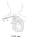
次に、図面(幾つかの図を通して、類似の参照番号は同様のまたは類似の部品を示す)を詳細に参照すると、本発明のカテーテル第一の実施例は、参照番号10で一般に示されている。カテーテル10は、充分な血液が透析のために身体から輸送され得ることを保証するために、典型的には高速血流領域に挿入される。図1は、右内部頚静脈「a」を通して上大静脈「b」および右心房「c」に挿入されたカテーテル10を示している。図2は、左内部頚静脈「d」を通して上大静脈「b」および右心房「c」に挿入されたカテーテル10を示している。右側または左側からの右心房への挿入は、透析機への必要な高速血流を提供する。なお、カテーテル本体(カテーテル管)11は充分に可撓性であり、示された解剖学的湾曲部に適合するように曲がることを可能にする。
【0028】
カテーテル10は、遠位端部分31、近位端部分33、および中間部分35を有するカテーテル本体またはカテーテル管11を有している。遠位部分31は、図示のように実質的に円錐形状のノーズ32で終端している。近位端部分33は、透析のための血液の戻しおよび抜取りを可能にするハブ12、即ち遷移部を含んでおり、ここでは、カテーテル管11内に形成されたルーメンが流入および流出ハブ16,18に夫々結合されている。従来の管クランプ17および19は、所望により、流入管および流出管16,18を通る血流を遮断する。ここで使用する「流入」および「流出」の用語は、患者の身体に関する血流の方向を意味し、「流入」は透析機から身体に供給される流れを意味するのに対して、「流出」は身体から抜取られて透析機に輸送される流れを意味する。
【0029】
図示するように、カテーテル10の中間部分は、皮下組織トンネル「t」を通って延びており、標的部位(例えば、右心房)に向って下方に湾曲している。このトンネル「t」は、数週間、更には数ヶ月に亘って、透析のための適正な場所にカテーテルを固定し、繊維状カフ36(図3)が組織の内殖(ingrowth)を可能にする。トンネル「t」の形成および該トンネルを通してのカテーテル10の挿入については、カテーテル挿入法の検討に関連して以下で述べる。
【0030】
カテーテルは、第二の切開部位で組織トンネル「t」から出るように示されているが、好ましくは、該組織トンネルは第二の部位に出口開口部を有しておらず、その代わり、針および拡張器が内部頚静脈「a」に最初にアクセスする同じ切開部を通して出されるであろう。これについては以下で更に詳述する。
透析機に対する血液の輸送のために、カテーテルチューブの中には一連のルーメンが形成されている。当該技術において周知のように、透析機は本質的に、腎不全に罹った患者のための腎臓として機能する。患者から血液が取出されて透析機に送られ、そこでは半透膜を通して透析液中に拡散することにより毒素が除去される。次いで、この濾過された血液は、カテーテル本体を通して患者に戻される。
【0031】
次に、図5、図6A、図7および図8を参照して、カテーテルルーメンを更に詳細に説明する。中央の長手方向ルーメン40が、カテーテル管11内に全長に亘って形成されており、これは濾過された血液を患者に輸送するように設計されている。また、ルーメン40は、カテーテルを所望の位置に向けるために、ガイドワイヤ20を収容するように構成されている。ルーメン40はノーズ42まで延びており、それがノーズ42の中央長手方向ルーメン41と整列する領域37で終端している。ノーズ42の中央ルーメン41は、患者の身体と連通する遠位開口部47で終端する狭いルーメン45と連通しており、従って、血液は遠位開口部47を通して送達されることができる。ルーメン41および45もまた、ガイドワイヤ20を収容する。従って、ルーメン40、ルーメン41および狭いルーメン45は一緒になって、透析機から患者への血液の送達を可能にする中央ルーメンを形成する。ルーメン41から狭いルーメン45への遷移部分は、停止部または肩部43を形成しているが、その機能については以下で説明する。
【0032】
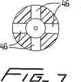
ノーズ42はまた、外壁44を貫通して形成された側部動脈(送達)開口部46を含んでおり、該開口部は、これもまた患者の身体へと血液を戻すように機能するルーメン41と液体流通している。側部の開口部またはポート46は、血流方向での血液の送達を容易にし且つ機械的溶血を少なくするために、好ましくは図示のように外側に傾斜している。これらの追加の開口部は、複数の孔に亘って血液を分布させることにより、所望の流れ容積を維持するのを補助する。四つの開口部だけが示されているが、追加の開口部、または、より少ない開口部を設けることができ、また、これら開口部は相互に対して軸方向に配置できることも想定される。また、追加の組の開口部は、側部開口部46から近位方向または遠位方向に離間して設けることもできる。
【0033】
この実施例において、ノーズ42は遠位チップ部分を形成しており、またカテーテル11の他の部分とは異なる材料で構成され、溶接または他の手段によってカテーテル本体11に取付けられる。この実施例における該チップ(ノーズ)は、組織を貫通するトンネル形成および鈍い切除を容易にするために、硬い材料で構成される。或いは、該ノーズを軟質材料で構成することにより、血管壁と接触したときに外傷が生じ難くすることもできるであろう。しかし、好ましい実施例においては、該ノーズはカテーテル本体と同じ材料で構成されると共に、その中に小さい補強部材が埋設される。この構成については、図13〜図15に関連して以下で詳細に説明する。
【0034】
カテーテル10はまた、カテーテル本体11の長さに沿って長手方向位に延びる一連の静脈(抜取り)ルーメン34a〜34eを有しており、その夫々はノーズ42の表面48で終端している。図8の断面図に示す好ましい実施例において、ルーメン34は楕円形状であり、対向する湾曲壁37a,37bおよび対向する実質的に平坦な壁39a,39bを有している。これらの離間したルーメンの間には固体材料が存在しており、これによりカテーテル本体11の構造的一体性が増大している。該ルーメン34a〜34eは、これらが共通のコネクタ管に接続されるハブ12までは、カテーテル本体11の遠位部分33、中間部分34および近位部分35を通して相互に独立している。これについては以下で更に詳述する。図示のように、ルーメン34a〜34eは、中央の動脈ルーメン40から放射状かつ対称的に配置されている。
【0035】
図5および図6Aを継続して参照すると、一連の側部開口部またはポート50が、カテーテル本体10の外壁に設けられている。これらの開口部50a,50b,50c,50dおよび50eは、夫々流出ルーメン34a〜34eと液体連通しており、透析機に供給するために患者の身体から血液を抜取るように設計および構成されている。開口部50a〜50eから近位方向に離間した第二の組の開口部52a〜52eもまた、夫々のルーメン34a〜34eと液体連通している。図5には三つの側部開口部50,52のみが示されているが、他の三つの開口部は、静脈ルーメン34a〜34eの円周方向の配置に適合するように、カテーテルの他の側に、好ましくは、対称に配置されるものと理解される。
ルーメン34a〜34eはカテーテルの実質的長さに沿って分離されているが、好ましくは、これらはカテーテル10の近位部分に共通の流れ起点を有している。これについては以下で更に詳述する。
【0036】
図8の実施例において、動脈ルーメンの断面積サイズは、好ましくは、約0.1524mm(約0.006インチ)〜約0.2032mm(約0.008インチ)であり、より好ましくは、約0.1778mm(0.007インチ)である。各静脈ルーメン34の断面積は、好ましくは、約0.0508mm(約0.002インチ)〜約0.1016mm(約0.004インチ)、より好ましくは、約0.0762mm(約0.003インチ)であり、静脈戻りルーメンの全断面積を約0.254mm(約0.01インチ)〜約0.508mm(約0.02インチ)、より好ましくは、約0.381mm(約0.015インチ)にするものである。これは、静脈ルーメンに対する動脈ルーメンの全断面積の比が、約1〜約2.1であることを意味する。他の寸法もまた想定される。
なお、5つの別々のルーメン34が示されているが、より少ない数のルーメンを設けてもよいし、または、より多い数のルーメンを設けてもよいことを理解すべきである。また、二組の側部開口(組50および組52)が示されているが、より少ない数の組を設けることもできるし、または、より多い数の組を設けることもでき、また夫々の組に、より少ない数の開口部を設けることもでき、または、より多い数の開口部を設けることもできるであろう。
【0037】
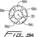
円周方向に離間された別のルーメン構成が、図9A、図9B、図9Cおよび図10に示されている。図9Bでは、三つの弧状のルーメン60a,60b,60cが動脈中央ルーメン40'の回りに配置されている。これらの大きな寸法のルーメンは追加の静脈流を与えるが、図8のルーメン構成に比較して壁材料が少ないために、カテーテル壁の強度減少をもたらす。図9Aにおいては、五つのルーメン66a,66b,66c,66d,66eが設けられる。これらのルーメンは、図8のルーメン構成よりもむしろ、矩形(または台形)の形状を有しており、一対の対向壁が直線的な構成を有している。図示するように、他方の対の対向壁は僅かに湾曲している。図9Cにおいては、四つの楕円状の静脈ルーメン76a,76b,76c,76dが、実質的に正方形の中央ルーメン78の回りに配置されている。このルーメンの構成は、かなりの大きさの中央ルーメン、および、カテーテル壁が曲がるために中央ルーメン78と、各静脈ルーメン76a〜76dとの間の充分な余裕を提供する。図10においては、円形断面の五つのルーメン70a〜70eが中央ルーメン40''の回りに設けられており、壁材料を増大させることによってカテーテルの安定性を高めるが、図8の実施例に比較して全体の静脈ルーメンの大きさを減少させる。好ましくは、これらの各実施例における静脈ルーメンは、カテーテルの実質的長さに沿って相互に独立している。
【0038】
より少ない数を設けることもできるし、または、より多い数のルーメンを設けることもできるであろうし、また他の構成のルーメンも想定される。カテーテルの回りでのこの円形アレイ状の静脈ルーメン配置、即ち、カテーテルの中心からの放射状の配置は、並置される静脈/動脈ルーメン構成に比較して減圧をより均一に分布させて、一定の帰還流を確実にする。何故なら、ルーメンの一つが血管壁に固着または詰まると、残りのルーメンが充分な流れを維持するからである。また、ルーメンと連通した側壁の開口部は円形でなく細長くてもよく、吸引された血液を導入するために、長手方向に延びる一連の開口部を形成することができる。この細長い開口部は、例えば以下で詳述する図18および図20に示されている。
【0039】
挿入を容易にするために、カテーテルは補強ロッドの形態の補強部材を収容するように構成され、該補強ロッドはカテーテルを伸長させてそのプロファイルを減少させ、ワイヤ上での挿入および小血管を通るより良好な操縦を補助する。即ち、ワイヤ上での挿入および小血管を通る操縦を容易にするために、該補強ロッドはカテーテル10の中央ルーメン40の中に挿入され、トルクを与えられて可撓性カテーテルを硬化させ、また挿入の際にそれを伸長させることによってカテーテル本体の外径を減少させる。カテーテル10が配置された後、この補強ロッドは除去されて、身体との間での血液の輸送のために必要な大きさのルーメンを持った高いプロファイルの位置に復帰することを可能にする。補強ロッドの二つの実施例が図4Aおよび図4Bに図示されており、図3のカテーテル10の中に挿入する前の状態で示されている。
【0040】
図4Aに示した補強ロッドの第一の実施例に戻ると、該補強ロッドは、参照番号80で示されている。補強ロッド80は、遠位チップ82、近位端部分85、および、中を通って延びる内部ルーメン87を有している(図11参照)。補強ロッド80は、流入管16の近位端を通して図11の矢印の方向に、中央ルーメン40を通り、図12に示すように肩部または停止部43に当接するまで、ガイドワイヤ20(ルーメン87を通る)上を挿入される。補強ロッド80の近位端部分85は、ねじ付き部分81を有しており、これは流入管16の螺合ねじ15に螺入される。これにより、補強ロッド80は挿入の際にカテーテル10内に一時的に固定される。このねじ装着は、補強ロッド80が肩部(当接表面)43を前方に押圧して力を加え、カテーテル本体11を伸長させてその外径を縮小するときに、ロッド80を手で捻ることにより該ロッド80にトルクを付与することを必要とする。一つの実施例では、例えば、補強ロッド80によって、カテーテル本体11が約0.215ミリメータから約0.207ミリメーターに直径を減少できることが想定される。(他の寸法減少もまた想定される)。このカテーテル本体の直径またはプロファイルの減少は、補強ロッド80によって行われる寸法変化を示す図11および図12の矢印D1およびD2によって表される。
【0041】
カテーテル10が所望の位置に配置された後、補強ロッドは流入管16の基端部ねじ15から外され、カテーテル本体10の中央ルーメン40および流入管16から除去され、それによってカテーテルが図11の正常なプロファイルに復帰するのを可能にする。
なお、変形例として、補強ロッド80はバヨネットロック、スナップ嵌合などのような他の手段によって、その基端部で流入管16に一時的に取付けできることが理解されるべきである。このロッドは最初に手で捻られ、次いでそのトルク付加された位置に保持するために、これら種々の手段によって装着できるであろう。
【0042】
補強ロッドの別の実施例が図4Bに示されており、参照番号90によって、全体的に表されている。補強ロッド90はねじを付した遠位端92を有しており、これは図6Bに示したカテーテル200の内部ねじ251上に螺合される。一連の近位ねじ91は、補強ロッド80について上述したのと同じ方法で、流入管16のねじ15上に螺合される。補強ロッド90は、補強ロッド80と同様に、即ち、挿入の際にカテーテルを伸長してそのプロファイルを減少し、且つそれを硬化させて挿入を容易にするように機能する。唯一の相違は、カテーテル10の肩部43との当接関係の代りに、補強ロッド90の遠位端をカテーテル200に機械的にねじ留めすることである。好ましくは、遠位ねじ92は最初に内部ねじ251に螺合され、続いて補強ロッドがトルク付与されるときに近位ねじ91が取付けられる。補強ロッド80と同様に、補強ロッド90は好ましくは断面が円形であるが、他の構成も想定される。
【0043】
図6Bのカテーテル200は、肩部43の代りのねじ251、および直径の均一なルーメン241を除き、全ての点でカテーテル10と同一である。カテーテル10と同様に、カテーテル200は、遠位チップ部分242のルーメン241と流通する遠位開口部247および外壁244の流出側部開口部246を有している。静脈流入ルーメン234a〜234eは、壁248で終端し、また外壁214に形成された夫々の側部開口252a〜252eおよび250a〜250eを有している。図6Bの縦断面図には、唯一の側部開口252a、250aだけが示されている。
【0044】
上記のように、遠位チップ(ノーズ)は、カテーテル本体11よりも硬い異なる材料で構成することができ、またはカテーテル本体よりも高いデュロメータ値を有する材料で構成することができる。この更に硬い材料は、組織のトンネル形成および拡張の両方を容易にするであろう。しかし、別の好ましい実施例においては、遠位チップはカテーテル本体と同じ材料で構成されるが、補強挿入物を有している。
【0045】
より詳細に言えば、別のノーズ(チップ)構成が図15に示されており、該チップを製造する方法が図13および図14に示されている。このノーズまたは遠位チップ104は、カテーテル本体108と同じ材料で構成されており、またノーズ104の中央ルーメン106を通して挿入された補強挿入物110を有している。中央ルーメン106はカテーテル本体を通して延びている。補強挿入物110は、カテーテル本体11の85ショアAに対して、72ショアDのようなより硬いデュロメータ値の材料で製造される点を除き、好ましくはカテーテル本体11およびノーズ104と同じ材料で構成される。利用される材料は、例えばウレタンであることができる。便宜上、遠位チップだけが示されているが、カテーテル100の残りの部分もカテーテル10と同じである。
【0046】
好ましくは図示のように円筒状の補強挿入物110は、ガイドワイヤを収容するため、および中央ルーメン106と連通するための孔112を有している。挿入物110は、中央ルーメン106の内壁表面114と係合する。ルーメン106、即ち、側部開口119の近位部分は、補強ロッド80のための当接表面(肩部)を提供する段差部分、または上記で述べた補強ロッド90を装着するための内部ねじを含んでいる。
【0047】
次に、図13〜図15に関連して、この弾丸形状のノーズ104を製造する方法を説明する。好ましくは、射出成形技術により、中央動脈ルーメン106および静脈ルーメン109a〜109eを備えた円筒管が形成されたら、最遠位端において円筒管の最遠位縁102と実質的に同一平面になるように、補強挿入物110を中央ルーメン106内に配置する。
【0048】
補強挿入物またはスラグ110が中央ルーメン106内に配置されたら、この管は、チップ材料を流動させて更に硬い挿入物110の回りに形成することを可能にする従来の高周波加熱または他の加熱プロセスによって、図15Aおよび図15Bの弾丸ノーズ形状に成形される。該材料は挿入物110に融合するので、ダイの加熱およびこの構成への形成の後に、該材料は冷却されることにより図15の形状に硬化される。この成形プロセスの際に、従来のコアピン(図示せず)を使用し、孔112および中央ルーメン106を通して挿入することができる。材料が硬化したとき、このピンを抜取ってこれら開口部を維持する。成形プロセスの後に、図1〜図6の中央ルーメン40と連通する側部穴46と同様にして、ルーメン106と連通するように、カテーテル100の壁108を貫通する側部孔114が切出され、または穿孔される。
【0049】
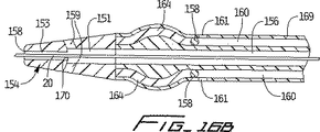
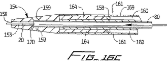
図16A〜図17Cは、カテーテル本体の血管壁との接触を最小限にするスペーサをもった、本発明のカテーテルの二つの別の実施例を示している。これらスペーサを提供することは任意である。図16A〜図16Cの実施例において、カテーテル150はカテーテル10と同様に、ノーズ154、ガイドワイヤ20も収容する中央動脈ルーメン156、および一連の(例えば五つ)静脈ルーメン160〜160を有する遠位部分を有している。動脈ルーメン156は、ルーメン151、および開放遠位端158で終端するノーズ154の狭いルーメン153と連通している。複数の側部開口部159はルーメン151と連通しており、またカテーテル10の側部開口部46と同様にして機能する。カテーテル10における静脈ルーメン34の側部開口部52と同様に、静脈ルーメン160は、側部開口部161でそれぞれ終端している。一連の側部開口部161が一つだけ示されているが、側部開口部161の遠位側または近位側に配置された、追加の側部開口部アレイを設けてもよいことが明らかであろう。静脈ルーメン構成もまた、カテーテル10に関して上述したのと同様の方法で変化することができる。従って、スペーサを別にすれば、カテーテル150はカテーテル10と同一である。
【0050】
複数のスペーサワイヤ164がカテーテル150の壁169の中に埋設されており、接着剤または他の適切な手段によって領域158に固定されている。正常な構成において、スペーサワイヤ164は、血管壁と接触する可能性を低減するように、カテーテル150の外壁169に対して僅かに外側に曲がっている。補強ロッド80がガイドワイヤ20上を中央ルーメン156を通して挿入され、また図16Cに示すように、エッジ170が当接表面または停止部材159に押しつけられるときは、カテーテル本体が真直ぐな位置に伸張されて、スペーサワイヤ164は壁169の外表面と実質的に同レベルになる。これはカテーテルのプロファイルを減少させて、スペーサワイヤがカテーテルの挿入を妨害しないことを保証する。補強ロッド80が抜取られると、カテーテルはその正常な位置に復帰し、スペーサワイヤ164は図16Aおよび図16Bに示すように外側に湾曲する。なお、補強ロッド90はカテーテル150と共に使用することができ、ロッド80と同じ方法でプロファイルを減少するように機能することを理解すべきである。次に、カテーテル150には補強ロッドを装着するための内部ねじが設けられるであろう。
【0051】
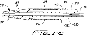
スペーサワイヤの別の例が図17A〜図17Cに示されている。カテーテル180は、ノーズ184の近位側に一体のリブ194が設けられている点を除き、カテーテル150と同一である。即ち、カテーテル150と同様に、カテーテル180はガイドワイヤ20および補強ロッド80または90を収容するように構成された中央ルーメン186を有している。該ルーメン186は、ルーメン181および開放遠位端188で終端するノーズの狭いルーメン183と連通する。ノーズ184の側部開口部189はルーメン181と連通する。一連の独立した静脈ルーメン190が設けられており、これらはカテーテル150の側部開口部と同様、側部開口192の中で終端している。一連の側部開口部192が一つだけ示されているが、側部開口部192の近位側または遠位側に配置された、追加のアレイを設けてもよいことは明らかであろう。
【0052】
カテーテル150の壁193における切欠によって、スペーサリブ194が形成される。図17Bは、カテーテル本体の壁193の外表面から外側に湾曲した、それらの正常位置にあるスペーサリブ194を示している。図17Cは、図4Aの補強ロッド80(または図4Bの補強ロッド90)が中央ルーメン186を通して挿入され、上記のようにして挿入のためにカテーテル150が伸長された後の、真直ぐの位置または後退位置にあるスペーサリブ194を示しており、この場合は該リブ194が壁193の外表面と実質的に同一レベルにある。
【0053】
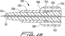
図18および図19は、本発明のカテーテルのもう一つ別の実施例を示している。カテーテル500は、直径が小さい領域504へと遷移するテーパ領域510を備えた遠位チップ502を有している。中央ルーメンは、液体供給のための遠位開口部506において終端している。先に述べた実施例とは異なり、遠位開口部506は、身体の中への唯一の液体送給通路である。しかし、患者への血液送給のための追加の動脈ポートを提供するために、チップに追加の側部孔を与えてもよいことが想定される。
【0054】
一連の静脈開口部508(図18には二つだけが示されている)が、チップ502の遷移領域またはテーパ領域に設けられる。これらの開口部は、吸引のための追加の領域を提供するために細長くなっている。夫々の開口部508は、カテーテルに形成された夫々の静脈ルーメン510と連通している。静脈ルーメンの構成(および動脈ルーメンの構成)は、図7〜図10に示された形態であることができ、または上記で説明した他の変形であってもよい。
【0055】
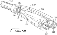
補強ロッド520は、カテーテル500の中央ルーメンに配置された状態で示されている。ロッド520は、それがカテーテル500の遠位チップ502から遠位方向に延び、組織をトンネリングおよび拡張するのを容易にするようにテーパした遠位端524を有し、またカテーテルの内部構造に当接するテーパした部分を有している点を除き、上記で説明したロッド80および90と同様である。更に詳細に言えば、ガイドワイヤ20は、補強ロッド520の中央ルーメンを通って延びるように示されている。補強ロッド520はカテーテル500の中央ルーメンを通して挿入され、該補強ロッド520およびカテーテル500はガイドワイヤ20上を挿入されるが、その際、テーパしたチップ524は組織を拡張させるので、カテーテルの通過を容易にする。
【0056】
カテーテル500は、図13Aの挿入物110と同様の、遠位チップに位置する円筒形挿入物514を有する。該挿入物514は、カテーテル500のチップを硬化させて挿入を容易にするために、硬質の材料で構成される。挿入物510は、図示のように補強ロッド520を収容する開口部を有している。段差部分524により形成される肩部526は、挿入物514に当接することにより、図11に示した肩部43が補強ロッド80の停止部材として作用したのと同様にして、停止部材として機能する。両者の相違は、該肩部が補強ロッド上にではなく、カテーテルの内部壁に形成されることである。従って、補強ロッド520は、上記ロッド80,90のようにして働く。即ち、組織のトンネリングおよび拡張機能を提供することに加え、カテーテルチップ部分を押圧して、カテーテルを挿入のために伸長させる。
【0057】
図20は、本発明によるカテーテルの別のチップ設計を示している。カテーテルチップ602は、より漸進的なテーパを有する点を除き、図15のノーズに幾分類似した弾丸ノーズの構成を有している。カテーテルチップ602はまた、一連の細長い静脈孔608(図20にはその二つだけが示されている)を有している。他の全ての点において、カテーテル600は図18のカテーテル500と同じである。
【0058】
本発明のカテーテルの挿入方法は、全てワイヤ上で行われるシステムを提供する。これは、図22および図23に示した套管針を提供することによって達成される。套管針300は、ガイドワイヤ20を収容する寸法で、それを貫通して形成されたルーメン304(図22では想像線で示される)を有している。該ルーメン304は、ハンドル308における近位開口306から、図22で見たときに套管針300の下面にある遠位開口部310(図22では想像線で示される)まで、套管針300の全長に亘って延びている。遠位開口部310は、遠位チップが僅かに上方に湾曲する領域において、遠位チップ302に隣接している。なお、套管針300のルーメン304は、ガイドワイヤを収容するために約1.143mm(約0.045インチ)の内径を有することだけを必要とするから、透析カテーテル、例えばカテーテル10の外径より小さくてもよい。カテーテルの外径は、典型的には、約5.461mm(0.215インチ)である。套管針300の鈍い遠位チップ302は組織を切除して、後でカテーテルを皮下固定するための皮下組織トンネルを形成する。
【0059】
図24Aおよび24Bは、套管針の別の実施例を示している。套管針380は、ガイドワイヤ用ルーメン383への細長い楕円形の入口開口部382、および組織を貫通するトンネリングを容易にする傾斜チップ384を除いて、套管針300と同様である。また、ハンドルの構成386も僅かに異なるだけである。
次に、該カテーテルを使用する一つの方法を、図25〜図28に関連して説明する。カテーテル10の挿入についてこの方法は説明するが、上記で述べた如何なるカテーテルも同様にして挿入できることが理解されるべきである。
先ず、針「N」を内部頚静脈に挿入して血管を適正に突き止め、この針を通して、ガイドワイヤが右内部頚静脈「a」の中に挿入され、また図25に示すように上大静脈「b」の中に挿入される。ガイドワイヤ20を、右心房「c」の中に更に前進させる。次いで、針「N」を抜取ってガイドワイヤをその場に残し、近位部分21を患者の体から外へと延ばす。
【0060】
次に、套管針300を第一の切開部「s」を通して患者の中に挿入し、皮膚の下を切開およびトンネリングさせて、第二の切開部または部位「u」において組織から引き出し、図27に示すように組織の下の皮下トンネル「t」を形成する。以下で述べるように、これはカテーテルを固定する方法を提供する。次いで、先ずガイドワイヤの近位部分21を套管針の遠位開口部310に挿入し、図28Aに示すようにそれが近位開口部306から出るようにして、ガイドワイヤ20を套管針304のルーメンの中に通す。次いで、套管針300を図28Bの矢印方向に身体から抜取り、図示のようにガイドワイヤをその場に残す。こうして、ガイドワイヤ20は右心房および上大静脈から右内部頚静脈および組織トンネル「t」を通して延ばされる。
【0061】
次いで、ガイドワイヤ20上にカテーテル10が通されるが、その際に、ガイドワイヤ21の近位部分21がカテーテルの遠位チップを通され、中央ルーメンの全長を通され、またハブ12を通して流入管116の中に挿入され、治具15を通して出される。こうして、カテーテル10はワイヤ上を組織トンネル「t」を通されるが、ここでは、長期間に亘って組織の内殖を可能にすることによりカテーテルの固定を補助するために、カフ36(図28Cには図示されていない)が組織トンネル「t」に配置される。カテーテル10は更にガイドワイヤ上を前進して、右内部頚静脈の中を下降し、上大動脈および右心房の中へと進められる。ガイドワイヤ20は矢印の方向に抜取られ、図28Cに示すように、カテーテルを使用のためにその場に残す。なお、好ましくは、補強部材80または90(図28Cには明瞭に示されていない)が利用される。即ち、ガイドワイヤ20上を治具15、流入管16、ハブ12、および中央ルーメン40を通されて、上記で詳述した様にしてカテーテル10の案内を補助する。
【0062】
理解できるように、カテーテルは、図2に示したようにして、同様の方法で左内部頚静脈を通して配置されるであろう。この方法では、皮下組織トンネルは、図2に示すように套管針300によって左側に形成され、カテーテルはガイドワイヤ上を皮下組織トンネルを通り、右側切開について説明したのと同じ方法で、左内部頚静脈および上大静脈を通して右心房に挿入されるであろう。なお、本発明の上記カテーテルは何れも、この方法で挿入できることが理解されるべきである。
【0063】
別の方法が図29A〜図29Gに示されている。この方法では、図27に示したような、針およびガイドワイヤを内部頚静脈の中に導入する切開部に隣接した第二の切開部を形成する代りに、套管針300が針/ガイドワイヤ挿入部位から出される。カテーテル10が示されているが、先の何れのカテーテルも同じ方法で挿入することができる。
【0064】
この方法において、針およびガイドワイヤは、図25および図26に示したのと同じ方法で挿入される。針を除去した後のガイドワイヤは、「w」で示すように、切開部から外側に延びた状態で残される。次に、図29Aに示すように、皮下組織トンネルを形成するために套管針300が第一の切開部(図27におけると同様に)を通して挿入される。しかし、図27とは異なり、套管針は第二の切開部「u」において出てこない。その代りに、套管針300は針切開部「w」まで皮下を前進して、図示の部位「w」を通して出現する。従って、図29Aに示すように、套管針300'の遠位端はガイドワイヤ20に沿って切開部「w」を出る。
【0065】
次に、上記で述べたように、ガイドワイヤ20が套管針の開口部を通して挿入され、次いで套管針が組織トンネル「t」を通して引抜かれ、第一の切開部「s」を通して出され、ガイドワイヤ20がトンネルを通して引張られる。ガイドワイヤ21がトンネル「t」を通して引張られ、切開部「s」を通して外に出された後に、套管針は除去されて、ガイドワイヤがその場に残される。なお、以下で説明するように、ガイドワイヤ20は、カテーテルの挿入を容易にするためのガイドワイヤループ22を形成するように配置される。
【0066】
次いで、カテーテル10はガイドワイヤ20上を前進され(図29C)、組織トンネルを通り、切開部「w」を出て内部頚静脈「a」のへと進められる(図29D)。図示のように、カテーテル10はループ13に形成され、ガイドワイヤ20のループ20に追従し、次いで内部頚静脈を通って下降し、上大静脈を通って右心房の中に進められる(図29E)。次いで、ガイドワイヤ20を引抜き、カテーテル10を下方に押し下げ、および/または、引き戻してループを直線化し、図29Fに示すようにカテーテルを配置する。
なお、ガイドワイヤおよびカテーテルのループ形成は任意であり、この処置はループ無しで行うことができることを理解すべきである。
【0067】
図30は、糸を回収し、またそれを皮下組織トンネルを通して後退させるために利用される套管針の別の実施例を示している。套管針300'は、はと目孔312が設けられている点を除き、図29の套管針300と同様である。当該糸は、このはと目孔に通され、套管針が組織トンネルを通して近位方向に引張られ、切開部「s」を通して糸が引き出される。図示のように、套管針は切開部「w」、即ち、針およびガイドワイヤの挿入のために形成された同じ切開部を通って延びる。
はと目孔の代りに、組織トンネルを通してガイドワイヤを引張ることを可能にするための、ガイドワイヤを保持する鉤または他の手段を套管針に設けてもよいことが理解されるべきである。即ち、これらの変形例において、ガイドワイヤは套管針のルーメンに通されることなく、套管針は組織トンネルを通してガイドワイヤを引張る(後退させる)ために利用される。
【0068】
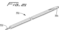
図21は、カテーテル挿入のための異なるアプローチに使用される別の套管針を示している。参照番号350で示すこの套管針は、全てワイヤ上でのシステムを提供しないが、引裂き導入体鞘の必要性を排除する部分的にワイヤ上でのシステムを提供するアプローチと共に使用される。本出願明細書の背景の節で述べたように、引裂き導入器鞘は、血管を通して透析カテーテルを右心房に案内するために現在利用されている。この引裂き鞘に付随する問題を回避するために、この別法におけるカテーテルは、図25〜図26に示した方法で配置できるガイドワイヤ上を前進させることができる。
この方法において、套管針350は、矢尻を設けた端部352を嵌合治具の中に挿入することによって、カテーテルの遠位端に結合される。套管針を一時的に取付ける他の手段も想定される。
【0069】
套管針350は鈍い遠位チップ354を有しており、第一の組織切開部を通して進められ、組織を鈍く切除して、ガイドワイヤを用いない以外は上記で述べたのと同様の方法で皮下組織トンネルを形成する。套管針350はカテーテルに結合されるので、それは組織トンネルを通してカテーテルを引張り、該カテーテルは第二の切開部を通して出現する。次いで、套管針350はカテーテルから取外される。次いで、カテーテルは必要に応じて曲げられ、ガイドワイヤ上を頚静脈、上大静脈、および右心房の中に通される。
【0070】
次に、特に図31〜図37を参照して、カテーテルのハブを製造する一つの方法を見てみると、カテーテルの中央動脈(送達)ルーメンの流入管との接続と、五つの独立した静脈(抜取り)ルーメンの単一の流出管との接続を可能にして、コネクタを通しての液体流通を提供するする方法が開示されている。
【0071】
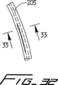
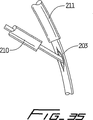
最初に図31を参照すると、カテーテル管203の近位部分に、長手方向のスリット201が形成される。図32は、スリットが形成されて中央ルーメン205と連通するときの、該スリット201と中央動脈ルーメン205との関係を示している。図33の断面図から理解できるように、スリット201は、隣接する静脈(抜取り)ルーメン209a〜209eの間でカテーテル管203の壁に形成される。次に、モールドプロセスのために、金属ピン207がスリット201を通して挿入される。外側プラスチック性流入管210が、図35に示すように金属ピン207を覆って配置され、最終的には中央ルーメン205と連通される。また、カテーテル管203を覆って配置された、静脈ルーメン209と連通する外側プラスチック流出管211も示されている。
【0072】
次に、従来の射出成形技術を利用して、図36に示すように、カテーテル管203および金属ピン207の回りに軟質プラスチック材料が流される。次いで、該材料を冷却および硬化させてハブ208を形成し、金属ピン207を除去してルーメン204を形成する。ルーメン204は狭くなった領域202を有する。図37に示すように、ルーメン204は、流入管210のルーメン207をカテーテルの中央ルーメン205と液体連通させる。流出配管211のルーメン212は、五つの独立した静脈ルーメン209と連通する。
【0073】
図38〜図39は、カテーテル連結を製造するためのもう一つの方法を示している。この方法において、カテーテル400のカテーテル本体402は、その最近位端において、静脈(抜取り)ルーメン403a〜403eの夫々に対応する五つの切片401a〜401eに分離される。図40は、五つの切片401を形成するために、隣接する静脈ルーメン403の間のカテーテル壁407に作製された五つの切り込み408を示している。
別々の流出コネクタ管412a〜412eは、夫々の静脈ルーメン403a〜403e内に配置され、また溶剤接合または加圧嵌合によって夫々の切片401aから401eに接続される。各コネクタ管412の近位端は、血液を透析機に輸送する流出管414内に配置される。こうして、血液は静脈ルーメン403を通り、また各流出コネクタ管401を通って、単一の流出管414の中に流れる。
【0074】
流入配管416は、溶剤接合または加圧嵌合により動脈ルーメンの内側に結合される流入コネクタ管410によって、中央動脈ルーメンに接続される。なお、流入コネクタ管410は、切片401の間に配置される。より少ない数またはより多い数の静脈ルーメンを設けるときは、静脈ルーメンと等しい数の流出管が利用され、対応する数の切片に切断されることが理解されるべきである。
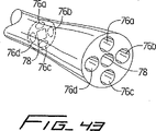
図41〜図43は、本発明のカテーテルのハブを製造するための、もう一つ別の方法を示している。このハブおよび付随する配管は、図9Cのルーメンの構成を有するカテーテルと共に使用するために示されているが、同様に、他のルーメン構成と共に利用することもできる。
【0075】
中央ルーメンコネクタ(中間)管702が、カテーテル700の中央ルーメン78と連結される。四つの静脈連結(中間)管704が、夫々の静脈ルーメン76aに接続される。これら夫々の管は、その長さに沿って、断面が実質的に円形のルーメンを有している。この実質的に円形のルーメンは、カテーテル10内の静脈ルーメンの断面形状に対応しており、これらは図43に示す拡開した近位部分において、実質的に楕円の断面形状から実質的に円形の断面形状に変化する。なお、動脈ルーメン78もまた、実質的に円形の断面形状に変化する。
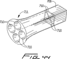
コネクタ管704の夫々は、血液の透析機への流出を与える多重ルーメン延長(流出)管708に接続される。延長管708は、四つのルーメン710を備えた拡開した遠位部分711を有しており、その各ルーメンは、コネクタ管704の一つと連通する様に構成されている。図示のように、夫々のルーメン710は実質的に円形の断面形状を有しており、これは近位部分に向かって実質的に三角形の断面形状に変化する。
【0076】
患者への血液の流入を与える単一のルーメン延長(流入)管712が、コネクタ管702に接続している。延長管712は、テーパした遠位端718を有しており、そのルーメン719は、近位端に向って、実質的に円形の断面形状から実質的に正方形の形状に変化する。いる。ハウジング716を先の管と共にモールド成形することにより、カテーテルハブが形成される。図1のクランプ17および19のような従来の管クランプが、血流を遮断するために、延長管708,712の回りに配置される。
回転可能な糸リング720は、カテーテルハブの回りに配置され、また、好ましくは患者の皮膚と実質的に同一平面に着座するように平坦な表面を有する。糸通し孔724は、リング(従ってカテーテルも)を患者に取り付けるための糸を収容するように構成される。
【0077】
上記で述べたカテーテルは、任意に、外部および/または内部の表面処理を含むことができる。この表面処理は、例えば、潤滑性を増大して挿入を容易にする親水性コーティング、ヘパリンまたはIIb,IIIa阻害剤を含有する薬物コーティング、Sorins炭素コーティングのような不活性コーティング、および/または銀イオンコーティングのような活性コーティングを含むことができる。
なお、ここではカテーテルを血液透析のための透析カテーテルとして説明したが、ここに開示したカテーテルは、薬物デリバリーまたは血液サンプリングのような他の外科的用途をも有し得ることが理解されるべきである。更に、当該カテーテルの特徴、チップ構成およびルーメン構成は、他のカテーテルにも利用することができる。
【0078】
上記の説明は多くの特定を含んでいるが、これらの特定は本開示の範囲に対する限定として解釈されるべきではなく、その好ましい実施例の単なる例示として解釈されるべきである。当業者は、特許請求の範囲によって定義される開示の範囲および精神内にある他の多くの可能な変形を想定できるであろう。
【図面の簡単な説明】
【図1】 図1は、患者の身体の右内部頚静脈および上大静脈を通して右心房内に挿入されている、本発明の多重ルーメンカテーテルの第一の実施例を示す平面図である。
【図2】 図2は、左内部頚静脈および上大静脈を通して右心房の中に挿入されている、図1の多重ルーメンカテーテルを示す平面図である。
【図3】 図3は、本発明の多重ルーメンカテーテルの第一の実施例の等角図であり、補強ロッドの挿入方向を示している。
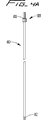
【図4A】 図4Aは、カテーテルの挿入を容易にするために図3のカテーテルを通して挿入可能な、本発明の補強ロッドの第一の実施例を示す側面図である。
【図4B】 図4Bは、その遠位端に一連の装着ねじを有する本発明の補強ロッドの別の実施例を示す側面図である。
【図5】 図5は、図3の多重ルーメンカテーテルの遠位部分を示す斜視図であり、中央ルーメンを通して延びるガイドワイヤを示している。
【図6A】 図6Aは、図5の線6A−6Aに沿った縦断面図である。
【図6B】 図6Bは、図4Bの補強ロッドを固定するための内部ねじを有するカテーテルの別の実施例を示している点を除き、図6Aと同様の縦断面図である。
【図7】 図7は、図6Aの線7−7に沿った横断面図である。
【図8】 図8は、図6Aの線8−8に沿った横断面図である。
【図9A】 図9Aは、本発明のカテーテルにおけるルーメン構成の第二の実施例を示している点を除き、図8と同様の横断面図である。
【図9B】 図9Bは、本発明のカテーテルにおけるルーメン構成の第三の実施例を示している点を除き、図8と同様の横断面図である。
【図9C】 図9Cは、本発明のカテーテルにおけるルーメン構成の第四の実施例を示している点を除き、図8と同様の横断面図である。
【図10】 図10は、本発明のカテーテルにおけるルーメン構成の第五の実施例を示している点を除き、図8と同様の横断面図である。
【図11】 図11は、図3のカテーテルにおける遠位端の縦断面図であり、該カテーテルの中央ルーメンを通して挿入されている図4Aの補強ロッドを示している。
【図12】 図12は、先端における停止部材に当接して、中央ルーメン内に完全に配置された補強ロッドを示している点を除き、図11と同様の縦断面図である。
【図13A】 図13〜図15は、本発明のカテーテルにおける先端チップおよび該チップを形成する方法工程の別の実施例を示している。図13Aは、図示の補強挿入物を受入れる前の形成前のチップを示す斜視図である。
【図13B】 図13Bは、図示の補強挿入物を受入れる前の形成前のチップを示す断面図である。
【図14A】 図14Aは、補強挿入物がその中に配置されたときのチップの斜視図である。
【図14B】 図14Bは、補強挿入物がその中に配置されたときのチップの断面図である。
【図15A】 図15Aは、弾丸ノーズ状の構成に形成された先端チップの斜視図であり、その中に形成された側部孔を示している。
【図15B】 図15Bは、弾丸ノーズ状の構成に形成された先端チップの断面図であり、その中に形成された側部孔を示している。
【図16A】 図16Aは、一連のスペーサワイヤを有する本発明の多重ルーメンカテーテルの、もう一つ別の実施例における先端部分の斜視図であり、その中を通って延びるガイドワイヤを示している。
【図16B】 図16Bは、図16Aのカテーテル先端部の縦断面図であり、伸長した位置にあるスペーサワイヤを示している。
【図16C】 図16Cは、ガイドワイヤ上を図4Aの補強ロッドが中央ルーメンの中に挿入され、挿入の際にカテーテルが伸長されるときの、スペーサワイヤおよびカテーテル本体の減少したプロファイルを示す以外は、図16Aと同様の縦断面図である。
【図17A】 図17Aは、一体的な一連のスペーサリブを有する本発明のカテーテルのもう一つ別の実施例における遠位部分を示す斜視図である。
【図17B】 図17Bは、図17のカテーテルにおける遠位部分の縦断面図であり、伸長位置にあるスペーサリブを示している。
【図17C】 図17Cは、図4Aの補強ロッドが中央ルーメン内に挿入され、挿入の際にカテーテルが伸長されるときの、スペーサリブおよびカテーテルの減少したプロファイルを示す以外は、図17Aと同様の縦断面図である。
【図18】 図18は、テーパしたチップを有する本発明の多重ルーメンカテーテルのもう一つ別の実施例における遠位部分を示す斜視図である。
【図19】 図19は、図18のカテーテルにおける遠位部分の斜視図であり、ガイドワイヤ上をカテーテルの中央ルーメンに貫通して配置された補強ロッドを示している。
【図20】 図20は、本発明による多重ルーメンカテーテルの更にもう一つの別の実施例における遠位部分の斜視図である。
【図21】 図21は、皮下組織トンネルを形成し且つ該組織トンネルを通してカテーテルを引張るために、カテーテルに取付けるための矢尻を付した遠位端を有する本発明による套管針の第一の実施例を示す斜視図である。
【図22】 図22は、ガイドワイヤを収容するためのルーメンを有する、本発明の套管針の別の実施例を示している。
【図23】 図23は、皮下組織トンネルが形成された後に引抜かれている、図22の套管針を示している。
【図24A】 図24Aは、ガイドワイヤを収容するためのルーメンを有する本発明による套管針のもう一つ別の実施例の底面図である。
【図24B】 図24Bは、図24Aの套管針における遠位端の縦端面図である。
【図25】 図25〜図28は、図3の多重ルーメンカテーテルを右内部頚静脈および上大静脈を通して右心房に挿入する外科的方法工程を示している。ここで図25は、右頚静脈を通して挿入されている導入針、および右頚静脈を通して挿入されているガイドワイヤを示しており、これらは上大静脈を通して右心房の中に挿入される。
【図26】 図26は、導入針を除去した後に、ガイドワイヤを右頚静脈、大静脈および右心房の中に残されたガイドワイヤを図示している。
【図27】 図27は、導入針用の切開部位に隣接した皮下組織トンネルを形成するように、第一の切開部位を通して挿入され、且つ第二の切開部位を通して延びる図22の套管針を示している。
【図28A】 図28Aは、図22の套管針のルーメンに通されたガイドワイヤを図示している。
【図28B】 図28Bは、組織トンネルを通って延びるガイドワイヤをその場に残して、除去された套管針を図示している。
【図28C】 図28Cは、ガイドワイヤ上で組織トンネルを通して挿入され、且つ下方に湾曲されて右内部頚静脈、大静脈および右心房の中に導入された、図3の多重ルーメンカテーテルを示している。
【図29A】 図29A〜図29Gは、図3の多重ルーメンカテーテルを、右頚静脈および上大静脈を通して右心房の中に挿入する別の方法の工程を図示しており、ここでは套管針が、針およびガイドワイヤが導入される切開部位に出口開口部を備えた組織トンネルを形成する。図29Aは、ガイドワイヤ上で第一の切開部位を通して挿入され、皮下組織トンネルを形成して、導入された針およびガイドワイヤの挿入のために形成された切開部位を出る図22の套管針を示している。
【図29B】 図29Bは、組織トンネルを通して延び且つ切開部に隣接したループを形成するガイドワイヤをその場に残して、除去された套管針を示している。
【図29C】 図29Cは、組織トンネルを通過するためにガイドワイヤ上を挿入される図3の多重ルーメンカテーテルを示している。
【図29D】 図29Dは、皮下組織トンネルを通して挿入されたカテーテルと、ガイドワイヤに形成されたループに対応したループの形成を示している。
【図29E】 図29Eは、皮下組織トンネルを通して延び、更にガイドワイヤに沿って右頚静脈の中に挿入されるカテーテルを示している。
【図29F】 図29Fは、除去されているガイドワイヤを示すことを除き、図29Eと同様の図である。
【図29G】 図29Gは、適所において皮下組織トンネルを通って延び、右頚静脈、上大静脈および右心房の中へと進められるカテーテルを示している。
【図30】 図30は、套管針によって形成された皮下組織トンネルを通して、ガイドワイヤを後退させる別の方法を示している。
【図31】 図31〜図37は、図3の多重ルーメンカテーテルにおけるハブの第一の実施例を製造する方法を示しており、図31は、カテーテルの外壁に形成されたスリットを示している。
【図32】 図32は、カテーテルの中央動脈ルーメンを仮想線で示すことを除き、図31と同様の図である。
【図33】 図33は、図32の線33−33に沿った横断面図である。
【図34】 図34は、カテーテル外壁のスリットを通して挿入されたピンを示している。
【図35】 図35は、ピンを覆って挿入された管を示している。
【図36】 図36は、ルーメンコネクタ管を適正位置に保持するカテーテルハブを形成するための、ピンおよびカテーテル管を覆うの軟質材料の注入を示している。
【図37】 図37は、一つのコネクタを流入(動脈)ルーメンと連通させ、他のコネクタを複数の流出(静脈)ルーメンと連通させることを可能にする、射出成形プロセスから得られるハブを示している。
【図38】 図38〜図40は、図3の多重ルーメンカテーテルにおけるハブの別の実施例を示している。ここで図38は、別々のコネクタ管を収容するように五つのセグメントに分割されたカテーテル本体の近位端を示す斜視図である。
【図39】 図39は、カテーテル本体の夫々のルーメンに挿入されたコネクタ管を示す斜視図である。
【図40】 図40は、分離されたセグメントを形成するためにカテーテル壁に造られた切り込みを示す横断面図である。
【図41】 図41は、図9Cのルーメン構成を有する、本発明のカテーテルにおけるハブのもう一つ別の実施例を示す斜視図である。
【図42】 図42は、図41のハブおよび管構造の分解図である。
【図43】 図43は、カテーテルの拡開した近位部分における、実質的な楕円から実質的な円構造への静脈孔の変化を示す拡大斜視図である。
【図44】 図44は、近位方向に向ってテーパし且つ実質的に円形の静脈孔から実質的に三角形の孔へと変化する、多重ルーメン延長部を示す拡大斜視図である。[0001]
BACKGROUND OF THE INVENTION
This application claims the priority of provisional patent application 60 / 260,592 filed on January 9, 2001, the entirety of which is incorporated herein by reference.
[0002]
<Technical field>
This application relates to catheters, and more particularly to multi-lumen catheters that facilitate hemodialysis.
<Background of related technology>
Hemodialysis is a well-known method of providing renal function by circulating blood extracorporeally. The kidney is an organ with a filtration unit called nephron that functions to extract water and urea, mineral salts, toxins and other waste products from the blood. From the nephron, the recovered waste is sent to the bladder for excretion. Because hemodialysis provides a machine that simulates the function of the kidneys, it saves the lives of patients who are defective in one or both nephrons.
[0003]
In hemodialysis, blood is drawn from the patient's body through a catheter or tube and transported to a dialysis machine, also called an artificial kidney. This catheter is typically inserted through the jugular vein and is steered to the right atrium through the superior vena cava to provide high velocity blood flow. In dialyzers, toxins and other waste products diffuse through the semipermeable membrane into the dialysate, which is closely matched to the chemical composition of the blood. The filtered blood, ie, blood from which waste has been removed, is then returned to the patient's body. In some instances, the catheter may be left in place for several years. As can be appreciated, proper access to the patient's blood and the transport of blood to and from the dialyzer over time is critical to hemodialysis.
[0004]
One example of a dialysis catheter currently on the market is the MedComp Ash Sprit catheter. This catheter has two lumens, one for arterial flow and the other for venous flow, each of which has a D-shaped cross section. The catheter is bifurcated at its distal end to separate the lumen, and the catheter is manually divided to the desired length for the selected separation before being inserted into the target area. The Another known catheter is the MedComp catheter, which has a venous flow lumen that terminates proximally (ie, axially retracted) from the arterial flow lumen. Each of these lumens has a D-shaped cross section.
[0005]
These Medcomp dialysis catheters (Medcomp dialysis catheters) require many steps for insertion. The multiple insertion steps are summarized as follows.
1. In order to properly locate (access) a blood vessel, such as the internal right jugular vein, a vascular needle is inserted through the first incision site.
2. Through the needle, a guide wire is inserted into the internal jugular vein, then descended down the superior vena cava and inserted into the inferior vena cava.
3. Pull out the introduction needle and leave the guide wire in place.
4). The sheath is torn (stripped) and a dilator is inserted over the guide wire through the first incision to provide a dialysis catheter access port into the jugular vein, superior vena cava and right atrium.
5. A second incision is made in the chest wall to form a second opening.
6). A trocar is attached to the distal end of the dialysis catheter.
7). The trocar and dialysis catheter are pushed through and advanced through the second incision to bluntly cut the subcutaneous tissue and out of the first incision formed by the introducer needle, thereby causing the first opening and the second A subcutaneous tissue tunnel is formed between the two openings.
8). The trocar is removed from the dialysis catheter, leaving the catheter in place and exiting from the first opening through the tissue tunnel from the second opening.
9. The dilator and guidewire are removed, and the teared and removed sheath is left in place at the first incision enlarged by the dilator.
10. A dialysis catheter protruding from the first incision is inserted and advanced through the torn sheath and its distal portion is placed in the right atrium.
11. The catheter is left in place by separating or splitting the sheath by pulling the tab away and then pulling it down from the dialysis catheter and removing it from the body.
12 The second incision is closed and the dialysis catheter connected to the dialysis machine through a tube is left in place for a long time to provide circulation to and from the dialysis machine.
(Alternatively, in the method described above, the trocar can be removed through a third incision adjacent to the first incision and then inserted through the introducer sheath).
[0006]
This multi-step process of inserting a Medcomp dialysis catheter is time consuming and complicates the surgical procedure. These multi-step methods increase the cost of the procedure because they require not only the surgeon's extra time, but also additional components such as a tear sheath that increases the overall cost of the catheter system. Also, removal of the dilator increases the tendency of the sheath to kink, making catheter intubation difficult.
[0007]
The use of a tear sheath can also cause problems. This tearing sheath has weak lines to separate the sheath and allow removal of the sheath when pulled apart by pulling the tab. However, this sheath can potentially cause damage to the vessel wall when it is pulled apart and can cause infection. In addition, pulling the sheath laterally enlarges the incision, which can make it difficult to close the incision at the end of the procedure. Also, when the sheath is pulled proximally for removal, the catheter is also pulled proximally away from the desired site, requiring repositioning. A torn edge can also hurt the surgeon's gloves and fingers.
An additional potential hazard associated with utilizing a tear sheath is that air embolism can occur. As the surgeon removes the dilator from the sheath and inserts the catheter, a passage is opened through the sheath toward the blood vessel. If the patient breathes during this catheter exchange, air bubbles can enter the vasculature and block the blood vessels, causing seizures or death.
[0008]
Accordingly, it would be advantageous to provide a dialysis catheter insertion method that reduces some of the above procedure steps, reduces the complexity of the procedure, and reduces hospital and surgeon costs. It would also be possible to provide a dialysis catheter insertion method that is less traumatic and avoids the above-mentioned problems associated with the use of a tear sheath, such as air embolism, trauma to the vessel wall, enlargement of the incision, and the risk of catheter dislocation Would be advantageous.
[0009]
Another area of dialysis catheter insertion that requires improvement is guidance to the target site of the catheter. Dialysis catheters are constructed with flexible tubing to minimize damage to the vessel wall upon insertion and use. However, this flexibility often results in catheter kinking because the catheter must pass through the bend to reach the target vessel. This kink can adversely affect blood flow. Also, the catheter needs to have some degree of rigidity in order to be able to orient it around the bend of the blood vessel. However, the rigidity of the catheter itself is dangerous. This is because if the catheter is not properly oriented, it may accidentally abut against the vessel wall and puncture or damage the vessel.
[0010]
The prior art discusses several different approaches to increasing catheter stiffness. For example, providing a stiff material at the distal end to guide the catheter as in US Pat. No. 5,957,893, using different durometer materials in various portions of the catheter (US Pat. No. 5,348,536), US Setting additional material density at the tip as in US Pat. No. 4,583,968 or providing reinforcing strips, obstructions or tubes within the catheter body to increase stiffness (eg, US Pat. Nos. 4,619,643, 4,950,259) No. 5,221,255, No. 5,221,256, and No. 5,246,430). However, there is a need to improve the balance between flexibility and hardness. Thus, to be flexible enough to accommodate the patient's anatomical curvature and to allow the flexible catheter tube to be guided through a length of blood vessel without causing trauma. It would be advantageous to provide a catheter with sufficient stiffness.
[0011]
When navigating within a blood vessel to access a target site such as the right atrium, it is desirable to provide a smaller catheter profile, ie, a smaller outer diameter catheter body. This profile facilitates the insertion of smaller vessels as it reduces the likelihood that the catheter will engage the vessel wall and reduces trauma by minimizing frictional contact with the vessel wall. However, the desire for smaller diameter catheters must be balanced with the need to provide a sufficiently large lumen to allow proper blood flow. If the lumen is too small, sufficient blood flow cannot be maintained and blood can be damaged during transport. Also, a sufficient relationship must be maintained between the lumen size and the overall catheter diameter to maintain the structural integrity of the catheter.
[0012]
Many attempts have been made in the prior art to optimize multi-lumen configurations. Some approaches, such as those disclosed in US Pat. Nos. 4,568,329 and 5,050,023, provide an inflow lumen and an outflow lumen juxtaposed in a D-shape. In other approaches, such as those disclosed in U.S. Pat. Nos. 4,493,696, 5,167,623 and 5,380,276, the inflow and outflow tubes are coaxially arranged. Examples of different lumen configurations are disclosed in US Pat. Nos. 5,221,256, 5,364,344 and 5,451,206. This lumen configuration must fit two opposing factors. That is, the catheter must be kept as small as possible for ease of insertion, while maintaining as large a lumen as possible for blood flow. While achieving this balance, the structural integrity of the catheter must be maintained. Therefore, it would be advantageous to provide a catheter that provides an optimal harmony of these two opposing factors.
[0013]
Another important feature of dialysis catheters is the suction opening for drawing blood. Since a sufficient supply of blood must be removed from the dialysis patient, for the dialysis function, there is no thrombolytic material in the suction opening and the opening is kept away from the vessel wall. Obviously it is important in nature. However, one problem with conventional dialysis catheters is that when drawing blood, suction is applied through the catheter opening and lumen, which can cause the catheter to abut against the side wall of the blood vessel ( This is known as “side port occlusion”, which can adversely affect the function of the catheter so that the opening is closed to allow only intermittent suction. In fact, this opening becomes completely closed, thereby preventing the necessary uptake of blood (ie venous flow). Because dialysis catheters are often implanted for months or years, fibrin sheath growth can occur outside the catheter. This fibrin growth is caused by the body's reaction to reject the catheter as a foreign body and could result in suction hole closure.
[0014]
Accordingly, a need exists for an improved dialysis catheter that facilitates surgical dialysis procedures. Such a catheter advantageously reduces the catheter insertion time, simplifies the catheter insertion process, eliminates the need for a tear-off introducer sheath, reduces the chance of infection, and makes the catheter undesirable during insertion. It will reduce kinks, optimally balance the overall catheter and lumen size, and improve the aspiration volume to improve venous flow.
[0015]
SUMMARY OF THE INVENTION
The present invention overcomes the shortcomings and deficiencies of the prior art. The present invention includes a proximal portion, a distal portion, a first longitudinally extending central lumen configured to deliver blood, and disposed about and withdrawing blood from the patient. A dialysis catheter comprising a catheter body having at least three longitudinally extended lumens is provided. The distal portion of the catheter body is formed with at least one blood delivery opening configured for fluid communication with the first lumen and for the passage of blood. At least three blood withdrawal openings are formed in the outer wall of the catheter body, each of the openings configured to be in fluid communication with one of the at least three lumens and to pass blood from the patient.
Preferably, the blood withdrawal side opening is spaced proximal to the blood delivery opening.
[0016]
In one embodiment, the first lumen is substantially circular in cross section, and each of the at least three longitudinally extending lumens is substantially oval in cross section, the cross section being substantially oval. The lumen of shape is defined by a first curved opposing wall and a second curved opposing wall, and a second substantially straight opposing wall and a third substantially straight opposing wall, respectively. In another embodiment, the at least three longitudinally extending lumens are substantially rectangular in cross section. In another embodiment, the first lumen is substantially rectangular in cross section and the at least three longitudinally extending lumens are substantially oval in cross section.
In another embodiment, a reinforcing member may be provided that can be placed in the catheter in contact with the shoulder or by screw connection. The reinforcing member applies tension to the catheter body, and when torque is applied to the reinforcing member, the catheter body is stretched to reduce at least a part of the outer diameter of the catheter body. The reinforcing insert can also be provided with a lumen formed therein and communicating with the first lumen.
[0017]
The present invention also provides a catheter for delivering and withdrawing blood from a patient's body: extending from the outer wall, the distal tip portion, the proximal portion of the catheter body through the distal tip portion and A first lumen configured to receive a guidewire therein, first and second lumens extending longitudinally independent of the first lumen, and radially spaced at the outer wall A catheter body having a first opening and a second opening, wherein the first opening is in fluid communication with the first lumen extending in the longitudinal direction, and the second opening extends in the longitudinal direction. A catheter in fluid communication with the second lumen is provided. A reinforcing insert is disposed on the distal tip portion, the reinforcing insert having a first hardness greater than a second hardness of the distal tip portion and extending through the distal tip portion. It has a lumen in communication with it.
[0018]
The distal tip portion has a bullet nose configuration in one embodiment, and tapers to a smaller diameter region in another embodiment. In one embodiment, at least two side openings are formed in the outer wall of the distal tip portion, the side openings are in fluid communication with the first lumen of the distal tip portion, and the reinforcement Located on the proximal side of the insert.
[0019]
The present invention also provides a catheter for delivering and withdrawing blood from a patient's body: an outer wall, a distal portion, extending from the proximal portion of the catheter body through the distal portion, and And a catheter body having a central lumen configured to allow blood to pass therethrough, and at least three lumens extending longitudinally independent of the central lumen, the at least three lumens comprising: A catheter is provided that is radially disposed with respect to the central lumen. At least three openings are formed in the outer wall of the catheter body, each opening being in fluid communication with one of the at least three longitudinally extending lumens. A reinforcing member is removably disposed within the central lumen and is removably attached to a portion of the catheter. The reinforcing member includes a lumen for receiving a guide wire therethrough.
[0020]
The reinforcing member terminates in one embodiment proximal to the distal most tip of the catheter body, and in another embodiment, the reinforcing member is distal to the distal distal tip of the catheter body. Extend.
The reinforcing member has a threaded portion at the proximal end portion for attaching the proximal end of the reinforcing member to the catheter and for applying torque to the reinforcing member to extend the catheter body. preferable. In one embodiment, the reinforcing member has a threaded portion in the distal portion for attaching the distal portion to the catheter body. In another embodiment, the reinforcing member has an abutment tip for abutting an abutment shoulder formed inside a distal tip portion of the catheter body in order to limit insertion of the reinforcement member. Have. The shoulder may be formed by a distal portion having a first inner lumen and a second inner lumen in communication with the central lumen of the catheter body, in which case the first lumen is the second lumen. Have a smaller diameter.
[0021]
The present invention also provides a system for placing a dialysis catheter comprising a tunneling trocar and a dialysis catheter. The system includes a trocar having an elongated tubular portion and a lumen extending longitudinally through the tubular portion. The tubular portion terminates in an expansion tip configured to expand tissue and form a subcutaneous tissue tunnel. The lumen has a first inner diameter configured to removably receive a guide wire therethrough for retrieving the guide wire. The dialysis catheter has a first lumen configured for blood delivery and a second independent lumen configured for drawing blood from the patient. At least a portion of the catheter has an outer diameter configured for insertion through a subcutaneous tissue tunnel, and one of the lumens allows the dialysis catheter to be placed on a wire when the trocar is removed. Configured to receive a guidewire for insertion through the tissue tunnel.
[0022]
The present invention also provides a catheter for delivering and withdrawing blood from a patient's body: an outer wall, a distal portion, extending from the proximal portion of the catheter body through the distal portion, and And a catheter body having a central lumen configured to allow blood to pass therethrough, and at least three lumens extending longitudinally independent of the central lumen, the at least three lumens comprising: A catheter is provided that is radially disposed with respect to the central lumen.
[0023]
At least three openings are formed in the outer wall of the catheter body, each opening being in fluid communication with one of the at least three longitudinally extending lumens. A first intermediate tube extends from the proximal end of the central lumen, and each of the second intermediate tube, the third intermediate tube, and the fourth intermediate tube is proximal of one of the at least three lumens. Extend from the end. A first extension tube having a lumen formed therethrough communicates with the first intervening tube, and a second extension tube having at least three lumens formed therethrough is the second intervention tube, The third intermediate tube and the fourth intermediate tube communicate with each other.
[0024]
The present invention also provides a method for inserting a dialysis catheter into a patient comprising:
Inserting a guide wire from the patient's jugular vein through the superior vena cava into the inferior vena cava;
Providing a trocar having a lumen and a cutting tip;
Inserting the trocar into the patient's incision to form a subcutaneous tissue tunnel;
Passing the guidewire through the lumen of the trocar so that the guidewire extends through the first incision;
Providing a dialysis catheter having a first lumen and a second lumen;
Removing the trocar;
Inserting the dialysis catheter over the guidewire through the incision, the jugular vein and the superior vena cava into the right atrium;
A method comprising:
[0025]
The method further includes temporarily inserting a reinforcing member into the first lumen of the catheter, twisting the reinforcing member, and connecting the reinforcing member to the proximal portion of the catheter to facilitate insertion of the catheter. And a step of reducing at least a part of the outer diameter of the catheter.
[0026]
The present invention also provides a method of inserting a dialysis catheter into a patient's right atrium:
Providing a dialysis catheter having a lumen;
Inserting a guide wire into the patient's internal vena cava;
Inserting a reinforcing member through the lumen of the catheter;
Inserting a guide wire through the reinforcing member and advancing the dialysis catheter and reinforcing member over the guide wire into the vein and right atrium of the patient;
Removing the guidewire and leaving the dialysis catheter in place for a period of time;
A method comprising:
The method may further include inserting the reinforcing member such that the dilation tip extends distally of the catheter.
Hereinafter, preferred embodiments of the present disclosure will be described with reference to the accompanying drawings.
[0027]
Detailed Description of the Preferred Embodiments of the Invention
Referring now in detail to the drawings, wherein like reference numerals indicate like or similar parts throughout the several views, a first embodiment of the catheter of the present invention is generally indicated by
[0028]
The
[0029]
As shown, the middle portion of the
[0030]
The catheter is shown exiting the tissue tunnel “t” at the second incision site, but preferably the tissue tunnel does not have an exit opening at the second site, instead a needle And the dilator will be exited through the same incision that initially accesses the internal jugular vein “a”. This will be described in further detail below.
A series of lumens are formed in the catheter tube for transport of blood to the dialyzer. As is well known in the art, a dialysis machine essentially functions as a kidney for patients suffering from renal failure. Blood is removed from the patient and sent to a dialysis machine where toxins are removed by diffusion through the semipermeable membrane into the dialysate. This filtered blood is then returned to the patient through the catheter body.
[0031]
The catheter lumen will now be described in more detail with reference to FIGS. 5, 6A, 7 and 8. FIG. A central
[0032]
The
[0033]
In this embodiment, the
[0034]
The
[0035]
With continued reference to FIGS. 5 and 6A, a series of side openings or ports 50 are provided in the outer wall of the
Lumens 34a-34e are separated along the substantial length of the catheter, but preferably they have a common flow origin at the proximal portion of
[0036]
In the example of FIG. 8, the cross-sectional area size of the arterial lumen is preferably from about 0.006 inch to about 0.008 inch, and more preferably about 0.007 inch. Inch). The cross-sectional area of each venous lumen 34 is preferably about 0.002 inches to about 0.004 inches, more preferably about 0.003 inches. The total cross-sectional area of the lumen is about 0.014 inches to about 0.02 inches, more preferably about 0.015 inches. This means that the ratio of the total cross-sectional area of the arterial lumen to the venous lumen is about 1 to about 2.1. Other dimensions are also envisioned.
Note that although five separate lumens 34 are shown, it should be understood that a smaller number of lumens or a greater number of lumens may be provided. Also, although two sets of side openings (set 50 and set 52) are shown, a smaller number of sets can be provided, or a greater number of sets can be provided, and each A set could have a smaller number of openings or a larger number of openings.
[0037]
Another lumen configuration spaced circumferentially is shown in FIGS. 9A, 9B, 9C and 10. FIG. In FIG. 9B, three
[0038]
A smaller number could be provided, or a larger number of lumens could be provided, and other configurations of lumens are envisioned. This circular array of venous lumen placement around the catheter, i.e., radial placement from the center of the catheter, distributes the pressure more evenly compared to the juxtaposed venous / arterial lumen configuration and provides constant feedback. Ensure the flow. This is because when one of the lumens sticks to or clogs the vessel wall, the remaining lumens maintain sufficient flow. Moreover, the opening part of the side wall connected to the lumen may be elongated instead of circular, and a series of opening parts extending in the longitudinal direction can be formed in order to introduce sucked blood. This elongated opening is shown, for example, in FIGS. 18 and 20 described in detail below.
[0039]
To facilitate insertion, the catheter is configured to accommodate a reinforcing member in the form of a reinforcing rod that extends the catheter to reduce its profile, insertion on the wire and through the small blood vessel. Assist better maneuvering. That is, the reinforcing rod is inserted into the
[0040]
Returning to the first embodiment of the reinforcing rod shown in FIG. 4A, the reinforcing rod is indicated by
[0041]
After the
It should be understood that, as a variant, the reinforcing
[0042]
Another embodiment of a reinforcing rod is shown in FIG. 4B and is generally indicated by
[0043]
The catheter 200 of FIG. 6B is identical to the
[0044]
As described above, the distal tip (nose) can be constructed of a different material that is harder than the
[0045]
More specifically, another nose (chip) configuration is shown in FIG. 15, and a method of manufacturing the chip is shown in FIGS. The nose or
[0046]
Preferably, as shown, the
[0047]
Next, a method of manufacturing the bullet-shaped
[0048]
Once the reinforced insert or slug 110 is placed in the
[0049]
16A-17C show two alternative embodiments of the catheter of the present invention with spacers that minimize contact with the vessel wall of the catheter body. Providing these spacers is optional. In the embodiment of FIGS. 16A-16C, the
[0050]
A plurality of
[0051]
Another example of a spacer wire is shown in FIGS. 17A-17C.
[0052]
[0053]
18 and 19 show another embodiment of the catheter of the present invention.
[0054]
A series of venous openings 508 (only two are shown in FIG. 18) are provided in the transition or taper region of the
[0055]
Reinforcing
[0056]
[0057]
FIG. 20 shows another tip design of a catheter according to the present invention. The
[0058]
The catheter insertion method of the present invention provides a system that is performed entirely on a wire. This is accomplished by providing the trocar as shown in FIGS. The
[0059]
Figures 24A and 24B show another embodiment of a trocar. The
Next, one method of using the catheter will be described with reference to FIGS. Although this method will be described with respect to insertion of the
First, the needle “N” is inserted into the internal jugular vein to properly locate the blood vessel, through which the guide wire is inserted into the right internal jugular vein “a”, and as shown in FIG. 25, the superior vena cava Inserted into “b”.
[0060]
The
[0061]
The
[0062]
As can be appreciated, the catheter will be placed through the left internal jugular vein in a similar manner as shown in FIG. In this method, the subcutaneous tissue tunnel is formed on the left side by a
[0063]
Another method is shown in FIGS. 29A-29G. In this method, instead of forming a second incision adjacent to the incision for introducing the needle and guidewire into the internal jugular vein as shown in FIG. Removed from the insertion site. Although
[0064]
In this method, the needle and guidewire are inserted in the same manner as shown in FIGS. The guide wire after removal of the needle is left extended from the incision, as indicated by “w”. Next, as shown in FIG. 29A, a
[0065]
Next, as described above, the
[0066]
The
It should be understood that looping the guide wire and catheter is optional and that this procedure can be performed without a loop.
[0067]
FIG. 30 shows another embodiment of a trocar utilized to retrieve a thread and retract it through a subcutaneous tissue tunnel. The
It should be understood that instead of the eye opening, the trocar may be provided with a heel or other means for holding the guide wire to allow the guide wire to be pulled through the tissue tunnel. . That is, in these variations, the guidewire is not passed through the lumen of the trocar, but the trocar is utilized to pull (retract) the guidewire through the tissue tunnel.
[0068]
FIG. 21 shows another trocar used in different approaches for catheter insertion. This trocar, indicated by
In this method, the
[0069]
The
[0070]
Turning now to one method of manufacturing a catheter hub, particularly with reference to FIGS. 31-37, the connection of the central artery (delivery) lumen of the catheter to the inflow tube and five independent veins. A method is disclosed that allows connection of a (extraction) lumen with a single outlet tube to provide fluid flow through the connector.
[0071]
Referring first to FIG. 31, a
[0072]
Next, using a conventional injection molding technique, a soft plastic material is caused to flow around the
[0073]
38-39 show another method for manufacturing a catheter connection. In this method, the
Separate outflow connector tubes 412a-412e are placed in respective
[0074]
The
FIGS. 41-43 illustrate another method for manufacturing the catheter hub of the present invention. Although this hub and associated tubing is shown for use with a catheter having the lumen configuration of FIG. 9C, it can be utilized with other lumen configurations as well.
[0075]
A central lumen connector (intermediate)
Each of the
[0076]
A single lumen extension (inflow)
The
[0077]
The catheters described above can optionally include external and / or internal surface treatments. This surface treatment may include, for example, hydrophilic coatings that increase lubricity and facilitate insertion, drug coatings containing heparin or IIb, IIIa inhibitors, inert coatings such as Sorins carbon coating, and / or silver ions An active coating such as a coating can be included.
Although the catheter has been described herein as a dialysis catheter for hemodialysis, it should be understood that the catheter disclosed herein may also have other surgical applications such as drug delivery or blood sampling. is there. Furthermore, the catheter features, tip configuration and lumen configuration can be utilized for other catheters.
[0078]
While the above description includes a number of specifics, these specifics should not be construed as limitations on the scope of the present disclosure, but merely as exemplifications of preferred embodiments thereof. Those skilled in the art will envision many other possible variations that are within the scope and spirit of the disclosure as defined by the claims.
[Brief description of the drawings]
FIG. 1 is a plan view of a first embodiment of a multiple lumen catheter of the present invention inserted into the right atrium through the right internal jugular vein and superior vena cava of a patient's body.
FIG. 2 is a plan view of the multiple lumen catheter of FIG. 1 being inserted into the right atrium through the left internal jugular vein and superior vena cava.
FIG. 3 is an isometric view of the first embodiment of the multi-lumen catheter of the present invention showing the insertion direction of the reinforcing rod.
4A is a side view of a first embodiment of a reinforcing rod of the present invention that can be inserted through the catheter of FIG. 3 to facilitate insertion of the catheter. FIG.
FIG. 4B is a side view showing another embodiment of a reinforcing rod of the present invention having a series of mounting screws at its distal end.
FIG. 5 is a perspective view of the distal portion of the multiple lumen catheter of FIG. 3, showing a guidewire extending through the central lumen.
6A is a longitudinal sectional view taken along
6B is a longitudinal cross-sectional view similar to FIG. 6A, except showing another embodiment of a catheter having an internal thread for securing the reinforcing rod of FIG. 4B.
FIG. 7 is a cross-sectional view taken along line 7-7 of FIG. 6A.
FIG. 8 is a cross-sectional view taken along line 8-8 in FIG. 6A.
FIG. 9A is a cross-sectional view similar to FIG. 8, except that it shows a second embodiment of the lumen configuration in the catheter of the present invention.
FIG. 9B is a cross-sectional view similar to FIG. 8 except that it shows a third embodiment of the lumen configuration in the catheter of the present invention.
FIG. 9C is a cross-sectional view similar to FIG. 8, except that it shows a fourth embodiment of the lumen configuration in the catheter of the present invention.
FIG. 10 is a cross-sectional view similar to FIG. 8 except that a fifth embodiment of the lumen configuration in the catheter of the present invention is shown.
FIG. 11 is a longitudinal cross-sectional view of the distal end of the catheter of FIG. 3, showing the reinforcing rod of FIG. 4A being inserted through the central lumen of the catheter.
FIG. 12 is a longitudinal sectional view similar to FIG. 11 except that it shows a reinforcing rod that is in contact with a stop member at the tip and is completely disposed within the central lumen.
FIGS. 13-15 illustrate another embodiment of the tip and method steps for forming the tip in the catheter of the present invention. FIGS. FIG. 13A is a perspective view showing the chip before formation prior to receiving the illustrated reinforcing insert.
FIG. 13B is a cross-sectional view of the tip prior to formation prior to receiving the illustrated reinforcing insert.
FIG. 14A is a perspective view of the chip with a reinforcing insert disposed therein.
FIG. 14B is a cross-sectional view of the chip when the reinforcing insert is disposed therein.
FIG. 15A is a perspective view of a tip formed in a bullet nose-like configuration, showing the side holes formed therein.
FIG. 15B is a cross-sectional view of a tip that is formed in a bullet nose-like configuration, showing the side holes formed therein.
FIG. 16A is a perspective view of the distal portion of another embodiment of the multi-lumen catheter of the present invention having a series of spacer wires, showing a guide wire extending therethrough. .
FIG. 16B is a longitudinal cross-sectional view of the catheter tip of FIG. 16A showing the spacer wire in the extended position.
FIG. 16C shows a reduced profile of the spacer wire and catheter body as the reinforcing rod of FIG. 4A is inserted into the central lumen over the guide wire and the catheter is extended upon insertion. FIG. 16B is a longitudinal sectional view similar to FIG. 16A.
FIG. 17A is a perspective view of the distal portion of another embodiment of the catheter of the present invention having an integral series of spacer ribs.
FIG. 17B is a longitudinal cross-sectional view of the distal portion of the catheter of FIG. 17, showing the spacer ribs in the extended position.
FIG. 17C is similar to FIG. 17A except that the reinforcing rod of FIG. 4A is inserted into the central lumen and shows the reduced profile of the spacer ribs and catheter as the catheter is extended upon insertion. It is a longitudinal cross-sectional view.
FIG. 18 is a perspective view of the distal portion of another embodiment of the multi-lumen catheter of the present invention having a tapered tip.
FIG. 19 is a perspective view of the distal portion of the catheter of FIG. 18, showing a reinforcing rod positioned over the guidewire and through the central lumen of the catheter.
FIG. 20 is a perspective view of the distal portion of yet another alternative embodiment of a multi-lumen catheter according to the present invention.
FIG. 21 is a first implementation of a trocar according to the present invention having a distal end with an arrowhead for attachment to a catheter to form a subcutaneous tissue tunnel and pull the catheter through the tissue tunnel. It is a perspective view which shows an example.
FIG. 22 shows another embodiment of the trocar of the present invention having a lumen for receiving a guide wire.
FIG. 23 shows the trocar of FIG. 22 being withdrawn after the subcutaneous tissue tunnel has been formed.
FIG. 24A is a bottom view of another embodiment of a trocar according to the present invention having a lumen for receiving a guidewire.
FIG. 24B is a longitudinal end view of the distal end of the trocar of FIG. 24A.
FIGS. 25-28 illustrate surgical method steps for inserting the multi-lumen catheter of FIG. 3 through the right internal jugular vein and superior vena cava into the right atrium. Here, FIG. 25 shows an introducer needle inserted through the right jugular vein and a guidewire inserted through the right jugular vein, which are inserted through the superior vena cava into the right atrium.
FIG. 26 illustrates the guidewire remaining in the right jugular vein, vena cava and right atrium after removal of the introducer needle.
FIG. 27 shows the trocar of FIG. 22 inserted through the first incision site and extending through the second incision site to form a subcutaneous tissue tunnel adjacent to the incision site for the introducer needle. Show.
28A illustrates a guidewire threaded through the trocar lumen of FIG.
FIG. 28B illustrates the trocar removed, leaving a guidewire in place that extends through the tissue tunnel.
FIG. 28C shows the multi-lumen catheter of FIG. 3 inserted through a tissue tunnel over a guidewire and bent downward and introduced into the right internal jugular vein, vena cava and right atrium. Yes.
29A-29G illustrate another method step of inserting the multi-lumen catheter of FIG. 3 through the right jugular vein and superior vena cava into the right atrium, where a trocar Forms a tissue tunnel with an exit opening at the incision site where the needle and guidewire are introduced. FIG. 29A is inserted through the first incision site over the guidewire to form a subcutaneous tissue tunnel and exit the incision site formed for insertion of the introduced needle and guidewire. Is shown.
FIG. 29B shows the trocar removed, leaving a guidewire in place extending through the tissue tunnel and forming a loop adjacent to the incision.
FIG. 29C shows the multi-lumen catheter of FIG. 3 being inserted over a guide wire to pass through a tissue tunnel.
FIG. 29D shows the catheter inserted through the subcutaneous tissue tunnel and the formation of a loop corresponding to the loop formed in the guide wire.
FIG. 29E shows a catheter extending through the subcutaneous tissue tunnel and inserted along the guide wire into the right jugular vein.
FIG. 29F is a view similar to FIG. 29E except showing the guidewire being removed.
FIG. 29G shows a catheter that extends through the subcutaneous tissue tunnel in place and is advanced into the right jugular vein, superior vena cava, and right atrium.
FIG. 30 illustrates another method of retracting a guidewire through a subcutaneous tissue tunnel formed by a trocar.
FIGS. 31-37 illustrate a method of manufacturing a first embodiment of the hub in the multi-lumen catheter of FIG. 3, and FIG. 31 illustrates a slit formed in the outer wall of the catheter. .
FIG. 32 is a view similar to FIG. 31 except that the central arterial lumen of the catheter is shown in phantom.
33 is a cross-sectional view taken along line 33-33 of FIG. 32. FIG.
FIG. 34 shows a pin inserted through a slit in the outer wall of the catheter.
FIG. 35 shows a tube inserted over a pin.
FIG. 36 illustrates the injection of soft material over the pins and catheter tube to form a catheter hub that holds the lumen connector tube in place.
FIG. 37 shows a hub resulting from an injection molding process that allows one connector to communicate with an inflow (arterial) lumen and another connector to communicate with multiple outflow (venous) lumens. ing.
38-40 show another embodiment of a hub in the multi-lumen catheter of FIG. Here, FIG. 38 is a perspective view showing the proximal end of the catheter body divided into five segments to accommodate separate connector tubes.
FIG. 39 is a perspective view showing a connector tube inserted into each lumen of the catheter body.
FIG. 40 is a cross-sectional view showing cuts made in the catheter wall to form separated segments.
41 is a perspective view showing another embodiment of a hub in the catheter of the present invention having the lumen configuration of FIG. 9C.
42 is an exploded view of the hub and tube structure of FIG. 41. FIG.
FIG. 43 is an enlarged perspective view showing the change in venous hole from a substantially oval to a substantially circular structure in the expanded proximal portion of the catheter.
FIG. 44 is an enlarged perspective view showing a multiple lumen extension that tapers proximally and changes from a substantially circular venous hole to a substantially triangular hole.
Claims (11)
さらに、前記透析カテーテルは、前記カテーテル本体の遠位部分に形成された少なくとも一つの血液送達開口部を備え、前記少なくとも一つの血液送達開口部は、前記第一のルーメンと液体流通し、かつ、その中を血液が通過するために構成されており、
さらに、前記透析カテーテルは、前記カテーテル本体の外壁に形成された少なくとも三つの血液抜取り開口部を備え、前記血液抜取り開口部の夫々が、前記少なくとも三つのルーメンの一つと液体流通し、かつ、患者から血液を通過させるために構成されており、前記血液送達開口部は、前記血液抜取り開口部の遠位側に配置されている、
ことを特徴とする透析カテーテル。 A dialysis catheter comprising a proximal portion, a distal portion, a first central lumen configured to deliver blood and having a circular cross section and extending longitudinally; A catheter body disposed around the central lumen and having at least three longitudinally extending lumens, the at least three lumens configured to withdraw blood from the patient and having a cross-sectional shape of It is configured to be different from the cross-sectional shape of the first central lumen,
Furthermore, the dialysis catheter comprises at least one blood delivery opening formed in the distal portion of the catheter body, the at least one blood delivery opening, flows the first lumen and a liquid, and, It is configured for blood to pass through it ,
Furthermore, the dialysis catheter comprises at least three blood withdrawal openings formed in the outer wall of the catheter body, each of said blood extraction opening, and one with a liquid flow of the at least three lumens, and the patient The blood delivery opening is located distal to the blood withdrawal opening,
A dialysis catheter characterized by the above.
前記システムは、
(a)細長い管状部分、および、前記管状部分を通して長手方向に延びるルーメンを有する套管針を備え、前記管状部分は、組織を拡張して皮下組織トンネルを形成するように構成された拡張チップ内で終端し、前記套管針のルーメンは、第一の内径を有し、且つ、ガイドワイヤを回収するために、中を通してガイドワイヤを除去可能に収容するように構成されており、
さらに、前記システムは、
(b)請求項1から9のいずれか1項に記載の透析カテーテルを備え、前記透析カテーテルは、血液送達のために構成された第一のルーメンと、患者から血液を抜き取るために構成された第二の独立のルーメンとを有しており、前記透析カテーテルの少なくとも一部は、皮下組織トンネルを通して挿入するために構成された外径を有し、前記透析カテーテルのルーメンのうちの一つは、前記套管針が除去されたときに、前記透析カテーテルをワイヤ上で組織トンネルを通して挿入するためのガイドワイヤを収容するように構成される、
ことを特徴とするシステム。In a dialysis catheter placement system comprising an expansion trocar and a dialysis catheter ,
The system
(A) an elongated tubular portion, and comprises a trocar having a lumen extending longitudinally through the tubular portion, the tubular portion, tissue was constructed extended to so as to form a subcutaneous tissue tunnel expansion chip The trocar lumen has a first inner diameter and is configured to removably accommodate the guidewire therethrough for retrieving the guidewire ;
Furthermore, the system comprises:
(B) comprising a dialysis catheter according to any one of claims 1 to 9, wherein the dialysis catheter is configured to draw a blood from a patient with a first lumen configured for blood delivery. A second independent lumen, wherein at least a portion of the dialysis catheter has an outer diameter configured for insertion through a subcutaneous tissue tunnel, one of the lumens of the dialysis catheter being Configured to receive a guide wire for insertion of the dialysis catheter over a wire through a tissue tunnel when the trocar is removed ;
A system characterized by that.
Applications Claiming Priority (2)
| Application Number | Priority Date | Filing Date | Title |
|---|---|---|---|
| US26059201P | 2001-01-09 | 2001-01-09 | |
| PCT/US2002/000186 WO2002064202A2 (en) | 2001-01-09 | 2002-01-03 | Dialysis catheter |
Publications (3)
| Publication Number | Publication Date |
|---|---|
| JP2005502387A JP2005502387A (en) | 2005-01-27 |
| JP2005502387A5 JP2005502387A5 (en) | 2005-12-22 |
| JP4091844B2 true JP4091844B2 (en) | 2008-05-28 |
Family
ID=22989790
Family Applications (1)
| Application Number | Title | Priority Date | Filing Date |
|---|---|---|---|
| JP2002563994A Expired - Fee Related JP4091844B2 (en) | 2001-01-09 | 2002-01-03 | Dialysis catheter |
Country Status (8)
| Country | Link |
|---|---|
| US (7) | US6814718B2 (en) |
| EP (1) | EP1383566B1 (en) |
| JP (1) | JP4091844B2 (en) |
| AU (1) | AU2002249904B2 (en) |
| CA (1) | CA2432330C (en) |
| DE (1) | DE60225431T2 (en) |
| ES (1) | ES2303546T3 (en) |
| WO (1) | WO2002064202A2 (en) |
Cited By (2)
| Publication number | Priority date | Publication date | Assignee | Title |
|---|---|---|---|---|
| KR101919140B1 (en) * | 2017-02-23 | 2018-11-15 | 계명대학교 산학협력단 | Plastic cannula device for hemodialysis with side holes and cannular tube separated in two directions and method of using the same |
| JPWO2017175531A1 (en) * | 2016-04-05 | 2019-02-14 | テルモ株式会社 | Percutaneous catheter and method for manufacturing percutaneous catheter tube |
Families Citing this family (312)
| Publication number | Priority date | Publication date | Assignee | Title |
|---|---|---|---|---|
| US7077829B2 (en) * | 2001-01-09 | 2006-07-18 | Rex Medical, L.P. | Dialysis catheter |
| US6814718B2 (en) * | 2001-01-09 | 2004-11-09 | Rex Medical, L.P | Dialysis catheter |
| US8323228B2 (en) | 2007-04-12 | 2012-12-04 | Rex Medical L.P. | Dialysis catheter |
| US20020095203A1 (en) * | 2001-01-18 | 2002-07-18 | Intra Therapeutics, Inc. | Catheter system with spacer member |
| US6872198B1 (en) * | 2001-01-24 | 2005-03-29 | Arrow International, Inc. | Double-y-shaped multi-lumen catheter with selectively attachable hubs |
| US20020099326A1 (en) * | 2001-01-24 | 2002-07-25 | Wilson Jon S. | Multi-lumen catheter with attachable hub |
| US7300430B2 (en) * | 2001-01-24 | 2007-11-27 | Arrow International, Inc. | Multi-lumen catheter with attachable hub |
| US6913589B2 (en) * | 2002-01-14 | 2005-07-05 | Codman & Shurtleff, Inc. | Multi-catheter insertion device and method |
| US6758836B2 (en) | 2002-02-07 | 2004-07-06 | C. R. Bard, Inc. | Split tip dialysis catheter |
| US7833215B2 (en) * | 2002-04-04 | 2010-11-16 | Angiodynamics, Inc. | Catheter fluid lock method and device |
| US6942635B2 (en) * | 2002-04-04 | 2005-09-13 | Angiodynamics, Inc. | Blood treatment catheter and method |
| US7147627B2 (en) * | 2002-08-21 | 2006-12-12 | Hollister Incorporated | Bowel management system |
| JP4511935B2 (en) | 2002-08-24 | 2010-07-28 | サブラマニアム シー. クリシュナン | Transseptal puncture device |
| US6921396B1 (en) * | 2002-08-30 | 2005-07-26 | Arrow International, Inc. | Multi-lumen catheter with integrated connector |
| AU2003265836B2 (en) * | 2002-08-30 | 2008-01-31 | Arrow International, Inc. | Double-Y-shaped multi-lumen catheter with selectively attachable hubs |
| DE10245009B4 (en) * | 2002-09-20 | 2007-09-06 | Karl Storz Gmbh & Co. Kg | Medical instrument for sucking and rinsing and process for its preparation |
| AU2003272564A1 (en) * | 2002-10-24 | 2004-05-13 | Rex Medical, L.P. | Dialysis catheter |
| US20040176739A1 (en) * | 2002-12-18 | 2004-09-09 | John Stephens | Catheter tunneler and adapter |
| KR100916829B1 (en) * | 2003-02-10 | 2009-09-14 | 가부시키가이샤 에바라 세이사꾸쇼 | Elastic membrane |
| US7393339B2 (en) * | 2003-02-21 | 2008-07-01 | C. R. Bard, Inc. | Multi-lumen catheter with separate distal tips |
| US7306580B2 (en) * | 2003-04-16 | 2007-12-11 | Cook Incorporated | Medical device with therapeutic agents |
| US20040243095A1 (en) | 2003-05-27 | 2004-12-02 | Shekhar Nimkar | Methods and apparatus for inserting multi-lumen spit-tip catheters into a blood vessel |
| EP1641505A2 (en) * | 2003-06-24 | 2006-04-05 | Cook Critical Care Incorporated | Catheter for extracorporeal treatment |
| US8684967B2 (en) * | 2003-07-15 | 2014-04-01 | Medtronic, Inc. | Kink resistant cannula having buckle resistant apertures |
| US20050015072A1 (en) * | 2003-07-15 | 2005-01-20 | Medtronic, Inc. | Cannula having buckle resistant apertures |
| EP1663375A4 (en) * | 2003-09-08 | 2007-04-04 | Ash Access Technology Inc | Anti-clotting indwelling catheter |
| US8016816B2 (en) | 2003-09-09 | 2011-09-13 | Convatec Technologies Inc. | Fecal management appliance and method and apparatus for introducing same |
| US7896853B2 (en) * | 2003-09-25 | 2011-03-01 | C. R. Bard, Inc. | Pre-molded bifurcation insert |
| PL1670523T3 (en) * | 2003-10-08 | 2019-01-31 | Medical Components, Inc. | Co-axial tapered catheter |
| US7762977B2 (en) | 2003-10-08 | 2010-07-27 | Hemosphere, Inc. | Device and method for vascular access |
| US20050096626A1 (en) * | 2003-10-31 | 2005-05-05 | Stepkowski Marc J. | Stylet, apparatus and method for inserting a catheter into the dura of a patient by stretching the catheter |
| WO2005049125A1 (en) | 2003-11-17 | 2005-06-02 | Cook Critical Care Incorporated | Catheter with centering wire |
| US20050273119A1 (en) | 2003-12-09 | 2005-12-08 | Nmt Medical, Inc. | Double spiral patent foramen ovale closure clamp |
| US7468070B2 (en) * | 2004-01-23 | 2008-12-23 | Boston Scientific Scimed, Inc. | Stent delivery catheter |
| CA2558247A1 (en) | 2004-03-03 | 2005-10-06 | Nmt Medical, Inc. | Delivery/recovery system for septal occluder |
| US20050203457A1 (en) * | 2004-03-15 | 2005-09-15 | Smego Douglas R. | Apparatus and method for creating an arterio-venous connection in hemodialysis maintenance |
| US20050216044A1 (en) * | 2004-03-25 | 2005-09-29 | Hong Mun K | Total occlusion recanalization facilitating device |
| DE602005008936D1 (en) | 2004-04-30 | 2008-09-25 | Bard Inc C R | IMMEDIATE INSTRUMENT WITH VALVE SLIDE FOR VENEER MANUFACTURING |
| US7785269B2 (en) * | 2004-05-14 | 2010-08-31 | Ethicon Endo-Surgery, Inc. | Medical instrument having a guidewire and an add-to catheter |
| WO2005113051A2 (en) * | 2004-05-14 | 2005-12-01 | Ethicon Endo-Surgery, Inc. | Medical instrument having a medical guidewire |
| US8992454B2 (en) | 2004-06-09 | 2015-03-31 | Bard Access Systems, Inc. | Splitable tip catheter with bioresorbable adhesive |
| US8858533B2 (en) | 2004-06-29 | 2014-10-14 | C. R. Bard, Inc. | Methods and systems for providing fluid communication with a gastrostomy tube |
| US20060004316A1 (en) | 2004-07-02 | 2006-01-05 | Difiore Attilio E | Reduction of recirculation in catheters |
| US8323227B2 (en) | 2004-07-02 | 2012-12-04 | C. R. Bard, Inc. | Tip configurations for a multi-lumen catheter |
| US7841976B2 (en) | 2006-03-23 | 2010-11-30 | Thoratec Corporation | Heart assist device with expandable impeller pump |
| US7393181B2 (en) | 2004-09-17 | 2008-07-01 | The Penn State Research Foundation | Expandable impeller pump |
| US7682352B2 (en) * | 2004-09-28 | 2010-03-23 | Medtronic Vascular, Inc. | Catheter with curved distal section having reinforcing strip and method of making same |
| US20080009784A1 (en) * | 2004-11-22 | 2008-01-10 | Leedle John D | Dialysis catheter |
| US20070233047A1 (en) * | 2005-11-28 | 2007-10-04 | Andrew Kerr | Dialysis catheter |
| US20080108969A1 (en) * | 2005-11-28 | 2008-05-08 | Andrew Kerr | Dialysis Catheter |
| US8403890B2 (en) | 2004-11-29 | 2013-03-26 | C. R. Bard, Inc. | Reduced friction catheter introducer and method of manufacturing and using the same |
| US8926564B2 (en) | 2004-11-29 | 2015-01-06 | C. R. Bard, Inc. | Catheter introducer including a valve and valve actuator |
| US8932260B2 (en) | 2004-11-29 | 2015-01-13 | C. R. Bard, Inc. | Reduced-friction catheter introducer and method of manufacturing and using the same |
| US9597483B2 (en) | 2004-11-29 | 2017-03-21 | C. R. Bard, Inc. | Reduced-friction catheter introducer and method of manufacturing and using the same |
| US7258685B2 (en) | 2004-11-29 | 2007-08-21 | Andrew Kerr | Dialysis catheter |
| US20060217687A1 (en) * | 2005-03-24 | 2006-09-28 | Ethicon Endo-Surgery, Inc. | Catheter-gripping device which measures insertion force during a medical procedure |
| US7819840B2 (en) * | 2005-06-06 | 2010-10-26 | C. R. Bard, Inc. | Feeding device including balloon tip and method of manufacture |
| JP4832011B2 (en) * | 2005-06-16 | 2011-12-07 | ユニチカ株式会社 | Triple lumen catheter |
| CA2610572A1 (en) * | 2005-06-20 | 2007-01-04 | Ash Access Technology, Inc. | Anti-clotting indwelling catheter |
| US9126011B2 (en) * | 2006-03-24 | 2015-09-08 | Merit Medical Systems, Inc. | Anti-clotting indwelling catheter |
| US20070016124A1 (en) * | 2005-06-23 | 2007-01-18 | Mcgraw J K | Hemodialysis catheter apparatus |
| US8257323B2 (en) * | 2005-08-03 | 2012-09-04 | Medtronic, Inc. | Cannula system and method |
| US20070161963A1 (en) * | 2006-01-09 | 2007-07-12 | Smalling Medical Ventures, Llc | Aspiration thrombectomy catheter system, and associated methods |
| US7803137B2 (en) | 2006-03-22 | 2010-09-28 | Ethicon Endo-Surgery, Inc. | Intubation system for use with an endoscope |
| US7771396B2 (en) | 2006-03-22 | 2010-08-10 | Ethicon Endo-Surgery, Inc. | Intubation device for enteral feeding |
| US8029457B2 (en) | 2006-03-24 | 2011-10-04 | Aat Catheter Technologies, Llc | Indwelling catheter with anti-clotting features |
| US20070239137A1 (en) * | 2006-03-30 | 2007-10-11 | Ethicon Endo-Surgery, Inc. | Intubation device for colonic decompression |
| DE602007004718D1 (en) | 2006-03-31 | 2010-03-25 | Bard Inc C R | Catheter with arched transition area |
| EP2586472B1 (en) | 2006-04-14 | 2017-08-16 | DEKA Products Limited Partnership | System for fluid pumping |
| US10537671B2 (en) | 2006-04-14 | 2020-01-21 | Deka Products Limited Partnership | Automated control mechanisms in a hemodialysis apparatus |
| US8273049B2 (en) | 2007-02-27 | 2012-09-25 | Deka Products Limited Partnership | Pumping cassette |
| JP5184512B2 (en) | 2006-04-21 | 2013-04-17 | シー・アール・バード・インコーポレーテッド | Supply device, bolster apparatus, and method for producing the same |
| US8672889B2 (en) | 2006-05-05 | 2014-03-18 | Kimberly-Clark Worldwide, Inc. | Soft tissue tunneling device |
| WO2007130605A1 (en) * | 2006-05-05 | 2007-11-15 | I-Flow Corporation | Soft tissue tunneling device |
| US20070282306A1 (en) * | 2006-06-05 | 2007-12-06 | Twincath, Llc | Multi-lumen catheter with protected tip |
| US20080064920A1 (en) * | 2006-09-08 | 2008-03-13 | Ethicon Endo-Surgery, Inc. | Medical drive system for providing motion to at least a portion of a medical apparatus |
| US20080071223A1 (en) * | 2006-09-15 | 2008-03-20 | Inventit, Llc | Steerable surgical guide wire introducer |
| US8142416B2 (en) * | 2006-09-15 | 2012-03-27 | Marshall Ephraim Stauber | Steerable surgical guide wire introducer |
| US20080082079A1 (en) | 2006-09-28 | 2008-04-03 | Tyco Healthcare Group Lp | Low profile catheter assembly |
| US9168355B2 (en) | 2006-09-29 | 2015-10-27 | Covidien Lp | Acute hemodialysis catheter assembly |
| US7922757B2 (en) * | 2006-10-23 | 2011-04-12 | Rex Medical, L.P. | Vascular conduit |
| US8357126B2 (en) * | 2006-10-24 | 2013-01-22 | Cannuflow, Inc. | Anti-extravasation catheter |
| EP2077884A2 (en) | 2006-10-26 | 2009-07-15 | Cook Critical Care Incorporated | Catheter port configuration |
| US8333783B2 (en) * | 2007-02-16 | 2012-12-18 | Reverse Medical Corporation | Occlusion device and method of use |
| US9028691B2 (en) | 2007-02-27 | 2015-05-12 | Deka Products Limited Partnership | Blood circuit assembly for a hemodialysis system |
| US8393690B2 (en) * | 2007-02-27 | 2013-03-12 | Deka Products Limited Partnership | Enclosure for a portable hemodialysis system |
| US8409441B2 (en) | 2007-02-27 | 2013-04-02 | Deka Products Limited Partnership | Blood treatment systems and methods |
| US20090107335A1 (en) | 2007-02-27 | 2009-04-30 | Deka Products Limited Partnership | Air trap for a medical infusion device |
| US8562834B2 (en) | 2007-02-27 | 2013-10-22 | Deka Products Limited Partnership | Modular assembly for a portable hemodialysis system |
| US8042563B2 (en) | 2007-02-27 | 2011-10-25 | Deka Products Limited Partnership | Cassette system integrated apparatus |
| US8425471B2 (en) * | 2007-02-27 | 2013-04-23 | Deka Products Limited Partnership | Reagent supply for a hemodialysis system |
| US8491184B2 (en) | 2007-02-27 | 2013-07-23 | Deka Products Limited Partnership | Sensor apparatus systems, devices and methods |
| KR101911864B1 (en) | 2007-02-27 | 2018-10-26 | 데카 프로덕츠 리미티드 파트너쉽 | Hemodialysis system |
| US8357298B2 (en) | 2007-02-27 | 2013-01-22 | Deka Products Limited Partnership | Hemodialysis systems and methods |
| US8574192B2 (en) * | 2007-03-02 | 2013-11-05 | Covidien Lp | Catheter tunneling systems, instruments and methods |
| EP2589407B1 (en) | 2007-03-02 | 2017-07-12 | Covidien LP | Catheter system with attachable catheter hub |
| WO2008109549A2 (en) * | 2007-03-02 | 2008-09-12 | Tyco Healthcare Group Lp | Catheter adapter apparatus |
| MX2009008731A (en) * | 2007-03-02 | 2009-08-27 | Tyco Healthcare | Sheathless insertion stylet system for catheter placement. |
| US8517999B2 (en) | 2007-04-04 | 2013-08-27 | St. Jude Medical, Atrial Fibrillation Division, Inc. | Irrigated catheter with improved fluid flow |
| US8979837B2 (en) | 2007-04-04 | 2015-03-17 | St. Jude Medical, Atrial Fibrillation Division, Inc. | Flexible tip catheter with extended fluid lumen |
| US8764742B2 (en) | 2007-04-04 | 2014-07-01 | St. Jude Medical, Atrial Fibrillation Division, Inc. | Irrigated catheter |
| US8187267B2 (en) | 2007-05-23 | 2012-05-29 | St. Jude Medical, Atrial Fibrillation Division, Inc. | Ablation catheter with flexible tip and methods of making the same |
| US9138562B2 (en) | 2007-04-18 | 2015-09-22 | W.L. Gore & Associates, Inc. | Flexible catheter system |
| US8734440B2 (en) * | 2007-07-03 | 2014-05-27 | St. Jude Medical, Atrial Fibrillation Division, Inc. | Magnetically guided catheter |
| US8206404B2 (en) | 2007-07-03 | 2012-06-26 | St. Jude Medical, Atrial Fibrillation Division, Inc. | Magnetically guided catheter |
| US8974454B2 (en) | 2009-12-31 | 2015-03-10 | St. Jude Medical, Atrial Fibrillation Division, Inc. | Kit for non-invasive electrophysiology procedures and method of its use |
| US10220187B2 (en) | 2010-06-16 | 2019-03-05 | St. Jude Medical, Llc | Ablation catheter having flexible tip with multiple flexible electrode segments |
| US11395694B2 (en) * | 2009-05-07 | 2022-07-26 | St. Jude Medical, Llc | Irrigated ablation catheter with multiple segmented ablation electrodes |
| US7753889B2 (en) | 2007-06-15 | 2010-07-13 | Interrad Medical, Inc. | Anchor instrumentation and methods |
| WO2008152617A2 (en) | 2007-06-15 | 2008-12-18 | Zerusa Limited | A closure device |
| US20110295176A1 (en) * | 2007-06-29 | 2011-12-01 | Zarate Alfredo R | Venous device |
| US20090018493A1 (en) * | 2007-07-10 | 2009-01-15 | Ash Stephen R | Implantable catheter assembly |
| CN101917916B (en) * | 2007-07-24 | 2014-06-25 | 创新医疗卫生器材有限责任公司 | Catheter tunneler |
| US8002729B2 (en) | 2007-08-21 | 2011-08-23 | Cook Medical Technologies Llc | Multi-lumen catheter assembly |
| US7753868B2 (en) | 2007-08-21 | 2010-07-13 | Cook Critical Care Incorporated | Multi-lumen catheter |
| US9248253B2 (en) | 2007-08-21 | 2016-02-02 | Cook Medical Technologies Llc | Winged catheter assembly |
| US8668712B2 (en) | 2007-08-31 | 2014-03-11 | BiO2 Medical, Inc. | Multi-lumen central access vena cava filter apparatus and method of using same |
| US9039728B2 (en) | 2007-08-31 | 2015-05-26 | BiO2 Medical, Inc. | IVC filter catheter with imaging modality |
| US10376685B2 (en) | 2007-08-31 | 2019-08-13 | Mermaid Medical Vascular Aps | Thrombus detection device and method |
| US9687333B2 (en) | 2007-08-31 | 2017-06-27 | BiO2 Medical, Inc. | Reduced profile central venous access catheter with vena cava filter and method |
| US8613753B2 (en) | 2007-08-31 | 2013-12-24 | BiO2 Medical, Inc. | Multi-lumen central access vena cava filter apparatus and method of using same |
| BRPI0817421A2 (en) | 2007-10-05 | 2015-06-16 | Tyco Healthcare | Sealing fastener for use in surgical procedures |
| US20100056975A1 (en) * | 2008-08-27 | 2010-03-04 | Deka Products Limited Partnership | Blood line connector for a medical infusion device |
| EP2214765A4 (en) | 2007-10-17 | 2011-08-10 | Bard Access Systems Inc | Manufacture of split tip catheters |
| EP2211971A4 (en) | 2007-10-19 | 2014-09-10 | Bard Inc C R | Introducer including shaped distal region |
| US8292841B2 (en) | 2007-10-26 | 2012-10-23 | C. R. Bard, Inc. | Solid-body catheter including lateral distal openings |
| US8066660B2 (en) | 2007-10-26 | 2011-11-29 | C. R. Bard, Inc. | Split-tip catheter including lateral distal openings |
| US9179850B2 (en) * | 2007-10-30 | 2015-11-10 | Neuropace, Inc. | Systems, methods and devices for a skull/brain interface |
| US9579485B2 (en) | 2007-11-01 | 2017-02-28 | C. R. Bard, Inc. | Catheter assembly including a multi-lumen configuration |
| JP5452498B2 (en) * | 2007-11-01 | 2014-03-26 | シー・アール・バード・インコーポレーテッド | Catheter assembly including triple lumen end |
| US7719869B2 (en) * | 2007-11-19 | 2010-05-18 | Qimonda Ag | Memory cell array comprising floating body memory cells |
| US20090137944A1 (en) * | 2007-11-27 | 2009-05-28 | Brett Haarala | Medical system and catheter connector apparatus |
| US8075519B2 (en) * | 2007-12-06 | 2011-12-13 | Abbott Cardiovascular Systems Inc. | Agent delivery catheter having a radially expandable centering support members |
| GB0800981D0 (en) | 2008-01-18 | 2008-02-27 | Plaque Attack Ltd | Catheter |
| US11833281B2 (en) | 2008-01-23 | 2023-12-05 | Deka Products Limited Partnership | Pump cassette and methods for use in medical treatment system using a plurality of fluid lines |
| US10201647B2 (en) | 2008-01-23 | 2019-02-12 | Deka Products Limited Partnership | Medical treatment system and methods using a plurality of fluid lines |
| MX2010008012A (en) | 2008-01-23 | 2010-10-04 | Deka Products Lp | Pump cassette and methods for use in medical treatment system using a plurality of fluid lines. |
| US20120095432A1 (en) * | 2010-10-15 | 2012-04-19 | Nath Iyunni Venkata Sesha Sayi | Catheter and method of insertion |
| US20110295181A1 (en) | 2008-03-05 | 2011-12-01 | Hemosphere, Inc. | Implantable and removable customizable body conduit |
| US9399112B2 (en) * | 2008-04-22 | 2016-07-26 | Becton, Dickinson And Company | Catheter hole having an inclined trailing edge |
| US9364634B2 (en) | 2008-04-22 | 2016-06-14 | Becton, Dickinson And Company | Systems and methods for improving catheter hole array efficiency |
| US8403911B2 (en) * | 2008-04-22 | 2013-03-26 | Becton, Dickinson And Company | Systems and methods for improving catheter hole array efficiency |
| US8496629B2 (en) | 2008-04-22 | 2013-07-30 | Becton, Dickinson And Company | Catheter hole having a flow breaking feature |
| JP2009273609A (en) | 2008-05-14 | 2009-11-26 | Nippon Sherwood Medical Industries Ltd | Catheter with valve |
| CA2728507A1 (en) * | 2008-06-20 | 2009-12-23 | Anthony Michael Gadbois | Multi-lumen aspirator device |
| US8979744B2 (en) * | 2008-09-08 | 2015-03-17 | Covidien Lp | Tunneling system |
| US8708897B2 (en) * | 2008-09-08 | 2014-04-29 | Covidien Lp | Tunneling system |
| US9005154B2 (en) | 2008-09-26 | 2015-04-14 | Covidien Lp | Valved hemodialysis catheter |
| USD738500S1 (en) | 2008-10-02 | 2015-09-08 | Covidien Lp | Seal anchor for use in surgical procedures |
| US20100145285A1 (en) * | 2008-12-09 | 2010-06-10 | Cook Critical Care, Incorporated | Multi-lumen catheter configuration |
| US8585950B2 (en) | 2009-01-29 | 2013-11-19 | Angiodynamics, Inc. | Multilumen catheters and method of manufacturing |
| US20100228178A1 (en) * | 2009-03-06 | 2010-09-09 | Mcgraw J Kevin | Hemodialysis catheter apparatus |
| US10772717B2 (en) | 2009-05-01 | 2020-09-15 | Endologix, Inc. | Percutaneous method and device to treat dissections |
| EP2424447A2 (en) | 2009-05-01 | 2012-03-07 | Endologix, Inc. | Percutaneous method and device to treat dissections |
| US8591451B2 (en) * | 2009-07-07 | 2013-11-26 | Marwan Tabbara | Surgical methods, devices, and kits |
| WO2011005847A1 (en) | 2009-07-07 | 2011-01-13 | C. R. Bard, Inc. | Extensible internal bolster for a medical device |
| US20140155804A1 (en) * | 2009-07-07 | 2014-06-05 | Marwan Tabbara | Surgical devices and kits |
| US20110021877A1 (en) * | 2009-07-24 | 2011-01-27 | Tyco Healthcare Group Lp | Surgical port and frangible introducer assembly |
| JP5588511B2 (en) | 2009-07-27 | 2014-09-10 | エンドロジックス、インク | Stent graft |
| JP2011050420A (en) * | 2009-08-31 | 2011-03-17 | Nippon Sherwood Medical Industries Ltd | Valved catheter |
| US20110066141A1 (en) * | 2009-09-11 | 2011-03-17 | Cook Incorporated | Implantable medical device having an anti-gastric distress agent |
| WO2011032150A1 (en) * | 2009-09-14 | 2011-03-17 | Urovalve, Inc. | Insertion facilitation device for catheters |
| CA2715857A1 (en) | 2009-09-30 | 2011-03-30 | Tyco Healthcare Group Lp | Medical catheter having a design providing low recirculation and reversibility |
| EP3072545B1 (en) * | 2009-10-30 | 2019-05-08 | DEKA Products Limited Partnership | Apparatus for detecting disconnection of an intravascular access device |
| US8480683B2 (en) | 2009-11-24 | 2013-07-09 | Covidien Lp | Foam introduction system including modified port geometry |
| US8740904B2 (en) | 2009-11-24 | 2014-06-03 | Covidien Lp | Seal anchor introducer including biasing member |
| US8496607B2 (en) | 2009-12-04 | 2013-07-30 | Cook Medical Technologies Llc | Multi-lumen catheter |
| EP2512576B1 (en) | 2009-12-14 | 2016-05-25 | Michael G. Tal | Intravascular catheter with positioning markers |
| US9339599B2 (en) * | 2009-12-21 | 2016-05-17 | Sorin Group Usa, Inc. | Self-dilating cannula |
| EP2519161B1 (en) | 2009-12-30 | 2020-04-29 | Vivasure Medical Limited | Closure system |
| US8322091B2 (en) * | 2010-02-09 | 2012-12-04 | Atwood Mobile Products, Llc | Window frame assembly with integral seals |
| US8673007B2 (en) * | 2010-04-20 | 2014-03-18 | Warsaw Orthopedic, Inc. | Implant with insertion device and method |
| US8591450B2 (en) | 2010-06-07 | 2013-11-26 | Rex Medical L.P. | Dialysis catheter |
| US9381030B2 (en) | 2010-07-15 | 2016-07-05 | Nuvectra Corporation | Tunneling tool for implantable leads |
| US8945118B2 (en) | 2010-08-04 | 2015-02-03 | St. Jude Medical, Atrial Fibrillation Division, Inc. | Catheter with flexible tether and introducer for a catheter |
| US9023033B2 (en) | 2010-08-04 | 2015-05-05 | St. Jude Medical, Atrial Fibrillation Division, Inc. | Magnetically guided catheters |
| US8715280B2 (en) | 2010-08-04 | 2014-05-06 | St. Jude Medical, Atrial Fibrillation Division, Inc. | Magnetically guided catheters |
| US9248257B2 (en) | 2010-09-30 | 2016-02-02 | Covidien Lp | Tunneler device and method of use |
| WO2012068298A1 (en) | 2010-11-17 | 2012-05-24 | Endologix, Inc. | Devices and methods to treat vascular dissections |
| WO2012083245A1 (en) | 2010-12-17 | 2012-06-21 | C.R. Bard, Inc. | Catheter introducer including a valve and valve actuator |
| US9138518B2 (en) | 2011-01-06 | 2015-09-22 | Thoratec Corporation | Percutaneous heart pump |
| US8753267B2 (en) | 2011-01-24 | 2014-06-17 | Covidien Lp | Access assembly insertion device |
| US9744349B2 (en) * | 2011-02-10 | 2017-08-29 | Respicardia, Inc. | Medical lead and implantation |
| US9884165B2 (en) | 2011-02-10 | 2018-02-06 | C. R. Bard, Inc. | Multi-lumen catheter including an elliptical profile |
| US9717883B2 (en) | 2011-02-10 | 2017-08-01 | C. R. Bard, Inc. | Multi-lumen catheter with enhanced flow features |
| US8777927B2 (en) * | 2011-02-18 | 2014-07-15 | Ronald A. Cheney | Apparatus and system for administering medication |
| US9656043B2 (en) | 2011-03-08 | 2017-05-23 | Cook Medical Technologies Llc | Multi-split-tipped catheter |
| JP5713732B2 (en) | 2011-03-08 | 2015-05-07 | 日本コヴィディエン株式会社 | Catheter with valve |
| US8951218B2 (en) | 2011-03-09 | 2015-02-10 | Cook Medical Technologies Llc | Multi-path catheter |
| US8795253B2 (en) | 2011-04-05 | 2014-08-05 | Sorin Group Italia S.R.L. | Bi-directional perfusion cannula |
| EP2514451A1 (en) * | 2011-04-21 | 2012-10-24 | SIS-TER S.p.A. | Tubular insert for extra-corporeal circuit |
| WO2012156819A2 (en) * | 2011-05-16 | 2012-11-22 | Vivasure Medical Limited | Sheath-dilator system and uses thereof |
| EP2714123B1 (en) | 2011-05-24 | 2017-08-09 | DEKA Products Limited Partnership | Blood treatment systems and methods |
| US9724458B2 (en) | 2011-05-24 | 2017-08-08 | Deka Products Limited Partnership | Hemodialysis system |
| JP5890011B2 (en) * | 2011-06-06 | 2016-03-22 | ザ クリーブランド クリニック ファウンデーションThe Cleveland ClinicFoundation | Catheter assembly |
| US20130018307A1 (en) * | 2011-07-15 | 2013-01-17 | Carey Lee | Multi-Lumen Steerable Catheter |
| ES2708327T3 (en) | 2011-08-11 | 2019-04-09 | Medical Components Inc | Apparatus for blood dialysis |
| US9402975B2 (en) * | 2011-08-31 | 2016-08-02 | Becton, Dickinson And Company | Systems and methods to increase rigidity and snag-resistance of catheter tip |
| US20130053753A1 (en) * | 2011-08-31 | 2013-02-28 | Eric M. King | Catheter tip |
| KR102112260B1 (en) | 2011-09-06 | 2020-05-18 | 메리트 메디컬 시스템즈, 인크. | Vascular access system with connector |
| US9072867B2 (en) | 2011-09-30 | 2015-07-07 | Covidien Lp | Catheter with external flow channel |
| US8747343B2 (en) | 2011-09-30 | 2014-06-10 | Covidien Lp | Hemodialysis catheter with improved side opening design |
| US9737286B2 (en) | 2012-02-29 | 2017-08-22 | Vivasure Medical Limited | Implants and methods for percutaneous perforation closure |
| US10213533B2 (en) * | 2012-03-05 | 2019-02-26 | Keith A. Walter | Medical tools with aspiration tips suitable for cataract surgeries and related methods |
| US20130289469A1 (en) * | 2012-04-26 | 2013-10-31 | Karen T. Hong | Infusion Sleeve With Motion Reduction Profile |
| US8721517B2 (en) | 2012-05-14 | 2014-05-13 | Thoratec Corporation | Impeller for catheter pump |
| US9872947B2 (en) | 2012-05-14 | 2018-01-23 | Tc1 Llc | Sheath system for catheter pump |
| US9446179B2 (en) | 2012-05-14 | 2016-09-20 | Thoratec Corporation | Distal bearing support |
| EP4218887A1 (en) | 2012-05-14 | 2023-08-02 | Tc1 Llc | Mechanical circulatory support device for stabilizing a patient after cardiogenic shock |
| US8876848B2 (en) * | 2012-06-06 | 2014-11-04 | Stewart And Stien Enterprises, Llc | Dilator and elongate guide wire and method of using same |
| US9421311B2 (en) * | 2012-07-03 | 2016-08-23 | Thoratec Corporation | Motor assembly for catheter pump |
| US9358329B2 (en) | 2012-07-03 | 2016-06-07 | Thoratec Corporation | Catheter pump |
| EP4186557A1 (en) | 2012-07-03 | 2023-05-31 | Tc1 Llc | Motor assembly for catheter pump |
| US10143822B2 (en) | 2012-07-05 | 2018-12-04 | Covidien Lp | Valved tip catheters |
| US9011369B2 (en) | 2012-08-23 | 2015-04-21 | Anmol Gupta | High flux basket catheter for efficient continuous flow peritoneal dialysis |
| US9078972B2 (en) | 2012-08-23 | 2015-07-14 | Anmol Gupta | High flux basket catheter for efficient, continuous flow peritoneal dialysis |
| US9155862B2 (en) | 2012-09-28 | 2015-10-13 | Covidien Lp | Symmetrical tip acute catheter |
| US9782575B2 (en) * | 2012-12-03 | 2017-10-10 | Kenneth M. Zinn | Adjustable-length dual-lumen hemodialysis catheter and a method for its use |
| US10252023B2 (en) | 2013-01-11 | 2019-04-09 | C. R. Bard, Inc. | Curved catheter and methods for making same |
| USD748252S1 (en) | 2013-02-08 | 2016-01-26 | C. R. Bard, Inc. | Multi-lumen catheter tip |
| US11077294B2 (en) | 2013-03-13 | 2021-08-03 | Tc1 Llc | Sheath assembly for catheter pump |
| EP2968718B1 (en) | 2013-03-13 | 2021-04-21 | Tc1 Llc | Fluid handling system |
| US9850013B2 (en) | 2013-03-15 | 2017-12-26 | Vivasure Medical Limited | Loading devices and methods for percutaneous perforation closure systems |
| US9308302B2 (en) | 2013-03-15 | 2016-04-12 | Thoratec Corporation | Catheter pump assembly including a stator |
| EP2968742B1 (en) * | 2013-03-15 | 2020-12-02 | Tc1 Llc | Catheter pump assembly including a stator |
| ES2954977T3 (en) | 2013-06-04 | 2023-11-27 | Pristine Access Tech Ltd | Double Ended Hemodialysis Catheter |
| US20150165136A1 (en) * | 2013-12-12 | 2015-06-18 | STELA Medical, LLC | Medicament Delivery System Having a Selectable Delivery Spray Pattern and a Method of its Use |
| US10682453B2 (en) | 2013-12-20 | 2020-06-16 | Merit Medical Systems, Inc. | Vascular access system with reinforcement member |
| EP3119294A4 (en) | 2014-03-17 | 2017-11-29 | Arkis BioSciences Inc. | Tunneling guidewire |
| US10065017B2 (en) * | 2014-04-02 | 2018-09-04 | Merit Medical Systems, Inc. | Catheter with catheter tip and related methods |
| EP3131599B1 (en) | 2014-04-15 | 2019-02-20 | Tc1 Llc | Catheter pump with access ports |
| US10583232B2 (en) | 2014-04-15 | 2020-03-10 | Tc1 Llc | Catheter pump with off-set motor position |
| EP3799918A1 (en) | 2014-04-15 | 2021-04-07 | Tc1 Llc | Sensors for catheter pumps |
| EP4417244A3 (en) | 2014-04-15 | 2024-10-16 | Tc1 Llc | Catheter pump introducer system |
| US10064649B2 (en) | 2014-07-07 | 2018-09-04 | Covidien Lp | Pleated seal for surgical hand or instrument access |
| WO2016011091A1 (en) | 2014-07-14 | 2016-01-21 | C. R. Bard, Inc. | Apparatuses, systems, and methods for inserting split tip catheters having enhanced stiffening and guiding features |
| US10449279B2 (en) | 2014-08-18 | 2019-10-22 | Tc1 Llc | Guide features for percutaneous catheter pump |
| US9636477B2 (en) | 2014-10-09 | 2017-05-02 | Vascular Solutions, Inc. | Catheter |
| US9687269B2 (en) | 2014-10-24 | 2017-06-27 | Theresa Ann Parent | Hemodialysis double lumen needle angio catheter |
| EP3215211A4 (en) | 2014-11-07 | 2018-07-04 | C. R. Bard, Inc. | Connection system for tunneled catheters |
| US9707011B2 (en) | 2014-11-12 | 2017-07-18 | Covidien Lp | Attachments for use with a surgical access device |
| US20160158501A1 (en) * | 2014-12-04 | 2016-06-09 | David Farris | Percutaneous scalpel and tissue dilator |
| EP3232939B1 (en) | 2014-12-15 | 2020-09-23 | Vivasure Medical Limited | Implantable sealable member with mesh layer |
| EP3232938B1 (en) | 2014-12-15 | 2024-05-01 | Vivasure Medical Limited | Closure apparatus with flexible sealable member and flexible support member |
| US9675738B2 (en) | 2015-01-22 | 2017-06-13 | Tc1 Llc | Attachment mechanisms for motor of catheter pump |
| EP3598986B1 (en) | 2015-01-22 | 2021-02-17 | Tc1 Llc | Motor assembly with heat exchanger for catheter pump |
| US9770543B2 (en) | 2015-01-22 | 2017-09-26 | Tc1 Llc | Reduced rotational mass motor assembly for catheter pump |
| EP3701899B1 (en) | 2015-03-31 | 2022-05-18 | St. Jude Medical, Cardiology Division, Inc. | Devices for delivering pulsed rf energy during catheter ablation |
| US9907890B2 (en) | 2015-04-16 | 2018-03-06 | Tc1 Llc | Catheter pump with positioning brace |
| JP2016209319A (en) * | 2015-05-11 | 2016-12-15 | 有限会社オーキッド | Dilator |
| CN107624056B (en) | 2015-06-30 | 2020-06-09 | 恩朵罗杰克斯股份有限公司 | Locking assembly and related system and method |
| KR102579711B1 (en) | 2015-07-20 | 2023-09-15 | 프리스틴 어세스 테크놀로지스 리미티드 | Hemodialysis catheter with corrugated tip |
| US10737008B2 (en) | 2015-08-17 | 2020-08-11 | Abiomed, Inc. | Dual lumen sheath for arterial access |
| US20170095641A1 (en) * | 2015-10-06 | 2017-04-06 | Covidien Lp | Catheter with curvilinear polygon cross-sectional shape |
| US11311280B2 (en) | 2015-12-15 | 2022-04-26 | Vivasure Medical Limited | Arteriotomy closure apparatus with slotted shoe for advantageous pressure distribution |
| USD786433S1 (en) | 2016-01-29 | 2017-05-09 | Arkis Biosciences Inc. | Trocar |
| EP3422966B1 (en) | 2016-02-29 | 2020-06-03 | Pristine Access Technologies Ltd | Removable catheter cap and applications thereof |
| US11160970B2 (en) | 2016-07-21 | 2021-11-02 | Tc1 Llc | Fluid seals for catheter pump motor assembly |
| US11491322B2 (en) | 2016-07-21 | 2022-11-08 | Tc1 Llc | Gas-filled chamber for catheter pump motor assembly |
| CN109788982B (en) | 2016-10-04 | 2021-11-02 | 圣犹达医疗用品心脏病学部门有限公司 | Ablation catheter tip |
| US10610668B2 (en) | 2016-10-05 | 2020-04-07 | Becton, Dickinson And Company | Catheter with an asymmetric tip |
| USD835777S1 (en) * | 2016-10-27 | 2018-12-11 | Arkis Biosciences Inc. | Guidewire stylette |
| EP3537992B1 (en) | 2016-11-10 | 2021-08-18 | Merit Medical Systems, Inc. | Anchor device for vascular anastomosis |
| WO2018132573A1 (en) | 2017-01-12 | 2018-07-19 | Merit Medical Systems, Inc. | Methods and systems for selection and use of connectors between conduits |
| US11246534B2 (en) | 2017-01-23 | 2022-02-15 | Biosense Webster (Israel) Ltd. | Basket catheter made from flexible circuit board with mechanical strengthening |
| WO2018140306A1 (en) | 2017-01-25 | 2018-08-02 | Merit Medical Systems, Inc. | Methods and systems for facilitating laminar flow between conduits |
| WO2018164945A1 (en) | 2017-03-06 | 2018-09-13 | Merit Medical Systems, Inc. | Vascular access assembly declotting systems and methods |
| EP3600150B1 (en) | 2017-03-24 | 2023-05-17 | Merit Medical Systems, Inc. | Subcutaneous vascular assemblies for improving blood flow |
| USD822830S1 (en) | 2017-04-20 | 2018-07-10 | Arkis Biosciences Inc. | Catheter retention device |
| EP3630257A4 (en) * | 2017-05-26 | 2021-03-17 | Piper Access, LLC | Catheter delivery devices, systems, and methods |
| US11160682B2 (en) | 2017-06-19 | 2021-11-02 | Covidien Lp | Method and apparatus for accessing matter disposed within an internal body vessel |
| EP3651829A4 (en) | 2017-07-14 | 2021-04-21 | Merit Medical Systems, Inc. | Releasable conduit connectors |
| US11911585B2 (en) | 2017-07-20 | 2024-02-27 | Merit Medical Systems, Inc. | Methods and systems for coupling conduits |
| DE102017118820A1 (en) | 2017-08-17 | 2019-02-21 | Joline Gmbh & Co. Kg | Catheter for dialysis, especially for long-term use |
| CA3073550A1 (en) | 2017-08-23 | 2019-02-28 | C.R. Bard, Inc. | Catheter assemblies and methods thereof |
| US10238834B2 (en) * | 2017-08-25 | 2019-03-26 | Teleflex Innovations S.À.R.L. | Catheter |
| US10828065B2 (en) | 2017-08-28 | 2020-11-10 | Covidien Lp | Surgical access system |
| US10675056B2 (en) | 2017-09-07 | 2020-06-09 | Covidien Lp | Access apparatus with integrated fluid connector and control valve |
| US10722681B2 (en) * | 2017-09-14 | 2020-07-28 | Clifford Okundaye | Dialysis catheter |
| WO2019089569A1 (en) | 2017-10-31 | 2019-05-09 | Merit Medical Systems, Inc. | Subcutaneous vascular assemblies for improving blood flow and related devices and methods |
| USD905853S1 (en) | 2018-02-27 | 2020-12-22 | Medical Components, Inc. | Catheter tip |
| JP2021536289A (en) * | 2018-08-27 | 2021-12-27 | アルキオーネ・ライフサイエンシズ・インコーポレイテッドAlcyone Lifesciences, Inc. | Fluid delivery system and method |
| US11389193B2 (en) | 2018-10-02 | 2022-07-19 | Covidien Lp | Surgical access device with fascial closure system |
| US11457949B2 (en) | 2018-10-12 | 2022-10-04 | Covidien Lp | Surgical access device and seal guard for use therewith |
| SG11202105956UA (en) * | 2018-12-21 | 2021-07-29 | Abiomed Inc | Persistent perfusion sheath |
| US10792071B2 (en) | 2019-02-11 | 2020-10-06 | Covidien Lp | Seals for surgical access assemblies |
| US11166748B2 (en) | 2019-02-11 | 2021-11-09 | Covidien Lp | Seal assemblies for surgical access assemblies |
| US11000313B2 (en) | 2019-04-25 | 2021-05-11 | Covidien Lp | Seals for surgical access devices |
| US11413068B2 (en) | 2019-05-09 | 2022-08-16 | Covidien Lp | Seal assemblies for surgical access assemblies |
| US11259841B2 (en) | 2019-06-21 | 2022-03-01 | Covidien Lp | Seal assemblies for surgical access assemblies |
| US11357542B2 (en) | 2019-06-21 | 2022-06-14 | Covidien Lp | Valve assembly and retainer for surgical access assembly |
| US11259840B2 (en) | 2019-06-21 | 2022-03-01 | Covidien Lp | Valve assemblies for surgical access assemblies |
| US11413065B2 (en) | 2019-06-28 | 2022-08-16 | Covidien Lp | Seal assemblies for surgical access assemblies |
| US11399865B2 (en) | 2019-08-02 | 2022-08-02 | Covidien Lp | Seal assemblies for surgical access assemblies |
| JP7239426B2 (en) * | 2019-08-21 | 2023-03-14 | 株式会社コスモ計器 | Flow resistor, flow control device, flow control method |
| US11432843B2 (en) | 2019-09-09 | 2022-09-06 | Covidien Lp | Centering mechanisms for a surgical access assembly |
| US11523842B2 (en) | 2019-09-09 | 2022-12-13 | Covidien Lp | Reusable surgical port with disposable seal assembly |
| US11812991B2 (en) | 2019-10-18 | 2023-11-14 | Covidien Lp | Seal assemblies for surgical access assemblies |
| US11464540B2 (en) | 2020-01-17 | 2022-10-11 | Covidien Lp | Surgical access device with fixation mechanism |
| US11234704B2 (en) * | 2020-03-03 | 2022-02-01 | Covidien Lp | Cable-actuated adapter for surgical stapling instrument |
| US11576701B2 (en) | 2020-03-05 | 2023-02-14 | Covidien Lp | Surgical access assembly having a pump |
| US11642153B2 (en) | 2020-03-19 | 2023-05-09 | Covidien Lp | Instrument seal for surgical access assembly |
| US11541218B2 (en) | 2020-03-20 | 2023-01-03 | Covidien Lp | Seal assembly for a surgical access assembly and method of manufacturing the same |
| US11446058B2 (en) | 2020-03-27 | 2022-09-20 | Covidien Lp | Fixture device for folding a seal member |
| US11717321B2 (en) | 2020-04-24 | 2023-08-08 | Covidien Lp | Access assembly with retention mechanism |
| US11622790B2 (en) | 2020-05-21 | 2023-04-11 | Covidien Lp | Obturators for surgical access assemblies and methods of assembly thereof |
| US11751908B2 (en) | 2020-06-19 | 2023-09-12 | Covidien Lp | Seal assembly for surgical access assemblies |
| USD984880S1 (en) | 2020-11-06 | 2023-05-02 | Medical Components, Inc. | Clamp with indicator |
| AU2023209812A1 (en) * | 2022-01-20 | 2024-06-27 | Boston Scientific Scimed Inc. | Percutaneous circulatory support device including guidewire distal tip portion |
| CN115429968B (en) * | 2022-09-14 | 2023-05-09 | 南方医科大学珠江医院 | Implantable medical device with safety protection function |
| US20240198042A1 (en) * | 2022-12-14 | 2024-06-20 | Bard Access Systems, Inc. | Acute Central Venous Catheter Symmetric Filler |
| WO2024199715A1 (en) * | 2023-03-31 | 2024-10-03 | Smartcanula Llc | System for drainage |
Family Cites Families (211)
| Publication number | Priority date | Publication date | Assignee | Title |
|---|---|---|---|---|
| US153898A (en) * | 1874-08-11 | Improvement in spring bed-bottoms | ||
| US88213A (en) * | 1869-03-23 | Improvement in grates for cooking-stoves | ||
| US64086A (en) * | 1867-04-23 | Oliver etnier | ||
| US447992A (en) * | 1891-03-10 | Benjamin pipes whitney | ||
| US23198A (en) * | 1859-03-08 | Cock eor water-basins | ||
| US204179A (en) * | 1878-05-28 | Improvement in clothes-driers | ||
| US87145A (en) * | 1869-02-23 | Improvement in feather-renovator | ||
| US1248492A (en) | 1917-04-10 | 1917-12-04 | A D Haskell | Paracentesis needle or trocar. |
| US2024982A (en) | 1934-12-19 | 1935-12-17 | Harry C Scott | Surgical instrument |
| US2460473A (en) * | 1945-12-17 | 1949-02-01 | Smith Minton Larkin | Catheter |
| US3336927A (en) * | 1964-04-06 | 1967-08-22 | Sklar Mfg Co J | Surgical instrument for bile duct explorations |
| US3680562A (en) | 1971-04-26 | 1972-08-01 | Becton Dickinson Co | Surgical drainage apparatus for bladder |
| US3833003A (en) * | 1972-07-05 | 1974-09-03 | A Taricco | Intravascular occluding catheter |
| US3933003A (en) * | 1974-04-25 | 1976-01-20 | General Dynamics Corporation | Cryostat control |
| US3938530A (en) | 1974-11-15 | 1976-02-17 | Santomieri Louis | Catheter |
| US4134402A (en) | 1976-02-11 | 1979-01-16 | Mahurkar Sakharam D | Double lumen hemodialysis catheter |
| GB1583150A (en) | 1976-08-02 | 1981-01-21 | Milk Marketing Board | Apparatus for collecting eggs |
| US4180068A (en) | 1978-04-13 | 1979-12-25 | Motion Control, Incorporated | Bi-directional flow catheter with retractable trocar/valve structure |
| CA1153264A (en) * | 1979-02-08 | 1983-09-06 | Hidenaga Yoshimura | Medical vascular guide wire and self-guiding type catheter |
| US4299228A (en) | 1979-07-11 | 1981-11-10 | Peters Joseph L | Safety device for use with a cannula |
| US4431426A (en) * | 1979-08-20 | 1984-02-14 | Groshong Leroy E | Methods and apparatus for intravenous therapy and hyperalimentation |
| US4270535A (en) * | 1979-10-18 | 1981-06-02 | Hospal Medical Corp. | Double lumen catheters |
| CA1092927A (en) | 1979-12-28 | 1981-01-06 | Allentyne Limited | Hemodialysis cannula for subclavian insertion |
| US4479792A (en) | 1980-08-22 | 1984-10-30 | Harrison Lazarus | Peritoneal fluid treatment apparatus, package and method |
| USD270282S (en) | 1980-10-09 | 1983-08-23 | Abbott Laboratories | Catheter insertion adapter |
| US4398910A (en) | 1981-02-26 | 1983-08-16 | Blake L W | Wound drain catheter |
| US4406656A (en) | 1981-06-01 | 1983-09-27 | Brack Gillium Hattler | Venous catheter having collapsible multi-lumens |
| US4451252A (en) | 1981-07-24 | 1984-05-29 | Vas-Cath Of Canada Limited | Cannula |
| SE428088B (en) | 1981-10-14 | 1983-06-06 | Meteve Ab | trocar |
| US4403983A (en) | 1981-11-06 | 1983-09-13 | Shiley Incorporated | Dual lumen subclavian cannula |
| US4568329A (en) | 1982-03-08 | 1986-02-04 | Mahurkar Sakharam D | Double lumen catheter |
| US4432752A (en) * | 1982-03-12 | 1984-02-21 | Marlon Anthony M | Procedure for introducing hyperalimentation catheters and the like |
| US4453928A (en) * | 1982-05-10 | 1984-06-12 | The Cleveland Clinic Foundation | Catheter tunneling apparatus |
| US4511163A (en) * | 1982-07-14 | 1985-04-16 | Mead Johnson & Company | Adaptable tip tubing connector |
| AU88513S (en) | 1982-12-30 | 1984-02-28 | A vascular tunneler | |
| US4545373A (en) * | 1983-05-04 | 1985-10-08 | Christoudias George C | Silastic tube relay rod |
| US4619643A (en) | 1983-07-25 | 1986-10-28 | Bai Chao Liang | Catheter |
| US4583968A (en) | 1983-10-03 | 1986-04-22 | Mahurkar Sakharam D | Smooth bore double lumen catheter |
| JPH0221041Y2 (en) | 1983-11-08 | 1990-06-07 | ||
| US4543087A (en) | 1983-11-14 | 1985-09-24 | Quinton Instrument Company | Double lumen catheter tip |
| US4838881A (en) * | 1984-05-04 | 1989-06-13 | Deseret Medical, Inc. | Multilumen catheter and associated IV tubing |
| CA1219785A (en) | 1984-05-24 | 1987-03-31 | Geoffrey S. Martin | Dual lumen cannula |
| US4643711A (en) | 1984-05-25 | 1987-02-17 | Cook, Inc. | Two lumen hemodialysis catheter |
| SE442377B (en) | 1984-06-29 | 1985-12-23 | Mediplast Ab | CATS, HEALTH OR SIMILAR DEVICE |
| US4574806A (en) * | 1984-10-01 | 1986-03-11 | Cordis Corporation | Tunnelling device for peripheral vascular reconstruction |
| US4581012A (en) | 1984-12-05 | 1986-04-08 | I-Flow Corporation | Multilumen catheter set |
| US4842582A (en) | 1985-02-12 | 1989-06-27 | Mahurkar Sakharam D | Method and apparatus for using dual-lumen catheters for extracorporeal treatment |
| US4623327A (en) | 1985-02-12 | 1986-11-18 | Mahurkar Sakharam D | Method and apparatus for using dual-lumen catheters for extracorporeal treatment |
| US4668221A (en) | 1985-03-28 | 1987-05-26 | Luther Medical Products, Inc. | Assembly of stylet and catheter |
| US4639252A (en) * | 1985-04-05 | 1987-01-27 | Research Medical, Inc. | Venous return catheter |
| US4670009A (en) | 1985-04-16 | 1987-06-02 | American Hospital Supply Corp. | Backform inserts for catheter |
| US4808155A (en) | 1986-02-27 | 1989-02-28 | Mahurkar Sakharam D | Simple double lumen catheter |
| JPH0746120B2 (en) | 1986-03-10 | 1995-05-17 | 株式会社東芝 | Test facilitation circuit and test method |
| US4902276A (en) * | 1986-06-09 | 1990-02-20 | The Regents Of The University Of California | Apparatus and method for removing obstructions in bodily organs or cavities |
| US4776841A (en) | 1986-09-11 | 1988-10-11 | Catalano Marc L | Bilumen peripheral venous catheter with adapter |
| US4753640A (en) * | 1986-10-06 | 1988-06-28 | Catheter Technology Corporation | Catheters and methods |
| IT1215196B (en) | 1986-10-28 | 1990-01-31 | Michele Labianca | VENOUS CATHETER |
| US4738667A (en) | 1986-11-04 | 1988-04-19 | Galloway Niall T M | Preformed catheter assembly |
| US4894057A (en) | 1987-06-19 | 1990-01-16 | Howes Randolph M | Flow enhanced multi-lumen venous catheter device |
| US4808163A (en) | 1987-07-29 | 1989-02-28 | Laub Glenn W | Percutaneous venous cannula for cardiopulmonary bypass |
| GB8723931D0 (en) | 1987-10-12 | 1987-11-18 | Hsc Res Dev Corp | Peritoneal dialysis catheter |
| US4904238A (en) * | 1987-12-21 | 1990-02-27 | Alcon Laboratories, Inc. | Irrigation/aspiration handpiece |
| CA1330285C (en) * | 1987-12-22 | 1994-06-21 | Geoffrey S. Martin | Triple lumen catheter |
| US5135599A (en) | 1987-12-22 | 1992-08-04 | Vas-Cath Incorporated | Method of making a triple lumen catheter |
| US4832687A (en) | 1987-12-31 | 1989-05-23 | Smith Iii Ray C | Subcutaneous tunneling instrument and method |
| US4846804A (en) * | 1988-03-24 | 1989-07-11 | Dlp Inc. | Combined needle protector and guidewire feeder |
| US5057073A (en) | 1988-04-21 | 1991-10-15 | Vas-Cath Incorporated | Dual lumen catheter |
| US4961809A (en) | 1988-04-21 | 1990-10-09 | Vas-Cath Incorporated | Method of producing a dual lumen catheter including forming a flare |
| US4895561A (en) | 1988-05-16 | 1990-01-23 | Mahurkar Sakharam D | Dual-lumen catheter-connecting system |
| US4994027A (en) | 1988-06-08 | 1991-02-19 | Farrell Edward M | Percutaneous femoral bypass system |
| US5092848A (en) * | 1988-10-13 | 1992-03-03 | Deciutiis Vincent L | Intravenous catheter with built-in cutting tip and method for making the same |
| US5053023A (en) | 1988-10-25 | 1991-10-01 | Vas-Cath Incorporated | Catheter for prolonged access |
| US4976684A (en) | 1988-11-21 | 1990-12-11 | Johnson & Johnson Orthopaedics, Inc. | Method of using a bendable trocar |
| US4927418A (en) * | 1989-01-09 | 1990-05-22 | Advanced Cardiovascular Systems, Inc. | Catheter for uniform distribution of therapeutic fluids |
| US4968307A (en) | 1989-01-09 | 1990-11-06 | Advanced Cardiovascular Systems, Inc. | Catheter for uniform distribution of therapeutic fluids |
| US5021044A (en) | 1989-01-30 | 1991-06-04 | Advanced Cardiovascular Systems, Inc. | Catheter for even distribution of therapeutic fluids |
| US5098413A (en) * | 1989-03-13 | 1992-03-24 | Sil-Med Corporation | Peritoneal catheter |
| US4995865A (en) * | 1989-06-09 | 1991-02-26 | Worldwide Medical Plastics Inc. | Multi-lumen catheters |
| US5171216A (en) | 1989-08-28 | 1992-12-15 | Thermedics, Inc. | Multi-lumen catheter coupling |
| NL8902286A (en) | 1989-09-13 | 1991-04-02 | Cordis Europ | DRAINAGE CATHETER AND METHOD FOR MANUFACTURING THAT. |
| US5009636A (en) | 1989-12-06 | 1991-04-23 | The Kendall Company | Dual-lumen catheter apparatus and method |
| US5057075A (en) | 1989-12-13 | 1991-10-15 | Moncrief Jack W | Method for implanting a catheter |
| US5569182A (en) | 1990-01-08 | 1996-10-29 | The Curators Of The University Of Missouri | Clot resistant multiple lumen catheter and method |
| US5209723A (en) | 1990-01-08 | 1993-05-11 | The Curators Of The University Of Missouri | Multiple lumen catheter for hemodialysis |
| US5405320A (en) | 1990-01-08 | 1995-04-11 | The Curators Of The University Of Missouri | Multiple lumen catheter for hemodialysis |
| CA2030638C (en) | 1990-01-10 | 1996-05-28 | Sakharam D. Mahurkar | Reinforced multiple-lumen catheter |
| US5221255A (en) | 1990-01-10 | 1993-06-22 | Mahurkar Sakharam D | Reinforced multiple lumen catheter |
| US5374245A (en) | 1990-01-10 | 1994-12-20 | Mahurkar; Sakharam D. | Reinforced multiple-lumen catheter and apparatus and method for making the same |
| US5059170A (en) | 1990-02-02 | 1991-10-22 | Mallinckrodt Medical, Inc. | Connection adapter for catheters |
| US5350360A (en) | 1990-03-01 | 1994-09-27 | Michigan Transtech Corporation | Implantable access devices |
| CA2013877C (en) | 1990-04-04 | 2000-09-19 | Geoffrey S. Martin | Pre-curved dual lumen catheter |
| US5122125A (en) | 1990-04-25 | 1992-06-16 | Ashridge A.G. | Catheter for angioplasty with soft centering tip |
| US5279596A (en) | 1990-07-27 | 1994-01-18 | Cordis Corporation | Intravascular catheter with kink resistant tip |
| US5053004A (en) | 1990-08-24 | 1991-10-01 | Medical Components, Inc. | Catheter having two coaxial lumens |
| US5217482A (en) * | 1990-08-28 | 1993-06-08 | Scimed Life Systems, Inc. | Balloon catheter with distal guide wire lumen |
| US5273527A (en) | 1992-05-12 | 1993-12-28 | Ovamed Corporation | Delivery catheter |
| WO1992008513A1 (en) * | 1990-11-20 | 1992-05-29 | Interventional Thermodynamics, Inc. | Tension guide and dilator |
| US5207648A (en) | 1990-12-14 | 1993-05-04 | The Kendall Company | Multilumen catheter |
| US5167623A (en) | 1990-12-27 | 1992-12-01 | The Kendall Company | Multilumen catheter |
| US5139486A (en) | 1991-01-02 | 1992-08-18 | Gerald Moss | Dilator/introducer for percutaneous gastrostomy |
| SE9100471D0 (en) * | 1991-02-18 | 1991-02-18 | Gambro Ab | HOSE KIT PROVIDED FOR PERITONEAL DIALYSIS |
| CA2038676C (en) | 1991-03-20 | 1995-12-26 | Geoffrey S. Martin | Infusion catheter |
| US5234438A (en) | 1991-04-16 | 1993-08-10 | Neal Semrad | Process and device for creating new tunnels in tissue |
| US5213111A (en) * | 1991-07-10 | 1993-05-25 | Cook Incorporated | Composite wire guide construction |
| CA2052300A1 (en) | 1991-09-26 | 1993-03-27 | Med-Pro Design, Inc. | Co-axial catheter |
| US5215527A (en) | 1991-12-12 | 1993-06-01 | Becton, Dickinson And Company | Catheter introducer assembly |
| US5221256A (en) | 1992-02-10 | 1993-06-22 | Mahurkar Sakharam D | Multiple-lumen catheter |
| US5509900A (en) | 1992-03-02 | 1996-04-23 | Kirkman; Thomas R. | Apparatus and method for retaining a catheter in a blood vessel in a fixed position |
| US5246430A (en) | 1992-03-27 | 1993-09-21 | Taut, Inc. | Reinforced cholangiogram catheter |
| US5707362A (en) * | 1992-04-15 | 1998-01-13 | Yoon; Inbae | Penetrating instrument having an expandable anchoring portion for triggering protrusion of a safety member and/or retraction of a penetrating member |
| US5380290A (en) * | 1992-04-16 | 1995-01-10 | Pfizer Hospital Products Group, Inc. | Body access device |
| US5702365A (en) * | 1992-09-08 | 1997-12-30 | King; Toby St. John | Daul-lumen catheter |
| US5250038A (en) * | 1992-10-09 | 1993-10-05 | Cook Incorporated | Multiple lumen vascular access introducer sheath |
| US5350358A (en) | 1992-12-22 | 1994-09-27 | Med-Pro Design, Inc. | Bent co-axial catheter |
| JP3146332B2 (en) | 1992-12-24 | 2001-03-12 | 允 石崎 | CAPD catheter |
| US5364352A (en) | 1993-03-12 | 1994-11-15 | Heart Rhythm Technologies, Inc. | Catheter for electrophysiological procedures |
| JP3635090B2 (en) | 1993-03-16 | 2005-03-30 | ヴァス−カス インコーポレイテッド | Catheter and method for manufacturing the same |
| US5346471A (en) | 1993-03-22 | 1994-09-13 | Raulerson J Daniel | Dual lumen catheter |
| JP2561803B2 (en) | 1993-04-07 | 1996-12-11 | インターナショナル・ビジネス・マシーンズ・コーポレイション | Flexible Cable and Portable External Flexible Cable System |
| US5382238A (en) | 1993-05-20 | 1995-01-17 | Quinton Instrument Company | Catheter stiffeners |
| US5405341A (en) | 1993-06-03 | 1995-04-11 | Med-Pro Design, Inc. | Catheter with multiple lumens |
| US5360397A (en) | 1993-07-02 | 1994-11-01 | Corvita Corporation | Hemodiaylsis catheter and catheter assembly |
| US6196996B1 (en) * | 1993-07-15 | 2001-03-06 | Paul S. Teirstein | Irradiation catheter and method of use |
| US5348536A (en) | 1993-08-02 | 1994-09-20 | Quinton Instrument Company | Coextruded catheter and method of forming |
| US5403291A (en) | 1993-08-02 | 1995-04-04 | Quinton Instrument Company | Catheter with elongated side holes |
| US5395316A (en) | 1993-08-11 | 1995-03-07 | Med-Pro Design, Inc. | Triple lumen catheter |
| US5746745A (en) * | 1993-08-23 | 1998-05-05 | Boston Scientific Corporation | Balloon catheter |
| US5486159A (en) | 1993-10-01 | 1996-01-23 | Mahurkar; Sakharam D. | Multiple-lumen catheter |
| US5364344A (en) | 1993-10-22 | 1994-11-15 | The Kendall Company | Dual lumen catheter |
| US5378230A (en) | 1993-11-01 | 1995-01-03 | Mahurkar; Sakharam D. | Triple-lumen critical care catheter |
| US5431661A (en) * | 1993-11-02 | 1995-07-11 | Bipore, Inc. | Adapter and mating trocar element for use in trocar assembly |
| US5542925A (en) | 1993-11-05 | 1996-08-06 | Advanced Cardiovascular Systems, Inc. | Dilatation catheter with oblong perfusion ports |
| US5911715A (en) | 1994-02-14 | 1999-06-15 | Scimed Life Systems, Inc. | Guide catheter having selected flexural modulus segments |
| US5380276A (en) | 1994-02-28 | 1995-01-10 | The Kendall Company | Dual lumen catheter and method of use |
| US7008395B1 (en) | 1994-04-04 | 2006-03-07 | Wake Forset University Health Sciences | Multi-lumen catheter system used in a blood treatment process |
| CA2187027A1 (en) * | 1994-04-04 | 1995-10-12 | Brian W. Loggie | Multi-lumen catheter system |
| NL9401184A (en) | 1994-07-19 | 1996-03-01 | Cordis Europ | Suction catheter. |
| US5571093A (en) | 1994-09-21 | 1996-11-05 | Cruz; Cosme | Multiple-lumen catheter |
| US6036654A (en) | 1994-09-23 | 2000-03-14 | Baxter International Inc. | Multi-lumen, multi-parameter catheter |
| US6180059B1 (en) * | 1995-06-05 | 2001-01-30 | Therox, Inc. | Method for the preparation and delivery of gas-enriched fluids |
| US6607698B1 (en) | 1997-08-15 | 2003-08-19 | Therox, Inc. | Method for generalized extracorporeal support |
| US5556390A (en) | 1995-03-07 | 1996-09-17 | Quinton Instrument Company | Catheter with oval or elliptical lumens |
| US5693030A (en) | 1995-06-28 | 1997-12-02 | Lee, Lee & Beal, Inc. | Catheter and method of introduction |
| FR2738154B1 (en) | 1995-09-05 | 1997-12-26 | Pourchez Thierry | MULTI-PIPE CATHETER, ESPECIALLY HEMODIALYSIS |
| JPH11512625A (en) | 1995-09-21 | 1999-11-02 | ティコ グループ エセ アー エレ エレ | Reinforced tapered catheter |
| SE505125C2 (en) | 1995-10-10 | 1997-06-30 | Gambro Ab | Catheter, especially for peritoneal dialysis |
| AUPN766296A0 (en) | 1996-01-22 | 1996-02-15 | Endogad Research Pty Limited | Trocar and introducing kit |
| US5810789A (en) | 1996-04-05 | 1998-09-22 | C. R. Bard, Inc. | Catheters with novel lumen shapes |
| US6821265B1 (en) * | 1996-04-10 | 2004-11-23 | Endoscopic Technologies, Inc. | Multichannel catheter |
| JPH09276410A (en) * | 1996-04-11 | 1997-10-28 | Nippon Sherwood Kk | Triple lumen catheter |
| US5807329A (en) | 1996-05-07 | 1998-09-15 | Gelman; Martin L. | Displaceable catheter device |
| US6152909A (en) | 1996-05-20 | 2000-11-28 | Percusurge, Inc. | Aspiration system and method |
| US6146354A (en) | 1996-05-24 | 2000-11-14 | Horizon Medical Products | Asymmetrical multi-lumen apheresis catheter with balanced flow rates |
| US5913848A (en) | 1996-06-06 | 1999-06-22 | Luther Medical Products, Inc. | Hard tip over-the-needle catheter and method of manufacturing the same |
| US6223070B1 (en) * | 1998-03-16 | 2001-04-24 | Cook, Inc. | Indwelling catheter |
| US5718678A (en) | 1996-06-26 | 1998-02-17 | Medical Components, Inc. | Multi-lumen coaxial catheter and method for making same |
| NL1003984C2 (en) | 1996-09-09 | 1998-03-10 | Cordis Europ | Catheter with internal stiffening bridges. |
| US6346093B1 (en) * | 1996-09-13 | 2002-02-12 | Scimed Life Systems, Inc. | Single operator exchange biliary catheter with common distal lumen |
| US5919160A (en) | 1996-10-10 | 1999-07-06 | Sanfilippo, Ii; Dominic Joseph | Vascular access device and method of installing same |
| US6827710B1 (en) | 1996-11-26 | 2004-12-07 | Edwards Lifesciences Corporation | Multiple lumen access device |
| US6193685B1 (en) * | 1996-11-26 | 2001-02-27 | Schneider (Usa) Inc. | Perfusion catheter |
| US5807311A (en) | 1996-11-29 | 1998-09-15 | Palestrant; Aubrey M. | Dialysis catheter having rigid and collapsible lumens and related method |
| US6059771A (en) * | 1996-12-23 | 2000-05-09 | Johnson & Johnson Medical, Inc. | Stiffening member to increase fluid flow within a medical device |
| US6210370B1 (en) * | 1997-01-10 | 2001-04-03 | Applied Medical Resources Corporation | Access device with expandable containment member |
| US5957879A (en) | 1997-01-24 | 1999-09-28 | Heartport, Inc. | Methods and devices for maintaining cardiopulmonary bypass and arresting a patient's heart |
| US5807317A (en) | 1997-02-27 | 1998-09-15 | Microtek Medical, Inc. | Trocar with concave cutting surface |
| US5984908A (en) | 1997-04-10 | 1999-11-16 | Chase Medical Inc | Venous return catheter having integral support member |
| US5976120A (en) | 1997-05-05 | 1999-11-02 | Micro Therapeutics, Inc. | Single segment microcatheter |
| EP1003585A1 (en) * | 1997-07-24 | 2000-05-31 | McGuckin, James F., Jr. | Stationary central tunnel dialysis catheter with optional separable sheath |
| US5947953A (en) * | 1997-08-06 | 1999-09-07 | Hemocleanse, Inc. | Splittable multiple catheter assembly and methods of inserting the same |
| US5944732A (en) * | 1997-08-27 | 1999-08-31 | Medical Components, Inc. | Subcutaneous tunnelling device and methods of forming a subcutaneous tunnel |
| US6146373A (en) | 1997-10-17 | 2000-11-14 | Micro Therapeutics, Inc. | Catheter system and method for injection of a liquid embolic composition and a solidification agent |
| US5989206A (en) | 1997-10-31 | 1999-11-23 | Biolink Corporation | Apparatus and method for the dialysis of blood |
| US6156016A (en) | 1998-01-06 | 2000-12-05 | Maginot Vascular Systems | Catheter systems and associated methods utilizing removable inner catheter or catheters |
| US6530902B1 (en) | 1998-01-23 | 2003-03-11 | Medtronic, Inc. | Cannula placement system |
| US6159178A (en) * | 1998-01-23 | 2000-12-12 | Heartport, Inc. | Methods and devices for occluding the ascending aorta and maintaining circulation of oxygenated blood in the patient when the patient's heart is arrested |
| US6358229B1 (en) * | 1998-02-17 | 2002-03-19 | Conticare Medical, Inc. | Urinary drain |
| DE69928376T2 (en) * | 1998-02-24 | 2006-08-10 | Boston Scientific Ltd., St Michael | DIALYSIS CATHETER WITH HIGH FLOW AND METHOD THEREFOR |
| SE511933C2 (en) * | 1998-03-11 | 1999-12-20 | Jan Liska | Catheter designed to be inserted into a blood vessel |
| US6171296B1 (en) | 1998-04-28 | 2001-01-09 | Microtherapeutics, Inc. | Flow directed catheter |
| US6293958B1 (en) | 1998-07-27 | 2001-09-25 | Acist Medical Systems, Inc. | Catheter having flow diffusing tip |
| US6394141B2 (en) | 1998-08-10 | 2002-05-28 | Specialty Silicone Fabricators, Inc. | Single lumen to multiple lumen transition catheter and method |
| US6210365B1 (en) * | 1998-08-14 | 2001-04-03 | Cardiovention, Inc. | Perfusion catheter system having sutureless arteriotomy seal and methods of use |
| US6270490B1 (en) | 1998-09-08 | 2001-08-07 | Embol-X, Inc. | Venous drainage catheter and method of use |
| US6066114A (en) | 1998-09-09 | 2000-05-23 | Schneider (Usa) Inc | Stiffening member in a rapid exchange dilation catheter |
| US6190371B1 (en) * | 1999-01-15 | 2001-02-20 | Maginot Vascular Systems | Catheter system having retractable working catheter and associated method |
| US6328730B1 (en) | 1999-03-26 | 2001-12-11 | William W. Harkrider, Jr. | Endoluminal multi-luminal surgical sheath and method |
| US20020055714A1 (en) * | 1999-05-18 | 2002-05-09 | Rothschild Richard B. | Method and apparatus for the non-surgical placement of a subcutaneously tunnelled catheter through the skin into a central vein |
| DE19937099C2 (en) | 1999-08-06 | 2001-07-12 | Disetronic Licensing Ag | Microdialysis probe |
| US6786884B1 (en) | 1999-10-29 | 2004-09-07 | Bard Access Systems, Inc. | Bolus tip design for a multi-lumen catheter |
| US20030153873A1 (en) * | 2000-03-13 | 2003-08-14 | Luther Ronald B. | Hard tip over-the-needle intravenous catheter |
| US6453185B1 (en) * | 2000-03-17 | 2002-09-17 | Integra Lifesciences, Inc. | Ventricular catheter with reduced size connector and method of use |
| US6682519B1 (en) * | 2000-06-01 | 2004-01-27 | Medical Components, Inc. | Method for inserting a multiple catheter assembly |
| US6695832B2 (en) | 2000-06-01 | 2004-02-24 | Twincath, Llc | Multilumen catheter and methods for making the catheter |
| US6758857B2 (en) | 2000-11-13 | 2004-07-06 | Acmi Corporation | Treatment catheters with thermally insulated regions |
| US6692466B1 (en) * | 2000-12-21 | 2004-02-17 | Advanced Cardiovascular Systems, Inc. | Drug delivery catheter with retractable needle |
| US7097635B2 (en) * | 2001-01-09 | 2006-08-29 | Rex Medical, L.P. | Guidewire retrieval member for catheter insertion |
| US6814718B2 (en) * | 2001-01-09 | 2004-11-09 | Rex Medical, L.P | Dialysis catheter |
| US7011645B2 (en) * | 2001-01-09 | 2006-03-14 | Rex Medical, L.P. | Dialysis catheter |
| US20020099326A1 (en) | 2001-01-24 | 2002-07-25 | Wilson Jon S. | Multi-lumen catheter with attachable hub |
| US6592565B2 (en) * | 2001-04-26 | 2003-07-15 | Zbylut J. Twardowski | Patient-tailored, central-vein catheters |
| EP1436036A4 (en) | 2001-10-15 | 2006-07-19 | Medical Components Inc | Catheter with detachable hub |
| US7500949B2 (en) | 2002-03-01 | 2009-03-10 | Medtronic Minimed, Inc. | Multilumen catheter |
| US6942635B2 (en) | 2002-04-04 | 2005-09-13 | Angiodynamics, Inc. | Blood treatment catheter and method |
| US6921396B1 (en) | 2002-08-30 | 2005-07-26 | Arrow International, Inc. | Multi-lumen catheter with integrated connector |
| US7128734B1 (en) | 2002-09-20 | 2006-10-31 | Arrow International, Inc. | Apparatus and method for reverse tunneling a multi-lumen catheter in a patient |
| US20040193103A1 (en) | 2003-03-27 | 2004-09-30 | Arvik Enterprises, Llc | Apparatus and method for sclerosing the wall of a blood vessel |
| US7322953B2 (en) * | 2003-08-04 | 2008-01-29 | Covidien Ag | Catheter device |
| US8323227B2 (en) * | 2004-07-02 | 2012-12-04 | C. R. Bard, Inc. | Tip configurations for a multi-lumen catheter |
| US9381036B2 (en) * | 2004-12-21 | 2016-07-05 | C. R. Bard, Inc. | Tunneler with an expandable attachment mechanism |
| US20070149919A1 (en) * | 2005-07-21 | 2007-06-28 | Bausch & Lomb Incorporated | Concentric thin wall surgical irrigation tubing |
-
2001
- 2001-12-19 US US10/025,506 patent/US6814718B2/en not_active Expired - Lifetime
- 2001-12-19 US US10/025,505 patent/US6858019B2/en not_active Expired - Lifetime
-
2002
- 2002-01-03 AU AU2002249904A patent/AU2002249904B2/en not_active Ceased
- 2002-01-03 JP JP2002563994A patent/JP4091844B2/en not_active Expired - Fee Related
- 2002-01-03 ES ES02718786T patent/ES2303546T3/en not_active Expired - Lifetime
- 2002-01-03 DE DE60225431T patent/DE60225431T2/en not_active Expired - Lifetime
- 2002-01-03 WO PCT/US2002/000186 patent/WO2002064202A2/en active Application Filing
- 2002-01-03 CA CA002432330A patent/CA2432330C/en not_active Expired - Fee Related
- 2002-01-03 EP EP02718786A patent/EP1383566B1/en not_active Expired - Lifetime
-
2004
- 2004-08-23 US US10/924,076 patent/US7799014B2/en not_active Expired - Fee Related
- 2004-08-23 US US10/924,075 patent/US7074213B2/en not_active Expired - Lifetime
- 2004-09-10 US US10/939,102 patent/US7390322B2/en not_active Expired - Lifetime
-
2007
- 2007-10-30 US US11/978,733 patent/US20080097382A1/en not_active Abandoned
-
2010
- 2010-08-26 US US12/868,955 patent/US20110015559A1/en not_active Abandoned
Cited By (2)
| Publication number | Priority date | Publication date | Assignee | Title |
|---|---|---|---|---|
| JPWO2017175531A1 (en) * | 2016-04-05 | 2019-02-14 | テルモ株式会社 | Percutaneous catheter and method for manufacturing percutaneous catheter tube |
| KR101919140B1 (en) * | 2017-02-23 | 2018-11-15 | 계명대학교 산학협력단 | Plastic cannula device for hemodialysis with side holes and cannular tube separated in two directions and method of using the same |
Also Published As
| Publication number | Publication date |
|---|---|
| EP1383566A2 (en) | 2004-01-28 |
| US7074213B2 (en) | 2006-07-11 |
| US20080097382A1 (en) | 2008-04-24 |
| US7799014B2 (en) | 2010-09-21 |
| EP1383566B1 (en) | 2008-03-05 |
| JP2005502387A (en) | 2005-01-27 |
| US20050090776A1 (en) | 2005-04-28 |
| WO2002064202A2 (en) | 2002-08-22 |
| WO2002064202A3 (en) | 2003-11-27 |
| WO2002064202A9 (en) | 2004-02-19 |
| US20050131341A1 (en) | 2005-06-16 |
| US6858019B2 (en) | 2005-02-22 |
| CA2432330C (en) | 2009-09-15 |
| US20020107506A1 (en) | 2002-08-08 |
| US6814718B2 (en) | 2004-11-09 |
| ES2303546T3 (en) | 2008-08-16 |
| AU2002249904B2 (en) | 2006-02-16 |
| DE60225431T2 (en) | 2009-03-26 |
| US20050054989A1 (en) | 2005-03-10 |
| US7390322B2 (en) | 2008-06-24 |
| US20110015559A1 (en) | 2011-01-20 |
| DE60225431D1 (en) | 2008-04-17 |
| US20020121282A1 (en) | 2002-09-05 |
| CA2432330A1 (en) | 2002-08-22 |
Similar Documents
| Publication | Publication Date | Title |
|---|---|---|
| JP4091844B2 (en) | Dialysis catheter | |
| US7566316B2 (en) | Dialysis catheter | |
| US7011645B2 (en) | Dialysis catheter | |
| US8323228B2 (en) | Dialysis catheter | |
| AU2002249904A1 (en) | Dialysis catheter | |
| US6986752B2 (en) | Peritoneal dialysis catheter and insertion method | |
| JP6076590B2 (en) | Dialysis catheter | |
| CA2751702C (en) | Dialysis catheter |
Legal Events
| Date | Code | Title | Description |
|---|---|---|---|
| A521 | Request for written amendment filed |
Free format text: JAPANESE INTERMEDIATE CODE: A523 Effective date: 20041227 |
|
| A621 | Written request for application examination |
Free format text: JAPANESE INTERMEDIATE CODE: A621 Effective date: 20041227 |
|
| A131 | Notification of reasons for refusal |
Free format text: JAPANESE INTERMEDIATE CODE: A131 Effective date: 20071009 |
|
| A521 | Request for written amendment filed |
Free format text: JAPANESE INTERMEDIATE CODE: A523 Effective date: 20080109 |
|
| TRDD | Decision of grant or rejection written | ||
| A01 | Written decision to grant a patent or to grant a registration (utility model) |
Free format text: JAPANESE INTERMEDIATE CODE: A01 Effective date: 20080218 |
|
| A61 | First payment of annual fees (during grant procedure) |
Free format text: JAPANESE INTERMEDIATE CODE: A61 Effective date: 20080229 |
|
| R150 | Certificate of patent or registration of utility model |
Free format text: JAPANESE INTERMEDIATE CODE: R150 |
|
| FPAY | Renewal fee payment (event date is renewal date of database) |
Free format text: PAYMENT UNTIL: 20110307 Year of fee payment: 3 |
|
| FPAY | Renewal fee payment (event date is renewal date of database) |
Free format text: PAYMENT UNTIL: 20130307 Year of fee payment: 5 |
|
| FPAY | Renewal fee payment (event date is renewal date of database) |
Free format text: PAYMENT UNTIL: 20130307 Year of fee payment: 5 |
|
| FPAY | Renewal fee payment (event date is renewal date of database) |
Free format text: PAYMENT UNTIL: 20140307 Year of fee payment: 6 |
|
| R250 | Receipt of annual fees |
Free format text: JAPANESE INTERMEDIATE CODE: R250 |
|
| LAPS | Cancellation because of no payment of annual fees |