JP4091259B2 - Hazard monitoring device for surgical hemostasis device - Google Patents
Hazard monitoring device for surgical hemostasis device Download PDFInfo
- Publication number
- JP4091259B2 JP4091259B2 JP2000586245A JP2000586245A JP4091259B2 JP 4091259 B2 JP4091259 B2 JP 4091259B2 JP 2000586245 A JP2000586245 A JP 2000586245A JP 2000586245 A JP2000586245 A JP 2000586245A JP 4091259 B2 JP4091259 B2 JP 4091259B2
- Authority
- JP
- Japan
- Prior art keywords
- pressure
- power
- cuff
- supply
- surgical
- Prior art date
- Legal status (The legal status is an assumption and is not a legal conclusion. Google has not performed a legal analysis and makes no representation as to the accuracy of the status listed.)
- Expired - Lifetime
Links
Images

Classifications
-
- A—HUMAN NECESSITIES
- A61—MEDICAL OR VETERINARY SCIENCE; HYGIENE
- A61B—DIAGNOSIS; SURGERY; IDENTIFICATION
- A61B17/00—Surgical instruments, devices or methods, e.g. tourniquets
- A61B17/12—Surgical instruments, devices or methods, e.g. tourniquets for ligaturing or otherwise compressing tubular parts of the body, e.g. blood vessels, umbilical cord
- A61B17/132—Tourniquets
- A61B17/135—Tourniquets inflatable
- A61B17/1355—Automated control means therefor
-
- A—HUMAN NECESSITIES
- A61—MEDICAL OR VETERINARY SCIENCE; HYGIENE
- A61B—DIAGNOSIS; SURGERY; IDENTIFICATION
- A61B17/00—Surgical instruments, devices or methods, e.g. tourniquets
- A61B2017/00017—Electrical control of surgical instruments
- A61B2017/00115—Electrical control of surgical instruments with audible or visual output
- A61B2017/00119—Electrical control of surgical instruments with audible or visual output alarm; indicating an abnormal situation
Description
【0001】
【発明の属する技術分野】
本発明は、一般に、危険を検出すべく外科的止血装置を監視する装置及び方法に関する。本発明は、特に、しかし限定のためにではなく、外科的止血装置の1又はそれ以上のコンポーネントの作動に必要な電力が前記コンポーネントに供給されないとき電気作動の外科的止血装置の空気カフが圧せられることを検出し、かつ操作者が前記装置の作動に必要な電力の供給を阻止しようとしたとき前記カフが圧せられるか否かを検出する手段を有する危険監視装置に関する。
【0002】
【従来の技術】
一般に、外科的処置の実行のために十分な時間、肢への動脈血の流れを停止させることによって外科的処置を容易にし、それによって外科的処置を乾燥及び無血の外科的領域で実行できるようにするために、外科的止血装置が用いられている。
【0003】
既刊の医学文献の提示によれば、外科的止血の利用はすべて必然的にカフ下及びカフより末端側の肢の神経、筋肉及び軟組織に何らかの損傷を生じさせる。そのような損傷の性質及び範囲を最小限にするために、止血帯の操作者は、カフより末端側の無血の外科的領域を確立及び維持するためのカフ圧の程度を最小限にしようと試みる。また、止血帯に関係づけられた損傷を最小限にするために、止血帯の操作者は、止血帯カフの加圧時間を最小限にしようと試みる。止血帯に関係づけられた損傷が患者の肢に現れる可能性及びその過酷さは、止血帯をあてがっている時間が増加するにつれて増加するということが医学文献において立証されていることから、カフによる不必要に長時間の加圧は危険である。
【0004】
従来技術による外科的止血装置は、一般に、外科的場所に近い位置で患者の肢を包囲するための空気カフと、カフに空気接続された加圧ガス源及び機器と、調整された圧力でカフにガスを供給するガス供給源とを含む。
【0005】
従来技術によるある止血装置において、加圧ガス源はタンク又は病院のガス供給装置であり、従来技術による他の装置において、電動空気ポンプが機器に組み入れられている。従来技術において知られている外科的止血機器は、電子的圧力変換装置、マイクロ処理装置、表示装置及び視聴覚警報装置を含む複数の電気作動のコンポーネントが組み入れられている。電気作動のコンポーネントを有しない外科的止血機器が今なおわずかに用いられているが、現在一般に用いられているほとんどの外科的止血機器は、全体として又は部分的に電気的に動力が供給される。
【0006】
従来技術において知られている、電気によって部分的に動力が供給される止血機器の1つの様式として、米国コロラド州イングルウッド(Englewood)にあるエレクトロメディクス社(Electromedics Inc.)の製品であるエレクトロメディクスTCPM止血帯カフ圧力監視装置(the Electromedics TCPM Tourniquet Cuff Pressure Monitor)がある。この機器は、操作者によって設定されたカフ圧を表示する電気的作動の表示コンポーネントと、操作者がカフの膨張時間を監視することを可能にする電気的作動の経過時間記録時計と、操作者がカフを膨張及び収縮させることを可能にする非電気的な空気スイッチコンポーネントと、設定圧力に近い圧力でカフにガスを供給する非電気的な圧力調整装置とを含む。機器の電源スイッチは、操作者が機器の電源スイッチを入れたとき、機器内のバッテリから電気的コンポーネントへの電力の供給を制御する。エレクトロメディクス社製のこの機器は、電動ポンプを組み入れていないが、その代わり、ガスタンク又は病院の中央ガス供給装置のいずれか一方を加圧ガス源として用いることを必要とする。
【0007】
従来技術によるエレクトロメディクス社製の機器は、加圧された止血帯カフが外科的処置の終わり近くにおいてもはや必要とされないとき、操作者が最初に非電気的な空気スイッチのコンポーネントを用いてカフを収縮させ、次に電源スイッチを用いて電気的コンポーネントへの電力の供給を止めることができるように、設計されている。しかし、操作者が、外科的処置の間のある段階で誤って電力供給を中断し、別の空気スイッチを用いてカフを減圧しなかったとき、カフは、電気的圧力表示装置が電力を供給されず画面に表示されない間、非電気的圧力調整装置によって調整された圧力に近い圧力で加圧されたままである。訓練されていないか又は不慣れな操作者が、圧力表示装置が無表示なのでカフは収縮されている、と誤って判断し、結果として延長された時間、カフが加圧されたまであるとき、この誤りは患者にとって重大な危険をもたらす。止血帯に関係づけられた損傷が患者の肢に現れる可能性及びその過酷さは、止血帯をあてがっている時間が増加するにつれて増加するということが立証されているので、不必要に長時間のカフ加圧は危険である。
【0008】
従来技術で知られている、電気によって完全に作動される止血機器は、本出願に参考文献として組み入れられている米国特許第B1−4,469,099号公報に記載されたマッキーン(McEwen)社製の止血機器である。前記米国特許公報に記載されたマッキーン社製の止血機器(以下、「マッキーン‘099」という。)は、電気的に作動される機器と、加圧ガス源として機器に組み入れられた電動空気ポンプとを含む外科的止血装置である。マッキーン‘099は、内部バッテリによって補足される外部AC電源によって供給された電力で作動可能であり、以下の電気的に作動されるコンポーネントを含む。すなわち、マッキーン‘099は、操作者が止血帯のカフ圧と予期されるカフ加圧時間とを設定できる操作用インターフェイスと、操作者がカフの加圧及び減圧を開始できるスイッチと、操作者がカフ圧を設定しかつ実際のカフ圧を監視できるカフ圧表示装置と、カフ圧を設定圧力の近くに調整するマイクロ処理装置制御の圧力調整装置と、操作者がカフが加圧されている外科的時間を特定しかつカフが加圧されている経過時間を監視できる時間表示装置とを含む。
【0009】
マッキーン‘099は、また、カフ圧の超過、カフ圧の不足又はカフ加圧時間の超過の警告を含む、操作中に現れる特定の危険な状況の操作の警告のために種々の電気的に作動される視聴覚警報装置を含む。カフが加圧されている間にマッキーン‘099への外部AC電源の供給が予期せず中断されたとき、内部バッテリは表示装置及び警報装置へ電力を供給し続けるが、圧力調整装置は作動を終了し、機器の気圧弁は、可能な限り又は外部AC電力が復活されかつ通常の作動が再開するまで、カフを所定の圧力に保持するように、加圧されたカフを密閉する。したがって、外科的処置の間に外部AC電力の中断が生じるとき、マッキーン‘099は、処置の間の外科的領域への動脈血の予期しない流れ、血液の大量損失及びカフより末端側の肢に保持される静脈内麻酔薬の損失のような、患者にとって危険なことを防止する。しかし、操作者が最初に止血帯カフを収縮させることなく機器の電源スイッチを誤って切り、カフを機器との空気接続から解除せず、延長された時間において患者の肢からカフを取り外さなかったとき、通常でない様式の危険が生じる。マッキーン‘099の電源スイッチを切ることは、外部AC電源及び内部バッテリ双方からの電力の供給を中断させる。したがって、そのような操作者の誤りが生じていかなる電力の供給もないとき、マッキーン‘099のカフ圧表示装置及び時間表示装置は無表示となり、視聴覚警報装置は機能せず、訓練されていないか又は不慣れな操作者は、表示装置が無表示なのでカフは収縮されている、と誤った判断する可能性がある。マッキーン‘099においては、止血機器への電力供給の中断後、止血帯カフが加圧されたままであり、延長された時間患者の肢に圧力が加えられる、という危険に操作者が注意を払うように視聴覚警報装置はもたらされない。
【0010】
従来技術において知られている他の外科的止血装置は、外部AC電源から全面的に電力を供給され、マッキーン‘099のように内部補足バッテリを有してはいない。外科的処置の間において、AC電源の切断又は操作者の誤りから生じるような、この他の従来装置への電力供給の中断が生じたとき、そのような機器に含まれるいかなる圧力及び時間の表示装置も無表示となり、いかなる視聴覚警報装置も機能せず、加圧されたカフは、電力供給の中断によりカフが直ちに減圧しようとしたとき別な方法で患者に生じる前記した様式の危険を防止すべく、空気で密閉される。しかし、この従来装置においては、電力供給の中断後、延長された時間において止血帯カフが加圧されたままである、という危険に操作者が注意を払わせるように視聴覚警報装置はもたらされない。
【0011】
従来のある止血機器は、典型的には瞬時接触の膜スイッチ又は低電流の瞬時押しボタンスイッチのような「ソフト」的な電源スイッチ(以下、「ソフト電源スイッチ」という。)を有する。そのようなソフト電源スイッチは、止血機器の作動コンポーネントへの電力供給を直接には制御しないが、止血機器の作動に必要な電力の供給を直接に制御するように作動する。たとえば、従来の止血機器である、米国オハイオ州ドーバー(Dover)にあるジマー・ペイシャント・ケア・ディビジョン(Zimmer Patient Care Division)社製の製品型番A.T.S.2000及びA.T.S.750の各止血機器は、操作者がソフト電源スイッチを操作することによって電力供給の中断を開始させた後のみにおいて、機器の作動に必要な電力の供給の中断を生じさせるソフト電源スイッチを含む。
【0012】
外科的止血装置の正しい作動に必要な電力が該装置に供給されなかったとき、外科的止血装置の加圧された空気カフの存在を検出できる外科的止血装置又は監視装置は、従来技術においては知られていない。さらに、止血機器に接続された空気カフが加圧されている間において操作者が電力の供給の中断を開始したとき、操作者が止血機器の作動に必要な電力の供給を中断することを防止できる電気作動の止血機器は、従来技術においては知られていない。
【0013】
【発明の実施の形態】
図に示した好ましい実施例は、余すところがないことを意図するものでなく、また、開示した形態に厳密に限定されるものでもない。図に示した実施例は、本発明の原理、その適用及び実際的な利用を説明するために選択しかつ記載したものであり、これにより当業者は本発明を用いることができる。
【0014】
図1は、肢6に配置された止血帯カフ4の圧力を監視するように構成された危険監視装置2を示す。止血機器8は、止血帯カフ4を膨張させかつ加圧するために用いられ、それによって、外科的処置の間、肢6の血液の流れを阻止する。止血機器8は、気送管10、T字状の空気連結器12及び気送管14を介して、止血帯カフ4に空気接続されている。止血機器8は、標準作動中電気的に作動される圧力変換装置、圧力表示装置、時間表示装置、警報装置及び教示装置を含む複数のコンポーネントを有する。
【0015】
図1に示すように、危険監視装置2は、気送管16、T字状の空気接続器12及び気送管14を介して、止血帯カフ4に空気接続されている。さらに、以下に記載するように、作動のために電力が必要な止血機器8の電気的コンポーネントに印加された電圧を危険監視装置2で監視できるように、危険監視装置2は電気ケーブル18を介して止血機器8に電気的に接続されている。
【0016】
図1に示すように、止血帯カフ4は、気送管16、T字状の空気接続器12及び気送管14を経て、圧力変換装置20と空気的に通じている。好ましい実施例において、圧力変換装置20は、単極単投形の常閉圧力スイッチ(米国フロリダ州ポンパノ・ビーチ(Pompano Beach)にあるマイクロ・ヌーマティック・ロジック(Micro Pneumatic Logic)社製の製品MPL−600シリーズ)であり、この圧力スイッチの接点は、感知圧力が所定の圧力15mmHgより大であるとき開く。圧力変換装置20は、2000mmHgまでの作動圧力のために特定され、標準の止血帯カフの処置においては典型的な最大圧力450mmHgを越えるのがよい。好ましい実施例に用いられた圧力スイッチの代わりに、圧力変換装置20は、感知圧力に比例する圧力信号を出力するアナログ圧力変換装置を用いたものであってよく、結果として生じた圧力信号は、いつカフ4の感知圧力が所定の基準圧力レベルより大となるかを検出するための所定の基準圧力を示す基準信号と比較されることは、当業者にとって明らかである。
【0017】
好ましい実施例において、作動のために電力が必要な止血機器8のコンポーネントへの電力供給は、コンポーネントで電圧レベルを監視することによって監視される。好ましい実施例においては、コンポーネントで監視された電圧レベルが所定の電圧レベルより低いとき、電力はコンポーネントへ供給されていない、と決定される。コンポーネントへの電力供給は、コンポーネントを経て流れる電流のレベルを監視することによって選択的に監視可能である。好ましい実施例において、図1に示すように、電圧検出装置22は、電気ケーブル18を介して、外科的処置の間において標準作動する止血機器8のために電力が必要な止血機器8の電気的コンポーネントに接続されている。そのような止血機器8の電気的コンポーネントの例として、止血帯カフ4の圧力を感知するために用いられる圧力変換装置と、カフ4の感知された圧力の作動のための表示をする表示装置と、圧力調整装置又は電磁空気バルブ又はマイクロ処理装置のような圧力調整装置の電気作動の各エレメントと、圧力調整装置で用いる圧縮空気を発生する電気ポンプと、加圧ガスが止血機器8によってカフ4に供給されている間の時間の表示を操作者に与える表示装置とがある。好ましい実施例において、電圧検出装置22は、電気ケーブル18を介して、上記のようなコンポーネントの選択されたいずれか1つの電圧を監視する。監視される電気的コンポーネントに印加された電圧が所定の閾値を超えたとき電圧検出装置22は信号を発生させ、電圧が閾値より小さいとき信号は発生されない。
【0018】
図1からわかるように、電源24は、危険監視装置2の電気作動のコンポーネントに必要な電力を供給する。電源24は、止血機器8の電源を含むいかなる外部電源からも独立している。電源24は、以下にさらに記載するように、いつ電源24によって生じた電圧が所定の閾値より下がったかを検出する低電圧検出装置26によって監視される。好ましい実施例において、電源24は、必要な交換前の10年までの間、危険監視装置2に電力を供給することのできる3ボルトのリチウム-イオン・バッテリである。
【0019】
低電圧検出装置26は、電源24によって出力された電圧を監視する。電源24によって出力された電圧が危険監視装置2の標準作動に必要な所定の閾値より下がり、交換が必要になったとき、低電圧検出装置26は信号を発生する。
【0020】
警報制御装置28は、低電圧検出装置26及び電圧検出装置22によって発生される信号に応答し、圧力変換装置20によってもたらされる閉又は開回路に応答し、警報状況が現れたとき警報信号を発生する。警報状況は、次の(a)、(b)のいずれかの場合に現れる。すなわち、(a)…圧力変換装置20によって感知されたときの止血帯カフ4の圧力が所定の圧力15mmHgを越え、電圧検出装置22によって感知されたときの止血機器8内の被監視電気的コンポーネントへ供給された電圧が所定の閾値より小さいとき、又は、(b)…低電圧検出装置26によって感知されたときの電源24によって出力された電圧が所定の閾値より小さいときである。好ましい実施例において、警報状況論理は、低電圧CMOS論理ゲートを介して与えられる。警報制御装置28の警報状況論理が、マイクロ制御装置に基づく装置、ダイオード及びトランジスタの論理ゲートの回路網又はアナログスイッチ及びリレー等の利用を含む多くの方法で与えられることは当業者にとって明らかである。
【0021】
警報制御装置28によって警報信号が発生したとき、操作者は、視覚教示装置30及び聴覚教示装置32を介して視覚及び聴覚の両警報によって警報状況に注意をうながされる。好ましい実施例において、聴覚教示装置32は低電圧圧電性パルス音発生装置で、視覚教示装置30は低電圧電磁駆動状態表示装置(カナダ国オンタリオ州ミシサウガ(Mississauga)にあるマーク・フォー・インダストリーズ(Mark IV Industries)社製の状態表示装置モデル30−ND)である。視覚教示装置30は、定常状態の間は電力を必要とせず、非活動(再設定。警報状況が示されない。)から活動(設定。警報状況が示される。)へ状態を変化するとき最小の電力を必要とする双安定教示装置である。好ましい実施例においては、視覚教示装置30は、電源24が使い尽くされた後、無期限に最後の状態のままとなる。このように作動することによって、視覚教示装置30は、電源24が完全に使い尽くされた後でさえも低電圧検出装置26によって感知された電源24の低電圧のような存続する警報状況の注意を操作者にうながす。
【0022】
止血帯カフ4が患者の肢にあてがわれ、外科的処置の間、止血機器8が加圧ガスをカフ4に供給し、危険監視装置2が図1に示すように構成されているとき、危険監視装置2は、止血機器8内の被監視電気的コンポーネントに供給された電圧と、止血帯カフ4の空気圧とを感知する。止血機器8の被監視電気的コンポーネントに電力が供給されなかったとき、止血帯カフ4の感知された空気圧が所定の圧力レベルを超えるという場合には、危険監視装置2は、この危険条件を検出し、警報信号と、視覚教示装置30及び聴覚教示装置32を介して操作者が知覚できる視聴覚警報とを発生する。止血帯カフ4の圧力が所定の圧力レベルの下方に下がるまで又は電力が止血機器8のコンポーネントに供給されるまで、警報信号は生じ続け、視覚教示装置30及び聴覚教示装置32は警報状況を示し続け、電力は止血機器8のコンポーネントに供給される。
【0023】
カフ4が所定の圧力レベル以上に加圧されないとき圧力変換装置20のスイッチ接点は閉じ、低電圧検出装置26が電源24が所定の最小電圧より小さいことを感知して交換を必要とするのでない限り、危険監視装置2はいかなる警報をも発生しない。この場合において、危険監視装置2は、視覚教示装置30及び聴覚教示装置32を介して操作者が知覚できる低電圧警報を発生することによって低電圧検出装置26に応答する。所定の最小電圧より大の電圧レベルを有する他の電源と電源24が交換されるまで、視覚教示装置30は低電圧警報を発生し続け、聴覚教示装置は、電源24が完全に使い尽くされるまで、低電圧警報を発生し続ける。
【0024】
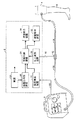
図2は、好ましい実施例の主要なコンポーネントの相互接続を示す好ましい実施例の単純化された概略図である。
【0025】
電源24は3ボルトのリチウム-イオン・バッテリである。図2において、電源24の正端子はVbattとして示され、負端子は接地されて示されている。電源24は、以下に記載するように電圧検出装置22及び低電圧検出装置26によって用いられる、Vrefとして示された1.5ボルトの基準電圧を発生する電圧調整装置34に接続されている。
【0026】
論理回路を記述するときの一般的な方法であるように、用語「ハイ」及び「ロー」は、図2に示す回路図の以下の説明において信号の状態を記述するために用いられる。信号が「ハイ」と記載されているとき、その電圧は電源24によって生じた電圧のレベルに近い。信号が「ロー」と記載されているとき、その電圧はゼロに近い。
【0027】
圧力変換装置20の常閉電気接点対は、スイッチの記号として図2に示されている。一方のスイッチ接点は接地され、他方のスイッチ接点は、Vbattと直列に高インピーダンス・プルアップ抵抗器36に接続されていると共にANDゲート38の1つの入力に接続されている。圧力変換装置20によって感知された圧力が所定の圧力より小であるとき、圧力変換装置20のスイッチ接点は閉位置にあり、ANDゲート38の入力での信号レベルはローである。圧力変換装置24によって感知された圧力が所定の圧力より大であるとき、圧力変換装置20のスイッチ接点は開位置にあり、ANDゲート38の入力での信号レベルはハイである。
【0028】
電圧検出装置22は、アナログ比較器40と、分圧回路網として構成された高インピーダンス抵抗器42及び44とを含む。止血機器8内の被監視コンポーネントからの電圧信号は、Vtournとして図2に示されている。電気ケーブル18によって伝導されたVtournは、抵抗器42及び44によって形成された分圧回路網に伝えられる。アナログ比較器40は、抵抗器42と抵抗器44との接続点で分圧されたVtourn信号のレベルと基準電圧Vrefのレベルとを比較する。Vtournからの分圧信号のレベルがVrefのレベルより小であるとき、アナログ比較器40の出力での信号レベルはローであるように、アナログ比較器40は構成されている。Vtournからの分圧信号のレベルがVrefのレベルより大であるとき、アナログ比較器40の出力での信号レベルはハイである。Vtournからの分圧信号のレベルがVrefのレベルに近いとき、アナログ比較器40はその出力信号の変動を防止するためにヒステリシスを有する。
【0029】
低電圧監視装置26は、アナログ比較器46と、分圧回路網として構成された高インピーダンス抵抗器48及び50とを含む。Vbattは、抵抗器48及び50によって形成された分圧回路網に接続されている。アナログ比較器46は、抵抗器48と抵抗器50との接続点で分圧されたVbatt信号のレベルと基準電圧Vrefのレベルとを比較する。Vbattからの分圧信号のレベルがVrefのレベルより小であるときアナログ比較器46の出力での信号レベルはローであるように、アナログ比較器46は構成されている。Vbattからの分圧信号のレベルがVrefのレベルより大であるときアナログ比較器46の出力での信号レベルはハイである。Vbattからの分圧信号のレベルがVrefのレベルに近いとき、アナログ比較器46はその出力信号の変動を防止するためにヒステリシスを有する。
【0030】
警報制御装置28は、低電圧CMOS論理ゲート、ANDゲート38、ORゲート52及びNOTゲート54及び56を介して与えられる。図2に示すように、警報制御装置28を含む論理ゲートは、警報制御装置28の出力が、次の(a)又は(b)のいずれかのとき、ハイレベルである警報信号であるように構成されている。すなわち、(a)…電圧検出装置22からの信号がローレベルで、圧力変換装置20に接続されたプルアップ抵抗器36からの信号がハイレベルであるとき、又は(b)…低電圧検出装置26からの信号がローレベルであるときのいずれかである。
【0031】
図2に示すように、警報制御装置28の出力は、正端トリガー単安定マルチバイブレータ58のクロック入力と、負端トリガー単安定マルチバイブレータ60のクロック入力と、聴覚教示装置32とに伝送される。正端トリガー単安定マルチバイブレータ58は視覚教示装置30のセット入力端子に接続された出力端子を有し、負端トリガー単安定マルチバイブレータ60は視覚教示装置30のリセット入力端子に接続された出力端子を有する。この構成において、警報信号がロー(警報状況が現れていない。)からハイ(警報状況が現れている。)に変化したとき、正端トリガー単安定マルチバイブレータ58は、視覚教示装置30のセット入力端子にパルスを適用し、視覚教示装置30の表示装置を非活動状態から、警報状況が現れていることを操作者に示す活動状態へ変化させる。警報信号がハイからローに変化したとき、負端トリガー単安定マルチバイブレータ60は、視覚教示装置30のリセット入力端子にパルスを適用し、視覚教示装置30の表示装置を活動状態から非活動状態へ変化させる。視覚教示装置30のセット及びリセットの入力端子に適用された電流及び電圧が視覚教示装置8の状態を変化するのに十分であるように、正端トリガー単安定マルチバイブレータ58及び負端トリガー単安定マルチバイブレータ60によって生じたパルスの幅および振幅は構成されている。図2に示すように、警報制御装置28からの警報信号出力は、また、聴覚教示装置32と、警報信号がハイであるとき聴覚警報を発生する圧電パルス音発生装置とに送られる。
【0032】
危険監視装置2を種々の様式の従来の止血装置に組み入れることが可能であることは、当業者にとって明らかである。たとえば、望むならば、危険監視装置2の変換装置20は、止血機器8が危険監視装置2を経て止血帯カフ4に接続されるように、前記の好ましい実施例において示したT字の継手のアダプタを用いることなく機器8とカフ4との間の気送管と一線に直接的に接続することができる。
【0033】
望むならば、危険監視装置2は、従来の止血機器に物理的に組み入れることができ、同じ物理的ハウジングっであるが独立の回路、電源及び警報装置を有する物理的ハウジングを共有する。危険監視装置は、さらに、共通のバッテリ又は同じ共通の聴視覚警報装置又は総体的な設計を単純化しかつ全費用を減少すべく他のコンポーネントを共有することによって、特定の様式の従来の止血機器に完全に組み入れることができる。たとえば、従来装置のマッキーン‘099は、止血帯カフで感知された実圧力と止血機器を介して選択された基準圧力レベルとの間の相違がカフ超過圧力限界を超えたとき、カフ超過圧力警報を発生する。そのような従来の止血帯において、聴覚及び視覚の警報教示装置は危険監視装置2の適用において用いられる。また、マッキーン‘099は、2つの空気口を有する止血帯カフを用いている。総体的な単純さ及び全費用の減少のために、危険監視装置2は、カフ圧を決定すべくカフと空気的に通じているこれらの2つの口の1つを用いることができる。
【0034】
ある従来の止血機器は、典型的には瞬時接触膜スイッチ又は低電流瞬時押しボタンスイッチとして与えられるソフト電源スイッチを有する。そのようなソフト電源スイッチは、止血機器の作動コンポーネントへの電力供給を直接的には制御しないが、止血機器の作動に必要な電力の供給を直接的に制御する他の電気的コンポーネントを制御するために作動する。本発明に係る危険監視装置は、そのような止血機器に適合されかつ組み入れられ、カフが加圧されたときに電力を遮断しようとする操作者によってソフト電源スイッチが作動されたとき、止血機器の作動に必要な電力が中断されることを防止することができる。たとえば、ジマー・ペイシャント・ケア・ディビジョン(Zimmer Patient Care Division)社(オハイオ州ドーバー(Dover))製の型番A.T.S.2000及びA.T.S.750の各従来の止血機器は、操作者がソフト電源スイッチを作動させることによって電力供給の中断を開始させた後のみにおいて、機器の作動に必要な電力の供給の中断を生じさせるソフト電源スイッチを含み、A.T.S.2000の場合において、少なくとも2秒の連続した時間、ソフト電源スイッチを作動させ続ける。カフでの加圧ガスの出現が、操作者によるスイッチの作動と同時に適合及び組み入れられた危険監視装置によって検出されたとき、ソフト電源スイッチを作動させる操作者による電力中断の開始は、止血機器の作動に必要な電力の中断を発生しないように、本発明に係る危険監視装置は、前記の従来の止血機器に適合かつ組み入れることができる。
【0035】
危険監視装置2が2つのカフと該両カフを制御する1つの止血機器とを同時に監視するように適合されることは当業者にとって明らかであり、また、危険監視装置2がデュアルポートのカフと該カフに接続された止血機器とを監視するように適合されることは当業者にとって明らかである。さらに、LED、LCD及びオーディオスピーカが、止血機器及びその付近の機器を操作する人が知覚できる視覚及び聴覚の警報装置の他の様式を与えるために用いられうることは、当業者にとって明らかである。
【図面の簡単な説明】
【図1】 外科的適用における好ましい実施例のブロック図。
【図2】 好ましい実施例の回路図。
【符号の説明】
2 危険監視装置
4 止血帯カフ
6 肢
8 止血機器
10、14、16 気送管
12 空気連結器
18 電気ケーブル
20 圧力変換装置
22 電圧検出装置
24 電源
26 低電圧検出装置
28 警報制御装置
30 視覚教示装置
32 聴覚教示装置[0001]
BACKGROUND OF THE INVENTION
The present invention relates generally to an apparatus and method for monitoring a surgical hemostasis device to detect danger. The present invention is particularly, but not limited to, the air cuff of an electrically operated surgical hemostasis device is pressurized when the power required to operate one or more components of the surgical hemostasis device is not supplied to the component. The present invention relates to a danger monitoring device having means for detecting whether or not the cuff is pressed when an operator tries to prevent the supply of electric power necessary for the operation of the device.
[0002]
[Prior art]
In general, the surgical procedure is facilitated by stopping the flow of arterial blood to the limb for a time sufficient to perform the surgical procedure, thereby allowing the surgical procedure to be performed in dry and bloodless surgical areas. In order to do this, a surgical hemostasis device is used.
[0003]
According to the presentation of published medical literature, the use of surgical hemostasis inevitably causes some damage to nerves, muscles and soft tissues of the limbs below the cuff and distal to the cuff. To minimize the nature and extent of such damage, tourniquet operators seek to minimize the degree of cuff pressure to establish and maintain a bloodless surgical area distal to the cuff. Try. Also, in order to minimize the damage associated with the tourniquet, the tourniquet operator attempts to minimize the pressurization time of the tourniquet cuff. Because the medical literature has shown that the likelihood and severity of tourniquet-related damage may appear in a patient's limb increases as the time spent wearing the tourniquet increases, Unnecessarily long pressurization is dangerous.
[0004]
Prior art surgical hemostasis devices generally include an air cuff for surrounding the patient's limb at a location near the surgical location, a pressurized gas source and equipment air-connected to the cuff, and a cuff at a regulated pressure. And a gas supply source for supplying gas.
[0005]
In some prior art hemostatic devices, the source of pressurized gas is a tank or hospital gas supply, and in other prior art devices an electric air pump is incorporated into the instrument. Surgical hemostasis devices known in the prior art incorporate a plurality of electrically actuated components including an electronic pressure transducer, a microprocessing device, a display and an audiovisual alarm. Although surgical hemostasis devices that do not have electro-actuated components are still used slightly, most currently used surgical hemostasis devices are electrically powered in whole or in part .
[0006]
Electromedics, a product of Electromedics Inc., located in Englewood, Colorado, is one type of hemostatic device that is partially powered by electricity known in the prior art. There is a TCPM Tourniquet Cuff Pressure Monitor. The device includes an electrically activated display component that displays the cuff pressure set by the operator, an electrically activated elapsed time clock that allows the operator to monitor the cuff inflation time, Includes a non-electric air switch component that allows the cuff to expand and contract and a non-electric pressure regulator that supplies gas to the cuff at a pressure close to a set pressure. The device power switch controls the power supply from the battery in the device to the electrical component when the operator turns on the device power switch. This device from Electromedics does not incorporate an electric pump, but instead requires the use of either a gas tank or a hospital central gas supply as a source of pressurized gas.
[0007]
Prior art Electromedix instruments allow the operator to first cuff the cuff using a non-electric air switch component when the pressurized tourniquet cuff is no longer needed near the end of the surgical procedure. It is designed so that it can be deflated and then the power switch can be used to stop supplying power to the electrical components. However, when the operator accidentally interrupts power supply at some stage during the surgical procedure and does not depressurize the cuff using another air switch, the cuff is powered by the electrical pressure indicator. While not being displayed on the screen, it remains pressurized at a pressure close to that adjusted by the non-electric pressure regulator. When an untrained or unfamiliar operator mistakenly determines that the cuff is deflated because the pressure indicator is blank, this results in an extended period of time until the cuff is pressurized. Errors pose a significant risk for the patient. The likelihood and severity of tourniquet-related damage in the patient's limb has been demonstrated to increase as the time spent wearing the tourniquet increases, so it is unnecessarily prolonged. Cuff pressurization is dangerous.
[0008]
A fully electrically operated hemostatic device known in the prior art is disclosed by McEwen, described in US Pat. No. B1-4,469,099, which is incorporated herein by reference. This is a hemostatic device. The hemostatic device (hereinafter referred to as “McKine '099”) manufactured by McKin described in the above-mentioned US Patent Publication includes an electrically operated device, and an electric air pump incorporated in the device as a source of pressurized gas. A surgical hemostasis device comprising: McKin '099 is operable with power supplied by an external AC power source supplemented by an internal battery and includes the following electrically operated components: That is, McKin '099 has an operation interface that allows the operator to set the tourniquet cuff pressure and the expected cuff pressurization time, a switch that allows the operator to start cuff pressurization and decompression, and the operator A cuff pressure display that can set the cuff pressure and monitor the actual cuff pressure, a micro-processor control pressure regulator that adjusts the cuff pressure close to the set pressure, and a surgeon where the operator is pressurizing the cuff And a time display device capable of specifying a target time and monitoring an elapsed time during which the cuff is pressurized.
[0009]
McKin '099 also has various electronic activations for operation warnings of certain hazardous situations that appear during operation, including warnings of over-cuff pressure, under-cuff pressure, or over-cuff press time. Audio-visual alarm device. When the supply of external AC power to McKin '099 is unexpectedly interrupted while the cuff is pressurized, the internal battery will continue to supply power to the display and alarm device, but the pressure regulator will not operate. Once complete, the instrument's barometric valve seals the pressurized cuff to hold the cuff at a predetermined pressure as much as possible or until external AC power is restored and normal operation resumes. Thus, when an interruption of external AC power occurs during a surgical procedure, McKin '099 retains in the limb distal to the unexpected flow of arterial blood to the surgical area, massive loss of blood and cuff during the procedure Prevent dangerous things for the patient, such as loss of intravenous anesthetics. However, the operator accidentally turned off the device's power switch without first retracting the tourniquet cuff, did not release the cuff from the air connection with the device, and did not remove the cuff from the patient's limb for an extended period of time Sometimes an unusual style risk arises. Turning off the McKean '099 power switch interrupts the supply of power from both the external AC power source and the internal battery. Therefore, when such an operator error occurs and no power is supplied, the McKin '099 cuff pressure display device and time display device are not displayed, and the audiovisual alarm device does not function and is not trained. Alternatively, an unfamiliar operator may erroneously determine that the cuff is contracted because the display device is not displayed. In McKean '099, the operator should pay attention to the danger that the tourniquet cuff will remain pressurized and pressure will be applied to the patient's limb for an extended period of time after interruption of power supply to the hemostatic device No audiovisual alarm device is provided.
[0010]
Other surgical hemostasis devices known in the prior art are powered entirely from an external AC power source and do not have an internal supplemental battery like McKean '099. Indication of any pressure and time contained in such equipment when there is an interruption in power supply to this other conventional device, such as resulting from AC power loss or operator error during a surgical procedure The device is blanked, no audiovisual warning device is functioning, and the pressurized cuff prevents the above-mentioned mode of danger that would otherwise occur to the patient when the cuff tries to immediately depressurize due to interruption of power supply Therefore, it is sealed with air. However, this conventional device does not provide an audiovisual warning device so that the operator can pay attention to the danger that the tourniquet cuff remains pressurized for an extended time after the interruption of power supply.
[0011]
Some conventional hemostatic devices typically have a “soft” power switch (hereinafter referred to as a “soft power switch”) such as a momentary contact membrane switch or a low current momentary pushbutton switch. Such a soft power switch does not directly control the power supply to the operating components of the hemostatic device, but operates to directly control the supply of power necessary to operate the hemostatic device. For example, a conventional hemostatic device, product model A.Z. manufactured by Zimmer Patient Care Division, Dover, Ohio, USA. T.A. S. 2000 and A.I. T.A. S. Each hemostatic device 750 includes a soft power switch that causes an interruption in the supply of power necessary for the operation of the device only after the operator has initiated an interruption in power supply by operating the soft power switch.
[0012]
A surgical hemostasis device or monitoring device capable of detecting the presence of a pressurized air cuff of a surgical hemostasis device when the power necessary for correct operation of the surgical hemostasis device is not supplied to the device is known in the prior art. unknown. Furthermore, it prevents the operator from interrupting the supply of power necessary for the operation of the hemostatic device when the operator starts interrupting the supply of power while the air cuff connected to the hemostatic device is pressurized. No electrically actuated hemostatic device is known in the prior art.
[0013]
DETAILED DESCRIPTION OF THE INVENTION
The preferred embodiments shown in the figures are not intended to be exhaustive and are not strictly limited to the forms disclosed. The embodiments shown in the figures have been chosen and described to illustrate the principles of the invention, its application and practical use, so that those skilled in the art can use the invention.
[0014]
FIG. 1 shows a
[0015]
As shown in FIG. 1, the
[0016]
As shown in FIG. 1, the tourniquet cuff 4 is in air communication with the
[0017]
In the preferred embodiment, the power supply to components of the hemostatic device 8 that require power for operation is monitored by monitoring the voltage level at the component. In the preferred embodiment, when the voltage level monitored at the component is below a predetermined voltage level, it is determined that no power is being supplied to the component. The power supply to the component can be selectively monitored by monitoring the level of current flowing through the component. In the preferred embodiment, as shown in FIG. 1, the
[0018]
As can be seen from FIG. 1, the
[0019]
The low
[0020]
The
[0021]
When an alarm signal is generated by the
[0022]
When the tourniquet cuff 4 is applied to the patient's limb, the hemostatic device 8 supplies pressurized gas to the cuff 4 during the surgical procedure, and the
[0023]
When the cuff 4 is not pressurized above a predetermined pressure level, the switch contact of the
[0024]
FIG. 2 is a simplified schematic diagram of the preferred embodiment showing the interconnection of the main components of the preferred embodiment.
[0025]
The
[0026]
As is common practice when describing logic circuits, the terms “high” and “low” are used to describe signal states in the following description of the circuit diagram shown in FIG. When the signal is listed as “high”, the voltage is close to the level of the voltage generated by the
[0027]
The normally closed electrical contact pair of the
[0028]
The
[0029]
The low
[0030]
The
[0031]
As shown in FIG. 2, the output of the
[0032]
It will be apparent to those skilled in the art that the
[0033]
If desired, the
[0034]
One conventional hemostatic device has a soft power switch, typically provided as a momentary contact membrane switch or a low current momentary pushbutton switch. Such a soft power switch does not directly control the power supply to the operating components of the hemostatic device, but controls other electrical components that directly control the supply of power necessary to operate the hemostatic device. Operates for. The danger monitoring device according to the present invention is adapted and incorporated into such a hemostatic device, and when the soft power switch is activated by an operator who wants to cut off power when the cuff is pressurized, It is possible to prevent the power necessary for the operation from being interrupted. For example, model number A.M. manufactured by Zimmer Patient Care Division (Dover, Ohio). T.A. S. 2000 and A.I. T.A. S. Each of the 750 conventional hemostatic devices has a soft power switch that causes an interruption in the supply of power necessary for the operation of the device only after the operator has initiated a power supply interruption by activating the soft power switch. Including A. T.A. S. In the case of 2000, continue to operate the soft power switch for at least 2 seconds of continuous time. When the appearance of pressurized gas in the cuff is detected by a hazard monitoring device that is adapted and incorporated at the same time that the operator activates the switch, the start of the power interruption by the operator operating the soft power switch is The danger monitoring device according to the present invention can be adapted and incorporated into the above conventional hemostatic device so as not to interrupt the power necessary for operation.
[0035]
It will be apparent to those skilled in the art that the
[Brief description of the drawings]
FIG. 1 is a block diagram of a preferred embodiment in a surgical application.
FIG. 2 is a circuit diagram of a preferred embodiment.
[Explanation of symbols]
2 Danger monitoring device
4 tourniquet cuff
6 limbs
8 hemostatic equipment
10, 14, 16 Air pipe
12 Air coupler
18 Electric cable
20 Pressure transducer
22 Voltage detector
24 power supply
26 Low voltage detector
28 Alarm control device
30 Visual teaching device
32 Auditory teaching device
Claims (10)
止血機器の電動作動のコンポーネントへの電力の供給を監視する電力監視手段と、
前記止血帯カフ内に圧力が検出された場合であってかつ前記止血機器の前記コンポーネントに電力が供給されていないときに警報信号を発するよう前記圧力変換手段と前記電力監視手段との両者に応答する危険検出手段とを含み、
前記止血機器は、前記止血帯カフへ加圧ガスを供給して該止血帯カフに圧力を発生するように、前記止血帯カフに空気接続可能である、外科的止血システム用危険監視装置。Pressure converting means for detecting the pressure in the air tourniquet cuff;
Power monitoring means for monitoring the supply of power to electrically operated components of the hemostatic device;
Responding to both the pressure converting means and the power monitoring means to issue an alarm signal when pressure is detected in the tourniquet cuff and no power is supplied to the component of the hemostatic device And a danger detection means for
The surgical hemostasis system risk monitoring apparatus, wherein the hemostasis device is air connectable to the tourniquet cuff so as to supply pressurized gas to the tourniquet cuff and generate pressure on the tourniquet cuff.
前記コンポーネントは、電力が供給されているとき、前記圧力調整手段によって供給されるガス圧を示す表示を生じさせるよう作動する、請求項1に記載の装置。Pressure regulating means operable to supply a pressurized gas close to the regulated pressure over a suitable length of time for performing a surgical procedure;
The apparatus of claim 1, wherein the component is operative to produce an indication indicating a gas pressure supplied by the pressure regulating means when power is supplied.
前記空気圧式止血帯カフ内のガスの圧力が所定の圧力レベルより大きくなったときを検知するステップと、
前記外科的止血機器の電動コンポーネントへの電力の供給を監視するステップと、
所定の圧力レベルより大きい圧力のガスが前記空気圧式止血帯カフ内で検出されており、かつ電力が前記外科的止血機器の前記電気コンポーネントへ供給されていない場合を決定するステップと、
所定の圧力レベルより大きい圧力のガスが前記空気圧式止血帯カフ内で検出されており、かつ電力が前記外科的止血機器の前記電気コンポーヘントへ供給されていない場合に、人が知覚できる警報を発生するステップとを含み、
前記外科的止血機器は、電力が前記コンポーネントに供給されているときに前記止血帯カフへ加圧ガスを供給するよう作動する、警報を発する方法。A method for issuing a warning indicating a danger associated with a powered surgical tourniquet device connected to a pneumatic tourniquet cuff, comprising:
Detecting when the pressure of the gas in the pneumatic tourniquet cuff is greater than a predetermined pressure level;
Monitoring the supply of power to the electrical components of the surgical hemostasis device;
Determining when a gas at a pressure greater than a predetermined pressure level has been detected in the pneumatic tourniquet cuff and power is not being supplied to the electrical component of the surgical tourniquet instrument;
Generates an alarm that can be perceived by a person when a gas with a pressure greater than a predetermined pressure level is detected in the pneumatic tourniquet cuff and power is not supplied to the electrical component of the surgical hemostasis device Including the steps of:
An alarming method wherein the surgical hemostasis device is operative to supply pressurized gas to the tourniquet cuff when power is applied to the component.
前記操作者による前記スイッチの作動状況を監視するステップと、
前記操作者がスイッチを作動させたときに前記外科的止血機器に接続された空気圧式止血帯カフ内のガスが所定の圧力レベルよりも大きいか否かを検知するステップと、
前記スイッチの作動中に前記所定の圧力レベルより大きい圧力のガスが前記空気圧式止血帯カフ内で検出された場合、前記スイッチ信号が前記電源の供給を中断しないようにするステップとを含む、操作者によって電力供給の中断がなされることを防ぐ方法。Interruption of power supply by an operator when it is dangerous to interrupt the supply of power required to operate the surgical hemostasis device, including a switch that generates a switch signal that controls the power supply to the surgical hemostasis device Is a way to prevent
Monitoring the operating status of the switch by the operator;
Detecting whether gas in a pneumatic tourniquet cuff connected to the surgical hemostasis device is greater than a predetermined pressure level when the operator activates a switch;
Ensuring that the switch signal does not interrupt the supply of power if gas at a pressure greater than the predetermined pressure level is detected in the pneumatic tourniquet cuff during operation of the switch. To prevent interruption of power supply by a person.
前記圧力調整手段が必要とする電力の供給の中断を操作者が開始できるようにする電源スイッチ手段と、
前記操作者が膨張可能なカフと前記圧力調整手段とを気密に接続して、前記圧力調整手段が発生した前記加圧ガスの、前記膨張可能なカフへの通路を確立させることを可能にする空気接続手段と、
前記電力の供給の中断が前記操作者によって開始されたときに、所定の圧力レベルより大きい圧力を有する加圧ガスを検出し、前記電力の供給の中断が前記操作者によって開始されたときに前記所定の圧力レベルより大きい圧力を有するガスが検出された場合に電源の供給を中断させないようにする、前記空気接続手段と気密に連通している危険監視手段とを含む、危険監視装置を有する外科的止血機器。Pressure adjusting means for generating a pressurized gas over a sufficient length of time to perform a surgical procedure, wherein the pressure adjusting means requires a supply of power to generate the pressurized gas;
A power switch means for allowing an operator to start interrupting the supply of power required by the pressure adjusting means;
Allowing the operator to hermetically connect the inflatable cuff and the pressure adjusting means to establish a passage of the pressurized gas generated by the pressure adjusting means to the inflatable cuff; Air connection means;
When an interruption of the supply of power is initiated by the operator, a pressurized gas having a pressure greater than a predetermined pressure level is detected, and when the interruption of the supply of power is initiated by the operator Surgical device having a risk monitoring device including the air connection means and a risk monitoring means in airtight communication so as not to interrupt the supply of power when a gas having a pressure greater than a predetermined pressure level is detected. Hemostatic device.
該カフは、患者の肢に巻き付けられ、前記空気接続手段に接続され、加圧ガスによって膨張すると、巻き付けられた前記肢に圧力を作用させる、請求項9に記載の外科的止血機器。An inflatable cuff that is hermetically connectable with the air connection means;
The surgical hemostasis device of claim 9 , wherein the cuff is wrapped around a patient's limb, connected to the air connection means, and exerts pressure on the wrapped limb when inflated by pressurized gas.
Applications Claiming Priority (3)
| Application Number | Priority Date | Filing Date | Title |
|---|---|---|---|
| US09/210,221 US6213939B1 (en) | 1998-12-10 | 1998-12-10 | Hazard monitor for surgical tourniquet systems |
| US09/210,221 | 1998-12-10 | ||
| PCT/CA1999/000184 WO2000033748A1 (en) | 1998-12-10 | 1999-03-02 | Hazard monitor for surgical tourniquet systems |
Publications (3)
| Publication Number | Publication Date |
|---|---|
| JP2002531212A JP2002531212A (en) | 2002-09-24 |
| JP2002531212A5 JP2002531212A5 (en) | 2006-04-20 |
| JP4091259B2 true JP4091259B2 (en) | 2008-05-28 |
Family
ID=22782049
Family Applications (1)
| Application Number | Title | Priority Date | Filing Date |
|---|---|---|---|
| JP2000586245A Expired - Lifetime JP4091259B2 (en) | 1998-12-10 | 1999-03-02 | Hazard monitoring device for surgical hemostasis device |
Country Status (9)
| Country | Link |
|---|---|
| US (1) | US6213939B1 (en) |
| EP (1) | EP1137368B1 (en) |
| JP (1) | JP4091259B2 (en) |
| CN (1) | CN100518670C (en) |
| AU (1) | AU762365B2 (en) |
| CA (1) | CA2353977C (en) |
| DE (1) | DE69927049T2 (en) |
| IL (2) | IL143583A0 (en) |
| WO (1) | WO2000033748A1 (en) |
Families Citing this family (43)
| Publication number | Priority date | Publication date | Assignee | Title |
|---|---|---|---|---|
| US6589268B1 (en) * | 1998-12-10 | 2003-07-08 | Mcewen James A. | Hazard monitor for surgical tourniquet systems |
| EP1229839A4 (en) * | 1999-10-25 | 2005-12-07 | Therus Corp | Use of focused ultrasound for vascular sealing |
| US6626855B1 (en) * | 1999-11-26 | 2003-09-30 | Therus Corpoation | Controlled high efficiency lesion formation using high intensity ultrasound |
| US6946988B2 (en) * | 2000-11-10 | 2005-09-20 | Simple Devices | Detachable remote controller for an electronic entertainment device and a method for using the same |
| US6682547B2 (en) | 2001-08-14 | 2004-01-27 | Mcewen James Allen | Tourniquet cuff with identification apparatus |
| US7331977B2 (en) * | 2001-08-14 | 2008-02-19 | Mcewen James A | Adaptive tourniquet cuff system |
| US6746470B2 (en) | 2002-01-18 | 2004-06-08 | Mcewen James Allen | Emergency and military tourniquet for pre-hospital use |
| WO2006071251A2 (en) * | 2004-04-07 | 2006-07-06 | Tiax Llc | Tourniquet and method of using same |
| US8961461B2 (en) * | 2004-05-27 | 2015-02-24 | Baxter International Inc. | Multi-state alarm system for a medical pump |
| US20070194658A1 (en) * | 2005-07-13 | 2007-08-23 | Jimin Zhang | Systems and methods for performing acoustic hemostasis of deep bleeding trauma in limbs |
| US7955352B2 (en) * | 2005-08-05 | 2011-06-07 | Western Clinical Engineering, Ltd | Surgical tourniquet cuff for limiting usage to improve safety |
| US8167805B2 (en) * | 2005-10-20 | 2012-05-01 | Kona Medical, Inc. | Systems and methods for ultrasound applicator station keeping |
| US7802333B2 (en) * | 2007-02-12 | 2010-09-28 | O.R. Comfort, Llc | Inflatable surgical positioning aid |
| US7938846B2 (en) * | 2007-06-22 | 2011-05-10 | Radi Medical Systems Ab | Femoral compression device |
| US8425426B2 (en) | 2007-11-09 | 2013-04-23 | Western Clinical Engineering, Ltd | Tourniquet apparatus for measuring limb occlusion pressure |
| US8083763B2 (en) * | 2009-02-10 | 2011-12-27 | Western Clinical Engineering Ltd. | Apparatus and method for estimating leakage in a surgical tourniquet system |
| US9113895B2 (en) * | 2009-02-19 | 2015-08-25 | Western Clinical Engineering Ltd. | Integrated tourniquet system |
| US8469904B2 (en) | 2009-10-12 | 2013-06-25 | Kona Medical, Inc. | Energetic modulation of nerves |
| US8517962B2 (en) | 2009-10-12 | 2013-08-27 | Kona Medical, Inc. | Energetic modulation of nerves |
| US20110092880A1 (en) | 2009-10-12 | 2011-04-21 | Michael Gertner | Energetic modulation of nerves |
| US8986231B2 (en) | 2009-10-12 | 2015-03-24 | Kona Medical, Inc. | Energetic modulation of nerves |
| US20110118600A1 (en) | 2009-11-16 | 2011-05-19 | Michael Gertner | External Autonomic Modulation |
| US8295912B2 (en) | 2009-10-12 | 2012-10-23 | Kona Medical, Inc. | Method and system to inhibit a function of a nerve traveling with an artery |
| US9174065B2 (en) | 2009-10-12 | 2015-11-03 | Kona Medical, Inc. | Energetic modulation of nerves |
| US9119951B2 (en) | 2009-10-12 | 2015-09-01 | Kona Medical, Inc. | Energetic modulation of nerves |
| US8986211B2 (en) | 2009-10-12 | 2015-03-24 | Kona Medical, Inc. | Energetic modulation of nerves |
| US20160059044A1 (en) | 2009-10-12 | 2016-03-03 | Kona Medical, Inc. | Energy delivery to intraparenchymal regions of the kidney to treat hypertension |
| AU2011282420B2 (en) * | 2010-07-23 | 2014-11-06 | Western Clinical Engineering Ltd. | Tourniquet hazard suppressor |
| CN102240219A (en) * | 2011-07-19 | 2011-11-16 | 李悦 | Hand pressure quantitative regulation hemostasis device |
| SG11201500759PA (en) * | 2012-07-30 | 2015-03-30 | Univ Kochi Nat Univ Corp | In vivo acetylcholine production-promoting device |
| US9393027B1 (en) | 2012-08-02 | 2016-07-19 | Frank Gleason I.P., Llc | Intravenous assist device |
| DE102012110827A1 (en) * | 2012-11-12 | 2014-05-15 | Ulrich Gmbh & Co. Kg | Control device and control system for a tourniquet device |
| CN103462670A (en) * | 2013-10-09 | 2013-12-25 | 初君 | Hemostatic device and hand-operated tourniquet electronic display thereof |
| US20140253328A1 (en) * | 2014-05-23 | 2014-09-11 | Jessel Craig | Hazard warning apparatus and system and method for use thereof |
| US9877733B1 (en) * | 2014-09-12 | 2018-01-30 | Mohammad R. Jafary | Anti-necrosis tourniquet device |
| US10925579B2 (en) | 2014-11-05 | 2021-02-23 | Otsuka Medical Devices Co., Ltd. | Systems and methods for real-time tracking of a target tissue using imaging before and during therapy delivery |
| CN106974690A (en) * | 2016-01-19 | 2017-07-25 | 李秀玲 | A kind of surgical nursing hemostasis device |
| US10136903B2 (en) | 2016-03-28 | 2018-11-27 | Patrick James LYNCH | Tourniquet and method thereof having compliance logging and alert features, and a system thereof |
| CN105726083A (en) * | 2016-04-22 | 2016-07-06 | 深圳市前海康启源科技有限公司 | Pneumatic automatic hemostasis equipment and pneumatic automatic hemostasis method |
| GB2564111B (en) * | 2017-07-03 | 2022-03-02 | Jessup Mark | Tourniquet Apparatus |
| CN109998620A (en) * | 2019-03-01 | 2019-07-12 | 齐鲁工业大学 | A kind of automatic air pressure haemostat measurement and control system based on self adaptive control |
| US11723670B2 (en) * | 2021-03-16 | 2023-08-15 | Western Clinical Engineering Ltd. | Automatic tourniquet apparatus having patient hazard shield |
| US20230240689A1 (en) * | 2022-01-28 | 2023-08-03 | Ingenio Technology Co., Limited | Automatic unlock device for tourniquet |
Family Cites Families (13)
| Publication number | Priority date | Publication date | Assignee | Title |
|---|---|---|---|---|
| US4106002A (en) | 1976-12-06 | 1978-08-08 | Hogue Jr Robert J | Tourniquet pressure monitor |
| US4321929A (en) | 1979-10-12 | 1982-03-30 | Lemelson Jerome H | Tourniquet |
| US4469099A (en) | 1980-10-02 | 1984-09-04 | Western Clinical Engineering Ltd. | Pneumatic torniquet |
| US4479494A (en) | 1982-01-05 | 1984-10-30 | Western Clinical Engineering Ltd. | Adaptive pneumatic tourniquet |
| US4520820A (en) | 1983-04-15 | 1985-06-04 | Aspen Laboratories, Inc. | Automatic tourniquet with improved pressure resolution |
| US4671290A (en) | 1985-01-15 | 1987-06-09 | Richards Medical Company | Automatic tourniquet |
| US5181522A (en) | 1987-04-03 | 1993-01-26 | Abatis Medical Technologies Limited | Tourniquet for sensing and regulation of applied pressure |
| US5607447A (en) | 1993-09-28 | 1997-03-04 | Mcewen; James A. | Physiologic tourniquet |
| US5254087A (en) | 1990-01-29 | 1993-10-19 | Ivra Systems, Inc. | Tourniquet apparatus for intravenous regional anesthesia |
| US5556415A (en) | 1990-01-29 | 1996-09-17 | Mcewen; James A. | Physiologic tourniquet for intravenous regional anesthesia |
| DE4317600C2 (en) | 1993-05-27 | 1995-07-13 | Ulrich Heinrich C | Compression apparatus for creating an artificial void on the extremities |
| US5843007A (en) | 1996-04-29 | 1998-12-01 | Mcewen; James Allen | Apparatus and method for periodically applying a pressure waveform to a limb |
| US5681339A (en) | 1996-08-12 | 1997-10-28 | Mcewen; James A. | Apparatus and method for monitoring the patency of tubing in a pneumatic medical device |
-
1998
- 1998-12-10 US US09/210,221 patent/US6213939B1/en not_active Expired - Lifetime
-
1999
- 1999-03-02 JP JP2000586245A patent/JP4091259B2/en not_active Expired - Lifetime
- 1999-03-02 WO PCT/CA1999/000184 patent/WO2000033748A1/en active IP Right Grant
- 1999-03-02 IL IL14358399A patent/IL143583A0/en active IP Right Grant
- 1999-03-02 CN CNB99814309XA patent/CN100518670C/en not_active Expired - Fee Related
- 1999-03-02 DE DE69927049T patent/DE69927049T2/en not_active Expired - Lifetime
- 1999-03-02 CA CA002353977A patent/CA2353977C/en not_active Expired - Lifetime
- 1999-03-02 EP EP99973249A patent/EP1137368B1/en not_active Expired - Lifetime
- 1999-03-02 AU AU32432/99A patent/AU762365B2/en not_active Expired
-
2001
- 2001-06-05 IL IL143583A patent/IL143583A/en not_active IP Right Cessation
Also Published As
| Publication number | Publication date |
|---|---|
| CA2353977C (en) | 2009-01-06 |
| AU762365B2 (en) | 2003-06-26 |
| CA2353977A1 (en) | 2000-06-15 |
| US6213939B1 (en) | 2001-04-10 |
| DE69927049T2 (en) | 2006-03-09 |
| JP2002531212A (en) | 2002-09-24 |
| AU3243299A (en) | 2000-06-26 |
| WO2000033748A1 (en) | 2000-06-15 |
| EP1137368A1 (en) | 2001-10-04 |
| CN1330527A (en) | 2002-01-09 |
| CN100518670C (en) | 2009-07-29 |
| EP1137368B1 (en) | 2005-08-31 |
| DE69927049D1 (en) | 2005-10-06 |
| IL143583A (en) | 2006-07-05 |
| IL143583A0 (en) | 2002-04-21 |
Similar Documents
| Publication | Publication Date | Title |
|---|---|---|
| JP4091259B2 (en) | Hazard monitoring device for surgical hemostasis device | |
| JP5011276B2 (en) | Blockage detector for dual port tourniquet system | |
| EP1909657B1 (en) | Surgical tourniquet cuff for limiting usage to improve safety | |
| CA2198498C (en) | Physiologic tourniquet | |
| EP2395928B1 (en) | Apparatus for estimating leakage in a surgical tourniquet system | |
| US6589268B1 (en) | Hazard monitor for surgical tourniquet systems | |
| US11723670B2 (en) | Automatic tourniquet apparatus having patient hazard shield | |
| JP2024518675A (en) | Automatic tourniquet device with patient danger shield - Patents.com |
Legal Events
| Date | Code | Title | Description |
|---|---|---|---|
| A521 | Request for written amendment filed |
Free format text: JAPANESE INTERMEDIATE CODE: A523 Effective date: 20060301 |
|
| A621 | Written request for application examination |
Free format text: JAPANESE INTERMEDIATE CODE: A621 Effective date: 20060301 |
|
| A977 | Report on retrieval |
Free format text: JAPANESE INTERMEDIATE CODE: A971007 Effective date: 20070912 |
|
| A131 | Notification of reasons for refusal |
Free format text: JAPANESE INTERMEDIATE CODE: A131 Effective date: 20070925 |
|
| A521 | Request for written amendment filed |
Free format text: JAPANESE INTERMEDIATE CODE: A523 Effective date: 20071221 |
|
| TRDD | Decision of grant or rejection written | ||
| A01 | Written decision to grant a patent or to grant a registration (utility model) |
Free format text: JAPANESE INTERMEDIATE CODE: A01 Effective date: 20080205 |
|
| A61 | First payment of annual fees (during grant procedure) |
Free format text: JAPANESE INTERMEDIATE CODE: A61 Effective date: 20080228 |
|
| R150 | Certificate of patent or registration of utility model |
Free format text: JAPANESE INTERMEDIATE CODE: R150 |
|
| FPAY | Renewal fee payment (event date is renewal date of database) |
Free format text: PAYMENT UNTIL: 20110307 Year of fee payment: 3 |
|
| FPAY | Renewal fee payment (event date is renewal date of database) |
Free format text: PAYMENT UNTIL: 20110307 Year of fee payment: 3 |
|
| FPAY | Renewal fee payment (event date is renewal date of database) |
Free format text: PAYMENT UNTIL: 20120307 Year of fee payment: 4 |
|
| FPAY | Renewal fee payment (event date is renewal date of database) |
Free format text: PAYMENT UNTIL: 20130307 Year of fee payment: 5 |
|
| FPAY | Renewal fee payment (event date is renewal date of database) |
Free format text: PAYMENT UNTIL: 20130307 Year of fee payment: 5 |
|
| FPAY | Renewal fee payment (event date is renewal date of database) |
Free format text: PAYMENT UNTIL: 20140307 Year of fee payment: 6 |
|
| R250 | Receipt of annual fees |
Free format text: JAPANESE INTERMEDIATE CODE: R250 |
|
| R250 | Receipt of annual fees |
Free format text: JAPANESE INTERMEDIATE CODE: R250 |
|
| R250 | Receipt of annual fees |
Free format text: JAPANESE INTERMEDIATE CODE: R250 |
|
| R250 | Receipt of annual fees |
Free format text: JAPANESE INTERMEDIATE CODE: R250 |
|
| R250 | Receipt of annual fees |
Free format text: JAPANESE INTERMEDIATE CODE: R250 |
|
| EXPY | Cancellation because of completion of term |