JP4091230B2 - Double thermal printer - Google Patents
Double thermal printer Download PDFInfo
- Publication number
- JP4091230B2 JP4091230B2 JP2000011602A JP2000011602A JP4091230B2 JP 4091230 B2 JP4091230 B2 JP 4091230B2 JP 2000011602 A JP2000011602 A JP 2000011602A JP 2000011602 A JP2000011602 A JP 2000011602A JP 4091230 B2 JP4091230 B2 JP 4091230B2
- Authority
- JP
- Japan
- Prior art keywords
- thermal
- paper
- thermal head
- movable frame
- head
- Prior art date
- Legal status (The legal status is an assumption and is not a legal conclusion. Google has not performed a legal analysis and makes no representation as to the accuracy of the status listed.)
- Expired - Fee Related
Links
Images


Description
【0001】
【発明の属する技術分野】
本発明は、印字装置さらには複数の用紙に印字可能な多連式印字装置に関し、例えばサーマルヘッドを備えた感熱式印字装置(いわゆるサーマルプリンタ)に利用して有効な技術に関するものである。
【0002】
【従来の技術】
情報出力装置として使用されるプリンタには、ワイヤドットプリンタのようなインパクト方式と、ノンインパクト方式とがある。さらに、ノンインパクト方式のプリンタには、レーザープリンタとサーマルプリンタとがある。このうちインパクト方式のプリンタは騒音が大きいとともに印字品質でも劣るため、近年においてはノンインパクト方式のプリンタが広く使用されるようになって来ている。また、ノンインパクト方式のプリンタのうちサーマルプリンタは小型化に適しているため、幅広い分野で利用されるようになって来ている。
【0003】
特に、POS(Point Of Sales)端末においては、顧客に渡すレシート用の出力紙と販売店の控えとして残すジャーナル用の出力紙の2つを同時に印字する必要があるため、2台のプリンタを並設したものや2つヘッドを有する2連式のプリンタが実用化されている。しかしながら、プリンタは印字ヘッドのコストがかなり高いため、各用紙に合わせてヘッドを有する多連式プリンタは、コンパクト化はある程度達成できるものの、コスト面では充分な効果が得られていなかった。
【0004】
そこで、サーマルヘッドを共通化して、この共通のサーマルヘッドに対して2つの紙送りユニットを並べて設けてやることで、小型化および経済性を向上させた2連式のサーマルプリンタに関する発明が提案されている(特許第2819595号)。
【0005】
【発明が解決しようとする課題】
しかしながら、上記先願特許発明に係るサーマルプリンタは、2枚の用紙に対して同時に印字を行なうことができる安価な装置であるという利点を有するものの、駆動ローラおよびモータが一つであり用紙送り機構のガイド部分が固定式であるため、印字される用紙の幅が固定されてしまうとともに、印字速度も2系統で同一にしなければならず、汎用性が低いという問題点があることが明らかになった。
【0006】
特に、POS端末にあっては、顧客に渡すレシート用の出力紙と販売店の控えとして残すジャーナル用の出力紙とで、出力する情報とその量を変えたい場合が多い。そのため、前述の先願特許発明に係るサーマルプリンタをPOS端末に使用する場合には、2枚の用紙のサイズ比が異なる2種類のプリンタを用意しなければならず、大幅なコストダウンは達成できない。
【0007】
しかも、前述の先願特許発明に係るサーマルプリンタは、駆動ローラおよびモータが一つであるため、2つの用紙に対する印字速度を変えることができない。そのため、出力情報量の差が大きい場合すなわち情報量が極端に異なる場合には情報量の少ない方の用紙は余白部分が多くなって無駄が生じるという課題があることが分かった。
【0008】
この発明の目的は、1つのサーマルヘッドを用いて複数の感熱用紙に印字する構成の2連式サーマルプリンタであって、各感熱用紙への印字を他の用紙への印字とは独立して行うことができる2連式のサーマルプリンタを提供することにある。
【0009】
また使用する用紙のサイズを容易に変更することができ、これによってトータルのコストを低減可能な2連式のサーマルプリンタを提供することにある。
【0010】
この発明のさらに他の目的は、2つの用紙に対する印字速度を変えることができ、これによって出力情報量に大きな差がある場合にも用紙のサイズ比をそれほど大きく変えずに対応することができる2連式のサーマルプリンタを提供することにある。
【0011】
【課題を解決するための手段】
本発明は上記のような問題点に着目してなされたもので、複数の発熱要素がライン状に配設され、複数の感熱用紙に対応した複数の部位が設定可能な1個のサーマルヘッドと、前記複数の感熱用紙を別々に移送可能な紙送り手段と、前記サーマルヘッドの全領域に対応して印字すべきデータを格納するラインメモリと、印字すべき感熱用紙に対応する前記サーマルヘッドの部位に対応したラインメモリの部位に、印字すべき感熱用紙に印字すべきデータを格納する第1のデータ格納手段と、前記ラインメモリの他の部位に、発熱要素を発熱または非発熱のいずれか一方の状態にするデータを格納する第2のデータ格納手段とを備え、2連式サーマルプリンタを構成したものである。
【0012】
この構成においてサーマルヘッドを可動にして多種の幅の感熱用紙に対応するようにするには、本体フレームと、複数の発熱要素がライン状に配設された1個のサーマルヘッドと、サーマルヘッドと並設され、前記発熱要素が配設されたライン方向に互いに並設された第1および第2のプラテンと、これらのプラテンと前記サーマルヘッドとの間にそれぞれ挿入された2枚の感熱用紙を別々に移送可能な紙送り手段と、前記サーマルヘッドを保持するとともに前記発熱要素が配設されたライン方向にスライド可能に取り付けられた可動フレームとを設け、前記サーマルヘッドに対応して印字すべきデータを格納するラインメモリと、前記2枚の感熱用紙のうち、印字すべき感熱用紙に対応する前記サーマルヘッドの部位に対応したラインメモリの部位に、印字すべき感熱用紙に印字すべきデータを格納する第1のデータ格納手段と、前記ラインメモリの他の部位に、発熱要素を発熱または非発熱のいずれか一方の状態にするデータを格納する第2のデータ格納手段とを備えて2連式サーマルプリンタを構成すればよい。
【0013】
この構成において、前記紙送り手段を、前記各感熱用紙に対応して設けられた2個の駆動モータと、該駆動モータの駆動力をそれぞれ伝達する2組の歯車減速機構とにより構成し、更に、前記印字すべき感熱用紙に対応する側の駆動モータを駆動する駆動モータ制御手段を備えることによって、各感熱用紙の送給スピードを異なるスピードに設定することができる。
【0014】
可動フレームは幅方向に動き得るが、可動フレームを前記ライン方向の任意の位置に固定するヘッド固定手段を設けてヘッドの固定を確実にするように構成してもよい。
【0015】
また、可動フレームの両端に上記感熱用紙の端部を規制する一対の規制片を設けて用紙をガイドするようにすれば、他に規制部材を設ける必要がなく構成が簡単になる。さらにまた、第1のプラテンと第2のプラテンの間には支持壁を設け、該支持壁の側面が感熱用紙の他方の端部を規制するガイド面をなすように構成してもよい。ただし、可動フレームに設けた規制部材は、プリンタの他の部位に設けてもよく、プラテン間に設けた支持壁とガイド面はなくてもよい。
【0016】
【発明の実施の形態】
以下、本発明の好適な実施例を図面に基づいて説明する。
【0017】
図1は本発明に係るサーマルプリンタの一実施例を示す斜視図、図2はそのサーマルヘッドをプラテンローラから離間した状態を示す断面側面図、図3はそのサーマルヘッドをプラテンローラに押圧した状態を示す断面側面図である。
【0018】
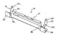
図1において、100はプリンタ、1はプリンタの本体フレーム、2a,2bはこの本体フレーム1の前端部に横架されたプラテンローラ、3はこのプラテンローラ2a,2bに対して接近離反可能に本体フレーム1に取り付けられたラインドッド型サーマルヘッド、4はこのサーマルヘッド3をプラテンローラ2に対して接近離反させる回動押圧部材である。この回動押圧部材4には上記サーマルヘッド3の背面に位置する押圧片4aとその一側に上方へ突出するように設けられた操作レバー4bとを有している。本体フレーム1はプラスチックで形成されているとともに、プラテンローラ2a,2bはその外周面が弾性材で覆われている。
【0019】
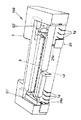
上記サーマルヘッド3は、図2に示すように、本体フレーム1の中央下部に配設されたヘッド支持軸5に嵌合された左右一対のヘッド支持片6a,6b間に固定され、ヘッド支持軸5を中心として回動可能に保持されている。そして、サーマルヘッド3は組み立て時には図2に示すようにプラテンローラ2から離反されており、上記操作レバー4bを図3の矢印Bにように前に倒すことによってプラテンローラ2a,2bに押圧されるように構成されている。
【0020】
特に限定されるものではないが、この実施例では、上記サーマルヘッド3の背面には複数枚の板バネ7が固着されており、この板バネ7の先端側は後述の可動フレーム20の後壁25に当接されている。これによって、操作レバー4bが前方へ押されたときに上記押圧片4aが回動しながら板バネ7を、図3に示すように湾曲させながら前方へ押すことによってサーマルヘッド3が板バネ7の弾性力により所定の圧力でプラテンローラ2に押圧されるように構成されている。
【0021】
また、図2に示すように、操作レバー4bの下端には押上げ片4cが設けられているとともに、上記サーマルヘッド3の一側には係合ピン3aが側方へ突出するように設けられており、上記操作レバー4bが矢印Aのように後方へ回動されると、押圧片4aが板バネ7から離れた直後に押上げ片4cが上記係合ピン3aに当接してこれを持ち上げることによりサーマルヘッド3を強制的にプラテンローラ2から離間させるように構成されている。
【0022】
この実施例においては、プラテンローラ2は、図1に示すように、本体フレーム1の側壁部1aとフレーム前端中央に立設された支持壁1cとの間に回転軸8aによって軸支された第1プラテンローラ2aと、側壁部1bと上記支持壁1cとの間に回転軸8bによって軸支された第2プラテンローラ2bの2つに分割されている。特に限定されるものではないが、この実施例では、プラテンローラ2aの方が2bよりも短く形成されている。
【0023】
2つの分割されたプラテンローラ2a,2bに応じて、本体フレーム1の両側後端部には、それぞれの駆動モータ9a,9bが取り付けられている。駆動モータ9a,9bの回転駆動力は、本体フレーム1の側壁部1a,1b内に内蔵された歯車減速機構によって上記プラテンローラ2a,2bにそれぞれ伝達されるように構成されている。
【0024】
なお、上記本体フレーム1の側壁部1aと支持壁1cとの間に上記プラテンローラ2aとほぼ並行してそのやや上方に横架されたピン10は、上記操作レバー4bの前方位置規制を行なうストッパ用のピンである。また、このピン10は、プラテンローラ2bの前方にカッターを取り付けたときにそのカッターに対して所望の角度で印字後の紙を誘導する機能も有している。プラテンローラ2aの側にのみピン10が設けられているのは、POS端末に使用された場合に、左側の用紙は販売店に記録として残しておくジャーナル用で、右側の用紙が顧客に渡されるレシート用とするため右側にのみカッターを取り付けることを想定しているからである。
【0025】
一方、サーマルヘッド3は、図1に示すように、上記プラテンローラ2a,2bにまたがって対向するように一体物として形成されているものの、その長さはプラテンローラ2aの幅と2bの幅およびプラテンローラ2a,2bの間隔を加算した全長よりは少し短く設計されている。なお、サーマルヘッド3の長さと上記プラテンローラ全長との差は、後述のサーマルヘッドスライド量に応じて決定される。云いかえると、サーマルヘッド3の長さは、プラテンローラ全長からサーマルヘッドのスライド量を引いた長さとすれば良い。
【0026】
次に、サーマルヘッド3のスライド機構について説明する。
【0027】
この実施例では、本体フレーム1の前端下面に、導電材からなる可動フレーム20が取り付けられており、この可動フレーム20はその両端に図4に示すように上方へ折曲された一対の保持片21a,21bが形成されており、この保持片21a,21bの下部に形成された貫通穴22a,22bが上記ヘッド支持軸5に嵌合されることにより、本体フレーム1の左右方向にスライド可能に構成されている。また、上記保持片21a,21bの先端部に形成された係合穴23a,23b間に上記回動押圧部材4を回動可能に支持する支持ピン11が横架されている。
【0028】
なお、上記サーマルヘッド3を支持する左右一対のヘッド支持片6a,6bは、上記可動フレーム20の両端の保持片21a,21bの内側にてヘッド支持軸5に嵌合されており、操作レバー4bを図2のようにアップさせた状態で可動フレーム20をヘッド支持軸5に沿って移動させると、保持片21a,21bがヘッド支持片6a,6bを横方向へ押すことによってサーマルヘッド3を一緒にスライドさせるように構成されている。
【0029】
さらに、上記可動フレーム20には、用紙の端を規制する規制片24a,24bが設けられており、この規制片24a,24bと本体フレーム1の前端の支持壁1cとの間隔によって使用する用紙の幅を決定するようになっている。従って、可動フレーム20をスライドさせると規制片24a,24bと支持壁1cとの間隔がそれぞれ同時に変化するため、プラテンローラ2aと2bによって送られる用紙の幅がそれぞれ変更されることになる。
【0030】
具体的には、可動フレーム20を図1において左側に寄せた状態では、規制片24a,24bと支持壁1cとの間隔が同一になって各プラテンローラ2a,2bで同一幅の印字用感熱用紙を送ることができ、可動フレーム20を図1において右側に寄せた状態では、規制片24aと支持壁1cとの間隔が狭くなり規制片24bと支持壁1cとの間隔は広くなってプラテンローラ2aは幅の狭い印字用感熱用紙を送り、プラテンローラ2bはプラテンローラ2aよりも幅の広い印字用感熱用紙を送るように構成されている。つまり、可動フレーム20を左または右にスライドさせることにより、使用する感熱用紙の幅の組合せを変えることができる。
【0031】
しかも、この実施例では、上記規制片24a,24bが、その下端が本体フレーム1の前端に設けられたガイド壁1dに当接するように形成されている。また、可動フレーム20の前端には、本体フレーム1の側部前面壁1e,1fに対向するガイド片25a,25bが立設されている。これらによって、可動フレーム20はヘッド支持軸5を中心とする回動が規制されて、安定した姿勢で左右にスライド可能になる。
【0032】
特に限定されるものではないが、この実施例では、上記可動フレーム20をいずれか一方の端に移動させた状態で、当該可動フレーム20と本体フレーム1の側壁部内面との間に生じる空隙部C2(またはC1)に導電性を有する金属板などからなる図5に示すような形状のストッパ兼導通部材30が、本体フレーム1の下方から着脱可能に挿入されるように構成されている。上記可動フレーム20と本体フレーム1の側壁部内面との間に生じる空隙部は、図1には符号C2で示されているが、可動フレーム20を図1とは逆に右端にスライドさせた状態では反対側(左側)にそのような空隙C1が生じ、上記ストッパ兼導通部材30は左右いずれの空隙部にも挿入可能な対称形状を有している。
【0033】
図5に示されているストッパ兼導通部材30の前面下部のほぼ長方形の切欠き31は前記ヘッド支持軸5と係合可能に形成されたもの、中央の両端から中心に向かって形成された切欠き32,33は両翼片34,35を着脱時にたわみ易くするためのものである。また、ストッパ兼導通部材30には上端から斜め下方に延設された接触片36と、両翼片34,35の先端部より外側方へ折曲された係止片37,38とが設けられている。
【0034】
このうち係止片37,38は本体フレーム1の側壁部内面のモータ取付け部近傍に形成された係合穴に係合されて、ストッパ兼導通部材30の位置ずれを防止する。一方、接触片36は、上記空隙部C1またはC2に挿入された状態でストッパ兼導通部材30の持つ弾性で前記駆動モータ9aまたは9bの金属性ハウジングに圧接される。
【0035】
また、ストッパ兼導通部材30の両翼片34,35は可動フレーム20両端の保持片21a,21bに接触しているとともに、可動フレーム20にはサーマルヘッド3がプラテンローラ2a,2bに押圧されたときに背面の板バネ7の先端が接触するように組み付けられている。これによって、前記駆動モータ9aまたは9bのハウジングと前記サーマルヘッド3とが電気的に同電位にされる。さらに、本体フレーム1の側壁部1b(1a)の内壁内面には、図1に示すように、前端に、先端が前記側部前壁面1f(1e)より突出する突起51を有し後端が前記駆動モータ9b(9a)の取り付け位置まで達するように形成された板金50がそれぞれ取り付けられ、前記駆動モータ9b(9a)はこの板金50にネジによって固定されているとともに、前記可動フレーム20のガイド片25b(25a)が接触可能に構成されている。これによって、上記ストッパ兼導通部材30が挿入されない側の駆動モータ9aまたは9bと可動フレー20とが板金50を介して同電位になる。そして、これらが図示しないアース線により接地されることにより静電気によるサーマルヘッドの破損等が防止される。
【0036】
なお、図2及び図3において、42はサーマルヘッド3がアップ状態にあるか押圧状態にあるか検出するためのマイクロスイッチなどからなる検出器である。
【0037】
次に、上記実施例のサーマルプリンタの使用方法を説明する。
【0038】
実施例のサーマルプリンタは、可動フレーム20が左端に移動されて空隙部C2にストッパ兼導通部材30が挿入された第1の設定状態と、可動フレーム20が右端に移動されて反対側の空隙部(C1)にストッパ兼導通部材30が挿入された第2の設定状態の2つの設定状態がある。このうち第2の設定状態では、第1の設定状態よりも左側のプラテンローラ2aの有効印字幅は狭くなり、逆に右側のプラテンローラ2bの有効印字幅は広くなる。
【0039】
しかも、この実施例のサーマルプリンタは、各プラテンローラ2a,2b用にそれぞれ駆動モータ9a,9bが設けられている。そのため、各プラテンローラ2a,2bは独立に紙送り量すなわち印字スピードや印字文字の大きさを制御することが可能となる。その結果、従来のサーマルプリンタのように、2枚の印字用紙の幅の比率が異なる2種類の装置を用意しておく必要がなくなり、1台で2枚の印字用紙の幅の比率が異なるプリンタを提供することができ、トータルのコストを低減することができるようになる。
【0040】
なお、前記実施例では、前記可動フレーム20が一方の端にスライドさせた状態で本体フレーム1の側壁部との間に生じる空隙部C1またはC2に、ストッパ兼導通部材30を挿入することで、動作中の可動フレーム20の横方向への移動を防止するようにしているが、可動フレーム20の移動防止手段はそれに限定されるものでない。
【0041】
例えば図1の実施例では、可動フレーム20を左端または右端に寄せたときに規制片24aまたは24bと対向する本体フレーム1の前端面に係合用スリット1g(右側のスリットは規制片24bが係合しているため見えない)が設けられおり、この係合用スリット1gのみでも一応可動フレーム20の移動を防止することができる。ただし、実施例のように、本体フレーム1の側壁部との間に生じる空隙部C1またはC2に、ストッパ兼導通部材30を挿入しておくことにより、一層確実に可動フレーム20の移動を防止することができる。
【0042】
また、実施例では、プラテンローラに駆動モータの駆動力を伝えて回転させるようにしているが、プラテンローラとは別個に紙送りローラを設けるようにしてもよい。
【0043】
次に上記実施例によるサーマルプリンタの制御回路について、図8のブロック図に基づいて説明する。
【0044】
サーマルヘッド3は発熱体ブロック61、出力ドライバ62、ラッチレジスタ63及びシフトレジスタ64を含む。シフトレジスタ64は、印字する1行の画像データを後述するCPU70から受信するレジスタである。CPU70からクロック信号CLOCKに同期して印字データDATAがシリアルに送られてくる。シフトレジスタ64は、これを受信して1行分の印字データを保持する。
【0045】
シフトレジスタ64の出力は、ラッチレジスタ63にパラレルに入力される。CPU70からはサーマルヘッド3に対してLATCH信号が出力されるようになっており、この信号がアクティブになることによって、シフトレジスタ64に保持された1行分の印字データがラッチレジスタ63に転送される。
【0046】
ラッチレジスタ63の出力は、さらに出力ドライバ62にパラレルに入力される。出力ドライバ62は、複数のスイッチング素子の集合で、各素子は後述する発熱体ブロック61の各発熱体D1〜D864に接続されている。CPU70からはサーマルヘッド3に対してSTROBE信号が出力されるようになっており、出力ドライバ62の各スイッチング素子は、この信号がアクティブになったとき、前記ラッチレジスタ63の出力の状態に応じてオン/オフするようになっている。
【0047】
発熱体ブロック61には864ドットの発熱体D1〜D864が直線状に配置されている。各発熱体D1〜D864の一方の端子は共通の信号線に接続されVpSW69に接続されている。VpSW69はサーマルヘッド3に供給するヘッド電源Vpをオン/オフするスイッチング回路で、CPU70から出力されるヘッド電源オン信号VpONに従って、前記ヘッド電源Vpから発熱体D1〜D864へ電源電流を供給する。なお、発熱体ブロック61の発熱体の数は、この実施例の864ドットに限らず、印字幅に合わせて変わり得る。
【0048】
CPU70は、これらのサーマルヘッド周辺回路を制御する。CPU70には二つのタイマ1(71)及びタイマ2(72)を含む。これらのタイマは一定周期で割り込みを発生し、印字処理を起動させるために使われる。また、CPU70は、内部にサーマルヘッドの全領域に対応して印字すべきデータを格納するラインメモリ73を有しており、そのラインメモリ73は、印字すべき感熱用紙に印字すべきデータを格納する第1のデータ格納手段(バッファ)と、ラインメモリの他の部位に発熱要素を発熱または非発熱のいずれか一方の状態にするデータを格納する第2のデータ格納手段(バッファ)とに区分されている。更にCPU70には二つの画像メモリ1(80)及び画像メモリ2(81)が接続されている。これらの画像メモリには、二つの感熱用紙P1及びP2に印字すべき画像データが格納される。
【0049】
以上のように構成されたサーマルヘッド3では、ラッチレジスタ63に印字すべき1ラインのデータを保持しておき、ヘッド電源オン信号VpONによってVpSWをオンとした状態で、STROBE信号をアクティブにすると、ラッチレジスタ63に保持されたデータのうちアクティブな(たとえば論理信号のHレベルの)データに対応した出力ドライバのスイッチング素子がオンし、これに接続された発熱体Dnに電流が供給され発熱する。このとき、サーマルヘッド3に感熱用紙が接触していれば、発熱した発熱体に対応して感熱用紙が発色し画像が形成されることになる。
【0050】
さて、本発明によるサーマルプリンタでは、一個のサーマルヘッド3を複数の印字部に分割して使用するものである。次にサーマルヘッドを分割して印字する方法について説明する。
【0051】
サーマルヘッド3を構成する発熱体D1〜D864に対して、二つの用紙P1とP2が図8のように配置されるものとする。用紙P1に対しては発熱体D1〜D540で印字し、用紙P2に対しては発熱体D595〜D864で印字する。二つの用紙の間には印字できない非印字領域が発生し、この領域に対応するD541〜D594は使用しないことになる。
【0052】
なお用紙の配置は、すでに説明したように任意に配置できるので、二つの用紙P1、P2と発熱体Dmとの対応も任意に変化し得る。また非印字領域の大きさ、またはそれ自身が存在するか否かについてもプリンタ機構の構造によるので種々のバリエーションがあり得る。以下の説明は、図8に示された配置を例として示すものである。
【0053】
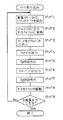
印字制御は、図9に示したフローチャート及び図10に示した説明図のように行われる。本実施例によるサーマルプリンタはラインプリンタであるから、1ライン分の印字は一度に行われる。前記のように1ライン分の印字処理は、タイマ1(71)またはタイマ2(72)が発生する内部割り込みによって起動される。本実施例では、タイマ1(71)は用紙P1側に印字する処理を起動するためのものであり、タイマ2(72)は用紙P2側に印字する処理を起動するためのものである。例として、用紙P1側に印字する場合の処理について説明する。
【0054】
まず、タイマ1(71)から割り込みが発生すると、CPU70は用紙P1に印字すべき画像データが格納された画像メモリ1から次に印字すべき1ラインのデータ82をCPU70内のラインメモリ73に読み込む。(ステップ1)
次にこれをCPU70内部で持つラインメモリ73のうち、用紙P1に対応する領域75に格納し、さらに用紙P2と、非印字領域に対応する領域74には、白画像データ76を格納する。(ステップ2)この場合、領域75が第1のデータ格納手段を構成し、領域74が第2のデータ格納手段を構成する。こうして構成した1ラインの画像データが、サーマルヘッド3に出力するフォーマットとなる。
【0055】
次にCPU70は、CLOCK信号を出力しながら、これに同期させて出力バッファ73のデータをシフトレジスタ64に出力する。これを出力バッファ73内のデータが全てシフトレジスタ64に転送されるまでくりかえす。(ステップ3)
次にCPU70は、LATCHパルスを出力する。このパルスによって、シフトレジスタ64に保持されていた画像データはラッチレジスタ63に転送される。(ステップ4)
次にCPU70は、ヘッド電源オン信号VpONを出力する。この信号によってVpSWはオンとなり、サーマルヘッド3はヘッド電源Vpに接続される。(ステップ5)
次にCPU70は、STROBE信号を出力する。この信号によってラッチレジスタ63に保持されたデータのうちアクティブなデータに対応した出力ドライバのスイッチング素子がオンし、これに接続された発熱体Dnに電流が供給され発熱する。前述のようにこのとき感熱用紙に画像が形成される。(ステップ6)次にCPU70は、VpON信号をオフし(ステップ7)、用紙1に対応する側の駆動モータを1ライン分駆動する。(ステップ8)以上の処理を全画像について繰り返し、ステップ9で全画像が出力されたかどうかを判断し、全画像出力後に処理を終了する。
【0056】
以上説明した処理は、用紙P1に対する処理であるが、用紙P2に対しても同様の処理を行う。ただし用紙P2に対する処理のうち、ステップ2のシフトレジスタに出力するフォーマットに変換する処理は、用紙P1と非印字部に対応する領域、即ち第2のデータ格納手段に白画像データを格納した後に、画像メモリ2(81)から用紙P2に印字すべき画像データを第1のデータ格納手段に格納することになる。またステップ8のモータの駆動も用紙P2に対応する駆動モータを駆動するようにする。
【0057】
ステップ2において、印字しない側の用紙に対応する領域には白画像データを設定しているが、印字しない側の用紙には一様の画像が形成されればよいとするならば、黒画像を設定するようにしてもよい。
【0058】
用紙P1に対する印字処理のタイミングと、用紙P2に対する印字処理のタイミングとは、同期させても、あるいは非同期で印字速度を変えてもよい。たとえば、用紙P1への印字速度を用紙P2への印字速度よりも早くしたい場合は、タイマ1の割り込み周期をタイマ2の割り込み周期よりも短く設定すればよい。このような動作が可能なのは、本発明によるサーマルプリンタが、紙送り手段を用紙に対して別々に持っているからである。
【0059】
印字処理の起動について言えば、前記実施例では二つのタイマによる割り込みによって起動する構成としたが、他の手段で起動するようにしてもよい。単なるソフトウエアによるループ処理は最も簡単な方法である。モータの駆動が終了したことによって割り込みが発生するような構造として、その割り込みで起動するように構成してもよい。起動手段は種々の構成が可能である。
【0060】
次に機構に関する他のいくつかの実施例について追加説明する。図1に示した実施例は、可動フレーム20を左端または右端のいずれか一方に寄せることによって用紙サイズを変更するようにしたものであったが、可動フレームは任意の位置に固定する構成であってもよい。
【0061】
図6はそのように構成した他の実施例に係るサーマルプリンタ100’の斜視図である。この実施例は、可動フレーム20を幅方向のいくつかの位置で固定できるようにしたものである。1g’は、ガイド壁1d’に設けられた係合用スリットで、幅方向に複数設けられている点が前記実施例とは異なっている。可動フレーム20は前記実施例と同様に規制片24a,24bを有し、この規制片が係合用スリット1g’にはまりこむことによって横方向への移動が固定される。係合用スリット1g’は複数設けられているので、そのスリットが存在する位置の望みの位置で可動フレーム20を固定することができる。この構成によれば、前記実施例で用いることのできる用紙の組合せよりも多くの組合せの用紙を用いることができ、用紙幅に対する自由度をいっそう増すことができる。
【0062】
また、この構成においても、可動フレーム20をより確実に固定するために、前記実施例と同様のストッパ兼導通部材(図示せず)を、本体フレーム1の側壁部との間に生じる空隙部C1’またはC2’に挿入するように構成してもよい。この場合、空隙部C1’またはC2’は、可動フレーム20が固定される複数の位置によってその幅が変化するから、幅を複数種類変えた複数のストッパ兼導通部材を用意しておく。このストッパ兼導通部材を挿入することによって、サーマルヘッド3を接地できることは、前記実施例と同様である。
【0063】
なお、可動フレーム20は、上記実施例のように離散的な位置において固定されるように構成する他に、幅方向の連続した任意の位置で固定するように構成してもよい。
【0064】
前記実施例では、用紙の端部を規制する規制片が可動フレームに設けられていたが、規制片は他の部位に設けてもよい。図7はそのように構成した他の実施例に係るサーマルプリンタ100”の斜視図である。この実施例では、ガイド壁1d”にスライド用の穴1hが設けられ、ここに規制片26a、26bがはまりこんで横方向にスライドできる構造になっている。規制片26a、26bは、図示しない固定機構によって、可動フレーム20”が固定された位置に応じた位置に固定される。
【0065】
可動フレーム20”には固定片27が設けられ、これがガイド壁1d”に設けられた係合用スリット1g”にはまりこむことによって可動フレーム20”が固定される。前記実施例と同様に、可動フレーム20”の固定をより確実にするために、ストッパ兼導通部材(図示せず)を本体フレームの側壁部との間に生じる空隙部に挿入するように構成してもよい。ストッパ兼導通部材の構成、及びそれがサーマルヘッドを接地する機能については、前記実施例と同様である。
【0066】
以上説明したサーマルプリンタでは、プラテンはローラ状で回転する構造であったが、プラテンは他の構造のものであってもよい。たとえば、サーマルヘッドに対向した面が凸形状で非円柱状であり回転しないものであっても、あるいは平面状のものであっても、本発明は適用可能である。
【0067】
【発明の効果】
以上説明したように、本発明に係る2連式サーマルプリンタでは、1個のサーマルヘッドに対して複数の用紙を対応させ、複数の用紙それぞれを移送する手段と、印字すべき用紙に対応する領域に印字すべきデータを設定する手段と、他の領域には発熱または非発熱のいずれかのデータを設定する手段を設けたので、用紙は独立して移送可能で、また印字すべき用紙に対応するデータのみをサーマルヘッドに設定することができるので、複数の用紙の各用紙への印字を独立して行うことができるという効果がある。
【0068】
また、本発明に係る2連式サーマルプリンタでは、本体フレームと、サーマルヘッドを保持するとともに本体フレームに対してスライド可能に取り付けられた可動フレームを設けたので、サーマルヘッドの位置は使用する用紙のサイズに合わせて移動可能であるため、使用する用紙のサイズを容易に変更することができ、これによってトータルのコストを低減することができるという効果がある。
【0069】
用紙を移送する手段は、各用紙に対応して設けられているため、各用紙に対する印字速度を変えることができ、これによって出力情報量に大きな差がある場合にも対応することができるという効果がある。
【図面の簡単な説明】
【図1】本発明に係るサーマルプリンタの一実施例を示す斜視図。
【図2】図1の実施例のサーマルプリンタにおけるサーマルヘッドをプラテンローラから離間した状態を示す断面側面図。
【図3】図1の実施例のサーマルプリンタにおけるサーマルヘッドをプラテンローラに押圧した状態を示す断面側面図。
【図4】可動フレームの具体例を示す斜視図。
【図5】可動フレームと本体フレームとの間に生じる空隙部に挿入されるストッパ兼導通部材の具体例を示す斜視図。
【図6】本発明に係るサーマルプリンタの第二の実施例を示す斜視図。
【図7】本発明に係るサーマルプリンタの第三の実施例を示す斜視図。
【図8】本発明に係るサーマルプリンタのサーマルヘッド周辺のブロック図。
【図9】本発明に係るサーマルプリンタの印字処理のフローチャート。
【図10】本発明に係るサーマルプリンタの印字データをヘッドに送る処理の説明図。
【符号の説明】
1 本体フレーム
1a,1b 側壁部
1c 支持壁
1d,1d’,1d” ガイド壁
1e,1f 側部全面壁
1g,1g’,1g” 係合用スリット
1h スライド用穴
2a,2b プラテンローラ
3 サーマルヘッド
3a 係合ピン
4 回動押圧部材(ヘッドアップダウン機構)
4a 押圧片
4b 操作レバー
4c 押上げ片
5 ヘッド支持軸
6a,6b ヘッド支持片
7 板バネ
8a,8b 回転軸
9a,9b 駆動モータ
10 ピン
11 支持ピン
20,20” 可動フレーム
21a,21b 保持片
22a,22b 貫通穴
23a,23b 係合穴
24a,24b 規制片
25a,25b ガイド片
26a,26b 規制片
27 固定片
30 ストッパ兼導通部材
31,32,33 切欠き
34,35 両翼片
36 接触片
37,38 係止片
41 コネクタ
42 検出器
50 板金
51 突起
61 発熱体ブロック
D1〜D864 個別の発熱体
62 出力ドライバ
64 シフトレジスタ
69 VpSW
70 CPU
71 タイマ1
72 タイマ2
73 ラインメモリ
74 用紙P2に対応する画像出力バッファ
75 用紙P1に対応する画像出力バッファ
76 白画像データ
80 画像メモリ1
81 画像メモリ2
82 画像の1ラインのデータ
100,100’,100” プリンタ[0001]
BACKGROUND OF THE INVENTION
The present invention relates to a printing apparatus and a multiple printing apparatus capable of printing on a plurality of sheets, and relates to a technique effective for use in, for example, a thermal printing apparatus (so-called thermal printer) having a thermal head.
[0002]
[Prior art]
Printers used as information output devices include an impact method such as a wire dot printer and a non-impact method. Further, non-impact printers include laser printers and thermal printers. Of these, impact type printers are noisy and have poor print quality, so in recent years non-impact type printers have become widely used. Among non-impact printers, thermal printers are suitable for miniaturization, and are therefore used in a wide range of fields.
[0003]
In particular, in a POS (Point Of Sales) terminal, it is necessary to print two sheets of output paper for a receipt to be handed over to a customer and output paper for a journal to be left as a copy of a store at the same time. The installed printer and the duplex printer having two heads have been put into practical use. However, since the cost of a print head is considerably high in a printer, a multiple printer having a head corresponding to each sheet can achieve downsizing to some extent, but a sufficient effect in terms of cost has not been obtained.
[0004]
In view of this, an invention relating to a double thermal printer has been proposed in which a thermal head is shared and two paper feed units are provided side by side with respect to the common thermal head, thereby reducing the size and improving the economy. (Patent No. 2819595).
[0005]
[Problems to be solved by the invention]
However, although the thermal printer according to the invention of the prior application has an advantage that it is an inexpensive device capable of simultaneously printing on two sheets of paper, the drive roller and the motor are one and the sheet feed mechanism is Since the guide part is fixed, the width of the paper to be printed is fixed, and the printing speed must be the same in the two systems, which reveals that there is a problem of low versatility. .
[0006]
In particular, in a POS terminal, there are many cases where it is desired to change the information to be output and the amount of the output paper for receipts to be handed over to customers and the output paper for journals to be kept at the store. Therefore, when the thermal printer according to the above-mentioned prior application is used for a POS terminal, two types of printers having different size ratios of the two sheets must be prepared, and a significant cost reduction cannot be achieved. .
[0007]
Moreover, since the thermal printer according to the above-mentioned prior application patent invention has one drive roller and one motor, the printing speed for two sheets cannot be changed. For this reason, it has been found that when the difference in the amount of output information is large, that is, when the amount of information is extremely different, there is a problem that the paper with the smaller amount of information has a larger margin and is wasted.
[0008]
An object of the present invention is to print on a plurality of thermal papers using one thermal head. 2 A continuous thermal printer that can print on each thermal paper independently of printing on other paper. 2 It is to provide a continuous thermal printer.
[0009]
In addition, the size of the paper used can be easily changed, which can reduce the total cost. 2 It is to provide a continuous thermal printer.
[0010]
Still another object of the present invention is to be able to change the printing speed for two sheets of paper, so that even if there is a large difference in the amount of output information, it is possible to cope with the sheet size ratio without changing much. It is to provide a continuous thermal printer.
[0011]
[Means for Solving the Problems]
The present invention has been made paying attention to the above-described problems, and includes a single thermal head in which a plurality of heat generating elements are arranged in a line and a plurality of portions corresponding to a plurality of thermal sheets can be set. , A paper feeding means capable of separately transferring the plurality of thermal papers, a line memory for storing data to be printed corresponding to the entire area of the thermal head, and a thermal head corresponding to the thermal paper to be printed. A first data storage means for storing data to be printed on the thermal paper to be printed in a part of the line memory corresponding to the part, and a heat generating element in the other part of the line memory is either heated or non-heated. And a second data storage means for storing the data to be set in one state, thereby constituting a double thermal printer.
[0012]
In this configuration, in order to move the thermal head so as to be compatible with thermal papers of various widths, a main body frame, a single thermal head in which a plurality of heating elements are arranged in a line, a thermal head, First and second platens arranged side by side in the line direction in which the heat generating elements are arranged, and two thermal sheets inserted between these platens and the thermal head, respectively. Paper feeding means that can be transferred separately, and a movable frame that holds the thermal head and is slidably mounted in a line direction in which the heating element is disposed, should be printed corresponding to the thermal head A line memory for storing data, and a line memo corresponding to a portion of the thermal head corresponding to the thermal paper to be printed out of the two thermal papers. The first data storage means for storing the data to be printed on the thermal paper to be printed in the part, and the data for setting the heat generating element in either the heat generation state or the non-heat generation state in the other part of the line memory. And a second data storage means for storing the two-way thermal printer.
[0013]
In this configuration, the paper feeding means is constituted by two drive motors provided corresponding to the respective thermal papers and two sets of gear reduction mechanisms that transmit the driving force of the drive motors, respectively. By providing drive motor control means for driving the drive motor on the side corresponding to the thermal paper to be printed, the feeding speed of each thermal paper can be set to a different speed.
[0014]
The movable frame can move in the width direction, but a head fixing means for fixing the movable frame at an arbitrary position in the line direction may be provided to ensure the fixing of the head.
[0015]
Further, if a pair of restricting pieces for restricting the end of the thermal sheet is provided at both ends of the movable frame to guide the sheet, it is not necessary to provide any other restricting member, and the configuration is simplified. Furthermore, a support wall may be provided between the first platen and the second platen, and the side surface of the support wall may be configured as a guide surface that regulates the other end of the thermal paper. However, the restricting member provided on the movable frame may be provided in another part of the printer, and the support wall and the guide surface provided between the platens may not be provided.
[0016]
DETAILED DESCRIPTION OF THE INVENTION
Preferred embodiments of the present invention will be described below with reference to the drawings.
[0017]
1 is a perspective view showing an embodiment of a thermal printer according to the present invention, FIG. 2 is a sectional side view showing a state in which the thermal head is separated from a platen roller, and FIG. 3 is a state in which the thermal head is pressed against the platen roller. FIG.
[0018]
In FIG. 1, 100 is a printer, 1 is a main body frame of the printer, 2a and 2b are platen rollers mounted on the front end of the
[0019]
As shown in FIG. 2, the
[0020]
Although not particularly limited, in this embodiment, a plurality of leaf springs 7 are fixed to the back surface of the
[0021]
Further, as shown in FIG. 2, a push-up piece 4c is provided at the lower end of the operation lever 4b, and an engagement pin 3a is provided on one side of the
[0022]
In this embodiment, as shown in FIG. 1, the
[0023]
[0024]
Note that a
[0025]
On the other hand, as shown in FIG. 1, the
[0026]
Next, the slide mechanism of the
[0027]
In this embodiment, a
[0028]
The pair of left and right head support pieces 6a and 6b that support the
[0029]
Further, the
[0030]
Specifically, when the
[0031]
Moreover, in this embodiment, the restricting
[0032]
Although not particularly limited, in this embodiment, a gap formed between the
[0033]
The substantially
[0034]
Of these, the locking
[0035]
The
[0036]
2 and 3,
[0037]
Next, a method for using the thermal printer of the above embodiment will be described.
[0038]
In the thermal printer of the embodiment, the
[0039]
Moreover, the thermal printer of this embodiment is provided with
[0040]
In the embodiment, by inserting the stopper / conduction member 30 into the gap C1 or C2 generated between the
[0041]
For example, in the embodiment shown in FIG. 1, when the
[0042]
In the embodiment, the driving force of the driving motor is transmitted to the platen roller and rotated. However, a paper feed roller may be provided separately from the platen roller.
[0043]
Next, the control circuit of the thermal printer according to the above embodiment will be described based on the block diagram of FIG.
[0044]
The
[0045]
The output of the shift register 64 is input to the
[0046]
The output of the
[0047]
In the
[0048]
The CPU 70 controls these thermal head peripheral circuits. The CPU 70 includes two timers 1 (71) and a timer 2 (72). These timers generate interrupts at regular intervals and are used to start the printing process. The CPU 70 also has a line memory 73 for storing data to be printed corresponding to the entire area of the thermal head. The line memory 73 stores data to be printed on the thermal paper to be printed. Divided into first data storage means (buffer) for storing data and other data storage means (buffer) for storing data for setting the heat generating element to either heat generation or non-heat generation in another part of the line memory Has been. Further, two image memories 1 (80) and 2 (81) are connected to the CPU 70. These image memories store image data to be printed on the two thermal papers P1 and P2.
[0049]
In the
[0050]
In the thermal printer according to the present invention, one
[0051]
Assume that two sheets P1 and P2 are arranged as shown in FIG. 8 with respect to the heating elements D1 to D864 constituting the
[0052]
Since the sheet can be arranged arbitrarily as described above, the correspondence between the two sheets P1 and P2 and the heating element Dm can be arbitrarily changed. Also, the size of the non-printing area, or whether or not it exists, can vary depending on the structure of the printer mechanism. The following description shows the arrangement shown in FIG. 8 as an example.
[0053]
The print control is performed as in the flowchart shown in FIG. 9 and the explanatory diagram shown in FIG. Since the thermal printer according to this embodiment is a line printer, printing for one line is performed at a time. As described above, the printing process for one line is started by an internal interrupt generated by the timer 1 (71) or the timer 2 (72). In this embodiment, the timer 1 (71) is for starting a process for printing on the paper P1 side, and the timer 2 (72) is for starting a process for printing on the paper P2 side. As an example, processing for printing on the paper P1 side will be described.
[0054]
First, when an interrupt is generated from the timer 1 (71), the CPU 70 reads one line of
Next, this is stored in the area 75 corresponding to the paper P1 in the line memory 73 held in the CPU 70, and further, the
[0055]
Next, the CPU 70 outputs the data of the output buffer 73 to the shift register 64 in synchronization with the output of the CLOCK signal. This is repeated until all the data in the output buffer 73 is transferred to the shift register 64. (Step 3)
Next, the CPU 70 outputs a LATCH pulse. With this pulse, the image data held in the shift register 64 is transferred to the
Next, the CPU 70 outputs a head power on signal VpON. By this signal, VpSW is turned on, and the
Next, the CPU 70 outputs a STROBE signal. By this signal, the switching element of the output driver corresponding to the active data among the data held in the
[0056]
The processing described above is processing for the paper P1, but the same processing is performed for the paper P2. However, the processing for converting to the format to be output to the shift register in
[0057]
In
[0058]
The timing of the printing process for the paper P1 and the timing of the printing process for the paper P2 may be synchronized or the printing speed may be changed asynchronously. For example, when the printing speed on the paper P1 is desired to be faster than the printing speed on the paper P2, the timer 1 interrupt cycle may be set shorter than the
[0059]
In regard to the activation of the printing process, in the above-described embodiment, it is configured to be activated by interruption by two timers, but it may be activated by other means. Simple software looping is the simplest method. As a structure in which an interrupt is generated when the driving of the motor is completed, the structure may be configured to start with the interrupt. The starting means can have various configurations.
[0060]
Next, some other embodiments related to the mechanism will be additionally described. In the embodiment shown in FIG. 1, the paper size is changed by moving the
[0061]
FIG. 6 is a perspective view of a
[0062]
Also in this configuration, in order to more reliably fix the
[0063]
The
[0064]
In the above-described embodiment, the restricting piece for restricting the edge of the sheet is provided on the movable frame. However, the restricting piece may be provided on another part. FIG. 7 is a perspective view of a
[0065]
The
[0066]
In the thermal printer described above, the platen has a structure that rotates in a roller shape, but the platen may have another structure. For example, the present invention can be applied even if the surface facing the thermal head is convex and non-cylindrical and does not rotate or is planar.
[0067]
【The invention's effect】
As described above, in the duplex thermal printer according to the present invention, a plurality of sheets are made to correspond to one thermal head, each of the plurality of sheets is transferred, and an area corresponding to the sheet to be printed. There is a means to set data to be printed on and a means to set either heat generation or non-heat generation data in other areas, so the paper can be transferred independently and corresponds to the paper to be printed. Since only the data to be set can be set in the thermal head, there is an effect that printing of each of a plurality of sheets can be performed independently.
[0068]
In the double thermal printer according to the present invention, the main body frame and the movable frame that holds the thermal head and is slidably attached to the main body frame are provided. Since the sheet can be moved in accordance with the size, the size of the paper to be used can be easily changed, which has the effect of reducing the total cost.
[0069]
Since the means for transporting the paper is provided corresponding to each paper, the printing speed for each paper can be changed, and this can cope with a case where there is a large difference in the amount of output information. There is.
[Brief description of the drawings]
FIG. 1 is a perspective view showing an embodiment of a thermal printer according to the present invention.
2 is a cross-sectional side view showing a state in which a thermal head in the thermal printer of the embodiment of FIG. 1 is separated from a platen roller.
3 is a cross-sectional side view showing a state in which a thermal head in the thermal printer of the embodiment of FIG. 1 is pressed against a platen roller.
FIG. 4 is a perspective view showing a specific example of a movable frame.
FIG. 5 is a perspective view showing a specific example of a stopper / conduction member inserted into a gap formed between the movable frame and the main body frame.
FIG. 6 is a perspective view showing a second embodiment of the thermal printer according to the present invention.
FIG. 7 is a perspective view showing a third embodiment of the thermal printer according to the present invention.
FIG. 8 is a block diagram around the thermal head of the thermal printer according to the present invention.
FIG. 9 is a flowchart of print processing of the thermal printer according to the present invention.
FIG. 10 is an explanatory diagram of processing for sending print data of the thermal printer according to the present invention to the head.
[Explanation of symbols]
1 Body frame
1a, 1b side wall
1c Support wall
1d, 1d ', 1d "guide wall
1e, 1f Side wall
1g, 1g ', 1g "slit for engagement
1h Slide hole
2a, 2b Platen roller
3 Thermal head
3a engaging pin
4 Rotating pressing member (head up / down mechanism)
4a Pressing piece
4b Operation lever
4c Push-up piece
5 Head support shaft
6a, 6b Head support piece
7 leaf spring
8a, 8b Rotating shaft
9a, 9b Drive motor
10 pins
11 Support pin
20,20 "movable frame
21a, 21b Holding piece
22a, 22b Through hole
23a, 23b engagement hole
24a, 24b Restriction piece
25a, 25b Guide piece
26a, 26b Restriction piece
27 Fixed piece
30 Stopper and conductive member
31, 32, 33 Notch
34, 35 both wing pieces
36 Contact piece
37, 38 Locking piece
41 connector
42 Detector
50 sheet metal
51 protrusion
61 Heating element block
D1 to D864 Individual heating element
62 Output driver
64 shift register
69 VpSW
70 CPU
71 Timer 1
72
73 line memory
74 Image output buffer for paper P2
75 Image output buffer for paper P1
76 White image data
80 Image memory 1
81
82 One line of data
100, 100 ', 100 "printer
Claims (5)
複数の発熱要素がライン状に配設された1個のサーマルヘッドと、
サーマルヘッドと並設され、前記発熱要素が配設されたライン方向に互いに並設された第1および第2のプラテンと、
これらのプラテンと前記サーマルヘッドとの間にそれぞれ挿入された2枚の感熱用紙を別々に移送可能な紙送り手段と、
前記サーマルヘッドを保持するとともに前記発熱要素が配設されたライン方向にスライド可能に取り付けられた可動フレームと、
前記サーマルヘッドに対応して印字すべきデータを格納するラインメモリと、
前記2枚の感熱用紙のうち、印字すべき感熱用紙に対応する前記サーマルヘッドの部位に対応したラインメモリの部位に、印字すべき感熱用紙に印字すべきデータを格納する第1のデータ格納手段と、
前記ラインメモリの他の部位に、発熱要素を発熱または非発熱のいずれか一方の状態にするデータを格納する第2のデータ格納手段とを備えたことを特徴とする2連式サーマルプリンタ。Body frame,
One thermal head in which a plurality of heating elements are arranged in a line;
A first platen and a second platen arranged in parallel with each other in a line direction in which the heat generating element is disposed;
A paper feeding means capable of separately transferring two thermal papers inserted between the platen and the thermal head;
A movable frame that holds the thermal head and is slidably mounted in a line direction in which the heating element is disposed;
A line memory for storing data to be printed corresponding to the thermal head;
A first data storage means for storing data to be printed on the thermal paper to be printed in a portion of the line memory corresponding to the portion of the thermal head corresponding to the thermal paper to be printed, of the two thermal papers. When,
A duplex thermal printer, comprising: a second data storage means for storing data for setting the heat generating element in either the heat generation state or the non-heat generation state in another part of the line memory.
該駆動モータの駆動力をそれぞれ伝達する2組の歯車減速機構とにより構成され、
更に、前記印字すべき感熱用紙に対応する側の駆動モータを駆動する駆動モータ制御手段を備えたことを特徴とする請求項1に記載の2連式サーマルプリンタ。The paper feeding means includes two drive motors provided corresponding to the thermal papers,
And two sets of gear reduction mechanisms that transmit the driving force of the drive motor,
2. The dual thermal printer according to claim 1 , further comprising drive motor control means for driving a drive motor on a side corresponding to the thermal paper to be printed.
Priority Applications (1)
| Application Number | Priority Date | Filing Date | Title |
|---|---|---|---|
| JP2000011602A JP4091230B2 (en) | 2000-01-20 | 2000-01-20 | Double thermal printer |
Applications Claiming Priority (1)
| Application Number | Priority Date | Filing Date | Title |
|---|---|---|---|
| JP2000011602A JP4091230B2 (en) | 2000-01-20 | 2000-01-20 | Double thermal printer |
Publications (3)
| Publication Number | Publication Date |
|---|---|
| JP2001199115A JP2001199115A (en) | 2001-07-24 |
| JP2001199115A5 JP2001199115A5 (en) | 2004-11-18 |
| JP4091230B2 true JP4091230B2 (en) | 2008-05-28 |
Family
ID=18539446
Family Applications (1)
| Application Number | Title | Priority Date | Filing Date |
|---|---|---|---|
| JP2000011602A Expired - Fee Related JP4091230B2 (en) | 2000-01-20 | 2000-01-20 | Double thermal printer |
Country Status (1)
| Country | Link |
|---|---|
| JP (1) | JP4091230B2 (en) |
-
2000
- 2000-01-20 JP JP2000011602A patent/JP4091230B2/en not_active Expired - Fee Related
Also Published As
| Publication number | Publication date |
|---|---|
| JP2001199115A (en) | 2001-07-24 |
Similar Documents
| Publication | Publication Date | Title |
|---|---|---|
| US4184063A (en) | Thermal printer write head assembly | |
| EP0661165B1 (en) | Recording apparatus | |
| JP4091229B2 (en) | Double thermal printer | |
| JP4091230B2 (en) | Double thermal printer | |
| US4256408A (en) | Dot matrix print head | |
| EP1063094B1 (en) | Printer with driving mechanism by single motor for both sheet transferring mechanism and sheet cutting mechanism | |
| JP3691324B2 (en) | Double thermal printer | |
| US4776715A (en) | Head rotating mechanism for a printer | |
| JPH11245477A (en) | Thermal printer | |
| US6262754B1 (en) | Dual type thermal printer | |
| JP2000108390A (en) | Thermal transfer printer | |
| JP2794739B2 (en) | Thermal printer and thermal printing method | |
| JP2001310494A (en) | Line thermal printer | |
| JP2661673B2 (en) | Image forming device | |
| JPS6392465A (en) | Thermal transfer printer | |
| JP3866961B2 (en) | Line thermal printer | |
| JPS5939561A (en) | Heat sensitive printer | |
| JP3139630B2 (en) | Image input / output device | |
| JP2001354338A (en) | Sheet carrying mechanism of printer | |
| JP2000229428A (en) | Thermal printer | |
| JP3158752B2 (en) | Ink ribbon cassette and printing device | |
| JP2001199119A (en) | Twin thermal printer | |
| JP2002187301A (en) | Method and structure for adjusting angle of heating element of printer | |
| KR20010001955U (en) | Platen adjuster of printer for used cash register | |
| JPH0671808B2 (en) | Paper feeder for printer |
Legal Events
| Date | Code | Title | Description |
|---|---|---|---|
| A521 | Written amendment |
Free format text: JAPANESE INTERMEDIATE CODE: A523 Effective date: 20031201 |
|
| A621 | Written request for application examination |
Effective date: 20031201 Free format text: JAPANESE INTERMEDIATE CODE: A621 |
|
| RD01 | Notification of change of attorney |
Effective date: 20040302 Free format text: JAPANESE INTERMEDIATE CODE: A7421 |
|
| A131 | Notification of reasons for refusal |
Free format text: JAPANESE INTERMEDIATE CODE: A131 Effective date: 20071120 |
|
| A521 | Written amendment |
Effective date: 20071210 Free format text: JAPANESE INTERMEDIATE CODE: A523 |
|
| A131 | Notification of reasons for refusal |
Effective date: 20080115 Free format text: JAPANESE INTERMEDIATE CODE: A131 |
|
| A521 | Written amendment |
Effective date: 20080125 Free format text: JAPANESE INTERMEDIATE CODE: A523 |
|
| TRDD | Decision of grant or rejection written | ||
| A01 | Written decision to grant a patent or to grant a registration (utility model) |
Free format text: JAPANESE INTERMEDIATE CODE: A01 Effective date: 20080226 |
|
| A61 | First payment of annual fees (during grant procedure) |
Effective date: 20080228 Free format text: JAPANESE INTERMEDIATE CODE: A61 |
|
| R150 | Certificate of patent (=grant) or registration of utility model |
Free format text: JAPANESE INTERMEDIATE CODE: R150 |
|
| FPAY | Renewal fee payment (prs date is renewal date of database) |
Free format text: PAYMENT UNTIL: 20110307 Year of fee payment: 3 |
|
| RD01 | Notification of change of attorney |
Free format text: JAPANESE INTERMEDIATE CODE: A7421 Effective date: 20091108 |
|
| FPAY | Renewal fee payment (prs date is renewal date of database) |
Year of fee payment: 3 Free format text: PAYMENT UNTIL: 20110307 |
|
| RD03 | Notification of appointment of power of attorney |
Free format text: JAPANESE INTERMEDIATE CODE: R3D03 |
|
| FPAY | Renewal fee payment (prs date is renewal date of database) |
Free format text: PAYMENT UNTIL: 20110307 Year of fee payment: 3 |
|
| FPAY | Renewal fee payment (prs date is renewal date of database) |
Year of fee payment: 4 Free format text: PAYMENT UNTIL: 20120307 |
|
| LAPS | Cancellation because of no payment of annual fees |