JP4091121B2 - Bending center and method for introducing metal sheet material part into bending center of bending center - Google Patents
Bending center and method for introducing metal sheet material part into bending center of bending center Download PDFInfo
- Publication number
- JP4091121B2 JP4091121B2 JP51519198A JP51519198A JP4091121B2 JP 4091121 B2 JP4091121 B2 JP 4091121B2 JP 51519198 A JP51519198 A JP 51519198A JP 51519198 A JP51519198 A JP 51519198A JP 4091121 B2 JP4091121 B2 JP 4091121B2
- Authority
- JP
- Japan
- Prior art keywords
- sheet material
- metal sheet
- sensor
- material portion
- manipulator
- Prior art date
- Legal status (The legal status is an assumption and is not a legal conclusion. Google has not performed a legal analysis and makes no representation as to the accuracy of the status listed.)
- Expired - Fee Related
Links
Images


Classifications
-
- B—PERFORMING OPERATIONS; TRANSPORTING
- B21—MECHANICAL METAL-WORKING WITHOUT ESSENTIALLY REMOVING MATERIAL; PUNCHING METAL
- B21D—WORKING OR PROCESSING OF SHEET METAL OR METAL TUBES, RODS OR PROFILES WITHOUT ESSENTIALLY REMOVING MATERIAL; PUNCHING METAL
- B21D5/00—Bending sheet metal along straight lines, e.g. to form simple curves
- B21D5/04—Bending sheet metal along straight lines, e.g. to form simple curves on brakes making use of clamping means on one side of the work
-
- B—PERFORMING OPERATIONS; TRANSPORTING
- B21—MECHANICAL METAL-WORKING WITHOUT ESSENTIALLY REMOVING MATERIAL; PUNCHING METAL
- B21D—WORKING OR PROCESSING OF SHEET METAL OR METAL TUBES, RODS OR PROFILES WITHOUT ESSENTIALLY REMOVING MATERIAL; PUNCHING METAL
- B21D43/00—Feeding, positioning or storing devices combined with, or arranged in, or specially adapted for use in connection with, apparatus for working or processing sheet metal, metal tubes or metal profiles; Associations therewith of cutting devices
- B21D43/003—Positioning devices
-
- B—PERFORMING OPERATIONS; TRANSPORTING
- B21—MECHANICAL METAL-WORKING WITHOUT ESSENTIALLY REMOVING MATERIAL; PUNCHING METAL
- B21D—WORKING OR PROCESSING OF SHEET METAL OR METAL TUBES, RODS OR PROFILES WITHOUT ESSENTIALLY REMOVING MATERIAL; PUNCHING METAL
- B21D43/00—Feeding, positioning or storing devices combined with, or arranged in, or specially adapted for use in connection with, apparatus for working or processing sheet metal, metal tubes or metal profiles; Associations therewith of cutting devices
- B21D43/02—Advancing work in relation to the stroke of the die or tool
- B21D43/04—Advancing work in relation to the stroke of the die or tool by means in mechanical engagement with the work
- B21D43/10—Advancing work in relation to the stroke of the die or tool by means in mechanical engagement with the work by grippers
- B21D43/105—Manipulators, i.e. mechanical arms carrying a gripper element having several degrees of freedom
-
- B—PERFORMING OPERATIONS; TRANSPORTING
- B21—MECHANICAL METAL-WORKING WITHOUT ESSENTIALLY REMOVING MATERIAL; PUNCHING METAL
- B21D—WORKING OR PROCESSING OF SHEET METAL OR METAL TUBES, RODS OR PROFILES WITHOUT ESSENTIALLY REMOVING MATERIAL; PUNCHING METAL
- B21D43/00—Feeding, positioning or storing devices combined with, or arranged in, or specially adapted for use in connection with, apparatus for working or processing sheet metal, metal tubes or metal profiles; Associations therewith of cutting devices
- B21D43/02—Advancing work in relation to the stroke of the die or tool
- B21D43/04—Advancing work in relation to the stroke of the die or tool by means in mechanical engagement with the work
- B21D43/14—Advancing work in relation to the stroke of the die or tool by means in mechanical engagement with the work by turning devices, e.g. turn-tables
-
- B—PERFORMING OPERATIONS; TRANSPORTING
- B21—MECHANICAL METAL-WORKING WITHOUT ESSENTIALLY REMOVING MATERIAL; PUNCHING METAL
- B21D—WORKING OR PROCESSING OF SHEET METAL OR METAL TUBES, RODS OR PROFILES WITHOUT ESSENTIALLY REMOVING MATERIAL; PUNCHING METAL
- B21D5/00—Bending sheet metal along straight lines, e.g. to form simple curves
- B21D5/002—Positioning devices
-
- B—PERFORMING OPERATIONS; TRANSPORTING
- B23—MACHINE TOOLS; METAL-WORKING NOT OTHERWISE PROVIDED FOR
- B23Q—DETAILS, COMPONENTS, OR ACCESSORIES FOR MACHINE TOOLS, e.g. ARRANGEMENTS FOR COPYING OR CONTROLLING; MACHINE TOOLS IN GENERAL CHARACTERISED BY THE CONSTRUCTION OF PARTICULAR DETAILS OR COMPONENTS; COMBINATIONS OR ASSOCIATIONS OF METAL-WORKING MACHINES, NOT DIRECTED TO A PARTICULAR RESULT
- B23Q17/00—Arrangements for observing, indicating or measuring on machine tools
- B23Q17/22—Arrangements for observing, indicating or measuring on machine tools for indicating or measuring existing or desired position of tool or work
- B23Q17/2233—Arrangements for observing, indicating or measuring on machine tools for indicating or measuring existing or desired position of tool or work for adjusting the tool relative to the workpiece
-
- B—PERFORMING OPERATIONS; TRANSPORTING
- B23—MACHINE TOOLS; METAL-WORKING NOT OTHERWISE PROVIDED FOR
- B23Q—DETAILS, COMPONENTS, OR ACCESSORIES FOR MACHINE TOOLS, e.g. ARRANGEMENTS FOR COPYING OR CONTROLLING; MACHINE TOOLS IN GENERAL CHARACTERISED BY THE CONSTRUCTION OF PARTICULAR DETAILS OR COMPONENTS; COMBINATIONS OR ASSOCIATIONS OF METAL-WORKING MACHINES, NOT DIRECTED TO A PARTICULAR RESULT
- B23Q17/00—Arrangements for observing, indicating or measuring on machine tools
- B23Q17/24—Arrangements for observing, indicating or measuring on machine tools using optics or electromagnetic waves
Landscapes
- Engineering & Computer Science (AREA)
- Mechanical Engineering (AREA)
- Physics & Mathematics (AREA)
- Optics & Photonics (AREA)
- Bending Of Plates, Rods, And Pipes (AREA)
- Folding Of Thin Sheet-Like Materials, Special Discharging Devices, And Others (AREA)
- Polymers With Sulfur, Phosphorus Or Metals In The Main Chain (AREA)
- Materials For Medical Uses (AREA)
- Organic Low-Molecular-Weight Compounds And Preparation Thereof (AREA)
Abstract
Description
本発明は曲げ加工ユニットと、挿入されるべき金属シート材部分を受け取るための送りテーブルを備えた充填装置と、送りテーブル上の金属シート材部分を把持して第1の方向に移動させ、第1の方向を横切って延びる第2の方向に移動させ、これら第1および第2の方向により画定される平面に対し直角をなす回転軸回りに回転させるマニピュレータ装置とを具備した曲げ加工センタに関する。
この形式の曲げ加工センタは当該技術分野の現状から見て公知である。これらの曲げ加工センタ問題点はまず初めに、曲げ加工センタに供給された金属シート材部分を例えば停止手段を用いて正確に位置決めする必要があり、金属シート材部分が正確に位置決めされて初めてマニピュレータ装置は金属シート材部分を取り扱うことができ、それにより正確な位置から始まって、金属シート材部分が曲げ加工ユニットの正確な挿入位置に移動される。
このような正確な挿入位置に移動させるようにすると、時間がかかり、特に自動供給の場合に一方では位置決めするのにかなりの時間を必要とし、他方では結果として金属シート材部分を除去せしめあるいは損傷せしめるエラーが生じる。
したがって、本発明の目的は一般的な形式の曲げ加工センタを改良して金属シート材部分の取り扱いにおいてエラーをできるだけなくし、充填時間をできるだけ短くすることにある。
この目的は本発明によれば、冒頭で述べた形式の曲げ加工センタにおいて、充填装置が曲げ加工ユニットへの定められた挿入位置に対する金属シート材部分の位置を判別するセンサと、金属シート材部分を取り扱うマニピュレータ装置を制御するための制御装置とを有し、制御装置はセンサにより判別された金属シート材部の位置に基づき第1の方向および第2の方向への移動と、回転軸回りの回転とについてマニピュレータ装置を制御してマニピュレータ装置が金属シート材部分を、正確に定められた挿入位置において曲げ加工ユニットに挿入するようにした曲げ加工センタによって達成される。
本発明による解決策の利点は、マニピュレータ装置が、従来のように金属シート材部分を曲げ加工ユニットに挿入するのではなく、しかし、同時に、大まかな位置決めに次いで、送りテーブルの領域において金属シート材部分を正確に位置決めするようもっぱら作用することにある。ここで、センサによる金属シート材部分の位置の判別はこの正確な位置決めに先立って行われる。
これは充填時間をかなり短縮することができることを意味し、というのはマニピュレータ装置が金属シート材部分を取り扱うのに先立って時間のかかる金属シート材部分の正確な位置決めが行われないからである。
さらに、初期位置決めエラーの場合にマニピュレータ装置による金属シート材部分の取り扱いにエラーが生ずるのが阻止される。何故ならば、マニピュレータ装置は金属シート材部分の正確な初期位置から手順を開始せず、しかしながらあらゆる場合において金属シート材部分の位置をセンサにより判別し、次いで正確な挿入位置に到達するようにマニピュレータ装置が取り扱うことにより金属シート材部分の位置が修正される。
原則、1つまたは複数のセンサを配置してマニピュレータ装置が金属シート材部分を、センサを通過するよう移動させるときに、これらセンサにより金属シート材部分の測定を行うようにすることもできる。しかしながら、算出時間のために、マニピュレータ装置が金属シート材部分を取り扱うのに先立って制御装置が金属シート材部分の位置を確認するのが有利である。この場合の利点は搬送座標の算出によるあらゆる遅れが必要でなくなり、しかしながら取り扱いが開始されるのに先立ってこれら搬送座標を利用することができる。
金属シート材部分の位置をできるだけ少数のセンサにより判別可能にするために、好ましくはセンサを第1および第2の方向に移動可能にして第1の方向における金属シート材部分の位置を確認できるようにするだけでなく第2の方向における金属シート材部分の位置、およびセンサに対する金属シート材部分の回転方向における金属シート材部分の位置も確認できるようにするのが好ましい。
この目的ため、原則、センサを移動せしめる別の装置を設けることができる。しかしながら、センサをマニピュレータ装置上に配置してマニピュレータ装置より少なくとも一方向に移動可能にすると、特に有利である。この方向に関するセンサの位置制御される軸方向移動を省略することができ、この方向に関するマニピュレータ装置の軸方向移動はあらゆる場合に生ずるが、このマニピュレータ装置の軸方向移動を利用することができる。
金属シート材部分は通常、曲げ加工ユニットに複数の位置において挿入されなければならないので、好ましくはマニピュレータ装置に、送りテーブル上の金属シート材部分を把持してこの金属シート材部分を第1の方向に移動させる第1マニピュレータと、金属シート材部分が第1の方向の移動した後に金属シート材部分を引き継いで第2の方向に移動させると共に、回転軸回りに回転させる第2マニピュレータとが設けられる。金属シート材部分の取り扱い機能を第1マニピュレータと第2マニピュレータとに分割した結果、同時に両方が動作することができ、例えば第1マニピュレータが金属シート材部分の方向に移動し、このとき第2マニピュレータは先に供給された金属シート材部分を異なる挿入位置において曲げ加工ユニットに挿入する。
原則、第1マニピュレータは金属シート材部分をどのように把持してもよい。しかしながら、第1マニピュレータが概ね第1の方向に延びる長手方向側部において金属シート材部分を把持するようにすると特に有利であることが判明している。何故ならば、中央領域において金属シート材部分を把持して回転軸回りに適当に回転させるようになっている第2マニピュレータまで金属シート材部分を移動させるのが特に容易になるからである。
個々の実施態様に関する上記説明では、センサの配置について何ら詳細に述べられていない。例えば、好ましい一実施態様においてセンサは金属シート材部分のセンサに対面する一縁部領域の複数の位置を検出するようにされ、複数の縁部領域を検出せしめられず、しかしながら一縁部領域の複数の位置から金属シート材部分の位置を完全に判別することができる。
センサを第1マニピュレータ上に配置してこの第1マニピュレータより第1の方向に移動可能にすると、特に好ましい。この解決策は第1マニピュレータの移動時に、さらに、第2マニピュレータの場合よりもセンサに必要な移動時に、概ね長い時間にわたって考慮することができる限り好ましい。何故ならば、第2マニピュレータ金属シート材部分を様々な位置において曲げ加工ユニットに供給しなければならず、これに対し第1マニピュレータは金属シート材部分を送りテーブルから第2マニピュレータの作動領域内に一度だけ移動させるのみであるからである。
この解決策によれば、第1の方向におけるセンサの可動性が達成され、しかしながら第2の方向への移動は達成されない。このため、センサが第2の方向に移動可能であるようにセンサを第1マニピュレータ上に保持さるのが好ましい。この追加の可動性により、センサが互いに直角をなす二方向に移動可能となり、したがって金属シート材部分の位置を完全に検出することができる。
この目的のために、第2の方向におけるセンサの位置を制御装置により制御可能にして第1の方向を横切る方向すなわち第2の方向にセンサが移動する第1の方向の位置を検出可能にするのが好ましい。制御装置はしたがって金属シート材部分の特定の位置に近づき、かつセンサによりこれら位置を測定してこれらの測定結果から金属シート材部分の位置が判別されるように位置する。なお、金属シート材部分の形状は制御装置に入力されている。
上記説明では、第1マニピュレータ上におけるセンサの配置について何ら詳細に述べられていない。送りテーブルに対面する第1マニピュレータの側部上にセンサを配置すると、特に好ましい。何故ならば、第1マニピュレータが金属シート材部分を把持すべく送りテーブルに向け移動する間、マニピュレータ装置が金属シート材部分を把持する位置に位置する前にセンサが金属シート材部分上を移動可能となるからである。この場合、これは次のことを意味する。すなわち、センサがマニピュレータ装置よりも前に配置され、あらゆる場合において必要なマニピュレータ装置の送りテーブルへの移動を、第1の方向へのセンサの必要な移動を得るのに用いることができ、同時に第1のセンサにより行われる測定が第1マニピュレータの移動に用いられる期間と干渉しない。
個々の実施態様に関する上記説明では、センサの構成について何ら詳細に述べられていない。例えば、センサにより金属シート材部分のマークを認識し、この認識されたマークに基づいて金属シート材部分の位置を検出するのが好ましい。しかしながら、センサを、金属シート材部分の縁部を検出するセンサから形成すると、特に好ましい。何故ならば、この場合、金属シート材部分にすでに形成されている縁部を金属シート材部分の位置を判別するために用いることができるので、マークの別個の付与が不必要であるからである。
特に好ましい解決策では、金属シート材部分の形状に関するデータに基づきセンサを制御装置により位置決め可能にしてセンサが金属シート材部分の切り込みの縁部を検出するようにしている。この解決策の大きな利点は金属シート材部分に高精度で設けられた切り込みが曲げ加工ユニットへの金属シート材部分の挿入位置のための基準点を正確に表しているということである。
個々の実施態様に関する上記説明の範囲において、センサ自体の構成について何ら詳細に述べられていない。例えば有利な一実施態様では、センサがフォーク状部材内に配置された光遮断式センサから形成され、縁部を検出する間、金属シート材部分がフォーク状部材と係合するようにされる。このため、縁部位置を特に簡単にかつ正確に検出することができる。何故ならば、フォーク状部材により、金属シート材部分上方および下方にできるだけ小さな距離を隔てて光遮断式センサの発信要素および受信要素を位置決めすることができるからである。
さらに、上述の目的は本発明によれば、金属シート材部分を曲げ加工センタの曲げ加工ユニットに導入する方法であって、送りテーブル上において金属シート材部分がマニピュレータ装置により把持されて第1の方向と、この第1の方向を横切って延びる第2の方向とに移動され、回転軸回りの複数の回転位置において曲げ加工ユニットに挿入されるようになっており、この回転軸が第1および第2の方向により画定される平面に対し直角に延びている方法において、曲げ加工ユニットへの定められた挿入位置に対する金属シート材部分の相対位置をセンサにより検出し、金属シート材部分を取り扱うマニピュレータ装置に、測定された位置座標に基づき第1および第2の方向に移動させると共に回転軸回りに回転させて金属シート材部分が定められた挿入位置において曲げ加工ユニットに供給されるようにした方法により達成される。
本発明による方法の利点は同様に以下の通りである。すなわち、大まかな位置決めから始まって、あらゆる場合において必要な金属シート材部分の曲げ加工ユニットへの挿入のための取り扱いが、金属シート材部分を正確に位置決めするのと同時に用いられ、それにより従来技術によりあらかじめ行なわれる正確な位置決めを省略することができ、金属シート材部分を確実に取り扱いつつ充填時間をかなり短縮することができる。
上記説明では、金属シート材部分の位置座標の測定位置について何ら詳細に述べられていない。原則、第1の方向における金属シート材部分の移動が終了するのに先立って第1の方向における金属シート材部分の位置座標の測定が終了するようにし、それによりこの移動時に金属シート材部分の位置を考慮して修正できるようにすれば十分である。
さらに、第2の方向における位置座標の修正がこの方向における移動により行われ、同時に第2の方向に対するあらゆる回転が修正されるので、第2の方向における移動が終了するのに先立って第2の方向における金属シート材部分の測定と、第2の方向に対する回転動作の測定とが終了するようにすれば十分である。
しかしながら、特に好ましい解決策によれば、送りテーブルの領域において位置座標の判別が行われる。
これに関し、マニピュレータによる取り扱いに先立って金属シート材部分の位置を測定するようにすると特に好ましい。何故ならば、算出時間を、マニピュレータの制御パラメータを画定するのに用いることができ、マニピュレータによる移動がマニピュレータの位置の測定と必要な算出時間とにより阻害されないからである。
位置座標の測定時にセンサが金属シート材部分に対し移動されるときに位置座標の測定が行われるようにし、それにより金属シート材部分の位置座標を、金属シート材部分を移動させることなく簡単な方法でもって測定するすると特に好ましい。
センサを様々な方法により移動させることができる。例えば、センサのために設けられた駆動装置により行うことができる。特に有利な解決策によれば、位置座標を測定する間、センサはマニピュレータ装置により少なくとも一方向に移動され、それにより同時にマニピュレータ装置の数値制御された移動をセンサの移動のために用いることができる。
本発明による解決策の変更例では、第1の方向におけるセンサの位置をマニピュレータ装置に位置から判別してあらゆる場合において必要なマニピュレータ装置の移動のための位置判別を、同時にセンサの位置判別のために用いることができるようにすると特に有利である。
さらに、マニピュレータ装置によりセンサが一方向に移動されるこのような有利な実施態様において、センサが自動制御されて第2の方向に移動され、この追加の移動時にマニピュレータ装置の残りの動作に影響を与えないようにされる。
充填時間をできるだけ短くするために、金属シート材部分を第1マニピュレータにより送りテーブルから第1の方向に遠ざけ、第2マニピュレータにより第2の方向に移動させて回転軸回りに回転させるようにすると、特に有利である。このように金属シート材部分の取り扱いを分割するのは好ましく、何故ならば、曲げ加工ユニットへの金属シート材部分の挿入は通常、複数の工程を必要とし、このため時間がかかり、第1マニピュレータにより把持されるべき金属シート材部分のためにこの時間を用いることができる。
同時に、第1マニピュレータをセンサを第1の方向に移動させるのに用い、センサの一部は好ましくは第1マニピュレータに対し移動可能であり、さらに、第2の方向に制御されつつ移動可能である。
上記説明では、位置座標の測定について何ら詳細に述べられていない。例えば、有利な解決策によれば、位置座標の測定は金属シート材部分の縁部位置を測定することにより行われ、好ましくは金属シート材部分の切り込みが検出される。何故ならば、これらの切り込みは定められた位置において金属シート材部分に形成され、このため金属シート材部分の位置座標を、特に曲げ加工センタにおける金属シート材部分の曲げ加工に関して、正確に検出することができる。
本発明のさらなる特徴および利点は一実施態様を表す以下の記載および添付図面により明らかにされる。
添付図面において、
図1は本発明の曲げ加工センタの斜視図、
図2は図1の矢印Aの方向からみた曲げ加工センタの平面図、
図3は図2の線3−3に沿ってみた断面図、
図4は図2の線4−4に沿ってみた断面図である。
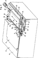
図1に示される本発明の曲げ加工センタの実施態様は全体が10でもって示される曲げ加工ユニットと、全体が12でもって示される充填装置とを具備する。図2から明らかなように、この充填装置12は曲げ加工ユニット10、特に鎖線で示される曲げ加工縁部16により代表される曲げ加工装置に金属シート材部分14を挿入位置において供給することができ、この挿入位置は例えば金属シート材部分14の縁部領域18a−18dが金属シート材部分14の形状により定まる所定の曲げ加工線20a−20dに沿って折り曲げ加工されるように画定される。したがって、金属シート材部分14の挿入位置は例えば、金属シート材部分14のすべての曲げ加工線20a−20dが曲げ加工ユニット10の曲げ加工縁部16に正確に合致して位置するように画定される。
この目的のために本発明の充填装置12は送りテーブル22を具備し、この送りテーブル22上に、手作業または追加の送り装置により金属シート材部分14を置くことができる。この場合、全体が30でもって示されるマニピュレータ装置の把持領域において金属シート材部分14の大まかな位置決めを行うのが好ましい。
このマニピュレータ装置30は第1マニピュレータ32を具備し、この第1マニピュレータは図1および図2に示されるようにX方向に、金属シート材部分14を送りテーブル22から第2マニピュレータ36の作動領域34内に移動せしめるよう作動する。第2マニピュレータ36は金属シート材部分14を把持した後にY方向に移動せしめ、X方向とY方向とにより画定される平面に対し直角をなす回転軸D回りに金属シート材部分14を回転せしめる。このとき、金属シート材部分14はX方向とY方向により画定される平面内に拡がっている。なお、Y方向は好ましくはX方向に対し直角をなして延びる。
第1および第2マニピュレータは共に、全体が38でもって示される制御装置により制御されるが、この制御装置38内には金属シート材部分14および曲げ加工線20a−20bの形状と、曲げ加工ユニット10の曲げ加工縁部16の座標とが記憶されている。
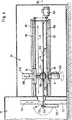
図3に示されるように、第1マニピュレータ32はマニピュレータキャリッジ42を具備し、このマニピュレータキャリッジ42はX方向にかつ互いに平行に延びる2つの直線案内手段44,46により案内され、例えばねじ山付きスピンドル48によりX方向に沿って位置決めされる。このスピンドル48は制御装置38による数値制御でもってスピンドル駆動装置50により駆動される。
直線案内手段44,46はマニピュレータキャリッジ42と共に充填装置12の長手方向に延びる側部52に配置され、したがって送りテーブル22に沿って移動することができる。
マニピュレータキャリッジ42はその送りテーブル22に面する側に、複数の把持トング54a−54cを有し、これら把持トング54a−54cは金属シート材部分14を、マニピュレータキャリッジ42に対面しかつ概ねX方向に延びる縁部領域56において把持することができる。
金属シート材部分14は基本的に送りテーブル22の表面58上に配置されており、しかしながらこの表面58は金属シート材部分14の縁部領域56までは延びていない。むしろ、縁部領域56はブラシ60の領域により支持されており、このため把持トング54a−54cは妨害されることなくアクセスすることができる。
第2マニピュレータの作動範囲34と逆方向を向きかつ送りテーブル22に面する第1マニピュレータ32のマニピュレータキャリッジ42の端部には発信要素62と受信要素64とを具備したセンサ66が支持されており、このセンサ66は例えば遮光の原理に基づいて作動する。発信要素62は全体が72でもって示されるフォーク状センサ部材の第1フィンガ68上に支持され、受信要素64はこのセンサ部材72の第2フィンガ70上に支持される。このセンサ部材72の一部はマニピュレータキャリッジ42上に配置された直線案内手段74上に支持されてこの直線案内手段74によりY方向に対し平行に延びるT方向に移動することができる。センサ部材72の位置決めはねじ山付きスピンドル76とそれに付設されたスピンドル駆動装置78とにより行なわれる。このスピンドル駆動装置78は制御装置38により制御されてT方向におけるセンサ66の位置決めを数値制御する。
フォーク状センサ部材72が金属シート材部分14に向けてT方向に移動するときに、第2フィンガ70が金属シート材部分14の上面上を延びると共に、第1フィンガ68が金属シート材部分14の下面下を延びてセンサ66により縁部領域56の縁部位置が検出されるように、センサ部材72が配置される。
好ましくは、縁部位置は図2に示されるように、予め金属シート材部分14に形成された切欠き80b,80cの領域において検出される。この場合、第1マニピュレータ32および第2マニピュレータ36に面する切欠き80cではY方向を横切って延びる縁部82とX方向を横切って延びる縁部84とが検出され、第1マニピュレータ32に面する切欠き80bの領域ではY方向を横切って延びる縁部86のみが検出される。切欠き80bおよび80cを検出することによって、曲げ加工ユニット10への金属シート材部分挿入位置に対する金属シート材部分14の位置を正確に検出することができる。何故ならば、切欠き80a−80dが互いに他の配置に応じた所定の配置で金属シート材部分14に形成されており、一方、切欠き80a−80dは金属シート材部分14に所望の曲げ加工線20a−20dを正確に画定するからである。
挿入位置、特に曲げ加工ユニット10の曲げ加工縁部16に対する金属シート材部分14の縁部82,84,86の位置を介して、送りテーブル22上の金属シート材部分14の位置を正確に判別することができ、特にX方向距離を制御装置38のために正確に判別することができる。このX方向距離は、第2マニピュレータ36が金属シート材部分14を特定位置で把持するのを確保するために第1マニピュレータ32が金属シート材部分14を第1マニピュレータ32の方向に移動せしめなければならない距離であり、この特定位置では回転軸Dに対する曲げ加工線20b,20dの相対位置が正確に特定される。金属シート材部分14を第1マニピュレータ32によりX方向に移動させるようにすると、送りテーブル22上におけるX方向に関する金属シート材部分14の大まかな位置決めがX方向に関し正確な位置に修正される。
図4に示されるように、第2マニピュレータ36はY方向に互いに平行に延びる2つの直線案内手段、すなわち上方直線案内手段90と下方直線案内手段92とを具備する。ここで、上方直線案内手段90上の上方案内キャリッジ94と、下方直線案内手段92上の下方案内キャリッジ96とは互いに同期して案内され、互いに相対して配置される。この目的のために、各案内キャリッジはそれぞれ対応するねじ山付きスピンドル98,100を介してY方向に位置決めすることができる。これら2つのねじ山付きスピンドル98,100は共通のスピンドル駆動装置102により駆動され、それによりガイドキャリッジ94,96のY方向の移動が数値制御された軸の形で行なわれる。
2つのガイドキャリッジ94,96は処理されるべき金属シート材部分14の移動平面104の両側に配置される。ここで、金属シート材部分14を把持するために、吊り鐘状把持部材106が上方案内キャリッジ94上に配置され、この把持部材106はコッキングシリンダ110によって移動平面104に対し直角の方向108に移動可能となっている。下方案内キャリッジ96上には板状把持部材112が設けられ、この把持部材112は板状表面114を有して概ね移動平面104内を延び、下側部分116上に金属シート材部分14を支持する位置に位置する。同時に、吊り鐘状把持部材106がコッキングシリンダ110により金属シート材部分14の上面118に押し付けられると、金属シート材部分14が板状把持部材112と吊り鐘状把持部材106間に挟持される。
吊り鐘状把持部材106および板状把持部材112の代わりに、幅の狭い矩形ストリップを用いることもできる。
板状把持部材112および吊り鐘状把持部材106はそれぞれ対応する案内キャリッジ96,94上に、共通の回転軸D回りに回転可能に取付けられている。この場合、板状把持部材112は回転駆動装置120により回転される。この回転駆動装置120は制御装置38により数値制御が可能であり、回転軸Dは数値制御される回転軸を表している。
さらに図4に示されるように、曲げ加工ユニット10は下部ビーム122と、下部ビームに対し可動の上部ビーム124と、曲げ加工線20a−20dの外側に位置する金属シート材部分14の例えば縁部領域18bを折り曲げるために枢軸128回りに回転可能な曲げ加工ビーム126とを備えた一般的な曲げ加工装置を具備する。この場合、曲げ加工ユニット10の曲げ加工縁部16は下部ビーム122および上部ビーム124の挟持工具によって定められる。
上述したように、第2のマニピュレータ36の作動領域34内においてX方向に関し第1マニピュレータ32により正確に位置決めされた金属シート材部分14は第2マニピュレータ36すなわち板状把持部材112と吊り鐘状把持部材106とにより把持されてしっかりと挟持される。これら2つの把持部材のY方向の移動が数値制御により制御されるので、同時にY方向に関し金属シート材部分14が曲げ加工線16に対して正確に位置決めされうる。また、曲げ加工ユニット10の曲げ加工縁部16に対する金属シート材部分14の曲げ加工線20の生じうる捩れが同時に修正されて金属シート材部分14が特定の曲げ加工線20において曲げ加工ユニット10の曲げ加工縁部16に正確に位置決めされうる。
上述したように、金属シート材部分14の位置座標は送りテーブル22上の金属シート材部分の停止位置において確認される。ここで、X方向を横切って延びる縁部84の位置では、金属シート材部分14が第1マニピュレータ32から第2マニピュレータ36まで移動せしめられる距離が正確に確認される。同時に、後に金属シート材部分14が第2マニピュレータ36により曲げ加工ユニットの方向に移動されるべき距離が一方ではY方向を横切って延びる2つの縁部82,86の位置により確認され、同時にX方向およびY方向に関する金属シート材部分14の捩れの度合いが確認され、金属シート材部分14が第2マニピュレータ36に把持されたときに金属シート材部分14を回転軸D回りに回転せしめることによりこの捩れが修正される。
したがって、図4に示されるように、縁部130を折り曲げるべくマニピュレータ32,36が金属シート材部分14を送りテーブル22から曲げ加工ユニット10に移動する間に、まず初めに例えば曲げ加工線20aが曲げ加工縁部16と正確に一致せしめられる。次いで、第2マニピュレータ36はただ単に、制御装置38に入力された形状に応じて金属シート材部分14を回転させることによって残りの曲げ加工線20b−20dを曲げ加工ユニットの曲げ加工縁部と16一致せしめ、それにより曲げ加工作用が行われる。The present invention includes a bending unit, a filling device having a feed table for receiving a metal sheet material portion to be inserted, a metal sheet material portion on the feed table and gripping the first sheet in a first direction. The present invention relates to a bending center including a manipulator device that moves in a second direction extending across one direction and rotates about a rotation axis that is perpendicular to a plane defined by the first and second directions.
This type of bending center is known from the state of the art. The problem with these bending centers is that the metal sheet material portion supplied to the bending center needs to be accurately positioned using, for example, a stopping means, and the manipulator is not positioned until the metal sheet material portion is accurately positioned. The device can handle the metal sheet material part, so that starting from the correct position, the metal sheet material part is moved to the correct insertion position of the bending unit.
When moved to such an accurate insertion position, it takes time, particularly in the case of automatic feeding, on the one hand it takes a considerable amount of time to position, and on the other hand the metal sheet material part is removed or damaged as a result. An error occurs.
Accordingly, it is an object of the present invention to improve the general type of bending center to minimize errors in handling the metal sheet material portion and to shorten the filling time as much as possible.
This object is achieved according to the invention in a bending center of the type described at the outset, in which the filling device determines the position of the metal sheet material part relative to a predetermined insertion position in the bending unit, and the metal sheet material part. A control device for controlling a manipulator device that handles the movement of the metal sheet material portion in the first direction and the second direction based on the position of the metal sheet material determined by the sensor, This is achieved by a bending center which controls the manipulator device for rotation so that the manipulator device inserts the metal sheet material part into the bending unit at a precisely defined insertion position.
The advantages of the solution according to the invention are , Manipulator device But as before Insert metal sheet material into the bending unit But not at the same time In the area of the feed table, next to the rough positioning Acts exclusively to position metal sheet material accurately There is . Here, discrimination of the position of the metal sheet material portion by the sensor is performed prior to this accurate positioning.
This means that the filling time can be shortened considerably, because the positioning of the metal sheet material part which takes time before the manipulator device handles the metal sheet material part is not performed.
Furthermore, in the case of an initial positioning error, an error is prevented from occurring in handling of the metal sheet material portion by the manipulator device. This is because the manipulator device does not start the procedure from the exact initial position of the metal sheet material part, but in all cases the position of the metal sheet material part is determined by a sensor and then the correct insertion position is reached. The position of the metal sheet material portion is corrected by handling the apparatus.
In principle, when one or more sensors are arranged and the manipulator device moves the metal sheet material part past the sensor, these sensors can also be used to measure the metal sheet material part. However, because of the calculation time, it is advantageous for the control device to confirm the position of the metal sheet material portion before the manipulator device handles the metal sheet material portion. The advantage in this case is that any delay due to the calculation of the transport coordinates is not necessary, however, these transport coordinates can be used prior to the start of handling.
In order to make it possible to determine the position of the metal sheet material portion with as few sensors as possible, the position of the metal sheet material portion in the first direction can be confirmed by preferably moving the sensor in the first and second directions. It is preferable that the position of the metal sheet material portion in the second direction and the position of the metal sheet material portion in the rotation direction of the metal sheet material portion with respect to the sensor can be confirmed.
For this purpose, in principle, another device for moving the sensor can be provided. However, it is particularly advantageous if the sensor is arranged on the manipulator device and is movable in at least one direction from the manipulator device. The axial movement in which the position of the sensor in this direction is controlled can be omitted, and the axial movement of the manipulator device in this direction occurs in all cases, but the axial movement of this manipulator device can be used.
Since the metal sheet material part usually has to be inserted into the bending unit at a plurality of positions, preferably the manipulator device grips the metal sheet material part on the feed table and places the metal sheet material part in the first direction. And a second manipulator for taking the metal sheet material portion in the first direction and moving it in the second direction and rotating it around the rotation axis. . As a result of dividing the handling function of the metal sheet material portion into the first manipulator and the second manipulator, both can operate simultaneously. For example, the first manipulator moves in the direction of the metal sheet material portion. At this time, the second manipulator Inserts the previously supplied metal sheet material portion into the bending unit at different insertion positions.
In principle, the first manipulator may grip the metal sheet material portion in any way. However, it has been found to be particularly advantageous if the first manipulator grips the metal sheet material part at the longitudinal side extending generally in the first direction. This is because it is particularly easy to move the metal sheet material portion to the second manipulator adapted to grip and rotate the metal sheet material portion around the rotation axis in the central region.
In the above description of the individual embodiments, no details are given regarding the placement of the sensors. For example, in a preferred embodiment, the sensor is adapted to detect a plurality of positions in one edge region facing the sensor of the metal sheet material portion, and the plurality of edge regions cannot be detected, however, the one edge region The position of the metal sheet material portion can be completely determined from a plurality of positions.
It is particularly preferable if the sensor is arranged on the first manipulator and is movable in the first direction from the first manipulator. This solution is preferred as long as it can be taken into account during the movement of the first manipulator and, moreover, during the movement required for the sensor than in the case of the second manipulator, over a substantially longer time. This is because the second manipulator metal sheet material part must be fed to the bending unit at various positions, whereas the first manipulator moves the metal sheet material part from the feed table into the working area of the second manipulator. This is because it is moved only once.
According to this solution, the mobility of the sensor in the first direction is achieved, however, movement in the second direction is not achieved. For this reason, it is preferable to hold the sensor on the first manipulator so that the sensor is movable in the second direction. This additional mobility allows the sensor to move in two directions that are at right angles to each other, so that the position of the metal sheet material portion can be completely detected.
For this purpose, the position of the sensor in the second direction can be controlled by the control device so that the position in the first direction in which the sensor moves in the direction across the first direction, i.e. the second direction, can be detected. Is preferred. The control device is thus positioned so as to approach specific positions of the metal sheet material part and to measure these positions by means of sensors and to determine the position of the metal sheet material part from these measurement results. The shape of the metal sheet material portion is input to the control device.
In the above description, the arrangement of sensors on the first manipulator is not described in detail. It is particularly preferred if the sensor is arranged on the side of the first manipulator facing the feed table. This is because, while the first manipulator moves toward the feed table to grip the metal sheet material portion, the sensor can move on the metal sheet material portion before the manipulator device is positioned to grip the metal sheet material portion. Because it becomes. In this case, this means the following: That is, the sensor is placed in front of the manipulator device, and the movement of the manipulator device required in any case to the feed table can be used to obtain the required movement of the sensor in the first direction, The measurement performed by one sensor does not interfere with the period used for moving the first manipulator.
In the above description of the individual embodiments, the sensor configuration is not described in any detail. For example, it is preferable to recognize the mark of the metal sheet material portion by a sensor and detect the position of the metal sheet material portion based on the recognized mark. However, it is particularly preferred that the sensor is formed from a sensor that detects the edge of the metal sheet material portion. This is because in this case, the edge already formed in the metal sheet material portion can be used to determine the position of the metal sheet material portion, so that separate application of the mark is unnecessary. .
In a particularly preferred solution, the sensor can be positioned by a control device on the basis of data relating to the shape of the metal sheet material part so that the sensor detects the incision edge of the metal sheet material part. The great advantage of this solution is that the cuts made with high precision in the metal sheet material part accurately represent the reference point for the insertion position of the metal sheet material part into the bending unit.
Within the scope of the above description for the individual embodiments, no details are given regarding the construction of the sensor itself. For example, in one advantageous embodiment, the sensor is formed from a light blocking sensor disposed within the fork-like member such that the metal sheet material portion engages the fork-like member while detecting the edge. For this reason, the edge position can be detected particularly easily and accurately. This is because the transmitting element and the receiving element of the light blocking sensor can be positioned at a distance as small as possible above and below the metal sheet material portion by the fork-like member.
Further, according to the present invention, the above object is a method for introducing a metal sheet material portion into a bending unit of a bending center, wherein the metal sheet material portion is gripped by a manipulator device on a feed table. And a second direction extending across the first direction to be inserted into the bending unit at a plurality of rotational positions about the rotational axis, the rotational axis being the first and A manipulator for detecting a relative position of a metal sheet material portion with respect to a predetermined insertion position in a bending unit by a sensor and handling the metal sheet material portion in a method extending at a right angle to a plane defined by a second direction The apparatus is moved in the first and second directions based on the measured position coordinates and rotated around the rotation axis so that the metal sheet material portion is Is achieved by the method to be supplied to the bending unit in order was the insertion position.
The advantages of the method according to the invention are likewise as follows: That is, starting with a rough positioning, the handling for inserting the metal sheet material part required in any case into the bending unit is used simultaneously with the precise positioning of the metal sheet material part, so that the prior art Thus, accurate positioning performed in advance can be omitted, and the filling time can be considerably shortened while reliably handling the metal sheet material portion.
In the above description, the measurement position of the position coordinates of the metal sheet material portion is not described in detail. In principle, the measurement of the position coordinates of the metal sheet material portion in the first direction is completed prior to the end of the movement of the metal sheet material portion in the first direction. It is sufficient to be able to make corrections in consideration of the position.
Further, correction of the position coordinate in the second direction is performed by movement in this direction, and at the same time, any rotation in the second direction is corrected, so that the second coordinate prior to the end of movement in the second direction. It is sufficient to end the measurement of the metal sheet material part in the direction and the measurement of the rotational movement in the second direction.
However, according to a particularly preferred solution, the position coordinates are determined in the area of the feed table.
In this regard, it is particularly preferable to measure the position of the metal sheet material portion prior to handling by the manipulator. This is because the calculation time can be used to define the control parameters of the manipulator, and movement by the manipulator is not hindered by measuring the position of the manipulator and the required calculation time.
The position coordinates are measured when the sensor is moved with respect to the metal sheet material portion when measuring the position coordinates, so that the position coordinates of the metal sheet material portion can be simplified without moving the metal sheet material portion. It is particularly preferable to measure by the method.
The sensor can be moved in various ways. For example, it can be performed by a driving device provided for the sensor. According to a particularly advantageous solution, while measuring the position coordinates, the sensor is moved in at least one direction by the manipulator device, so that a numerically controlled movement of the manipulator device can be used for the movement of the sensor at the same time. .
In the modified example of the solution according to the present invention, the position of the sensor in the first direction is determined from the position by the manipulator device, and the position determination for the movement of the manipulator device necessary in all cases is performed at the same time. It is particularly advantageous if it can be used for
Furthermore, in such an advantageous embodiment in which the sensor is moved in one direction by the manipulator device, the sensor is automatically controlled and moved in the second direction, which affects the remaining operation of the manipulator device during this additional movement. Not to give.
In order to shorten the filling time as much as possible, when the metal sheet material portion is moved away from the feed table by the first manipulator in the first direction and moved in the second direction by the second manipulator and rotated around the rotation axis, Particularly advantageous. It is preferable to divide the handling of the metal sheet material part in this way, because the insertion of the metal sheet material part into the bending unit usually requires a plurality of steps, and therefore takes time, and the first manipulator This time can be used for the part of the metal sheet material to be gripped.
At the same time, the first manipulator is used to move the sensor in the first direction, and a part of the sensor is preferably movable relative to the first manipulator, and is further movable while being controlled in the second direction. .
In the above description, measurement of position coordinates is not described in detail. For example, according to an advantageous solution, the measurement of the position coordinates is carried out by measuring the edge position of the metal sheet material part, preferably a cut in the metal sheet material part is detected. This is because these notches are formed in the metal sheet material part at defined positions, so that the position coordinates of the metal sheet material part are detected accurately, in particular with respect to the bending of the metal sheet material part at the bending center. be able to.
Further features and advantages of the present invention will become apparent from the following description and accompanying drawings which represent one embodiment.
In the accompanying drawings,
FIG. 1 is a perspective view of a bending center of the present invention,
2 is a plan view of the bending center as seen from the direction of arrow A in FIG.
3 is a cross-sectional view taken along line 3-3 in FIG.
4 is a cross-sectional view taken along line 4-4 of FIG.
The embodiment of the bending center of the present invention shown in FIG. 1 comprises a bending unit indicated generally by 10 and a filling device indicated generally by 12. As can be seen from FIG. 2, this filling
For this purpose, the filling
The
Both the first and second manipulators are controlled by a control device indicated as a whole by 38, and in this
As shown in FIG. 3, the
The linear guiding means 44, 46 are arranged on the
The
The metal
A
When the fork-shaped
Preferably, the edge position is detected in the region of the
The position of the metal
As shown in FIG. 4, the
Two
Instead of the hanging bell-shaped gripping
The plate-shaped gripping
As further shown in FIG. 4, the bending
As described above, the metal
As described above, the position coordinates of the metal
Therefore, as shown in FIG. 4, while the
Claims (22)
Applications Claiming Priority (3)
| Application Number | Priority Date | Filing Date | Title |
|---|---|---|---|
| DE19639590A DE19639590A1 (en) | 1996-09-26 | 1996-09-26 | Bending center |
| DE19639590.9 | 1996-09-26 | ||
| PCT/EP1997/004772 WO1998013153A1 (en) | 1996-09-26 | 1997-09-02 | Bending centre |
Publications (3)
| Publication Number | Publication Date |
|---|---|
| JP2000501342A JP2000501342A (en) | 2000-02-08 |
| JP2000501342A5 JP2000501342A5 (en) | 2005-04-07 |
| JP4091121B2 true JP4091121B2 (en) | 2008-05-28 |
Family
ID=7806981
Family Applications (1)
| Application Number | Title | Priority Date | Filing Date |
|---|---|---|---|
| JP51519198A Expired - Fee Related JP4091121B2 (en) | 1996-09-26 | 1997-09-02 | Bending center and method for introducing metal sheet material part into bending center of bending center |
Country Status (8)
| Country | Link |
|---|---|
| EP (1) | EP0865331B1 (en) |
| JP (1) | JP4091121B2 (en) |
| AT (1) | ATE191374T1 (en) |
| DE (2) | DE19639590A1 (en) |
| DK (1) | DK0865331T3 (en) |
| ES (1) | ES2147026T3 (en) |
| PT (1) | PT865331E (en) |
| WO (1) | WO1998013153A1 (en) |
Cited By (1)
| Publication number | Priority date | Publication date | Assignee | Title |
|---|---|---|---|---|
| JP2019535521A (en) * | 2016-10-20 | 2019-12-12 | トルンプ マシーネン オーストリア ゲゼルシャフト ミット ベシュレンクテル ハフツング ウント コンパニー コマンディトゲゼルシャフト | Manufacturing equipment with operating device |
Families Citing this family (10)
| Publication number | Priority date | Publication date | Assignee | Title |
|---|---|---|---|---|
| US6644080B2 (en) * | 2001-01-12 | 2003-11-11 | Finn-Power International, Inc. | Press brake worksheet positioning system |
| AT502501B1 (en) | 2004-03-05 | 2007-04-15 | Trumpf Maschinen Austria Gmbh | BY LIGHT UNIT |
| EP1990110A1 (en) * | 2007-05-08 | 2008-11-12 | Güdel Group Ag | Centering device for flat workpieces in a press and method for arranging such a centering device |
| ITVI20110331A1 (en) * | 2011-12-22 | 2013-06-23 | Codatto Internat S P A | INDUSTRIAL MACHINE FOR BENDING FLAT METAL ELEMENTS |
| AT514821B1 (en) * | 2013-10-04 | 2015-06-15 | Trumpf Maschinen Austria Gmbh | Bending press and bending process |
| IT202000015850A1 (en) | 2020-07-01 | 2020-10-01 | Prima Ind Spa | PIECE ROTATION CONTROL SYSTEM ON PANELING MACHINE AND PANELING MACHINE INCLUDING AT LEAST ONE SUCH SYSTEM |
| CN112222241A (en) * | 2020-09-21 | 2021-01-15 | 宁波北仑百晟钣金件制造有限公司 | Stamping and bending forming process of sheet metal part |
| AT525594A1 (en) * | 2021-10-22 | 2023-05-15 | Trumpf Maschinen Austria Gmbh & Co Kg | folding machine |
| CN116174607B (en) * | 2022-12-15 | 2023-11-07 | 爱赫德换热系统(无锡)有限公司 | Heat exchanger bending equipment with conveying assembly |
| CN118080630B (en) * | 2024-04-29 | 2024-07-09 | 杭州宏骏汽车零部件有限公司 | Automobile production spare part bending device |
Family Cites Families (3)
| Publication number | Priority date | Publication date | Assignee | Title |
|---|---|---|---|---|
| IT1182514B (en) * | 1985-07-15 | 1987-10-05 | Imp Prima Spa | PROCEDURE AND PLANT FOR CARRYING OUT THE PRECISION BENDING OF SHEETS |
| DE3902149C2 (en) * | 1988-01-29 | 2000-05-18 | Amada Co | Bending device and method for positioning workpieces in a sheet metal bending device |
| JPH0446644A (en) * | 1990-06-13 | 1992-02-17 | Amada Co Ltd | Loading device for positioning original position |
-
1996
- 1996-09-26 DE DE19639590A patent/DE19639590A1/en not_active Ceased
-
1997
- 1997-09-02 AT AT97943826T patent/ATE191374T1/en active
- 1997-09-02 WO PCT/EP1997/004772 patent/WO1998013153A1/en active IP Right Grant
- 1997-09-02 ES ES97943826T patent/ES2147026T3/en not_active Expired - Lifetime
- 1997-09-02 PT PT97943826T patent/PT865331E/en unknown
- 1997-09-02 JP JP51519198A patent/JP4091121B2/en not_active Expired - Fee Related
- 1997-09-02 DE DE59701399T patent/DE59701399D1/en not_active Expired - Lifetime
- 1997-09-02 EP EP97943826A patent/EP0865331B1/en not_active Expired - Lifetime
- 1997-09-02 DK DK97943826T patent/DK0865331T3/en active
Cited By (3)
| Publication number | Priority date | Publication date | Assignee | Title |
|---|---|---|---|---|
| JP2019535521A (en) * | 2016-10-20 | 2019-12-12 | トルンプ マシーネン オーストリア ゲゼルシャフト ミット ベシュレンクテル ハフツング ウント コンパニー コマンディトゲゼルシャフト | Manufacturing equipment with operating device |
| US11491524B2 (en) | 2016-10-20 | 2022-11-08 | Trumpf Maschinen Austria Gmbh & Co. Kg | Production installation having a manipulation device |
| JP7203722B2 (en) | 2016-10-20 | 2023-01-13 | トルンプ マシーネン オーストリア ゲゼルシャフト ミット ベシュレンクテル ハフツング ウント コンパニー コマンディトゲゼルシャフト | Manufacturing facility with operating device |
Also Published As
| Publication number | Publication date |
|---|---|
| JP2000501342A (en) | 2000-02-08 |
| PT865331E (en) | 2000-08-31 |
| EP0865331B1 (en) | 2000-04-05 |
| DE19639590A1 (en) | 1998-04-09 |
| DK0865331T3 (en) | 2000-09-04 |
| DE59701399D1 (en) | 2000-05-11 |
| ATE191374T1 (en) | 2000-04-15 |
| WO1998013153A1 (en) | 1998-04-02 |
| EP0865331A1 (en) | 1998-09-23 |
| ES2147026T3 (en) | 2000-08-16 |
Similar Documents
| Publication | Publication Date | Title |
|---|---|---|
| JP4091121B2 (en) | Bending center and method for introducing metal sheet material part into bending center of bending center | |
| EP0045174B1 (en) | Gripping device | |
| US5187958A (en) | Method of positioning a metal sheet for a sheetmetal working machine | |
| US8051754B2 (en) | Lathe, computer program for lathe control, and machining method by lathe | |
| JP6446043B2 (en) | Method and apparatus for detecting and correcting the spatial position of a workpiece held in a positioning device | |
| EP1707293B1 (en) | Method for measuring and adjusting the electrode for taper machining on an electrical discharge machine | |
| EP2584419B1 (en) | CNC machine for cutting with plasma, oxygen and water jet used as a cutting tool with automatic setting up a precise position of a cutting tool in a cutting head by autocalibration and method thereof | |
| JPS6216819A (en) | Method and device for precisely folding metallic plate | |
| US20210077232A1 (en) | Method For Controlling A Machine Tool | |
| US10974361B2 (en) | Method for correcting a position of a tip of a machine tool | |
| US12055911B2 (en) | Method for offset measure compensation | |
| US5950484A (en) | Bending center | |
| JP2015517407A (en) | Bending tool automatic operation method and manufacturing apparatus | |
| JP5272598B2 (en) | Method for specifying jig coordinates of machining apparatus and machining apparatus using the method | |
| JP6301985B2 (en) | Spindle phase indexing device for machine tools | |
| JP2017124485A (en) | Machine tool and correction method of tool tip position | |
| US5950479A (en) | Process and apparatus for moving sheet-metal to and from a bending unit | |
| JP4178754B2 (en) | Work transfer system | |
| JPH0513780B2 (en) | ||
| WO2022059748A1 (en) | Machine tool, positional information correction method, and positional information correction program | |
| JP2000503908A (en) | How to process metal sheet material | |
| JP7457108B2 (en) | Tool measuring system and control method | |
| EP3865267B1 (en) | Edge bander machine for wooden workpieces provided with a measuring device of the workpiece position at the entry into the machine and operation method thereof | |
| JP4159809B2 (en) | Non-contact measuring method and measuring apparatus | |
| JP3009047B2 (en) | Material feeding device for cutting machine |
Legal Events
| Date | Code | Title | Description |
|---|---|---|---|
| A521 | Request for written amendment filed |
Free format text: JAPANESE INTERMEDIATE CODE: A523 Effective date: 20040803 |
|
| A621 | Written request for application examination |
Free format text: JAPANESE INTERMEDIATE CODE: A621 Effective date: 20040803 |
|
| A131 | Notification of reasons for refusal |
Free format text: JAPANESE INTERMEDIATE CODE: A131 Effective date: 20060919 |
|
| A601 | Written request for extension of time |
Free format text: JAPANESE INTERMEDIATE CODE: A601 Effective date: 20061218 |
|
| A602 | Written permission of extension of time |
Free format text: JAPANESE INTERMEDIATE CODE: A602 Effective date: 20070209 |
|
| A521 | Request for written amendment filed |
Free format text: JAPANESE INTERMEDIATE CODE: A523 Effective date: 20070319 |
|
| A131 | Notification of reasons for refusal |
Free format text: JAPANESE INTERMEDIATE CODE: A131 Effective date: 20070724 |
|
| A521 | Request for written amendment filed |
Free format text: JAPANESE INTERMEDIATE CODE: A523 Effective date: 20071011 |
|
| TRDD | Decision of grant or rejection written | ||
| A01 | Written decision to grant a patent or to grant a registration (utility model) |
Free format text: JAPANESE INTERMEDIATE CODE: A01 Effective date: 20080129 |
|
| A61 | First payment of annual fees (during grant procedure) |
Free format text: JAPANESE INTERMEDIATE CODE: A61 Effective date: 20080228 |
|
| R150 | Certificate of patent or registration of utility model |
Free format text: JAPANESE INTERMEDIATE CODE: R150 |
|
| FPAY | Renewal fee payment (event date is renewal date of database) |
Free format text: PAYMENT UNTIL: 20110307 Year of fee payment: 3 |
|
| LAPS | Cancellation because of no payment of annual fees |