JP4091069B2 - Data input device for eyeglass processing and lens peripheral processing device having the same - Google Patents
Data input device for eyeglass processing and lens peripheral processing device having the same Download PDFInfo
- Publication number
- JP4091069B2 JP4091069B2 JP2005256382A JP2005256382A JP4091069B2 JP 4091069 B2 JP4091069 B2 JP 4091069B2 JP 2005256382 A JP2005256382 A JP 2005256382A JP 2005256382 A JP2005256382 A JP 2005256382A JP 4091069 B2 JP4091069 B2 JP 4091069B2
- Authority
- JP
- Japan
- Prior art keywords
- shape data
- data
- frame
- lens
- input
- Prior art date
- Legal status (The legal status is an assumption and is not a legal conclusion. Google has not performed a legal analysis and makes no representation as to the accuracy of the status listed.)
- Expired - Lifetime
Links
Images

Landscapes
- Grinding And Polishing Of Tertiary Curved Surfaces And Surfaces With Complex Shapes (AREA)
Description
この発明は、リムレスフレームのブリッジ幅を利用する眼鏡加工用データ入力装置及びこれを有するレンズ周縁加工装置に関するものである。 The present invention relates to a spectacle processing data input device using a bridge width of a rimless frame and a lens peripheral processing device having the same.
従来から、レンズ周縁加工装置(玉摺機)では、眼鏡加工用データを用いて、円形の被加工レンズ(未加工レンズ)の周縁を眼鏡レンズの形状に研削加工するようになっている。 2. Description of the Related Art Conventionally, in a lens peripheral edge processing apparatus (ball grinder), the peripheral edge of a circular workpiece lens (unprocessed lens) is ground into a spectacle lens shape using spectacle processing data.
この眼鏡用加工データとしては、フレーム形状測定装置で測定された眼鏡レンズ枠の形状データ、或はリムレスフレームに装着されたデモレンズとしての玉型(型板)の形状データが眼鏡データである。この様な形状データは、フレーム形状測定装置からレンズ周縁加工装置に直接入力される様にすることが多い。 As the processing data for eyeglasses, the eyeglass data is the shape data of the eyeglass lens frame measured by the frame shape measuring apparatus, or the shape data of the target lens shape (template) mounted on the rimless frame. In many cases, such shape data is directly input from the frame shape measuring device to the lens periphery processing device.
一方、眼鏡加工用データとしては、上述した形状データの他に、形状データ測定に伴って得られるメガネフレームの左右眼鏡レンズ枠(又は、リムレフレームの左右デモレンズ)の幾何学中心間距離(以下、FPDと略す)、或は、リムレスフレームのブリッジ幅等の眼鏡データがある。この眼鏡データは、フレーム形状測定装置で測定して、フレーム形状測定装置からレンズ周縁加工装置に直接入力される様にすることもできるが、フレーム形状測定装置以外の測定手段で測定して、レンズ周縁加工装置に手入力されることもある。 On the other hand, as the spectacle processing data, in addition to the shape data described above, the distance between geometric centers of the left and right spectacle lens frames of the spectacle frame (or the left and right demo lenses of the rimlet frame) obtained in accordance with the shape data measurement (hereinafter referred to as the spectacle data) , Abbreviated as FPD) or eyeglass data such as a bridge width of a rimless frame. The spectacle data can be measured by a frame shape measuring device and directly input from the frame shape measuring device to the lens peripheral edge processing device. It may be manually input to the peripheral processing apparatus.
上述のレンズ周縁加工装置による研削加工の前には、FPDを求める必要がある。現状では、入力される形状データがメガネフレーム(眼鏡レンズ枠)のものである場合に、フレーム形状測定装置でFPDを直接求めて、レンズ周縁加工装置にデータ転送により入力している。また、玉型(リムレスフレームのデモレンズを含む)の場合には、玉型の形状データをレンズ周縁加工装置にデータ転送により入力する一方、ブリッジ幅の入力モードに切換た後、ブリッジ幅をレンズ周縁加工装置に手入力して、この形状データとブリッジ幅からFPDを演算させるようにしているのが現状である。
ところで、レンズ周縁加工装置による研削加工の前には、レンズ周縁のコバ加工形状の相違から、メガネフレーム(眼鏡レンズ枠)の形状データによるレンズ加工の動作モードであるか、玉型の形状データによるレンズ加工の動作モードであるかを切換設定する必要がある。この切換設定は、FPDを得る前に行われる必要がある。 By the way, before grinding by the lens periphery processing apparatus, the lens processing operation mode is determined based on the shape data of the spectacle frame (spectacle lens frame) due to the difference in the edge processing shape of the lens periphery, or according to the shape data of the target lens shape. It is necessary to switch the lens processing operation mode. This switching setting needs to be performed before obtaining the FPD.
しかし、従来のレンズ周縁加工装置では、装置起動時に上述した2つの動作モードのいずれか一方となるように設定されていたため、他方の動作モードにするには手動で切り換える必要があり、面倒であった。 However, since the conventional lens peripheral edge processing apparatus is set to be in one of the two operation modes described above when the apparatus is started, it is necessary to manually switch to the other operation mode, which is troublesome. It was.
この発明の目的は、入力される眼鏡加工用の形状データからリムレスフレーム(型板)の形状データであることを検知し、リムレスフレームのブリッジ幅を入力することができる眼鏡加工用データ入力装置を提供することにある。 An object of the present invention is to provide an eyeglass processing data input device capable of detecting the shape data of a rimless frame (template) from input shape data for eyeglass processing and inputting the bridge width of the rimless frame. It is to provide.
この目的を達成するため、この発明は、眼鏡レンズ枠の形状データであるかリムレスフレームの眼鏡レンズの形状データであるかを識別する認識コードが割り当てられた形状データを入力する形状データ入力部と、前記形状データ入力部を介して入力される前記形状データが眼鏡レンズ枠の形状データであるかリムレスフレームの眼鏡レンズの形状データであるかを前記認識コードから識別する制御回路と、前記制御回路に眼鏡加工用のデータを入力する眼鏡加工用データ入力手段と、前記眼鏡レンズの幾何学中心間距離の入力モードの表示と前記リムレスフレームのブリッジ幅の入力モードの表示を選択的にさせる表示装置とを備え、前記制御回路は、前記形状データ入力部に入力される前記形状データが前記認識コードから前記眼鏡レンズ枠の形状データであると認識した場合、前記表示装置に前記幾何学中心間距離の入力モードの表示をさせ、且つ、前記形状データ入力部に入力される前記形状データが前記認識コードから前記リムレスフレームの形状データであると認識した場合、前記表示装置に前記ブリッジ幅の入力モードの表示をさせる眼鏡加工用データ入力装置としたことを特徴とする。 In order to achieve this object, the present invention includes a shape data input unit for inputting shape data to which a recognition code for identifying whether the shape data is a shape data of a spectacle lens frame or a shape data of a spectacle lens of a rimless frame ; A control circuit for identifying from the recognition code whether the shape data input through the shape data input unit is shape data of a spectacle lens frame or shape data of a spectacle lens of a rimless frame; and the control circuit Eyeglass processing data input means for inputting eyeglass processing data to the display, and a display device that selectively displays the input mode display of the geometric center distance of the spectacle lens and the input mode of the bridge width of the rimless frame The control circuit includes: the shape data input to the shape data input unit is converted from the recognition code to the spectacle lens. When recognizing the frame shape data, the display device displays the geometric center distance input mode, and the shape data input to the shape data input unit is converted from the recognition code to the rimless data. When the frame shape data is recognized, the eyeglass processing data input device causes the display device to display the input mode of the bridge width .
この構成によれば、入力される眼鏡加工用の形状データからリムレスフレーム(型板)の形状データであることを検知し、リムレスフレームのブリッジ幅を入力することができる。 According to this configuration, it is possible to detect the shape data of the rimless frame (template) from the input shape data for eyeglass processing, and to input the bridge width of the rimless frame.
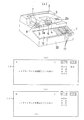
以下、この発明の実施の形態を図面に基づいて説明する。図2(a)は、この発明にかかる眼鏡加工用データ入力装置を備えるレンズ周縁加工装置(玉摺機)を示したものである。 Hereinafter, embodiments of the present invention will be described with reference to the drawings. FIG. 2 (a) shows a lens peripheral edge processing apparatus (ball grinder) provided with a spectacle processing data input apparatus according to the present invention.
この図2(a)において、1はレンズ周縁加工装置の装置本体、2は後縁部を中心に上下回動(上下揺動)可能に且つ左右動可能に装置本体1に装着されたコ字状のキャリッジ、2a,2bはキャリッジ2の左右の軸支持突部、3は軸支持突部2aに回転自在に保持されたレンズ回転軸、4は軸支持突部2bに回転自在に且つ軸線方向に移動調整可能に保持されたレンズ回転軸、5はレンズ回転軸3,4の対向端部間に保持された円形の被加工レンズ(未加工レンズ)、6は被加工レンズ5の下方に位置させて装置本体1に回転駆動可能に保持された研削砥石(研削手段)である。
In FIG. 2 (a),
尚、レンズ回転軸3,4は同軸に設けられ、図示しないパルスモータで回転駆動される様になっている。また、レンズ回転軸3の端部には円形当接部7が設けられ、この円形当接部7はキャリッジ2の自重で型受部材8上に当接している。この型受部材8は図示しないパルスモータで昇降駆動制御されるようになっている。
The
これらの研削砥石及びパルスモータを駆動制御して、レンズ回転軸3,4に保持された被加工レンズ5を回転させると共に昇降駆動制御しながら、この被加工レンズ5の周縁部を研削砥石6で眼鏡レンズ形状に研削加工する。この構成には周知の構造が採用できるので、その詳細な説明は省略する。
The
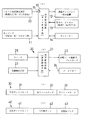
また、装置本体1には図1(a)に示した眼鏡加工用データ入力装置が設けられている。この眼鏡加工用データ入力装置は、演算制御手段(動作モード切換手段)としての演算制御回路10と、眼鏡加工用データ入力手段としてのキーボード11、表示装置(作動部)としての液晶ディスプレイ12、形状データ記憶手段としての形状データメモリ13、他のデータを記憶させるデータメモリ14、眼鏡加工用データを入力する入力部としての入力ポート15、フレーム形状測定装置20等を有する。尚、キーボード11、液晶ディスプレイ12、形状データメモリ13、データメモリ14は演算制御回路10の接続されている。しかも、フレーム形状測定装置20は入力ポート15を介して演算制御回路10に接続されている。
Further, the apparatus
また、このフレーム形状測定装置20は、回転ベース上に回転中心から半径方向に移動可能なスライダを設け、メガネフレームの眼鏡レンズ枠形状を測定するのに用いる算盤玉状の枠形状測定用フィーラーをスライダに設けると共に、リムレスフレームの玉型形状を測定するかまぼこ板状の外形測定用フィーラーを設けている。
The frame
しかも、フレーム形状測定装置20は、演算制御回路21によりパルスモータ22を駆動制御して、このパルスモータ22により回転ベース(図示せず)を回転駆動させながら、枠形状測定用フィーラーをレンズ枠のヤゲン溝に沿って移動させて、回転ベースの回転角θiにおける回転中心から枠形状測定用フィーラーまでの動径ρiを位置検出手段23で検出することにより、眼鏡レンズ枠の形状データが(ρi,θi)[ここで、i=0,1,2,3…n]として極座標形式で求められる。この形状データ(ρi,θi)は演算制御回路21により求められてデータメモリ24に記録される。また、玉型(リムレスフレームのデモレンズを含む)の形状を測定する場合には、外形形状測定用フィーラーを用いる以外は、眼鏡レンズ枠の形状データを求める場合と同様にして測定が行われ、玉型の形状データが得られる。
In addition, the frame
この様なフレーム形状測定装置20構成は、特願平5−258358号に開示したものを採用する。従って、その詳細な説明は省略する。
The structure disclosed in Japanese Patent Application No. 5-258358 is adopted as such a frame
このフレーム形状測定装置20の演算制御回路21は、図1(c),(d)に示した様なデータ形式の眼鏡加工用データ30,40をデータメモリ24内に構築する。図1(c)の眼鏡加工用データ30は、冗長データ31、メガネフレームの右眼鏡レンズ枠形状データ(右フレームデータ)32及び左眼鏡レンズ枠形状データ(左フレームデータ)33の順に形成されている。また、図1(d)の眼鏡加工用データ40は、冗長データ41、リムレスフレームの右眼鏡レンズ形状データ(右型板データ)42及び左眼鏡レンズ形状データ(左型板データ)43の順に形成されている。
The
上述した先頭の冗長データ31,41のブロックの1バイトには、眼鏡加工用データ30,40がメガネフレームのデータであるかリムレスフレーム(リムレスメガネ)の型板のデータであるかを示す情報が入っている。即ち、冗長データ31の所定バイトの内の1バイトは、メガネフレームの眼鏡レンズ枠の形状データをトレース(測定)して求めたことを示す認識コード(フラグ)として用いられる。この認識コードとしては「1」が割り当てられる。また、冗長データ41の所定バイトの内の1バイトは、リムレスフレームの眼鏡レンズの形状データをトレース(測定)して求めたことを示す認識コード(フラグ)として用いられる。この認識コードとしては「0」が割り当てられる。
In one byte of the block of the first
この認識コードは、玉型の形状測定状態を検出させるスイッチ25からの検出信号を基に構築される。このスイッチ25は、フレーム形状測定装置20に設けられており、眼鏡レンズ枠または玉型を保持するホルダがこのスイッチ25に当接すると、当接信号(検出信号)として出力し、この当接検出信号は演算制御回路21に入力する。そして、スイッチ25からの当接検出信号を受けた場合には、認識コード「0」を有する冗長データ31をデータメモリ24記憶させ、スイッチ25からの当接検出信号がない場合には認識コード「1」を有する冗長データ41をデータメモリ24に記憶させる。また、上述の形状測定装置20は、FPDも求めることができる。
This recognition code is constructed based on a detection signal from the
そして、レンズ周縁加工装置の演算制御回路10は、演算制御回路21から上述の眼鏡加工用レンズデータ30を入力ポート15を介して受けると、冗長データ31の認識コード「1」から眼鏡加工用レンズデータ30即ちレンズ枠形状データ32,33がメガネフレームの形状データであることを検知して、図2(b)に示した様に、「オート」の下に「FPD」の動作モード(入力モード)を液晶ディスプレイ12に表示させる。
When the
この「FPD」の表示がされると、メガネフレームの眼鏡レンズ枠形状データの入力モードとなり、「FPD」の右隣に例えば図2(b)に示したように「70.0」の様な幾何学中心間距離FPDの値がフレーム形状測定装置20から入力される。尚、この幾何学中心間距離FPDの値がフレーム形状測定装置20から入力されない場合には、レンズ周縁加工装置の演算制御回路10によって、FPDの値を演算することもできる。
When “FPD” is displayed, the spectacle lens frame shape data input mode of the spectacle frame is entered, and for example, “70.0” as shown in FIG. 2B is displayed on the right side of “FPD”. A value of the geometric center distance FPD is input from the frame
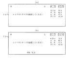
この状態では、FPDの下のPD,UP,サイズの隣にそれぞれのデータが入力可能となるので、PD,UP,サイズ等の値をキーボード11から入力する。例えば、図3(a)に示したように、PDに64.0mm,UPに+2.0mm,サイズに+0.00mm等の眼鏡加工用データ(眼鏡作成のための処方箋)をキーボード11から入力する。ここで、PDは装用者の瞳孔間距離(以下、PDと略す)、UPは上寄せ量である。
In this state, data can be input next to the PD, UP, and size under the FPD, and values such as PD, UP, and size are input from the
一方、レンズ周縁加工装置の演算制御回路10は、演算制御回路21から上述の眼鏡加工用レンズデータ40を入力ポート15を介して受けると、冗長データ41の認識コード「0」から眼鏡加工用レンズデータ40即ちレンズ形状データ42,43がリムレスフレームの型板形状データであることを検知して、図2(c)に示した様に、「オート」の下に「←B→」の動作モード(入力モード)を液晶ディスプレイ12に表示させる。
On the other hand, when the
この「←B→」の表示がされると、リムレスフレームの眼鏡レンズ形状データの入力モードとなり、「←B→」の右隣にリムレスフレームのブリッジ幅Bのデータが入力可能な状態となると共に、「←B→」の下のPD,UP,サイズの隣にそれぞれのデータが入力可能となる。 When this “← B →” is displayed, the lens lens shape data input mode of the rimless frame is entered, and the bridge width B data of the rimless frame can be input to the right of “← B →”. Each data can be input next to PD, UP, and size under “← B →”.
この状態で、「←B→」,PD,UP,サイズ等をキーボード11から入力する。例えば、図3(b)に示したように、ブリッジ幅Bに14.0mm,PDに64.0mm,UPに+2.0mm,サイズに+0.00mm等のデータをキーボード11から入力する。この入力により、演算制御回路10は、レンズ形状データ42,43とブリッジ幅「←B→」の値からリムレスフレームのFPDを求め、このFPD値を液晶ディスプレイ12の下部の「FPD」の表示の隣に例えば70.0mmと表示させる。
In this state, “← B →”, PD, UP, size, etc. are input from the
尚、動作モード(入力モード)の表示は、「←B→」の「B」以外に、「DBL」や「鼻幅」或は「ブリッジ幅」等としてもよい。 The display of the operation mode (input mode) may be “DBL”, “nose width”, “bridge width”, etc., in addition to “B” of “← B →”.
また、液晶ディスプレイ12への動作モードの表示としては単なるFPDや「←B→」に代えて図4に示した様にしてもよい。即ち、図4(a)に示したように、リムレスフレーム像30のブリッジ31の部分の上側に「←B→」の表示をさせ、リムレスフレーム像30の下側に左右レンズ32,33の幾何学中心間距離「←FPD→」の表示をさせるようにしてもよい。
The display of the operation mode on the
しかも、この表示がされると、「←B→」や「←FPD→」の部分に実際のデータが表示可能となっている。また、ブリッジ幅の実際の値が入力されると、例えば14.0mmが入力されると、「←B→」の「B」の表示が図4(b)の如く入力された値の14.0の表示になる。この状態では、ブリッジ幅Bの他にPD,UP,サイズ等のデータが入力可能となり、例えばPDに64.0mm,UPに+2.0mm,サイズに+0.00mm等のデータをキーボード11から入力する。
In addition, when this display is made, the actual data can be displayed in the portions “← B →” and “← FPD →”. When the actual value of the bridge width is input, for example, when 14.0 mm is input, the display of “B” of “← B →” is the same as the input value of 14 as shown in FIG. 0 is displayed. In this state, data such as PD, UP, and size can be input in addition to the bridge width B. For example, data such as 64.0 mm for PD, +2.0 mm for UP, and +0.00 mm for size can be input from the
そして、演算制御回路10は、ブリッジ幅やレンズ形状データからFPD値を演算して、「←FPD→」の「FPD」部分に実際のデータとして例えば「70.0mm」を表示する。この様な表示は、メガネフレームの動作モードの表示にも適用できる。この場合には、ブリッジ幅の「←B→」をしない様にする。また、PD,UP,サイズ等を「←B→」や「FPD」と同様にリムレスフレーム像30等に重ねて表示させることもできる。
Then, the
以上説明したように、この発明の実施の形態では、眼鏡レンズの加工のために入力されるレンズ枠形状データと型板形状データの種類に応じて自動的に動作モードを切換設定でき、データの入力操作が容易である。 As described above, according to the embodiment of the present invention, the operation mode can be automatically switched and set according to the types of lens frame shape data and template shape data input for the processing of the spectacle lens. Input operation is easy.
即ち、この発明の実施の形態では、リムレスフレームの形状データを入力する形状データ入力部(入力ポート15)と、前記リムレスフレームのブリッジ幅を入力すると共に、前記リムレスフレームの眼鏡加工用データを入力して、眼鏡レンズを研削加工する動作モードに切り換えるモード切換手段(演算制御回路10)を有する構成としたので、入力される眼鏡加工用の形状データからリムレスフレーム(型板)の形状データであることを検知し、リムレスフレームのブリッジ幅を入力することができる。 That is, in the embodiment of the present invention, the shape data input unit (input port 15) for inputting the shape data of the rimless frame, the bridge width of the rimless frame, and the eyeglass processing data of the rimless frame are input. Thus, since the mode switching means (arithmetic control circuit 10) for switching to the operation mode for grinding the spectacle lens is provided, the shape data of the rimless frame (template) is input from the shape data for spectacle processing. And the bridge width of the rimless frame can be input.
15…入力ポート(形状データ入力部)
10…演算制御回路(モード切換手段)
15 ... Input port (shape data input part)
10: Arithmetic control circuit (mode switching means)
Claims (2)
前記形状データ入力部を介して入力される前記形状データが眼鏡レンズ枠の形状データであるかリムレスフレームの眼鏡レンズの形状データであるかを前記認識コードから識別する制御回路と、
前記制御回路に眼鏡加工用のデータを入力する眼鏡加工用データ入力手段と、
前記眼鏡レンズの幾何学中心間距離の入力モードの表示と前記リムレスフレームのブリッジ幅の入力モードの表示を選択的にさせる表示装置とを備え、
前記制御回路は、前記形状データ入力部に入力される前記形状データが前記認識コードから前記眼鏡レンズ枠の形状データであると認識した場合、前記表示装置に前記幾何学中心間距離の入力モードの表示をさせ、且つ、前記形状データ入力部に入力される前記形状データが前記認識コードから前記リムレスフレームの形状データであると認識した場合、前記表示装置に前記ブリッジ幅の入力モードの表示をさせることを特徴とする眼鏡加工用データ入力装置。 A shape data input unit for inputting shape data to which a recognition code for identifying whether it is shape data of a spectacle lens frame or shape data of a spectacle lens of a rimless frame ;
A control circuit for identifying from the recognition code whether the shape data input through the shape data input unit is shape data of a spectacle lens frame or shape data of a spectacle lens of a rimless frame;
Eyeglass processing data input means for inputting eyeglass processing data to the control circuit;
A display device that selectively displays the input mode display of the geometric center distance of the spectacle lens and the input mode of the bridge width of the rimless frame,
When the control circuit recognizes that the shape data input to the shape data input unit is the shape data of the spectacle lens frame from the recognition code, the control circuit inputs the geometric center distance input mode. When the shape data input to the shape data input unit is recognized as the shape data of the rimless frame from the recognition code, the display device displays the bridge width input mode. A data input device for processing spectacles.
A lens peripheral edge processing apparatus comprising the spectacles processing data input device according to claim 1.
Priority Applications (1)
| Application Number | Priority Date | Filing Date | Title |
|---|---|---|---|
| JP2005256382A JP4091069B2 (en) | 2005-09-05 | 2005-09-05 | Data input device for eyeglass processing and lens peripheral processing device having the same |
Applications Claiming Priority (1)
| Application Number | Priority Date | Filing Date | Title |
|---|---|---|---|
| JP2005256382A JP4091069B2 (en) | 2005-09-05 | 2005-09-05 | Data input device for eyeglass processing and lens peripheral processing device having the same |
Related Parent Applications (1)
| Application Number | Title | Priority Date | Filing Date |
|---|---|---|---|
| JP06647396A Division JP3878240B2 (en) | 1996-03-22 | 1996-03-22 | Eyeglass processing data input device and lens periphery processing device using the same |
Publications (2)
| Publication Number | Publication Date |
|---|---|
| JP2005342892A JP2005342892A (en) | 2005-12-15 |
| JP4091069B2 true JP4091069B2 (en) | 2008-05-28 |
Family
ID=35495718
Family Applications (1)
| Application Number | Title | Priority Date | Filing Date |
|---|---|---|---|
| JP2005256382A Expired - Lifetime JP4091069B2 (en) | 2005-09-05 | 2005-09-05 | Data input device for eyeglass processing and lens peripheral processing device having the same |
Country Status (1)
| Country | Link |
|---|---|
| JP (1) | JP4091069B2 (en) |
-
2005
- 2005-09-05 JP JP2005256382A patent/JP4091069B2/en not_active Expired - Lifetime
Also Published As
| Publication number | Publication date |
|---|---|
| JP2005342892A (en) | 2005-12-15 |
Similar Documents
| Publication | Publication Date | Title |
|---|---|---|
| US6702653B2 (en) | Eyeglass lens processing apparatus | |
| JP5331464B2 (en) | Spectacle lens processing apparatus and spectacle lens processing method | |
| US7840294B2 (en) | Layout setting device for processing eyeglass lens, eyeglass lens processing apparatus, eyeglass frame measuring device and cup attaching device, each having the same | |
| US6290569B1 (en) | Lens grinding apparatus | |
| JPH0320603A (en) | Apparatus for measuring shape of lens to be machined | |
| JPH1148114A (en) | Method and device for measuring eyeglass frame, and eyeglass lens grinding device provided therewith | |
| JP2003295133A (en) | Method of determining v-groove curve, method of determining locus of v-groove, method of fabricating lens, and apparatus for fabricating lens | |
| US6641460B2 (en) | Lens grinding apparatus | |
| JP4169923B2 (en) | Lens grinding method and lens grinding apparatus | |
| JPS58177256A (en) | Lens periphery processing machine | |
| JP4091069B2 (en) | Data input device for eyeglass processing and lens peripheral processing device having the same | |
| JP3878240B2 (en) | Eyeglass processing data input device and lens periphery processing device using the same | |
| JP3953960B2 (en) | Method and apparatus for clamping workpiece lens | |
| JPH07186027A (en) | Lens grinding system | |
| JPH10328991A (en) | Lens grinding and machining device | |
| JPH0611467B2 (en) | Lens peripheral processing machine | |
| JP6236786B2 (en) | Eyeglass lens processing equipment | |
| JPH1058294A (en) | Eyeglass lens suitability determination device | |
| JP3893081B2 (en) | Eyeglass lens processing equipment | |
| JPH07186025A (en) | Lens chamfering device | |
| JP2718498B2 (en) | Raw lens judgment device for ball milling machine | |
| JP3142362B2 (en) | Lens grinding apparatus and lens grinding method | |
| JP2013178432A (en) | Method of determining processing data of spectacle lens | |
| EP3480639B1 (en) | Eyeglass lens processing devices and processing control data-creation programs | |
| JP2005238378A (en) | Processing method for eyeglass lenses |
Legal Events
| Date | Code | Title | Description |
|---|---|---|---|
| A621 | Written request for application examination |
Free format text: JAPANESE INTERMEDIATE CODE: A621 Effective date: 20050905 |
|
| A131 | Notification of reasons for refusal |
Free format text: JAPANESE INTERMEDIATE CODE: A131 Effective date: 20070710 |
|
| A521 | Written amendment |
Free format text: JAPANESE INTERMEDIATE CODE: A523 Effective date: 20070810 |
|
| TRDD | Decision of grant or rejection written | ||
| A01 | Written decision to grant a patent or to grant a registration (utility model) |
Free format text: JAPANESE INTERMEDIATE CODE: A01 Effective date: 20080226 |
|
| A61 | First payment of annual fees (during grant procedure) |
Free format text: JAPANESE INTERMEDIATE CODE: A61 Effective date: 20080227 |
|
| R150 | Certificate of patent or registration of utility model |
Free format text: JAPANESE INTERMEDIATE CODE: R150 |
|
| FPAY | Renewal fee payment (event date is renewal date of database) |
Free format text: PAYMENT UNTIL: 20110307 Year of fee payment: 3 |
|
| FPAY | Renewal fee payment (event date is renewal date of database) |
Free format text: PAYMENT UNTIL: 20110307 Year of fee payment: 3 |
|
| FPAY | Renewal fee payment (event date is renewal date of database) |
Free format text: PAYMENT UNTIL: 20120307 Year of fee payment: 4 |
|
| FPAY | Renewal fee payment (event date is renewal date of database) |
Free format text: PAYMENT UNTIL: 20120307 Year of fee payment: 4 |
|
| FPAY | Renewal fee payment (event date is renewal date of database) |
Free format text: PAYMENT UNTIL: 20130307 Year of fee payment: 5 |
|
| FPAY | Renewal fee payment (event date is renewal date of database) |
Free format text: PAYMENT UNTIL: 20130307 Year of fee payment: 5 |
|
| FPAY | Renewal fee payment (event date is renewal date of database) |
Free format text: PAYMENT UNTIL: 20140307 Year of fee payment: 6 |
|
| R250 | Receipt of annual fees |
Free format text: JAPANESE INTERMEDIATE CODE: R250 |
|
| R250 | Receipt of annual fees |
Free format text: JAPANESE INTERMEDIATE CODE: R250 |
|
| R250 | Receipt of annual fees |
Free format text: JAPANESE INTERMEDIATE CODE: R250 |
|
| EXPY | Cancellation because of completion of term |