JP4090522B2 - Portable computer outer case - Google Patents
Portable computer outer case Download PDFInfo
- Publication number
- JP4090522B2 JP4090522B2 JP10200095A JP10200095A JP4090522B2 JP 4090522 B2 JP4090522 B2 JP 4090522B2 JP 10200095 A JP10200095 A JP 10200095A JP 10200095 A JP10200095 A JP 10200095A JP 4090522 B2 JP4090522 B2 JP 4090522B2
- Authority
- JP
- Japan
- Prior art keywords
- computer
- case
- keyboard
- portable computer
- portable
- Prior art date
- Legal status (The legal status is an assumption and is not a legal conclusion. Google has not performed a legal analysis and makes no representation as to the accuracy of the status listed.)
- Expired - Fee Related
Links
Images


Classifications
-
- B—PERFORMING OPERATIONS; TRANSPORTING
- B29—WORKING OF PLASTICS; WORKING OF SUBSTANCES IN A PLASTIC STATE IN GENERAL
- B29B—PREPARATION OR PRETREATMENT OF THE MATERIAL TO BE SHAPED; MAKING GRANULES OR PREFORMS; RECOVERY OF PLASTICS OR OTHER CONSTITUENTS OF WASTE MATERIAL CONTAINING PLASTICS
- B29B17/00—Recovery of plastics or other constituents of waste material containing plastics
-
- H—ELECTRICITY
- H04—ELECTRIC COMMUNICATION TECHNIQUE
- H04M—TELEPHONIC COMMUNICATION
- H04M1/00—Substation equipment, e.g. for use by subscribers
- H04M1/02—Constructional features of telephone sets
- H04M1/18—Telephone sets specially adapted for use in ships, mines, or other places exposed to adverse environment
- H04M1/185—Improving the rigidity of the casing or resistance to shocks
-
- B—PERFORMING OPERATIONS; TRANSPORTING
- B29—WORKING OF PLASTICS; WORKING OF SUBSTANCES IN A PLASTIC STATE IN GENERAL
- B29C—SHAPING OR JOINING OF PLASTICS; SHAPING OF MATERIAL IN A PLASTIC STATE, NOT OTHERWISE PROVIDED FOR; AFTER-TREATMENT OF THE SHAPED PRODUCTS, e.g. REPAIRING
- B29C43/00—Compression moulding, i.e. applying external pressure to flow the moulding material; Apparatus therefor
- B29C43/003—Compression moulding, i.e. applying external pressure to flow the moulding material; Apparatus therefor characterised by the choice of material
-
- B—PERFORMING OPERATIONS; TRANSPORTING
- B29—WORKING OF PLASTICS; WORKING OF SUBSTANCES IN A PLASTIC STATE IN GENERAL
- B29C—SHAPING OR JOINING OF PLASTICS; SHAPING OF MATERIAL IN A PLASTIC STATE, NOT OTHERWISE PROVIDED FOR; AFTER-TREATMENT OF THE SHAPED PRODUCTS, e.g. REPAIRING
- B29C43/00—Compression moulding, i.e. applying external pressure to flow the moulding material; Apparatus therefor
- B29C43/22—Compression moulding, i.e. applying external pressure to flow the moulding material; Apparatus therefor of articles of indefinite length
-
- G—PHYSICS
- G06—COMPUTING; CALCULATING OR COUNTING
- G06F—ELECTRIC DIGITAL DATA PROCESSING
- G06F1/00—Details not covered by groups G06F3/00 - G06F13/00 and G06F21/00
- G06F1/16—Constructional details or arrangements
- G06F1/1613—Constructional details or arrangements for portable computers
- G06F1/1626—Constructional details or arrangements for portable computers with a single-body enclosure integrating a flat display, e.g. Personal Digital Assistants [PDAs]
-
- G—PHYSICS
- G06—COMPUTING; CALCULATING OR COUNTING
- G06F—ELECTRIC DIGITAL DATA PROCESSING
- G06F1/00—Details not covered by groups G06F3/00 - G06F13/00 and G06F21/00
- G06F1/16—Constructional details or arrangements
- G06F1/1613—Constructional details or arrangements for portable computers
- G06F1/1633—Constructional details or arrangements of portable computers not specific to the type of enclosures covered by groups G06F1/1615 - G06F1/1626
- G06F1/1656—Details related to functional adaptations of the enclosure, e.g. to provide protection against EMI, shock, water, or to host detachable peripherals like a mouse or removable expansions units like PCMCIA cards, or to provide access to internal components for maintenance or to removable storage supports like CDs or DVDs, or to mechanically mount accessories
-
- H—ELECTRICITY
- H01—ELECTRIC ELEMENTS
- H01H—ELECTRIC SWITCHES; RELAYS; SELECTORS; EMERGENCY PROTECTIVE DEVICES
- H01H9/00—Details of switching devices, not covered by groups H01H1/00 - H01H7/00
- H01H9/02—Bases, casings, or covers
- H01H9/04—Dustproof, splashproof, drip-proof, waterproof, or flameproof casings
-
- H—ELECTRICITY
- H04—ELECTRIC COMMUNICATION TECHNIQUE
- H04M—TELEPHONIC COMMUNICATION
- H04M1/00—Substation equipment, e.g. for use by subscribers
- H04M1/02—Constructional features of telephone sets
- H04M1/0202—Portable telephone sets, e.g. cordless phones, mobile phones or bar type handsets
-
- H—ELECTRICITY
- H01—ELECTRIC ELEMENTS
- H01H—ELECTRIC SWITCHES; RELAYS; SELECTORS; EMERGENCY PROTECTIVE DEVICES
- H01H11/00—Apparatus or processes specially adapted for the manufacture of electric switches
-
- H—ELECTRICITY
- H01—ELECTRIC ELEMENTS
- H01H—ELECTRIC SWITCHES; RELAYS; SELECTORS; EMERGENCY PROTECTIVE DEVICES
- H01H9/00—Details of switching devices, not covered by groups H01H1/00 - H01H7/00
-
- Y—GENERAL TAGGING OF NEW TECHNOLOGICAL DEVELOPMENTS; GENERAL TAGGING OF CROSS-SECTIONAL TECHNOLOGIES SPANNING OVER SEVERAL SECTIONS OF THE IPC; TECHNICAL SUBJECTS COVERED BY FORMER USPC CROSS-REFERENCE ART COLLECTIONS [XRACs] AND DIGESTS
- Y02—TECHNOLOGIES OR APPLICATIONS FOR MITIGATION OR ADAPTATION AGAINST CLIMATE CHANGE
- Y02W—CLIMATE CHANGE MITIGATION TECHNOLOGIES RELATED TO WASTEWATER TREATMENT OR WASTE MANAGEMENT
- Y02W30/00—Technologies for solid waste management
- Y02W30/50—Reuse, recycling or recovery technologies
- Y02W30/62—Plastics recycling; Rubber recycling
Description
【0001】
【産業上の利用分野】
本発明は、衝撃吸収および防水機能を有する携帯用電子機器に関し、より詳しくは、プラスチックにゴム製品を射出した形態の二重構造でケースを形成してノートブックコンピュータ、ペンコンピュータのような携帯用情報処理機器や携帯用電話機などに適切に適用することにより、衝撃および振動の吸収性を向上させるとともに防水可能にし、また、ケース表面の触感を向上できる衝撃吸収および防水機能を有する携帯用電子機器に関するものである。
【0002】
【従来の技術】
最近まで、ノートブックコンピュータ、ペンコンピュータなどの携帯用電子機器の外部ケースとしてはポリカーボネート(PC:Poly Carbonate)およびアクリロブチレンスチレン樹脂の組成物やアクリロブチレンスチレン(ABS:Acrylo Butylene Styrene )樹脂のようなプラスチック樹脂を射出して製造している。
【0003】
前述の携帯用電子機器の外部ケースは、材質の特性上耐衝撃吸収性が劣り、携帯用電子機器に落下事故が発生した場合、外部ケースの破損のみならず内装部品の損傷も招く。
【0004】
【発明が解決しようとする課題】
したがって、本発明は、硬い材質のプラスチック樹脂にゴム成分の合成樹脂を射出した外部ケースを提供することにより、携帯用電子機器の振動および耐衝撃吸収力を向上させることを目的としている。
【0005】
本発明の他の目的は、外部ケースに使用されたゴム成分の合成樹脂から感じられるソフトな触感を使用者に提供することにより製品の価値をもっと高級にすることにある。
【0006】
本発明のさらに他の目的は、携帯用電話機、または、携帯用コンピュータなどのキー入力ボタンをゴム成分の合成樹脂を用いて形成することにより、キー入力ボタン製造に必要な費用を節減できるようにすることにある。
【0007】
一方、コンピュータの外部ケースがゴム製品である場合には、弾性を有して硬くないゴムの特性上、ヒンジでドアをケース上に装着し難い。また、ペンコンピュータにおいては、キーボードがあまり使用されないので、キーボードポート用キャップが紛失されることを防止する対策が必要になる。
【0008】
したがって、本発明は、ドア側リブおよびストッパにより連結部材をドア、または、キャップに固く固定し、前記連結部材をコンピュータ本体に連結し、ドアまたはキャップが常時コンピュータ本体から離脱されないようにし、ドアまたはキャップの紛失を防止できるようにすることをさらに目的としている。
【0009】
【課題を解決するための手段】
上記目的を達成するための本発明の構成は、
携帯用電子機器を構成している内部部品と、
硬い物性を利用して内部空間を形成することにより前記内部部品を保護できるケースの役割をするプラスチック部材と、
前記プラスチック部材に吸着され外部表面を形成し、外部からの衝撃および振動を吸収し、防水機能を有するとともにソフトな質感を提供するゴム材とからなる。
【0010】
上記目的を達成するための本発明の他の構成は、
一次鋳型にプラスチック樹脂を射出してプラスチック部材を形成し、
前記プラスチック部材を二次鋳型に挿入した後、
前記プラスチック部材上にゴム成分の合成樹脂を適切な厚さで射出しプラスチック部材に吸着されたゴム部材が形成されるようにする製造工程でなる。
【0011】
上記目的を達成するための本発明のさらに他の構成は、
外部の衝撃および異物の流入からドア内部を保護するためのゴム材料でなっている補助ドアと、
前記補助ドアの内面に形成され内部溝を有するリブと、
一側溝に前記リブを挿入し、他側の掛かり溝がコンピュータの本体に掛かるようにし、補助ドアとコンピュータが連結されるようにする連結部材と、
前記連結部材が挿入されたリブの内部溝に挿入され、敷居によりリブの中端部が膨張され連結部材がリブから外れないようにするストッパとからなる。
【0012】
【実施例】
以下、本発明の好適実施例を、添付図面に基づいて説明する。
【0013】
本発明の実施例では、携帯用電子機器として携帯用コンピュータ(図1〜図12)および携帯用電話機(図13および図14)に対してだけ説明しているが、本発明の技術的な範囲はこれに限定されるものではなく、他の携帯用電子機器にも適当な変形を通じて同一の技術を適用することができる。
【0014】
まず、携帯用コンピュータについて説明する。
図1に示すように、本発明の実施例による衝撃吸収および防水機能を有するコンピュータの上部ケースは、ケース内部表面をなすプラスチック部材12と、前記プラスチック部材12に吸着されるゴム部材11と、上部ケースと下部ケースの間に差込み組立てられるメインガスケット13とからなる。
【0015】
前記プラスチック部材12は、ポリカーボネートおよびアクリロブチレンスチレン樹脂の組成物やアクリロブチレンスチレン樹脂でなり、前記ゴム部材11はゴム成分の合成樹脂の1種であるデュポン(Du Pont )社のHYTREL樹脂でなる。
【0016】
前記HYTREL樹脂は、ブロック共重合体(block copolymers)で、ハード成分のポリブチレンテレフタレート(PBT:Poly Butylene Terephthalate )と、ソフト成分の長鎖ポリエーテルグリコール(Polyether Glycols )とからなり、前記ハード成分とソフト成分の含有比率によりその属性が決定される。
【0017】
前記HYTREL樹脂は、機械的強度および耐久性が要求される部品に主に適用されている。
【0018】
図1で、プラスチック部材12の後端部には出力ポートドアが挿入される二重敷居が形成されており、これは、防水効果を遂行するためのもので、メインガスケット13に接着されているガスケット支持台131はアルミニウム板でなり組立てられた状態で上部ケースと下部ケースを固定するもので、コンピュータケースに衝撃が加わって上部ケースと下部ケースが離脱されることを防止する。
【0019】
図1では、上部ケースの断面のみを図示しており、下部ケースの断面は図1に基づいて類推でき、図2に概略的な外観が図示されている。
【0020】
前記携帯用コンピュータの上部ケース、または下部ケースを製造する方法について説明する。
【0021】
コンピュータの上部、または下部ケースのための鋳型に前記ポリカーボネートおよびアクリロブチレンスチレン樹脂の組成物やアクリロブチレンスチレン樹脂を射出してプラスチック部材12を形成する。
【0022】
上記形成された上部、または下部ケース用プラスチック部材12は、上部、または下部ケースのための二次鋳型に挿入され、次に、上部または下部ケース用プラスチック部材12上にHYTREL樹脂を1.2〜2.0mmの厚さで射出して携帯用コンピュータの上部、または下部ケースが得られる。
【0023】
図2および図3は、上記のように製造された携帯用コンピュータの上部および下部ケース21、22がメインガスケット13とともに組立てられた状態を示す斜視図である。
【0024】
図2は、携帯用コンピュータの上部を図示したもので、上部ケース21、メインガスケット13、下部ケース22とが組立てられている。
【0025】
図3は、携帯用コンピュータの下部を図示したもので、下部ケース22の左右には半円形柱が形成され、コンピュータが底に安定的に支持される。
【0026】
図4および図5は携帯用コンピュータの上部ケース21および下部ケース22に内部部品が組立てられることを示す。
【0027】
図4に基づいて、携帯用コンピュータの上部ケース21に内部部品が組立てられる過程を説明する。
【0028】
まず、上部ケース21の表示装置のための溝の内部枠にトレーガスケット310が装着される。前記トレーガスケット310はトレーガスケット310上に配置される物体と上部ケース21との間で緩衝作用および防水作用を遂行する。
【0029】
前記トレーガスケット310上には、底面に左右にバッジ312、314が接着された下部支持台316が装着され、前記下部支持台316は、液晶表示器324を支持する。下部支持台316の左側上部にはテープ320が接着され、左側面には米国連邦通信委員会(Federal Communications Commission, FCC)の規格に従う通信ケーブル318が装着される。
【0030】
下部支持台316上には液晶表示器ガスケット322が装着され、液晶表示器ガスケット322は液晶表示器324と下部支持台316との間の緩衝作用を遂行する。前記液晶表示器ガスケット322上にはコンピュータの表示装置で使用される液晶表示器324が装着され、前記液晶表示器324の左側には液晶表示器ケーブル326が連結されている。
【0031】
液晶表示器324上にはデジタイザ330と液晶表示器324との間で緩衝作用を遂行するデジタイザガスケット328が装着され、デジタイザガスケット328上にはコンピュータのペン入力信号を処理するデジタイザ330が装着される。
【0032】
デジタイザ330上には上部覆い332が装着され、上部覆い332の下部前後側にはデジタイザ330と上部覆い332との間で緩衝作用を遂行する6つの覆い側ガスケット334が装着される。上部覆い332は液晶表示器324の撓みを防止するためのもので、強度を増強させるためにマグネシウム合金が使用されている。
【0033】
一方、図4には図示されていないが、上部覆い332上にはコンピュータシステムのメインボードが装着され、前記メインボードに関する構成は、図6に図示されている。
【0034】
次に、図5に基づいて携帯用コンピュータの下部ケース22に内部部品が組立てられる過程を説明する。
【0035】
まず、バッテリ350が下部ケース22の底面後端部に装着される。バッテリ350は下部ケース22のバッテリ350のための空間に差込み組立てられる。
【0036】
バッテリ350の後端部には組立ねじ354によりバッテリピン352およびピン側ガスケット356がねじ結合される。ピン側ガスケット356の後端にはブラケット358が装着され、ブラケット358の後端には支持台360が結合されている赤外線基盤362および基盤側ガスケット364が装着される。前記赤外線基盤362は外部装置と通信するためのもので、基盤側ガスケット364は赤外線基盤362とレンズ370との間で緩衝作用を遂行する。
【0037】
前記赤外線基盤364の後端にはレンズ370およびレンズガスケット368がボルト366により結合され、前記レンズガスケット368はレンズ370がボルト366により損傷されることを防止する。
【0038】
図6は、コンピュータのメインボードの構成ブロック図であり、図6に基づいてメインボードの動作を説明する。
【0039】
中央処理ユニット410はローカルバスを通じてRAM412およびシステムコントローラ414と連結され、前記中央処理ユニット410としては486DX、486DX2などのマイクロプロセッサチップが使用される。
【0040】
RAM412はコンピュータシステムのメインメモリとして使用され、4MB、8MB、16MBの容量を有し、JEDECメモリなどがRAM412に結合されることによりコンピュータシステムのメインメモリの容量が追加に拡張できる。
【0041】
システムコントローラ414は、ローカルバスを通じて中央処理ユニット410と連結され、同時に、システムバスと連結され、中央処理ユニット410とシステムバスとの間でインタフェースの役割を遂行し、DRAMコントローラおよびパワーマネージャとしての役割も遂行する。
【0042】
ローカルバスを通じてキーボードコントローラ418、ROM420、バッテリ422と連結され、同時に、システムバスに連結されている内部ロジックコントローラ416は、コンピュータシステム内部の並列ポート、インタラプト、および直接メモリアクセス(Direct Memory Access, DMA )を制御する。前記内部ロジックコントローラ416には、コンピュータシステムに標準時間を提供する実時間時計(Real Time Clock, RTC)機能と、タイマ機能が含まれている。
【0043】
キーボードコントローラ418は、キーボードで押したキーに対応するスキャンコードを生じさせ、前記スキャンコードがローカルバス、バッファ422、システムバス、システムコントローラ414を経由してインタラプト方式により中央処理ユニット410に伝達されるようにする。
【0044】
ROM420には、BIOS(Basic Input Output System, BIOS )プログラムおよび各種インタラプトサービスルーチンと、初期ブーティング(booting )時コンピュータシステムのチェッキングルーチン(Power On Self Test, POST)などが貯蔵されている。
【0045】
バッファ422は、内部ロジックコントローラ416、キーボードコントローラ418、ROM420を連結するローカルバスとシステムバスとの間でインタフェースの役割を遂行する。
【0046】
システムバスに連結されており、国際協約により規格が定まっているパーソナルコンピュータメモリカード(Personal Computer Memory Card International Association, PCMCIA )を制御するPCMCIAコントローラ434には、メモリカードのための1以上のソケット436が連結されており、前記メモリカードはコンピュータシステムに電源が供給されている状態でも外部でソケット436が装着できるように設計されている。
【0047】
システムバスに連結されているビデオコントローラ438には表示機器442およびビデオRAM440が連結されている。前記ビデオコントローラ438は、中央処理ユニット410で生じてシステムバスを通って入力される表示機器442の両面を構成するための表示関連データから色信号、同期信号、クロック信号、色レベル信号を生じて表示機器442に伝え、ビデオRAM440には、中央処理ユニット410から伝えられた表示関連データが一時貯蔵される。
【0048】
バッファ424は、ハードディスクドライブ(Hard Disk Drive 以下、HDDという)426、フラッシュROM428、外部入出力コントローラ430、プログラムロジック装置432が連結されているローカルバスとシステムバスとを連結し、前記ローカルバスとシステムバスとの間でインタフェースの役割を遂行する。
【0049】
コンピュータシステムの各種データおよびプログラムを半永久的に記憶するための補助メモリ装置であるHDD426にはハードディスクコントローラが内挿されて使用される。
【0050】
フラッシュROM428は、コンピュータシステムのメインメモリ412の負担を軽減させるためのもので、前記フラッシュROM428にはDOS(Disk Operating System )などのオペレーティングシステム(Operating System, OS)とユーティリティ(Utility )プログラムなどが貯蔵されている。
【0051】
外部入出力コントローラ430にはアドレッシング方式によりHDD426をインタフェースするロジックが含まれており、前記外部入出力コントローラ430はフロッピィディスクドライブ(Floppy Disk Drive, FDD)を制御し、または、プリンタポートなどのような並列ポートと通信ポートのような直列ポートを制御する役割を遂行する。
【0052】
プログラムロジック430には1種のプログラム可能な論理配列装置(Programmable Logic Array, PLA )として、システムバスに連結されているバッファ422、424のバス関連制御ロジックが含まれている。
【0053】
次の表1は、携帯用ペンコンピュータの衝撃および振動テストに要求される規格である。
【0054】
【表1】

【0055】
振動テストとは、最大共鳴周波数で15分以上の振動を加えることで、携帯用ペンコンピュータが作動中には0.5G’Sの振動を加え、携帯用ペンコンピュータが作動していないときは1.0G’Sの振動を加える。
【0056】
本発明の実施例による携帯用ペンコンピュータは、前記した衝撃および振動テストで優秀な特性を現わしていることを実験から確認した。
【0057】
前記したように、携帯用コンピュータの外部ケースがゴム製品である場合は、ゴムの硬くない特性のために、ヒンジで出力ポートドアをケース上に装着し難い。また、携帯用ペンコンピュータの場合は、キーボードがあまりよく使用されないので、キーボードポート用キャップがよく紛失されることを防止するための対策が要求される。
【0058】
上記した問題点を解決するための本発明の実施例による衝撃吸収および防水機能を有する携帯用コンピュータで使用される出力ポートドアおよびキーボードポート用キャップの開閉装置に対して説明する。
【0059】
図7〜図12に示すごとく、本発明の実施例による開閉装置は、出力ポートドア3およびキーボードポート用キャップ4の内部に出力ポートドア側リブ31とキーボードキャップ側リブ41とがそれぞれ形成され、前記出力ポートドア側リブ31とキーボードキャップ側リブ41には連結部材2、5の一側溝がそれぞれ挿入され、前記連結部材2、5の他側掛かり溝はコンピュータ本体1の内部に装着され、前記連結部材2、5の一側溝が外周面に沿い挿入された前記出力ポートドア側リブ31とキーボードキャップ側リブ41の内部溝にはストッパ6が挿入される構造でなる。
【0060】
本発明の実施例で、出力ポートドア3とキーボードポート用キャップ4および出力ポートドア側リブ31とキーボードキャップ側リブ41はゴム製品でなり、連結部材2、5はポリエステル樹脂でなり、ストッパ6はプラスチック材料でなるが、本発明の技術的な範囲はこれに限定されない。
【0061】
前記構成による、本発明の実施例に係る出力ポートドアおよびキーボードポート用キャップの作用について説明する。
【0062】
まず、図8に示すように、出力ポートドア3およびキーボードポート用キャップ4に形成された出力ポートドア側リブ31とキーボードキャップ側リブ41に連結部材2、5の一側溝を差し込む。前記連結部材2、5はポリエステル樹脂の薄いフィルムで折りやすい。
【0063】
次に、出力ポートドア側リブ31およびキーボードキャップ側リブ41の内部溝にはストッパ6が挿入され、前記ストッパ6には図2のように敷居61が形成されている。前記ストッパ6の敷居61により出力ポートドア側リブ31とキーボードキャップ側リブ41の中端部は膨張され、連結部材2、5が各リブ31、41の中端部に掛かって出力ポートドア3およびキーボードポート用キャップ4に固く固定される。
【0064】
図9には、連結部材2およびストッパ6が出力ポートドア3および出力ポートドア側リブ31に固定され、前記出力ポートドア3がコンピュータ本体1に装着されている状態が図示されている。
【0065】
前述したように、出力ポートドア3およびキーボードポート用キャップ4に連結部材2、5が装着されると、連結部材2、5の他側に形成された掛かり溝がコンピュータ本体1の内部敷居に掛かるようにして出力ポートドア3およびキーボードポート用キャップ4がコンピュータ本体1に組立てられる。このとき、出力ポートドア3はコンピュータ本体1と結合され、出力ポートドア3およびコンピュータ本体1の結合部位の縁に防水機能のために二重敷居が形成されている。
【0066】
使用者により前記出力ポートドア3、またはキーボードポート用キャップ4は開閉され、出力ポートドア3またはキーボードポート用キャップ4が開いている状態で、連結部材2、5により前記出力ポートドア3またはキーボードポート用キャップ4がコンピュータ本体1に連結されているので、コンピュータから離脱されない。
【0067】
図10は、本発明の実施例による衝撃吸収および防水機能を有するコンピュータキーボードキャップ用連結部材の斜視図で、図11は、本発明の実施例による衝撃吸収および防水機能を有するコンピュータキーボードキャップ用連結部材の装着方法を示す図面で、図12は、本発明の実施例による衝撃吸収および防水機能を有するコンピュータのキーボードキャップ用連結部材の装着状態を示す図面で、キーボードポート用キャップ4に適用され連結部材21がキーボードポート用キャップ4の開閉動作に連動してコンピュータ本体1の内部で移動できることを示している。
【0068】
図10に示すごとく、連結部材21には、コンピュータ本体1側の掛かり溝の代わりに弾性力を有する突起面22が形成されている。前記突起面22はポリエステル樹脂の特性上、水平に延びる弾性力を有して、組立時に前記突起面22を折ってコンピュータ本体1の隙間に挿入すると、前記突起面22がコンピュータ本体1内部で延びて連結部材21に固く固定される。
【0069】
図11は、連結部材21がコンピュータ本体1に装着されることを図示した断面図で、装着される過程をより容易に理解させるためのものである。
【0070】
図12は、連結部材21がコンピュータ本体1に装着された状態を図示し、前記連結部材21はキーボードポート用キャップ4がコンピュータ本体1のキーボードポート用キャップ4のための溝で前後で動くとき、これに連動して移動できるようになり、ドアが閉じている状態で連結部材21のための空間が小さいキーボードポート用キャップ4などに容易に適用できる。
【0071】
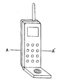
図13および図14は、本発明の他の実施例として提示されたもので、本発明の原理である二重構造の外部ケースが携帯用電話機に適用されたことを図示したものである。
【0072】
図13は、本発明の原理が適用された携帯用電話機の斜視図で、図14は図13のA−A′断面図である。
【0073】
図14に基づいて説明すれば、プラスチック部材54とその上にゴム部材52が吸着された上部ケースが具備され、下部ケースもプラスチック部材53上にゴム部材51が吸着されて具備される。
【0074】
前記上部ケースのゴム部材52の表面には番号板が印刷されゴム部材52の内部には突起が形成されており、前記突起は携帯用電話機基盤55に形成された数字番号板のためのスイッチ56の方に向かっている。したがって、使用者がゴム部材52の番号板を押すとゴム部材52の突起がスイッチ56を押すこととなり、携帯用電話機が動作される。
【0075】
上記した構成によると、携帯用電話機の外部ケースに別途のスイッチのための押し装置が必要とはならないので、押し装置を装着するための費用が節減できる。また、上記技術的原理は携帯用コンピュータなどのキー入力手段に応用できる。
【0076】
【発明の効果】
以上、本発明の実施例では、プラスチック部材にゴム部材を吸着させ携帯用機器のハウジングを製作することにより耐衝撃吸収力および振動に耐える力を向上させ、ゴム部材の特性により携帯用機器の表面触感を向上させ、スイッチボタンをゴム部材で形成してスイッチボタン製作のための別途の費用を節減できるようにする衝撃吸収および防水機能を有する携帯用電子機器を提供できる。
【0077】
また、連結部材、リブ、およびストッパによりゴム製品でなっている補助ドアをコンピュータ本体と簡単に連結することによりヒンジ装置を使用できない部分に容易に適用でき、補助ドアがコンピュータ本体から離脱されないようにして補助ドアの紛失を防止できるドア開閉装置を提供できる。
【図面の簡単な説明】
【図1】本発明の実施例による衝撃吸収および防水機能を有するコンピュータの上部ケースの断面図である。
【図2】本発明の実施例による衝撃吸収および防水機能を有するコンピュータの上面斜視図である。
【図3】本発明の実施例による衝撃吸収および防水機能を有するコンピュータの下面斜視図である。
【図4】本発明の実施例による衝撃吸収および防水機能を有するコンピュータの上部ケースの組立斜視図である。
【図5】本発明の実施例による衝撃吸収および防水機能を有するコンピュータの下部ケースの組立斜視図である。
【図6】本発明の実施例による衝撃吸収および防水機能を有するコンピュータのシステムポートを図示したブロック構成図である。
【図7】本発明の実施例による衝撃吸収および防水機能を有する携帯用コンピュータにおいて、出力ポートドアおよびキーボードキャップが開いている状態を図示した斜視図である。
【図8】本発明の実施例による衝撃吸収および防水機能を有するコンピュータの出力ポートドアの細部斜視図である。
【図9】本発明の実施例による衝撃吸収および防水機能を有するコンピュータにおいて、出力ポートドアが装着されている状態を示す断面図である。
【図10】本発明の実施例による衝撃吸収および防水機能を有するコンピュータのキーボードキャップ用連結部材の斜視図である。
【図11】本発明の実施例による衝撃吸収および防水機能を有するコンピュータのキーボードキャップ用連結部材の装着方法を示す図である。
【図12】本発明の実施例による衝撃吸収および防水機能を有するコンピュータのキーボードキャップ用連結部材の装着状態を示す図である。
【図13】本発明の他の実施例による衝撃吸収および防水機能を有する携帯用電話機の斜視図である。
【図14】本発明の他の実施例による衝撃吸収および防水機能を有する携帯用電話機の断面図である。
【符号の説明】
11 ゴム部材
12 プラスチック部材
13 メインガスケット
131 ガスケット支持台[0001]
[Industrial application fields]
The present invention relates to a portable electronic device having shock absorption and waterproof functions, and more particularly, a portable electronic device such as a notebook computer or a pen computer by forming a case with a double structure in which a rubber product is injected into plastic. Appropriately applied to information processing equipment, portable telephones, etc. to improve shock and vibration absorbability and make it waterproof, and portable electronic equipment with shock absorption and waterproof functions that can improve the tactile feel of the case surface It is about.
[0002]
[Prior art]
Until recently, the outer case of portable electronic devices such as notebook computers and pen computers has a composition of polycarbonate (PC: Poly Carbonate) and acrylobutylene styrene resin or ABS (Acrylo Butylene Styrene) resin. It is manufactured by injecting such plastic resin.
[0003]
The outer case of the above-mentioned portable electronic device is inferior in shock resistance due to the characteristics of the material, and when a drop accident occurs in the portable electronic device, not only the outer case is damaged but also the interior parts are damaged.
[0004]
[Problems to be solved by the invention]
Accordingly, an object of the present invention is to improve the vibration and impact resistance absorbing power of a portable electronic device by providing an outer case in which a synthetic resin of a rubber component is injected into a hard plastic resin.
[0005]
Another object of the present invention is to provide a user with a soft touch felt from the synthetic resin of the rubber component used in the outer case, thereby increasing the value of the product.
[0006]
Still another object of the present invention is to form a key input button of a portable telephone or a portable computer using a synthetic resin of a rubber component so that the cost required for manufacturing the key input button can be reduced. There is to do.
[0007]
On the other hand, when the external case of the computer is a rubber product, it is difficult to mount the door on the case with a hinge due to the property of rubber that is elastic and not hard. In a pen computer, since the keyboard is not used much, measures to prevent the keyboard port cap from being lost are necessary.
[0008]
Therefore, the present invention secures the connecting member to the door or the cap by the door side rib and the stopper, connects the connecting member to the computer main body, prevents the door or the cap from being always detached from the computer main body, A further object is to prevent loss of the cap.
[0009]
[Means for Solving the Problems]
The configuration of the present invention for achieving the above object is as follows.
Internal components constituting the portable electronic device;
A plastic member serving as a case capable of protecting the internal parts by forming an internal space using hard physical properties;
It is made of a rubber material that is adsorbed by the plastic member to form an external surface, absorbs shock and vibration from the outside, has a waterproof function and provides a soft texture.
[0010]
Other configurations of the present invention for achieving the above object are as follows:
Injecting plastic resin into the primary mold to form plastic parts,
After inserting the plastic member into the secondary mold,
This is a manufacturing process in which a synthetic resin of a rubber component is injected onto the plastic member with an appropriate thickness so that a rubber member adsorbed on the plastic member is formed.
[0011]
Still another configuration of the present invention for achieving the above object is as follows.
An auxiliary door made of a rubber material to protect the interior of the door from external impact and inflow of foreign matter,
A rib formed on the inner surface of the auxiliary door and having an internal groove;
A connecting member that inserts the rib into one side groove, causes the other side hanging groove to hang on the computer body, and connects the auxiliary door and the computer;
The stopper is inserted into the inner groove of the rib into which the connecting member is inserted, and the middle end of the rib is expanded by the sill so that the connecting member does not come off the rib.
[0012]
【Example】
Hereinafter, preferred embodiments of the present invention will be described with reference to the accompanying drawings.
[0013]
In the embodiments of the present invention, only portable computers (FIGS. 1 to 12) and portable telephones (FIGS. 13 and 14) are described as portable electronic devices, but the technical scope of the present invention. The present invention is not limited to this, and the same technology can be applied to other portable electronic devices through appropriate modifications.
[0014]
First, a portable computer will be described.
As shown in FIG. 1, an upper case of a computer having a shock absorbing and waterproof function according to an embodiment of the present invention includes a
[0015]
The
[0016]
The HYTREL resin is a block copolymer comprising a hard component polybutylene terephthalate (PBT) and a soft component long-chain polyether glycol (Polyether Glycols). The attribute is determined by the content ratio of the soft component.
[0017]
The HYTREL resin is mainly applied to parts that require mechanical strength and durability.
[0018]
In FIG. 1, a double sill into which an output port door is inserted is formed at the rear end of the
[0019]
In FIG. 1, only the cross section of the upper case is shown, and the cross section of the lower case can be inferred based on FIG. 1, and the schematic appearance is shown in FIG.
[0020]
A method for manufacturing the upper case or the lower case of the portable computer will be described.
[0021]
The
[0022]
The formed upper or lower
[0023]
2 and 3 are perspective views showing a state in which the upper and
[0024]
FIG. 2 illustrates the upper part of the portable computer, in which an
[0025]
FIG. 3 illustrates the lower part of the portable computer. Semicircular columns are formed on the left and right sides of the
[0026]
4 and 5 show that the internal parts are assembled in the
[0027]
Based on FIG. 4, a process of assembling internal components in the
[0028]
First, the
[0029]
A
[0030]
A liquid
[0031]
A
[0032]
An
[0033]
On the other hand, although not shown in FIG. 4, a main board of the computer system is mounted on the
[0034]
Next, a process of assembling internal components in the
[0035]
First, the
[0036]
A
[0037]
A
[0038]
FIG. 6 is a block diagram showing the configuration of the main board of the computer. The operation of the main board will be described with reference to FIG.
[0039]
The
[0040]
The
[0041]
The
[0042]
The
[0043]
The
[0044]
The
[0045]
The
[0046]
The
[0047]
A
[0048]
The
[0049]
A hard disk controller is inserted and used in
[0050]
The
[0051]
The external input / output controller 430 includes logic for interfacing with the
[0052]
The program logic 430 includes bus-related control logic of
[0053]
Table 1 below shows the standards required for impact and vibration testing of portable pen computers.
[0054]
[Table 1]
[0055]
The vibration test applies vibration of 15 minutes or more at the maximum resonance frequency. When the portable pen computer is in operation, 0.5G'S vibration is applied, and when the portable pen computer is not in operation, 1 is applied. Apply vibration of 0G'S.
[0056]
It was confirmed from experiments that the portable pen computer according to the embodiment of the present invention exhibited excellent characteristics in the above-described shock and vibration test.
[0057]
As described above, when the external case of the portable computer is a rubber product, it is difficult to attach the output port door to the case with a hinge due to the non-hard property of rubber. In the case of a portable pen computer, since the keyboard is not used very often, a countermeasure for preventing the keyboard port cap from being frequently lost is required.
[0058]
An opening and closing device for an output port door and a keyboard port cap used in a portable computer having a shock absorbing and waterproof function according to an embodiment of the present invention for solving the above-described problems will be described.
[0059]
As shown in FIGS. 7 to 12, the opening / closing device according to the embodiment of the present invention has an output port
[0060]
In the embodiment of the present invention, the
[0061]
The operation of the output port door and the keyboard port cap according to the embodiment of the present invention having the above-described configuration will be described.
[0062]
First, as shown in FIG. 8, one side grooves of the connecting
[0063]
Next, a stopper 6 is inserted into the internal grooves of the output port
[0064]
FIG. 9 shows a state in which the connecting
[0065]
As described above, when the connecting
[0066]
The
[0067]
FIG. 10 is a perspective view of a connecting member for a computer keyboard cap having shock absorption and waterproof functions according to an embodiment of the present invention, and FIG. 11 is a connection for a computer keyboard cap having shock absorbing and waterproof functions according to an embodiment of the present invention. FIG. 12 is a diagram illustrating a mounting method of a member, and FIG. 12 is a diagram illustrating a mounting state of a keyboard cap connecting member of a computer having a shock absorbing and waterproof function according to an embodiment of the present invention. This shows that the
[0068]
As shown in FIG. 10, the connecting
[0069]
FIG. 11 is a cross-sectional view illustrating that the connecting
[0070]
FIG. 12 illustrates a state in which the connecting
[0071]
FIG. 13 and FIG. 14 are presented as other embodiments of the present invention, and illustrate that a dual structure outer case which is the principle of the present invention is applied to a portable telephone.
[0072]
13 is a perspective view of a portable telephone to which the principle of the present invention is applied, and FIG. 14 is a cross-sectional view taken along line AA ′ of FIG.
[0073]
Referring to FIG. 14, a
[0074]
A number plate is printed on the surface of the
[0075]
According to the configuration described above, since a separate pressing device for the switch is not required in the outer case of the portable telephone, the cost for mounting the pressing device can be reduced. The above technical principle can be applied to key input means such as a portable computer.
[0076]
【The invention's effect】
As described above, in the embodiment of the present invention, the rubber member is adsorbed on the plastic member and the housing of the portable device is manufactured, thereby improving the shock resistance absorption force and the resistance to vibration. It is possible to provide a portable electronic device having an impact absorption and waterproof function that improves the tactile sensation and allows the switch button to be formed of a rubber member, thereby reducing the additional cost for manufacturing the switch button.
[0077]
In addition, the auxiliary door made of rubber can be easily connected to the computer body by connecting members, ribs, and stoppers, so that it can be easily applied to parts where the hinge device cannot be used, so that the auxiliary door is not detached from the computer body. Thus, it is possible to provide a door opening and closing device that can prevent the loss of the auxiliary door.
[Brief description of the drawings]
FIG. 1 is a cross-sectional view of an upper case of a computer having shock absorption and waterproof functions according to an embodiment of the present invention.
FIG. 2 is a top perspective view of a computer having shock absorption and waterproof functions according to an embodiment of the present invention.
FIG. 3 is a bottom perspective view of a computer having shock absorption and waterproof functions according to an embodiment of the present invention.
FIG. 4 is an assembled perspective view of an upper case of a computer having shock absorption and waterproof functions according to an embodiment of the present invention.
FIG. 5 is an assembled perspective view of a lower case of a computer having a shock absorbing and waterproof function according to an embodiment of the present invention.
FIG. 6 is a block diagram illustrating a system port of a computer having shock absorption and waterproof functions according to an embodiment of the present invention.
FIG. 7 is a perspective view illustrating a state in which an output port door and a keyboard cap are opened in a portable computer having shock absorption and waterproof functions according to an embodiment of the present invention.
FIG. 8 is a detailed perspective view of an output port door of a computer having shock absorption and waterproof functions according to an embodiment of the present invention.
FIG. 9 is a cross-sectional view showing a state in which an output port door is mounted in a computer having shock absorption and waterproof functions according to an embodiment of the present invention.
FIG. 10 is a perspective view of a connecting member for a keyboard cap of a computer having a shock absorbing and waterproof function according to an embodiment of the present invention.
FIG. 11 is a diagram illustrating a method of attaching a keyboard cap connecting member of a computer having shock absorption and waterproof functions according to an embodiment of the present invention.
FIG. 12 is a diagram showing a mounting state of a keyboard cap connecting member of a computer having a shock absorbing and waterproof function according to an embodiment of the present invention.
FIG. 13 is a perspective view of a portable telephone having shock absorption and waterproof functions according to another embodiment of the present invention.
FIG. 14 is a cross-sectional view of a portable telephone having shock absorption and waterproof functions according to another embodiment of the present invention.
[Explanation of symbols]
11
Claims (3)
プラスチック部材(12)にゴム部材(11)が射出されて製造され、底にバッテリ(350)のための溝が形成され、内面に内部部品を装着するためのボスが形成される下部ケース(22)と、 The lower case (22) is manufactured by injecting the rubber member (11) into the plastic member (12), forming a groove for the battery (350) in the bottom, and forming a boss on the inner surface for mounting internal components. )When,
前記上部ケース(21)および下部ケース(22)の間に差込み組立されて防水機能を遂行するメインガスケット(13)とからなり、 A main gasket (13) inserted and assembled between the upper case (21) and the lower case (22) to perform a waterproof function;
メインガスケット(13)の後面には上部ケース(21)と下部ケース(22)が組立てられた状態で相互に固定されるようにし、外部から加わる衝撃により上部ケース(21)と下部ケース(22)が離脱されることを防止するアルミニウム板のガスケット支持台(131)が形成されることを特徴とする、携帯用コンピュータの外部ケース。 The upper case (21) and the lower case (22) are assembled to each other on the rear surface of the main gasket (13), and the upper case (21) and the lower case (22) are subjected to external impact. An outer case of a portable computer, characterized in that an aluminum plate gasket support base (131) is formed to prevent detachment of the portable computer.
Applications Claiming Priority (4)
| Application Number | Priority Date | Filing Date | Title |
|---|---|---|---|
| KR94U10314 | 1994-04-26 | ||
| KR94P08838 | 1994-04-26 | ||
| KR1019940008838A KR970001364B1 (en) | 1994-04-26 | 1994-04-26 | Shockproof computer |
| KR1019940010314A KR950031429A (en) | 1994-04-26 | 1994-05-10 | Interior and exterior materials using waste fiber and its manufacturing method |
Publications (2)
| Publication Number | Publication Date |
|---|---|
| JPH0870188A JPH0870188A (en) | 1996-03-12 |
| JP4090522B2 true JP4090522B2 (en) | 2008-05-28 |
Family
ID=26630322
Family Applications (1)
| Application Number | Title | Priority Date | Filing Date |
|---|---|---|---|
| JP10200095A Expired - Fee Related JP4090522B2 (en) | 1994-04-26 | 1995-04-26 | Portable computer outer case |
Country Status (5)
| Country | Link |
|---|---|
| US (1) | US5844772A (en) |
| EP (1) | EP0683026B1 (en) |
| JP (1) | JP4090522B2 (en) |
| KR (1) | KR950031429A (en) |
| DE (1) | DE69520301T2 (en) |
Families Citing this family (62)
| Publication number | Priority date | Publication date | Assignee | Title |
|---|---|---|---|---|
| JPH10307640A (en) * | 1997-05-07 | 1998-11-17 | Toshiba Corp | Portable information equipment |
| DE19740382A1 (en) * | 1997-09-08 | 1999-03-11 | Kota Koehn Tastatursysteme Und | Electronic component and method for its production |
| EP0940771A4 (en) * | 1997-09-22 | 2003-01-15 | Citizen Watch Co Ltd | Portable electronic device |
| US6868762B2 (en) * | 1997-09-23 | 2005-03-22 | Solutia Europe S.A./N.V. | Automatic cutting and stacking device for shaped blanks and method of use |
| DE69812271T2 (en) * | 1997-10-24 | 2003-12-18 | Hewlett Packard Co | Flexible portable calculator |
| JPH11190745A (en) * | 1997-12-26 | 1999-07-13 | Nec Shizuoka Ltd | Method and member for detecting impact history and portable electronic apparatus |
| DE69936009T2 (en) * | 1998-03-13 | 2008-01-10 | Matsushita Electric Industrial Co., Ltd., Kadoma | Shock absorbing holder and information processing device with this holder |
| JP2940551B1 (en) * | 1998-09-21 | 1999-08-25 | 日本電気株式会社 | Opening and closing structure of the connector storage lid of information equipment |
| US6501641B1 (en) * | 1998-10-23 | 2002-12-31 | Lg. Philips Lcd Co. Ltd. | Portable computer having a flat panel display device |
| KR100508003B1 (en) | 1998-11-11 | 2005-11-21 | 엘지.필립스 엘시디 주식회사 | How to combine a portable computer with its flat panel display |
| US6532152B1 (en) * | 1998-11-16 | 2003-03-11 | Intermec Ip Corp. | Ruggedized hand held computer |
| KR200215120Y1 (en) * | 1998-12-01 | 2001-03-02 | 윤종용 | Portable computer |
| KR20000059464A (en) * | 1999-03-04 | 2000-10-05 | 임기태 | Molding composition of fiber residue |
| JP2000291982A (en) * | 1999-04-08 | 2000-10-20 | Matsushita Electric Ind Co Ltd | Refrigeration cycle unit |
| US6255583B1 (en) * | 1999-04-13 | 2001-07-03 | Hewlett Packard Company | Cover for standalone chassis |
| JP2000299725A (en) * | 1999-04-13 | 2000-10-24 | Matsushita Electric Ind Co Ltd | Portable telephone |
| DE19923015A1 (en) * | 1999-05-20 | 2000-12-07 | Testo Gmbh & Co | Portable control and display device |
| JP2001067000A (en) | 1999-08-25 | 2001-03-16 | Advanced Display Inc | Display device |
| EP1098389B1 (en) * | 1999-11-03 | 2005-04-13 | Q-Free MagCom AS | Portable radio communication device, such as a portable telephone provided with frictional supporting means |
| US7080774B1 (en) * | 1999-11-17 | 2006-07-25 | Wu Li Investments | Apparatus for providing an electronic display with selectable viewing orientations |
| US7546141B2 (en) | 2000-05-23 | 2009-06-09 | Robert Leon | Hybrid communication system and method |
| KR100430839B1 (en) * | 2001-04-23 | 2004-05-10 | 임기태 | Short fiber composition for sound absorption and insulation and method for preparation thereof |
| GB2381964A (en) * | 2001-11-08 | 2003-05-14 | Nighthawk Electronics Ltd | Weatherproof portable solar power supply |
| KR100545247B1 (en) * | 2002-04-02 | 2006-01-24 | 전창운 | A manufacturing method of waterproof insulating sheet |
| US6741472B1 (en) * | 2002-11-06 | 2004-05-25 | Walkabout Computers, Inc. | Secure hinge mechanism for portable computer |
| DE102004041826A1 (en) * | 2004-08-27 | 2006-03-16 | Siemens Ag | Double wall housing for industrial panels and panel PCs |
| TWM281224U (en) * | 2005-05-12 | 2005-11-21 | Twinhead Int Corp | Waterproof and dust-proof input apparatus for notebook computer |
| US7236357B2 (en) * | 2005-07-13 | 2007-06-26 | Inventec Corporation | Replacing-type upper cover plate structure of notebook computer |
| US20080043407A1 (en) * | 2006-08-16 | 2008-02-21 | Secure Computing Corporation | Portable computer security device that includes a protective mounting structure for a lcd |
| TW200849305A (en) * | 2007-06-13 | 2008-12-16 | Benq Corp | Casing and electronic device using the same |
| US7830135B2 (en) * | 2007-08-14 | 2010-11-09 | Fluke Corporation | Digital multimeter having housing sealing arrangement |
| US20090092441A1 (en) * | 2007-10-04 | 2009-04-09 | Austin Everett Unsworth | Apparatus for movably securing a device to a support |
| US8309245B2 (en) | 2009-06-06 | 2012-11-13 | Apple Inc. | Battery pack and connector |
| US8199469B2 (en) | 2009-06-06 | 2012-06-12 | Apple Inc. | Battery |
| US8724307B2 (en) * | 2009-09-24 | 2014-05-13 | Dell Products, Lp | Optical disk drive with reduced noise |
| US8892238B2 (en) | 2009-10-06 | 2014-11-18 | Edward T. Sweet | Edge break details and processing |
| US8233109B2 (en) | 2009-10-16 | 2012-07-31 | Apple Inc. | Portable computer display housing |
| US20110089792A1 (en) * | 2009-10-16 | 2011-04-21 | Apple Inc. | Portable computer housing |
| US8333862B2 (en) | 2009-10-16 | 2012-12-18 | Apple Inc. | Self fixturing assembly techniques |
| US8111505B2 (en) | 2009-10-16 | 2012-02-07 | Apple Inc. | Computer housing |
| US8553907B2 (en) | 2009-10-16 | 2013-10-08 | Apple Inc. | Portable computer electrical grounding and audio system architectures |
| US8854801B2 (en) | 2009-10-16 | 2014-10-07 | Apple Inc. | Portable computer display housing |
| US8199468B2 (en) | 2009-10-16 | 2012-06-12 | Apple Inc. | Computer housing |
| US9197274B2 (en) * | 2010-05-04 | 2015-11-24 | Qwest Communications International Inc. | Elastomeric chassis suspension for electronic devices |
| US8638549B2 (en) | 2010-08-24 | 2014-01-28 | Apple Inc. | Electronic device display module |
| JP5784297B2 (en) * | 2010-10-21 | 2015-09-24 | 株式会社Pfu | Case for portable image reader |
| US9201452B2 (en) | 2012-02-28 | 2015-12-01 | Apple Inc. | Electronic device with illuminated logo structures |
| GB2522568A (en) * | 2012-09-26 | 2015-07-29 | Xciel Inc | Explosion proof assembly |
| CN104185391A (en) * | 2013-05-24 | 2014-12-03 | 鸿富锦精密工业(深圳)有限公司 | Electronic apparatus |
| US9726919B2 (en) | 2013-09-17 | 2017-08-08 | Black Diamond Video, Inc. | Water resistant operating room display |
| US9756750B2 (en) * | 2016-01-29 | 2017-09-05 | Netgear, Inc. | Four-point tethered O-ring for removable cover |
| USD824664S1 (en) | 2017-02-22 | 2018-08-07 | Yeti Coolers, Llc | Bag |
| USD825184S1 (en) | 2017-02-22 | 2018-08-14 | Yeti Coolers, Llc | Bag |
| USD824675S1 (en) | 2017-02-22 | 2018-08-07 | Yeti Coolers, Llc | Bag |
| US11076666B2 (en) | 2017-03-08 | 2021-08-03 | Yeti Coolers, Llc | Container with magnetic closure |
| CA3054439A1 (en) | 2017-03-08 | 2018-09-13 | Yeti Coolers, Llc | Container with magnetic closure |
| US10954055B2 (en) | 2017-03-08 | 2021-03-23 | Yeti Coolers, Llc | Container with magnetic closure |
| CN108271330A (en) * | 2018-01-15 | 2018-07-10 | 青岛海信移动通信技术股份有限公司 | A kind of mobile terminal with water-proof function |
| CN109064953A (en) * | 2018-07-31 | 2018-12-21 | 武汉至臻恒远网络技术有限公司 | A kind of sound reading equipment of waterproof |
| USD909063S1 (en) | 2019-03-08 | 2021-02-02 | Yeti Coolers, Llc | Bag |
| USD935175S1 (en) | 2019-03-08 | 2021-11-09 | Yeti Coolers, Llc | Bag |
| USD957200S1 (en) | 2020-06-03 | 2022-07-12 | Yeti Coolers, Llc | Bag |
Family Cites Families (16)
| Publication number | Priority date | Publication date | Assignee | Title |
|---|---|---|---|---|
| FR876747A (en) * | 1940-09-11 | 1942-11-16 | Telephone apparatus for diving suit | |
| DE2742653B2 (en) * | 1977-09-22 | 1980-08-28 | Adam Opel Ag, 6090 Ruesselsheim | Cable connector |
| GB2049308A (en) * | 1979-02-26 | 1980-12-17 | Cannell M | Waterproof electrical plug and socket |
| DE3430630A1 (en) * | 1984-08-20 | 1986-02-27 | Siemens AG, 1000 Berlin und 8000 München | Insertion element for connecting units on cable fittings |
| DE8509652U1 (en) * | 1985-03-30 | 1985-10-10 | Leeb, Thomas, 8000 München | Protection phone |
| US4629268A (en) * | 1986-02-18 | 1986-12-16 | Del City Wire Co., Inc. | Trailer electrical connector |
| JPH01103283U (en) * | 1987-12-28 | 1989-07-12 | ||
| JP2888305B2 (en) * | 1989-09-13 | 1999-05-10 | 大成プラス株式会社 | Thermoplastic elastomer composition with excellent heat fusion property |
| FR2661285B1 (en) * | 1990-04-24 | 1994-06-03 | Renault | SEALING DEVICE FOR ELECTRICAL CONNECTION. |
| JPH04199353A (en) * | 1990-11-29 | 1992-07-20 | Toshiba Corp | Small-sized portable electronic device |
| JPH0794137B2 (en) * | 1991-02-08 | 1995-10-11 | 大成プラス株式会社 | Push button and its manufacturing method |
| JPH05279524A (en) * | 1992-03-31 | 1993-10-26 | Sumitomo Chem Co Ltd | Elastomer composition for light-resistant facing material and light-resistant facing material for industrial part comprising said composition |
| DE9217374U1 (en) * | 1992-12-18 | 1993-02-18 | Siemens Ag, 8000 Muenchen, De | |
| JPH06268548A (en) * | 1993-03-15 | 1994-09-22 | Hitachi Ltd | Case provided with water-proof function and portable telephone set |
| US5419626A (en) * | 1993-09-01 | 1995-05-30 | Ncr Corporation | Computer housing seal |
| JP3088056B2 (en) * | 1993-12-15 | 2000-09-18 | アルプス電気株式会社 | Computer |
-
1994
- 1994-05-10 KR KR1019940010314A patent/KR950031429A/en not_active Application Discontinuation
-
1995
- 1995-04-25 US US08/428,621 patent/US5844772A/en not_active Expired - Fee Related
- 1995-04-25 EP EP95302764A patent/EP0683026B1/en not_active Expired - Lifetime
- 1995-04-25 DE DE69520301T patent/DE69520301T2/en not_active Expired - Lifetime
- 1995-04-26 JP JP10200095A patent/JP4090522B2/en not_active Expired - Fee Related
Also Published As
| Publication number | Publication date |
|---|---|
| US5844772A (en) | 1998-12-01 |
| KR950031429A (en) | 1995-12-18 |
| EP0683026A2 (en) | 1995-11-22 |
| EP0683026B1 (en) | 2001-03-14 |
| DE69520301T2 (en) | 2001-07-12 |
| EP0683026A3 (en) | 1996-09-11 |
| JPH0870188A (en) | 1996-03-12 |
| DE69520301D1 (en) | 2001-04-19 |
Similar Documents
| Publication | Publication Date | Title |
|---|---|---|
| JP4090522B2 (en) | Portable computer outer case | |
| KR100655549B1 (en) | Computer of portable composition type | |
| JP5566475B2 (en) | Display module for portable computing devices | |
| US7425141B2 (en) | Electronic apparatus including visible connector | |
| US20050033992A1 (en) | Input device | |
| EP3122022B1 (en) | Portable electronic device and internal structure of the same | |
| CN109413246A (en) | Housing unit and electronic equipment | |
| KR100644306B1 (en) | Electronic apparatus | |
| CN211928482U (en) | Electronic device | |
| US7922502B1 (en) | Electronic device with hidden I/O interface module | |
| US20030048605A1 (en) | Information processing device and external unit | |
| CN211928483U (en) | Electronic device | |
| JP2892265B2 (en) | Computer | |
| CN212461008U (en) | Electronic display device | |
| CN201298192Y (en) | Tablet computer for medical treatment | |
| EP1538553B1 (en) | External storage device | |
| KR100299592B1 (en) | Disk drive apparatus | |
| US20040145878A1 (en) | USB plug and memory card combination with integrally formed housing | |
| KR970001364B1 (en) | Shockproof computer | |
| CN108600442A (en) | Prefabricated card-inserting device and electronic equipment | |
| JPH09179658A (en) | Electronic appliance | |
| CN112822319A (en) | Display screen anti-falling structure and electronic equipment with same | |
| US20050259071A1 (en) | Secure enclosure for portable electronic display device operated by push buttons | |
| JP2000284712A (en) | Small-sized portable terminal device | |
| JP2000181574A (en) | Protecting cover and electronic equipment having the same |
Legal Events
| Date | Code | Title | Description |
|---|---|---|---|
| A131 | Notification of reasons for refusal |
Free format text: JAPANESE INTERMEDIATE CODE: A131 Effective date: 20040921 |
|
| A521 | Request for written amendment filed |
Free format text: JAPANESE INTERMEDIATE CODE: A523 Effective date: 20041216 |
|
| A02 | Decision of refusal |
Free format text: JAPANESE INTERMEDIATE CODE: A02 Effective date: 20050301 |
|
| A521 | Request for written amendment filed |
Free format text: JAPANESE INTERMEDIATE CODE: A523 Effective date: 20050527 |
|
| A911 | Transfer to examiner for re-examination before appeal (zenchi) |
Free format text: JAPANESE INTERMEDIATE CODE: A911 Effective date: 20050602 |
|
| A912 | Re-examination (zenchi) completed and case transferred to appeal board |
Free format text: JAPANESE INTERMEDIATE CODE: A912 Effective date: 20050624 |
|
| RD02 | Notification of acceptance of power of attorney |
Free format text: JAPANESE INTERMEDIATE CODE: A7422 Effective date: 20051004 |
|
| RD04 | Notification of resignation of power of attorney |
Free format text: JAPANESE INTERMEDIATE CODE: A7424 Effective date: 20051027 |
|
| A521 | Request for written amendment filed |
Free format text: JAPANESE INTERMEDIATE CODE: A821 Effective date: 20051111 |
|
| RD04 | Notification of resignation of power of attorney |
Free format text: JAPANESE INTERMEDIATE CODE: A7424 Effective date: 20051111 |
|
| A711 | Notification of change in applicant |
Free format text: JAPANESE INTERMEDIATE CODE: A711 Effective date: 20070417 |
|
| A521 | Request for written amendment filed |
Free format text: JAPANESE INTERMEDIATE CODE: A821 Effective date: 20070417 |
|
| A521 | Request for written amendment filed |
Free format text: JAPANESE INTERMEDIATE CODE: A523 Effective date: 20071205 |
|
| A521 | Request for written amendment filed |
Free format text: JAPANESE INTERMEDIATE CODE: A523 Effective date: 20080108 |
|
| A61 | First payment of annual fees (during grant procedure) |
Free format text: JAPANESE INTERMEDIATE CODE: A61 Effective date: 20080227 |
|
| R150 | Certificate of patent or registration of utility model |
Free format text: JAPANESE INTERMEDIATE CODE: R150 |
|
| FPAY | Renewal fee payment (event date is renewal date of database) |
Free format text: PAYMENT UNTIL: 20110307 Year of fee payment: 3 |
|
| FPAY | Renewal fee payment (event date is renewal date of database) |
Free format text: PAYMENT UNTIL: 20110307 Year of fee payment: 3 |
|
| LAPS | Cancellation because of no payment of annual fees |