JP4088766B2 - Electric motor with friction roller type transmission - Google Patents
Electric motor with friction roller type transmission Download PDFInfo
- Publication number
- JP4088766B2 JP4088766B2 JP2002226283A JP2002226283A JP4088766B2 JP 4088766 B2 JP4088766 B2 JP 4088766B2 JP 2002226283 A JP2002226283 A JP 2002226283A JP 2002226283 A JP2002226283 A JP 2002226283A JP 4088766 B2 JP4088766 B2 JP 4088766B2
- Authority
- JP
- Japan
- Prior art keywords
- electric motor
- friction roller
- roller
- transmission
- type transmission
- Prior art date
- Legal status (The legal status is an assumption and is not a legal conclusion. Google has not performed a legal analysis and makes no representation as to the accuracy of the status listed.)
- Expired - Fee Related
Links
Images
Classifications
-
- Y—GENERAL TAGGING OF NEW TECHNOLOGICAL DEVELOPMENTS; GENERAL TAGGING OF CROSS-SECTIONAL TECHNOLOGIES SPANNING OVER SEVERAL SECTIONS OF THE IPC; TECHNICAL SUBJECTS COVERED BY FORMER USPC CROSS-REFERENCE ART COLLECTIONS [XRACs] AND DIGESTS
- Y02—TECHNOLOGIES OR APPLICATIONS FOR MITIGATION OR ADAPTATION AGAINST CLIMATE CHANGE
- Y02T—CLIMATE CHANGE MITIGATION TECHNOLOGIES RELATED TO TRANSPORTATION
- Y02T10/00—Road transport of goods or passengers
- Y02T10/60—Other road transportation technologies with climate change mitigation effect
- Y02T10/64—Electric machine technologies in electromobility
Landscapes
- Friction Gearing (AREA)
- Transmission Devices (AREA)
- One-Way And Automatic Clutches, And Combinations Of Different Clutches (AREA)
- Connection Of Motors, Electrical Generators, Mechanical Devices, And The Like (AREA)
Description
【0001】
【発明の属する技術分野】
本発明は、電動アシスト自転車、電気自動車、ハイブリッド電気自動車および燃料電池車等に組み込まれる摩擦ローラ式変速機付電動モータの改良に関するものである。
【0002】
【従来の技術】
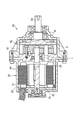
従来の摩擦ローラ式変速機付電動モータとしては、例えば図2〜図3に示したものがある。
【0003】
この摩擦ローラ式変速機付電動モータ20は、電動モータ(第1の電動モータ)30と電動モータ30に接続された摩擦ローラ式変速機40とを備えている。
【0004】
電動モータ30は、モータケース31内に略同心に挿通配置された回転駆動軸32と、回転駆動軸32の外周部に取り付けられたロータ磁石33と、モータケース31の内周面にロータ磁石33と径方向に対向して取り付けられたステータ34とを備えている。回転駆動軸32は、モータケース31の両端壁に設けられた転がり軸受35を介してモータケース31に回転可能に支持されており、一端部がモータケース31の一端壁から突出している。
【0005】
摩擦ローラ式変速機40は、電動モータ30の減速機として機能する。摩擦ローラ式変速機40は、ハウジング41内に配設されている。ハウジング41は、電動モータ30のモータケース31の一端壁にボルト等を介して取り付けられている。摩擦ローラ式変速機40は、モータケース31の一端壁から突出する回転駆動軸32の端部を回転軸とする中心ローラ1と、中心ローラ1の周囲にその回転軸を中心ローラ1の回転軸に対して偏心させた状態で配置されて中心ローラ1に対して相対回転可能とされた外輪2とを備えている。外輪2には、出力軸2aが同心に設けられている。出力軸2aは、ハウジング41に転がり軸受42を介して回転可能に支持されている。
【0006】
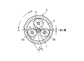
図3は、摩擦ローラ式変速機40の部分断面図である。外輪2に囲まれた内部空間3には、中心ローラ1の外周面及び外輪2の内周面に接する固定ローラ4、可動ローラ5a、及び、固定ガイドローラ5bが備えられている。固定ローラ4、可動ローラ5a、及び、固定ガイドローラ5bは、それぞれ回転可能に構成されており、中心ローラ1の回転力を外輪2に伝達する。
【0007】
固定ローラ4のローラ径は、可動ローラ5a及び固定ガイドローラ5bのローラ径よりも若干大きい。中心ローラ1は、固定ローラ4と可動ローラ5a及び固定ガイドローラ5bとのローラ径の差により、外輪2の中心に関し偏心した状態に位置決めされている。可動ローラ5aは、中心ローラ1と外輪2との間にくさび角θを有する状態で移動可能に保持されている。
【0008】
図3において、中心ローラ1が反時計回りに回転すると、可動ローラ5aは、時計回りに回転する。可動ローラ5aは、中心ローラ1の入力トルクが大きくなるに従って、くさび方向(図3の斜め下方)に入り込み、中心ローラ1と各ローラ4,5a,5bとの間、及び、各ローラ4,5a,5bと外輪2との間に押付力が発生する。この押付力により、トラクション力が発生し中心ローラ1の動力が外輪2に伝達される。この押付力は、入力トルクの大きさに比例するため、入力トルクに応じた適正な押付力を得ることが可能である。
【0009】
一方、出力側から時計回りでトルクが入力された時には、可動ローラ5aはくさび方向から外れる方向(図3の斜め上方)に移動する。この状態では、中心ローラ1と各ローラ4,5a,5bとの間、及び、各ローラ4,5a,5bと外輪2との間に押付力が発生せず動力が伝達されない。
【0010】
上記構成の摩擦ローラ式変速機付電動モータ20によれば、電動モータ30のステータ34に通電することにより、回転駆動軸32は正回転又は逆回転する。ここで、回転駆動軸32の端部で構成される中心ローラ1が図3の矢印A方向に回転する場合には、可動ローラ5aは、くさび方向に移動する。従って、電動モータ30の動力は、各ローラ4,5a,5bを介して外輪2ひいては出力軸2aに効率よく伝達される。
【0011】
一方、中心ローラ1が図3の矢印B方向に逆回転駆動される場合、すなわち、図3の矢印B方向に回転する場合には、可動ローラ5aは、くさび方向から外れる方向に移動する。従って、電動モータ30の動力を入力する中心ローラ1は、空転し、動力は外輪に伝達されない。
【0012】
【発明が解決しようとする課題】
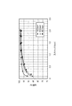
上記従来の摩擦ローラ式変速機付電動モータにおいては、電動モータ30の動力を可動ローラ5aのくさび作用による押し付け力を利用して摩擦ローラ式変速機40側の出力軸2aに伝達している。従って、押し付け力は伝達トルクに比例したものとなり、全負荷領域にわたり良好な伝達効率が得られる。しかしながら、低負荷時、特に高速回転時には、図4に示すように、若干伝達効率が落ちてしまう。
【0013】
本発明は上記課題を解消することに係り、略全ての負荷及び回転速度の範囲で高い伝達効率を得ることができる摩擦ローラ式変速機付電動モータを提供することを目的とする。
【0014】
【課題を解決するための手段】
上記目的を達成するため、本発明の請求項1記載の摩擦ローラ式変速機付電動モータは、摩擦ローラ式変速機と、前記摩擦ローラ式変速機を駆動する第1の電動モータと、前記摩擦ローラ式変速機を駆動する第2の電動モータと、を備え、前記第2の電動モータは、前記摩擦ローラ式変速機と軸方向に対して直交する同一平面上の前記摩擦ローラ式変速機の外周側に内蔵されて、前記第1の電動モータにより駆動される前記摩擦ローラ式変速機の出力軸の負荷及び回転速度に応じて前記出力軸を駆動し、前記第2の電動モータの駆動時に前記第1の電動モータと前記摩擦ローラ式変速機との動力伝達が遮断されることを特徴とする。
【0015】
また、本発明の請求項2記載の摩擦ローラ式変速機付電動モータによれば、前記摩擦ローラ式変速機は、前記第1の電動モータの回転駆動軸の端部を回転軸とする中心ローラと、前記中心ローラの周囲に前記出力軸としての回転軸を前記中心ローラの回転軸に対して偏心させた状態で配置され、前記中心ローラに対して相対回転可能とされた外輪と、前記外輪と前記中心ローラとの間に形成された周方向の幅寸法の異なる環状空間と、前記環状空間の幅寸法の広い領域に配置されてその外周面を前記中心ローラの外周面および前記外輪の内周面に当接させた状態で回転可能な第1の固定ガイドローラと、前記環状空間の幅寸法の狭い領域に配置されてその外周面を前記中心ローラの外周面および前記外輪の内周面に当接させた状態で回転可能な第2固定ガイドローラと、前記環状空間の幅寸法の狭い領域で円周方向に変位可能な可動ローラと、を備え、前記第2の電動モータは、前記外輪の外周部に設けられるロータ磁石と、前記摩擦ローラ式変速機のハウジングの内周面に設けられ、前記ロータ磁石と径方向に対向するステータと、を備え、前記ハウジング内に設けられることを特徴とする。
【0016】
また、本発明の請求項3記載の摩擦ローラ式変速機付電動モータによれば、前記第2の電動モータは、前記出力軸が低負荷でかつ高速回転である場合に駆動される。
【0017】
また、本発明の請求項3記載の摩擦ローラ式変速機付電動モータによれば、前記第2の電動モータは、前記出力軸が高負荷でかつ低速回転である場合には、停止している。
【0018】
上記構成によれば、前記出力軸の負荷が低負荷で高速回転時には前記第2の電動モータを駆動させて前記外輪ひいては出力軸を直接回転駆動させ、高負荷で低速回転時には第2の電動モータを停止させると共に、第1の電動モータの動力を摩擦ローラ式変速機を介して外輪ひいては出力軸に伝達して前記出力軸を回転させ高負荷に耐える出力を行う。
【0019】
ここで、低負荷で高速回転時の第2の電動モータによる出力軸への動力伝達の際には、前記第1の電動モータと前記摩擦ローラ式変速機との動力伝達が遮断される。従って、前記摩擦ローラ式変速機を介しないため、摩擦ローラ式変速機によるトルク損失はなく効率よく動力伝達でき、また、第2の電動モータの速度範囲を広げることができる。
【0020】
このように、出力軸の負荷及び回転速度により第1の電動モータと第2の電動モータとを使い分けることにより、略全ての負荷、回転速度の範囲で高い伝達効率を得ることができる。
【0021】
【発明の実施の形態】
以下、添付図面に基づいて本発明の一実施形態における摩擦ローラ式変速機付電動モータを詳細に説明する。
【0022】
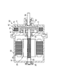
図1は、本発明の一実施形態に係る摩擦ローラ式変速機付電動モータを説明するための断面図である。尚、図2〜図3に示した従来の摩擦ローラ式変速機付電動モータと実質的に同一部分については同符号を付してその説明を省略する。
【0023】
本発明の一実施形態に係る摩擦ローラ式変速機付電動モータ50は、第1の電動モータ30と電動モータ30に接続された摩擦ローラ式変速機60とを備えている。摩擦ローラ式変速機60は、ハウジング61が外輪2との間に所定の間隔をあけて第1の電動モータ30のモータケース31に取り付けられている。
【0024】
外輪2の外周部には、ロータ磁石71が取り付けられている。ハウジング61の内周面には、ロータ磁石71と径方向に対向するステータ72が取り付けられている。ロータ磁石71とステータ72は、ハウジング61内に外輪2を直接回転駆動させる第2の電動モータ70を構成する。第2の電動モータ70はトルクセンサや回転速度センサによって得られた出力軸2aの負荷及び回転速度に応じて駆動される。外輪2の内周側の構造は、図3に示すものと同一である。
【0025】
本実施形態の摩擦ローラ式変速機付電動モータ50では、出力軸2aの負荷が低負荷で高速回転時(例えば図4で回転速度4000rpmでトルクが0.7N・mを下回ったとき)には図示しない制御装置が第2の電動モータ70を駆動し、外輪2ひいては出力軸2aを直接回転駆動する。
【0026】
一方、高負荷で低速回転時には第2の電動モータ70を停止させると共に、第1の電動モータ30の動力を摩擦ローラ式変速機60を介して外輪2ひいては出力軸2aに伝達して出力軸2aを回転させ高負荷に耐える出力を行う。これにより、略全ての負荷、回転速度の範囲で高い伝達効率を得ることができる。
【0027】
低負荷、高速回転時に第2の電動モータ70が出力軸2aへ動力を伝達する場合、第1の電動モータ30の回転駆動軸32の角速度よりも出力軸2aの角速度が上回る。よって、第2の電動モータによる動力伝達時は、図3において、中心ローラ3がB方向に回転する場合と同様の状態となる。従って、可動ローラ5aは、くさび方向から外れる方向に移動する。
【0028】
この結果、可動ローラ5aは、外輪2から退避状態となる。そして、固定ガイドローラ4の中心ローラ1の外周面と外輪2の内周面との間の当接圧も低下し、外輪2から中心ローラ1(回転駆動軸32)への回転駆動力の伝達が断たれる。即ち、第1の電動モータ30と摩擦ローラ式変速機60との動力伝達が遮断される。
【0029】
これにより、第1の電動モータ30及び摩擦ローラ式変速機60が第2の電動モータ70側の駆動力に対する抵抗(トルク損失)になるのが防止され、第2の電動モータ70の出力軸2aへの動力伝達を効率よく行うことができる(高負荷、低速時と同程度の伝達効率95%程度)。また第1の電動モータ30及び摩擦ローラ式変速機60が抵抗として存在しないため、第2の電動モータ70の速度範囲を広げることができる。
【0030】
尚、本発明の摩擦ローラ式変速機付電動モータの第1及び第2の電動モータや摩擦ローラ式変速機の構成は、上記実施形態の構成に限定されるものではなく、本発明の趣旨に基づいて種々の形態を採り得ることができる。
【0031】
【発明の効果】
以上、上述した本発明の摩擦ローラ式変速機付電動モータによれば、出力軸の負荷及び回転速度により第1の電動モータと摩擦ローラ式変速機側の第2の電動モータとを使い分けることにより、略全ての負荷、回転速度の範囲で高い伝達効率を得ることができる。
【図面の簡単な説明】
【図1】本発明の一実施形態に係る摩擦ローラ式変速機付電動モータを説明するための断面図である。
【図2】従来の摩擦ローラ式変速機付電動モータを説明するための断面図である。
【図3】摩擦ローラ式変速機を説明するための断面図である。
【図4】回転速度毎の入力トルクと伝達効率との関係を示すグラフ図である。
【符号の説明】
1 中心ローラ
2 外輪
3 環状空間
4 固定ガイドローラ
5a 可動ローラ
5b 固定ガイドローラ
30 第1の電動モータ
50 摩擦ローラ式変速機付電動モータ
60 摩擦ローラ式変速機
70 第2の電動モータ[0001]
BACKGROUND OF THE INVENTION
The present invention relates to an improvement of an electric motor with a friction roller type transmission incorporated in an electric assist bicycle, an electric vehicle, a hybrid electric vehicle, a fuel cell vehicle, and the like.
[0002]
[Prior art]
Examples of conventional electric motors with friction roller transmissions include those shown in FIGS.
[0003]
The
[0004]
The
[0005]
The
[0006]
FIG. 3 is a partial cross-sectional view of the friction
[0007]
The roller diameter of the
[0008]
In FIG. 3, when the
[0009]
On the other hand, when torque is input clockwise from the output side, the
[0010]
According to the friction roller type transmission-equipped
[0011]
On the other hand, when the
[0012]
[Problems to be solved by the invention]
In the conventional friction roller type transmission-equipped electric motor, the power of the
[0013]
An object of the present invention is to solve the above-described problems, and an object of the present invention is to provide an electric motor with a friction roller type transmission that can obtain high transmission efficiency in almost all load and rotation speed ranges.
[0014]
[Means for Solving the Problems]
In order to achieve the above object, an electric motor with a friction roller type transmission according to
[0015]
According to the electric motor with a friction roller type transmission according to
[0016]
According to the friction roller type transmission-equipped electric motor of the present invention, the second electric motor is driven when the output shaft has a low load and a high speed rotation.
[0017]
According to the friction roller type transmission-equipped electric motor according to
[0018]
According to the above configuration, when the load on the output shaft is low and the high-speed rotation is performed, the second electric motor is driven to directly rotate the outer ring and thus the output shaft. When the load is high and the low-speed rotation is performed, the second electric motor is driven. Is stopped, and the power of the first electric motor is transmitted to the outer ring and then to the output shaft through the friction roller transmission to rotate the output shaft to perform output capable of withstanding high loads.
[0019]
Here, when power is transmitted to the output shaft by the second electric motor during high-speed rotation with a low load, power transmission between the first electric motor and the friction roller transmission is interrupted. Therefore, since the friction roller type transmission is not used, there is no torque loss caused by the friction roller type transmission and power can be transmitted efficiently, and the speed range of the second electric motor can be expanded.
[0020]
Thus, by using the first electric motor and the second electric motor properly depending on the load and rotation speed of the output shaft, high transmission efficiency can be obtained in a range of almost all loads and rotation speeds.
[0021]
DETAILED DESCRIPTION OF THE INVENTION
Hereinafter, a friction roller type electric motor with a transmission according to an embodiment of the present invention will be described in detail with reference to the accompanying drawings.
[0022]
FIG. 1 is a cross-sectional view for explaining an electric motor with a friction roller type transmission according to an embodiment of the present invention. Note that substantially the same parts as those of the conventional friction roller type transmission-equipped electric motor shown in FIGS. 2 to 3 are denoted by the same reference numerals and description thereof is omitted.
[0023]
An
[0024]
A
[0025]
In the
[0026]
On the other hand, the second
[0027]
When the second
[0028]
As a result, the
[0029]
This prevents the first
[0030]
The configurations of the first and second electric motors and the friction roller transmission of the friction roller transmission electric motor according to the present invention are not limited to the configurations of the above-described embodiments, but are within the spirit of the present invention. Various forms can be taken based on this.
[0031]
【The invention's effect】
As mentioned above, according to the electric motor with a friction roller type transmission of the present invention described above, by properly using the first electric motor and the second electric motor on the friction roller type transmission side according to the load and the rotational speed of the output shaft. High transmission efficiency can be obtained in a range of almost all loads and rotational speeds.
[Brief description of the drawings]
FIG. 1 is a cross-sectional view for explaining an electric motor with a friction roller type transmission according to an embodiment of the present invention.
FIG. 2 is a cross-sectional view for explaining a conventional friction roller type transmission-equipped electric motor.
FIG. 3 is a cross-sectional view for explaining a friction roller type transmission.
FIG. 4 is a graph showing the relationship between input torque and transmission efficiency for each rotation speed.
[Explanation of symbols]
DESCRIPTION OF
Claims (4)
前記第2の電動モータは、前記摩擦ローラ式変速機と軸方向に対して直交する同一平面上の前記摩擦ローラ式変速機の外周側に内蔵されて、前記第1の電動モータにより駆動される前記摩擦ローラ式変速機の出力軸の負荷及び回転速度に応じて前記出力軸を駆動し、前記第2の電動モータの駆動時に前記第1の電動モータと前記摩擦ローラ式変速機との動力伝達が遮断されることを特徴とする摩擦ローラ式変速機付電動モータ。An electric motor with a friction roller type transmission comprising: a friction roller type transmission; a first electric motor that drives the friction roller type transmission; and a second electric motor that drives the friction roller type transmission. Because
The second electric motor is incorporated on the outer peripheral side of the friction roller transmission on the same plane perpendicular to the axial direction as the friction roller transmission, and is driven by the first electric motor. The output shaft is driven in accordance with the load and rotation speed of the output shaft of the friction roller transmission, and power is transmitted between the first electric motor and the friction roller transmission when the second electric motor is driven. An electric motor with a friction roller type transmission, characterized in that is interrupted.
前記第1の電動モータの回転駆動軸の端部を回転軸とする中心ローラと、
前記中心ローラの周囲に前記出力軸としての回転軸を前記中心ローラの回転軸に対して偏心させた状態で配置され、前記中心ローラに対して相対回転可能とされた外輪と、
前記外輪と前記中心ローラとの間に形成された周方向の幅寸法の異なる環状空間と、
前記環状空間の幅寸法の広い領域に配置されてその外周面を前記中心ローラの外周面および前記外輪の内周面に当接させた状態で回転可能な第1の固定ガイドローラと、
前記環状空間の幅寸法の狭い領域に配置されてその外周面を前記中心ローラの外周面および前記外輪の内周面に当接させた状態で回転可能な第2固定ガイドローラと、
前記環状空間の幅寸法の狭い領域で円周方向に変位可能な可動ローラと、を備え、
前記第2の電動モータは、前記外輪の外周部に設けられるロータ磁石と、前記摩擦ローラ式変速機のハウジングの内周面に設けられ、前記ロータ磁石と径方向に対向するステータと、を備え、前記ハウジング内に設けられることを特徴とする請求項1記載の摩擦ローラ式変速機付電動モータ。The friction roller transmission is
A central roller having a rotation shaft as an end of the rotation drive shaft of the first electric motor;
An outer ring disposed around the center roller in a state in which a rotation shaft as the output shaft is eccentric with respect to the rotation shaft of the center roller, and is rotatable relative to the center roller;
Annular spaces formed between the outer ring and the central roller and having different circumferential width dimensions;
A first fixed guide roller disposed in a wide region of the annular space and rotatable in a state in which an outer peripheral surface thereof is in contact with an outer peripheral surface of the central roller and an inner peripheral surface of the outer ring;
A second fixed guide roller disposed in a narrow region of the annular space and rotatable in a state in which an outer peripheral surface thereof is in contact with an outer peripheral surface of the central roller and an inner peripheral surface of the outer ring;
A movable roller that is displaceable in a circumferential direction in a region having a narrow width dimension of the annular space , and
The second electric motor includes: a rotor magnet provided on an outer peripheral portion of the outer ring; and a stator provided on an inner peripheral surface of a housing of the friction roller transmission and opposed to the rotor magnet in a radial direction. 2. The friction roller type transmission-equipped electric motor according to claim 1 , wherein the electric motor is provided in the housing .
Priority Applications (1)
| Application Number | Priority Date | Filing Date | Title |
|---|---|---|---|
| JP2002226283A JP4088766B2 (en) | 2002-08-02 | 2002-08-02 | Electric motor with friction roller type transmission |
Applications Claiming Priority (1)
| Application Number | Priority Date | Filing Date | Title |
|---|---|---|---|
| JP2002226283A JP4088766B2 (en) | 2002-08-02 | 2002-08-02 | Electric motor with friction roller type transmission |
Publications (2)
| Publication Number | Publication Date |
|---|---|
| JP2004072843A JP2004072843A (en) | 2004-03-04 |
| JP4088766B2 true JP4088766B2 (en) | 2008-05-21 |
Family
ID=32013676
Family Applications (1)
| Application Number | Title | Priority Date | Filing Date |
|---|---|---|---|
| JP2002226283A Expired - Fee Related JP4088766B2 (en) | 2002-08-02 | 2002-08-02 | Electric motor with friction roller type transmission |
Country Status (1)
| Country | Link |
|---|---|
| JP (1) | JP4088766B2 (en) |
Families Citing this family (2)
| Publication number | Priority date | Publication date | Assignee | Title |
|---|---|---|---|---|
| US7843095B2 (en) | 2005-08-19 | 2010-11-30 | The Timken Company | Friction drive spindle unit |
| JP2013044406A (en) * | 2011-08-25 | 2013-03-04 | Nsk Ltd | Electric transmission and drive device for electric vehicle |
-
2002
- 2002-08-02 JP JP2002226283A patent/JP4088766B2/en not_active Expired - Fee Related
Also Published As
| Publication number | Publication date |
|---|---|
| JP2004072843A (en) | 2004-03-04 |
Similar Documents
| Publication | Publication Date | Title |
|---|---|---|
| JP3480261B2 (en) | Electric vehicle drive | |
| JP5310937B2 (en) | Drive control apparatus for hybrid vehicle | |
| US20120025644A1 (en) | Electric motor having speed change function | |
| WO2011108479A1 (en) | In-wheel motor drive device and design method therefor | |
| JP5817104B2 (en) | Roller friction transmission unit | |
| JP4088766B2 (en) | Electric motor with friction roller type transmission | |
| JP2000050585A (en) | Vehicle drive system | |
| JP4524536B2 (en) | Electric wheel drive device | |
| JP5030006B2 (en) | Motor equipment | |
| JP3245414U (en) | drive unit | |
| JP2008253004A (en) | Vehicle drive device | |
| JP7274079B2 (en) | Roller type differential reducer | |
| JPH07131961A (en) | Electric motor and its control device | |
| CN210309905U (en) | Driving motor assembly for electric vehicle | |
| JP7151967B2 (en) | Driving device and vehicle equipped with it | |
| JP3244940U (en) | drive unit | |
| CN209669537U (en) | Double bevel gear differential speed reduction mechanism for pulsator washing machine | |
| JP3620209B2 (en) | Method for assembling electric motor with friction roller type transmission | |
| JP7597193B1 (en) | Reducer, vehicle, and electric vehicle | |
| JP7697303B2 (en) | Actuator | |
| CN100505481C (en) | Motor unit | |
| KR20090057653A (en) | In-wheel drive system | |
| JP3914207B2 (en) | Transmission | |
| JP2004080868A (en) | Electric motor with friction roller type transmission | |
| JP2006103521A (en) | Electric wheel drive device |
Legal Events
| Date | Code | Title | Description |
|---|---|---|---|
| A621 | Written request for application examination |
Free format text: JAPANESE INTERMEDIATE CODE: A621 Effective date: 20050801 |
|
| RD04 | Notification of resignation of power of attorney |
Free format text: JAPANESE INTERMEDIATE CODE: A7424 Effective date: 20060324 |
|
| A977 | Report on retrieval |
Free format text: JAPANESE INTERMEDIATE CODE: A971007 Effective date: 20071024 |
|
| A131 | Notification of reasons for refusal |
Free format text: JAPANESE INTERMEDIATE CODE: A131 Effective date: 20071031 |
|
| RD04 | Notification of resignation of power of attorney |
Free format text: JAPANESE INTERMEDIATE CODE: A7424 Effective date: 20071128 |
|
| A521 | Written amendment |
Free format text: JAPANESE INTERMEDIATE CODE: A523 Effective date: 20071226 |
|
| TRDD | Decision of grant or rejection written | ||
| A01 | Written decision to grant a patent or to grant a registration (utility model) |
Free format text: JAPANESE INTERMEDIATE CODE: A01 Effective date: 20080130 |
|
| A61 | First payment of annual fees (during grant procedure) |
Free format text: JAPANESE INTERMEDIATE CODE: A61 Effective date: 20080212 |
|
| R150 | Certificate of patent or registration of utility model |
Free format text: JAPANESE INTERMEDIATE CODE: R150 |
|
| FPAY | Renewal fee payment (event date is renewal date of database) |
Free format text: PAYMENT UNTIL: 20110307 Year of fee payment: 3 |
|
| LAPS | Cancellation because of no payment of annual fees |