JP4088743B2 - Tube handling assembly and related methods - Google Patents
Tube handling assembly and related methods Download PDFInfo
- Publication number
- JP4088743B2 JP4088743B2 JP2000524552A JP2000524552A JP4088743B2 JP 4088743 B2 JP4088743 B2 JP 4088743B2 JP 2000524552 A JP2000524552 A JP 2000524552A JP 2000524552 A JP2000524552 A JP 2000524552A JP 4088743 B2 JP4088743 B2 JP 4088743B2
- Authority
- JP
- Japan
- Prior art keywords
- stand
- handling
- well center
- drilling
- pipe
- Prior art date
- Legal status (The legal status is an assumption and is not a legal conclusion. Google has not performed a legal analysis and makes no representation as to the accuracy of the status listed.)
- Expired - Fee Related
Links
Images

Classifications
-
- E—FIXED CONSTRUCTIONS
- E21—EARTH OR ROCK DRILLING; MINING
- E21B—EARTH OR ROCK DRILLING; OBTAINING OIL, GAS, WATER, SOLUBLE OR MELTABLE MATERIALS OR A SLURRY OF MINERALS FROM WELLS
- E21B19/00—Handling rods, casings, tubes or the like outside the borehole, e.g. in the derrick; Apparatus for feeding the rods or cables
- E21B19/14—Racks, ramps, troughs or bins, for holding the lengths of rod singly or connected; Handling between storage place and borehole
- E21B19/143—Racks, ramps, troughs or bins, for holding the lengths of rod singly or connected; Handling between storage place and borehole specially adapted for underwater drilling
-
- E—FIXED CONSTRUCTIONS
- E21—EARTH OR ROCK DRILLING; MINING
- E21B—EARTH OR ROCK DRILLING; OBTAINING OIL, GAS, WATER, SOLUBLE OR MELTABLE MATERIALS OR A SLURRY OF MINERALS FROM WELLS
- E21B19/00—Handling rods, casings, tubes or the like outside the borehole, e.g. in the derrick; Apparatus for feeding the rods or cables
- E21B19/14—Racks, ramps, troughs or bins, for holding the lengths of rod singly or connected; Handling between storage place and borehole
Landscapes
- Engineering & Computer Science (AREA)
- Life Sciences & Earth Sciences (AREA)
- Geology (AREA)
- Mining & Mineral Resources (AREA)
- Mechanical Engineering (AREA)
- Physics & Mathematics (AREA)
- Environmental & Geological Engineering (AREA)
- Fluid Mechanics (AREA)
- General Life Sciences & Earth Sciences (AREA)
- Geochemistry & Mineralogy (AREA)
- Earth Drilling (AREA)
- Automatic Assembly (AREA)
- Supports For Pipes And Cables (AREA)
- Advance Control (AREA)
- Pipeline Systems (AREA)
- Manipulator (AREA)
- Lining Or Joining Of Plastics Or The Like (AREA)
- Specific Conveyance Elements (AREA)
- Switches With Compound Operations (AREA)
- Supporting Of Heads In Record-Carrier Devices (AREA)
Abstract
Description
本発明は、リグ上で使用するパイプ或いはチューブをハンドリングするアッセンブリ及びウェルのセンタにドリル装置を供給するための方法に関する。また、本発明はウェルチューブをリグフロアにハンドリングし、貯蔵するためのウェルデリック構造に関する。
(発明の背景)
従来のリグ設計において、ドリルパイプ、ライザー、キャスティングチューブ等のウェルチューブは、通常メインフロア或いはリグのデッキに存在するラックに積載される単一長のパイプとして貯蔵される。ドリル作業中に用いるウェルチューブのジョイントは、構造上に持ち上げられ、メインリグフロアを、いわゆるキャットウォークと称するドリル或いはリグフロアと接続し、ウェルセンタに隣接するドリルフロアに存在する、いわゆるマウスホールと称する開口部へ下げられる。ジョイントをドリルストリングにジョイントを付加するために、回転台及びケリーからなるドリルストリングの上端は、ドリルストリングの残りの部分から切断され、マウスホール上に移動される。ケリーは、ジョイント(”ボックス”)の上端に突き刺され、接続されたツールジョイントを緊締するために回転される。ケリー及びパイプのジョイントは、ウェルのセンタ上に持ち上げ後方に移動され、吊り下げられたドリルストリングの上端内に突き刺される。再び、緊締された接続は、パイプジョイント及びケリーを回転させることにより緊締される。
ドリルストリングに新しいジョイントを接続した後、ジョイントの長さ分のドリルを開始できる。その後、上記ステップを繰り返すためには、他のジョイントをドリルストリングに付加するために停止しなければならない。
所定の間隔でドリルは停止する。この点において、ドリルストリングはウェルの外へ移動される。移動するために、ケリー及び回転台はドリルストリングの上端から除去され、ドリルフロアにある他の開口部、即ちラットホールの中に配置される。その後、ドリルパイプエレベータは、ドリルストリングを引くのに用いられ、パイプ或いはライザジョイントのスタンド内部に分解する。移動中には、必ずしも単一のチューブジョイントが一時に単一のものに分解されない。その代わり、大抵ドリルストリングは一時に3つのジョイントが引かれる。接続されたパイプのジョイントはいわゆるスタンドを構成する。スタンドは、2つから4つのジョイントの間で変化する。通常スタンドはマスト或いはデリック構造内の鉛直パイプラック内に収容される。スタンドは、基本的に分解作業と反対の作業で再びアッセンブリされる。
初期ドリルストリングとしてキャスティングチューブがアッセンブリされる。しかし、通常キャスティングのためのトリッピング作業は無い。故に、デリック構造体にはケーシングスタンドを収容するためのスペースが無い。
マリンライザーは、キャスティングストリングと非常によく似た方法で動作する。また、ライザージョイントは移動の影響を受けず、通常非常時或いはリグが移動するときにのみ取り出されるため、マスト或いは浮遊ドリルプラットフォームのデリック構造内には、ライザースタンド或いはジョイントは鉛直に収容できない。
近年、パイプジョイントをアッセンブリし、収容するために、例えば電気的に制御された装置を用いて少なくともパイプハンドリングの部分を自動化しようと数多く試みられていた。
上述の活動は、ウェルの建造の経路に沿って発生する。この経路は、クリティカル経路と称される。クリティカル経路で発生する活動はすべて”フラット時間”に起因し、該時間は探鉱にも、ホールの形成にも使われない。故に、本発明は、フラットタイム量を低減し、ウェル形成の効率を向上することを課題とする。
(発明の概要)
本発明の一態様によれば、リグ上で使用するハンドリングアッセンブリを提供し、該ハンドリングアッセンブリは、少なくとも2つのハンドリングステーションを備え、該ハンドリングステーションはチューブを受取りチューブをスタンドとして組立て、組み立てられたスタンドをウェルホールに移送する移送部と、前記ハンドリングステーションは前記ウェルホールのドリル装置から離反して配置される。離反した配置とは、前記ウェルセンタ領域の外側かつケリーの届かない範囲をいう。
前記個々のチューブが前記ドリル装置に到達しないうちに、ケーシング、ドリルパイプ、ライザースタンドなどのチューブをスタンドに前もって組み立てることで、前記クリティカルパスで発生する操作の回数が減り、さらにドリリングに要するフラットタイムを減少させることができる。
前記ハンドリングステーションは、前記ドリル装置のいずれか一方の側に配置され、保存エリアを備え、垂直方向に向けられたスタンドがハンドリングステーションと前記ドリル装置の間に配置されるのが好ましい。これにより、スタンドが、ドリリングの進度とは無関係に形成され、前記ウェルホールへの移送に向けて保存されることが可能となる。また、これにより、チューブのスタンドが前記ドリリング工程とは無関係に前もって組み立てられ、また、前記移送部が、必要に応じて前もって組み立てられたスタンドを単に供給する場合に、前記クリティカルパスの処理にかかるフラットタイムを飛躍的に減少させることが確実にできる。
前記ドリル装置は、リグデッキの一方の端に近接して配置され、該デッキの少なくとも中央部の上方のラックに沿って配列された前記チューブを備えるのが、好ましい。コンベアシステムは、チューブを前記ハンドリングステーションに移送し、該コンベアシステムは、ホイストまたはガントリクレーンなどの持ち上げ装置と、チューブを前記ハンドリングステーションに保持するトロリーとを備える。
スタンドがより軽量のケーシングまたはドリルパイプから形成されている場合、前記移送部はパイプラックシステムとなる。しかし、ライザースタンドなどのより大きなチューブのスタンドの場合、前記移送部は、ホイスト装置及びパイプハンドリングアッセンブリを備え、該ホイスト装置は前記ライザースタンドがウェルセンタに移送される際に該ライザースタンドの重量を支持し、前記パイプラックシステムは前記ホイストと協動し、前記ライザースタンドの横方向のガイドをなす。
本発明により、2つのライザースタンドから成るライザースタンドを形成し、また時間を長くかけることで2つまたは3つ以上のライザースタンドの組立のみを一度に行い、ライザースタンドをウェルホールに直結することで、前記クリティカルパスにおけるフラットタイムをかなり短縮することができる。
ハンドリングステーションは、それぞれ、全3つの小口を有する小口を備え、また前記ウェルセンターの小口を備える。従来の小口とは異なり、前記新型ハンドリングアッセンブリの該小口のうち少なくとも1つは、より大きな直径のケーシング及び/またはライザースタンドに適合するくらいの直径を有する。前記小口は、さらに、従来の小口よりも深い。該小口の深さは、少なくとも2つのパイプジョイント、または少なくとも1つのケーシング、好ましくは3つのパイプジョイントまたは2つのケーシングを越える長さである。
本発明の他の態様よると、3つ又はそれ以上のケーシングから成るケーシングスタンドが提供される。
前記ハンドリングアッセンブリで、2対のライザースタンド及び3対のケーシングスタンドを組み立てて移送することができるのは、前記フラットタイムを縮小するという点で大きな利点である。明細書については、前記設備はこれらのスタンドを移送するのに必ず必要であるが、そうするとさらに重量がかかる。従って、前記ハンドリングアッセンブリにさらに設備が必要である点でコストはかかるが、フラットタイムが全体的に短縮し、ホール形成または引き外し速度が増す。このことは、全体としてはより大きなコスト効果が得られることおw意味する。
本発明の他の態様によれば、ウェルセンタのドリル装置にチューブのスタンドを供給する方法であって、
1) チューブを第1ハンドリングステーション及び第2ハンドリングステーションに移送し、該ハンドリングステーションはウェルセンタの異なる側に設置され、
2) チューブを前記第1ハンドリングステーションでスタンドに組み込み、同時にウェルセンタでドリリングを行い、
3) 前記組み立てられたスタンドをドリル装置に移送する、
工程を備えた方法が提供される。
従って、前記方法によって、ドリリングを行う傍らスタンドの組み込みを続けることができ、ウェルセンタでの作業が実質的に不要となり、その結果、直接ホール形成を行う必要がなくなる。このようにして、一方のハンドリングステーションがスタンドを組み立て、その一方で、もう片方のハンドリングステーションが、スタンドの組み立てとウェルセンタでのドリリングを同時に行うか、またはドリリングに関連する代替作業を行う。従って、前記方法は、チューブを前記第1及び第2ハンドリングステーションの両方のスタンドに組み込み、同時にウェルセンタでドリリングを行う工程から成っていてもよい。
また、前記方法は、スタンドを一方のハンドリングステーションからウェルセンタへ移動し、同時に、もう片方のハンドリングステーションでスタンドを組み立てる工程から成っていてもよい。
前記方法は、ハンドリングステーションとウェルセンタの間の位置にスタンドを保存する工程を含んでいてもよい。この工程により、確実に、スタンドが常時前もって組み立てられ、下向孔を使用できる。これによって、必要に応じてドリリングを行う前に、スタンドを形成し蓄積することができる。
本発明のこれらの及び他の特徴、好ましい実施形態及びその変形、可能な応用及び利点について、当業者は、以下の詳細な説明及び図面によって認識し理解するだろう。
(発明の実施形態)
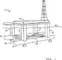
図1には、本発明に関するハンドリングアッセンブリを有する半潜水型リグ10が示されている。前記リグ10は、4本の支柱14、15で2つのポンツーン16に取り付けられたデッキエリア12を有する。前記支柱14、15及びポンツーン16は互いに相互接続され、2つの十字構造20によって固定されている。油井デリック22は、デッキエリア12の前方に向かって設置されているヘリポート24を有するデッキの後方又は船尾に設置されている。
ハンドリングアッセンブリの平面図が図2に示されている。前記ポンツーンの前記原動力の取り外しによって、前記油井デリック22の近くでは広いデッキスペースが利用できる。平面図には油井デリックは示されていないが、ウェルセンタ30及び関係するドリル装置32が示されている。前記ハンドリングアッセンブリは、ウェルセンタ30の反対側に離れて位置する2つのハンドリングステーション34、35、2つのコンベヤ36、38、2つのパイプラッキングシステム40、42及び2つのパイプハンドリングマシン44、46を有し、チューブがウェルセンタ30に達する2つの経路を提供する。保存エリアは各ハンドリングステーション及び前記ドリル装置の間に設けられている。2つのそれぞれの経路の働きは同じなので、前記ハンドリングアッセンブリの働き及び構成要素は、1つの経路に関して、即ちコンベヤ36、ハンドリングステーション34及びパイプハンドリングマシン44を含む経路に関してのみ説明される。前記パイプラッキングシステム40、42は両経路に共通である。
前記ハンドリングアッセンブリを動かす前に、前記チューブ即ちライザー、ドリルパイプ、ドリルカラー及びケースは、デッキ上で、デッキの中心に向かって位置するラックに保存される。ライザーは、セクション52で供給される直径の異なるケースと共に、セクション50に置かれる。前記ケースの直径は30インチから5.5インチまである。ドリルパイプは、ドリルカラー56と共にセクション54に示されている。
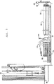
最初の経路に関して、前記パイプラッキングシステムは2つのパイプラックハンドリングマシン40、42を有し、両方共チューブを保存ラック60、62から前記コンベヤ36まで運ぶために使用される。図3に示されているように、前記2つのマシンは異なるタイプの異なる重量のチューブを扱えるように、異なる配置にある。第1パイプラックハンドリングマシン40は、ライザー68の両終端に挿入される外側に動く指64、66を持つオーバーヘッドクレーンから形成されている。このマシンでライザーのセクションを持ち上げるために、前記指64、66は前記ライザーまで下げられ、前記ライザー68の中心口径に挿入され、それをつかむために外側に広げられ、そして前記クレーンが、保存ラック60から前記ライザーを取り出すために持ち上がり、レール74上のトロリーに到るまでレール70に沿って移動し、その上でクレーンは前記指64、66即ち前記ライザーを降ろし、そして一旦前記ライザーが前記トロリーに置かれたら、前記指を引っ込める。
軽量のケース及びドリルパイプに関しては、PiPe Mite(商標名)のような第2パイプラックハンドリングマシン42が使用される。このマシン42は、ラック62に示されるドリルパイプ又はケースのセクションをつかみ、持ち上げ、それらをコンベヤ36上のトロリーの上に置く、可動アーム70を有する。マシン42はレール72に沿って動き、このマシンの使用で第2のオーバヘッドクレーンを使用する必要がない。
前記コンベヤ36は、ライザー、ケース及びドリルパイプのような前記チューブを、前記ハンドリングステーション34に運び、前記レール74の最もハンドリングステーションに近い終端に、トロリーを支持するガイドレール74及びシザーレイザー76を有する。前記レール74は、前記デッキエリアに沿って平坦な経路を進み、一般的に油井デリックを支持する前記プラットホーム80はレール74を支持するデッキ部分から持ち上げられているので、各トロリーをドリル作業プラットホームの高さに持ち上げるために、シザー(はさみ型)レイザー76が装備されている。
前記ハンドリングステーション34は、コンベヤトロリー84からチューブを持ち上げるためのホイスト82、下方の支柱の中に導く仮の小口86、二重ラフネック及び該ラフネック用のターンテーブルを備える。前記ダブルラフネック90は、違ったサイズのチューブをつなげることができるように、直径の異なる2対のトングを有する。しかし、明らかな代替として、異なる直径のトングを持つ2つの分離したラフネックが提供され得る。図2において、前記パイプハンドリングマシン44は前記ハンドリングステーション86に示されているが、それはレール92に沿って、前記ハンドリングステーション86と前記ウェルセンタ30の間を、後述するように動く。前記パイプハンドリングマシン44は、改良された重量物の持ち上げと安全特性のために、3つの角を持つ伸長可能なアーム94、96及び98を有する。
ハンドリングステーション34及びパイプハンドリングアッセンブリ44は、チューブ、即ち、2以上の接続された管状部品のスタンド(起立体)を、前記コンベヤーに沿って供給されたチューブから組み立てる。一旦、スタンドが組み立てられると、それらは、保存エリア100、102に保存され、必要に応じてウェルセンター30に供給するために準備される。保存エリア100,102,104,106は、2つのラック、即ち、ライザーのスタンドのための高いラックと、ケーシング及びパイプ接続のスタンドのための低いラックとである。高いラックは可動指状部を有し、その可動指状部は、ライザーのスタンドを支持するために延設されているが、ドリルパイプのスタンド及びケーシングのスタンドの保存が必要とされる時には、低いラックへにアクセスできるように引っ込む。何れのスタンドが保存エリア100,102,104,106に保存されるかは、掘削された井戸の深さによるだろうし、掘削の初期の段階では、前記保存エリアは、ライザーのスタンドによって占拠されており、掘削の中期段階では、異なる直径及び異なる方向を向いたケーシングのスタンドによって占拠されており、掘削の最終段階では、ドリルパイプで占拠されちている。
ライザー、ケーシング、及びドリルパイプのスタンドを製作するために操作アッセンブリの使用について、コンベヤ36,ハンドリングステーション34、パイプラッキングシステム40,42、及びパイプハンドリングアッセンブリ44を含む輸送経路を参照して記述する。
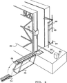
ライザー、ケーシング、或いはドリルパイプ等のチューブの各々の区域は、最初に、保存エリア50,52,54,56から、上述及び図3に示されているようなパイプラッキング装置40,42を用いることによって、ガイドレール74上のトロリーに運ばれる。1本又は2本以上のチューブは、各々のトロリーに載置され、そのトロリーが必要な本数のチューブをその上に載置した時に、該トロリーがガイドレール74に沿って、挟み持ち上げ機76の上までに移動する。そこで挟み持ち上げ機76は、図4に示されているように、トロリー84を、デリック(起重機)を搭載している掘削プラットフォーム80の高さまで持ち上げ、それによりハンドリングステーション34と同じ高さに持ち上げられる。
ハンドリングステーション34では、前記チューブは、スタンドに組み立てられ、それらのスタンドは、前記パイプハンドリングアッセンブリによって搬送され、そこでデリック上のホイスト(巻上げ機)と共同して、保存エリア100,102に充当される。
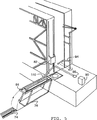
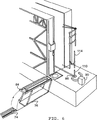
トロリー84が一旦持ち上げられると、補助ホイスト82が降ろされ、その掛止機構が、図5に示すように、チューブ110を掴む。ホイスト82は持ち上げられて、チューブ110が、水平位置から垂直位置に上昇させられ、適切な停止装置を用いて十分な作業高さにおいて吊り下げられる。パイプハンドリングアッセンブリ44は、その下方のアーム94を延ばして、吊り下げられたチューブ110を把持するとともに支持し、ホイスト82は、チューブ110の把持を解除する。パイプハンドリングアッセンブリ44は、チューブ110を上昇させ、ターンテーブル112上で回転させてチューブ110を小口に配置し、小口86によって挟持されるまで下方へ降ろす。このステップは、他のチューブ114を用いて繰り返される。図6に示すように、2番目のチューブ114が、1番目のチューブの天端に進められ、ラフネック90が、レールに沿って移動し、小口86に達し、そのトング(挟み具)を用いて2本のチューブを互いに接続させる。ラフネック90は、可変径の2本のトングを持って、異径のケーシングやパイプ接続に対処する。
ケーシングのスタンドを組み立てる時、この操作は、ケーシングの3セクションがラフネック90によってトリプルスタンドに組み立てられるまで繰り返される。ドリルパイプをスタンドに組み立てるとき、前記操作は、ドリルパイプの各々の3つのセクションが、トリプルスタンドに組み立てられるまで、或いは、ドリルパイプの4つのセクションが、ラフネック90によってフォーブル(fourble)スタンドに互いに接続されるまで、繰り返される。ライザーがスタンドに組み立てられるとき、これは、ライザーの2つのセクションからなるダブルスタンドのみである。2本のライザーを互いに接続する際、ラフネック90ではこの接続ができないので、人手による接続が要求される。
パイプ及びケーシングのスタンドが一旦組み立てられると、パイプハンドリングアッセンブリ44は、その3本のアーム94,96,98を回転させつつ延ばして、そのスタンドを掴み、それを小口86から引き出す。アーム94,96,98は、そこで、パイプハンドリングアッセンブリ44の中央軸に向けて運ばれ、ターンテーブル112回りに回転し、スタンドをレール92に沿って搬送する。前記スタンドは、ウェルセンター30に向けて分配されるか、或いは、必要時の使用のための用意された保存エリア100,102に配置される。
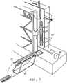
そこでは、パイプハンドリングアッセンブリ44は、ライザーのスタンド重量を運ぶことができないので、ライザーのスタンドは、小口86内にあり、ライザー116のスタンドは、ホイスト120によって、デリック内のブリッジクレーンから小口86の外へ上昇させられる。デリックホイスト120の下部は、図7に見ることができる。一旦、ダブルライザースタンド116が小口86から取り出させれると、ホイスト120及びパイプハンドリングアッセンブリ44は、レール92の方向に沿って縦に移動し、パイプハンドリングアッセンブリ44は、スタンド116の横方向案内を与えるように作動する。しかしながら、スタンドの重量は、ホイスト120によって支持される。前述の通り、前記スタンドがウェルセンター30の方向に分配されるか、或いは、使用の用意のための保存エリア100,102内に配置される。
ウェルセンターの近傍では、孔を掘削するための掘穿装置32は、搬送システム、ラフネック、及び付属ターンテーブルを含み、それらが図示されている。ドリルパイプスタンド120,122は、ウェルセンターの側部に、異なる形態をした底孔アッセンブリ(BHA)124,126を備える。吹き出し防止物(BOPs)も、その近傍に保存されている。
新たなライザー、パイピング又はケーシングが、ウェルホール30への挿入に必要になった時、パイプハンドリング装置44、或いは、パイプハンドリング装置44及びライザースタンドが動かされているデリックホイスト120は、保管エリア100,102からスタンドを持ち上げて、レール92に沿ってウェルセンター30の近傍位置に届くまで移動させる。そして、ドローワーク、ドリリングライン、冠滑車、及び、複数部分のブロックが組み付いた配置の移動ブロックアッセンブリの組み合わせを使用することにより、移動ブロック及びパワースイベルを備える移動システムは、ドリルホール30、及び、ウェルセンター30に配置されたパイプスタンドから持ち上げられる。
パイプハンドリング装置44又はホイスト120は、ウェルセンター30から除去され、そして、移動システムはスタンドの上端と係合するように降下され、ドリル作業は継続される。パイプハンドリング装置の中心線がウェル中心線から十分オフセットするようなウェルオペレーションから独立して、装置44及びホイスト120は、デリック付近のいかなる保管エリアにおいても、スタンドを取り出し又は配置することが可能である。スタンドがウェルセンターから取り出されると、それらはパイプハンドリング装置又は適当なホイストによってセットバックエリアに戻される。
チューブラスタンドは解体可能であり、上述したプロセスを逆にすることにより、デリックの外に置かれる。
ハンドリングアッセンブリは、ホールを作ること、即ち、パイプを持ち上げて降ろすことを直接的には生じさせないウェル建造のクリティカルパスから、活動を実質的に除去し、通常はドリルプロセスと一体化され、こうして、パイプ、ケーシング、ライザー等をクリティカルパスから離れてスタンドに集結可能にすることで、チューブラハンドリング時間において少なくとも50%+の削減が与えられる。必要であれば、ロギングツールストリングやコアバレル等もまた、スタンド(4つ、3つ又は2つ)として保管可能である。これによって、ホールを作るのに費やされない「フラットタイム」における著しい削減が得られる。アッセンブリにおける全ての装置の配置が、アッセンブリにおけるいくつか若しくは全ての機械の共同作用を可能にしているので、削減は、約25%として容易に定量化でき、クリティカルパス全体から活動を除去すること、或いは、並行して行う活動の数を増やすことでそれらのインパクトを著しく減少させることに起因する機械的な効率において得られるものである。
こうして、ウェルボアが孔あけされている間、及び、ウェルセンタに直接移送されるスタンドにとっては、ハンドリングステーションの1又は双方がスタンドを作っている間、ハンドリングアッセンブリは、ライザースタンド、ケーシングスタンド、ドリルパイプスタンドのようなチューブラスタンドが、双方のハンドリングステーションによって作られるのを可能にする。こうして、スタンドの製造は、双方のハンドリングステーションにおいてドリルにより同時に行うことが可能であり、或いは、もし他方のハンドリングステーションがホールの製造中に他のタスクを行うことを必要とされていれば、スタンドの製造は一方のハンドリングステーションでドリルにより同時に行うことが可能である。
ツリーランニング、サブシー装置及びウエルテスト装置を配置するため、サブシー完成設備は、潜水構造体の左舷側及び右舷側近傍にある専用の長方形保管エリアを含んでいる。更に、BOP及びライザーは、ムーンプールビームに吊されており、ウェル全体を開放水域とする作業が行われている間は、BOPが配置された状態に放置するウェルセンター30から除去される。この特徴はまた、BOPの作動/取り出し時間を短縮して、短い内部動きの間、BOPが配置されたままにすることを可能にする。
次の例は、典型的なディープウォータドリルプログラムを説明するものである。
表面のホールが孔あけされている間、導体ケーシング及び26”BHAが、ハンドリングステーションのいずれかにおいて製造され、作動準備される。
導体がセットされると、26”ホールセクションは、20”ケーシング、17 1/2”BHA及びライザーがラックバックしている間、予め組み立てられた26BHAを用いることにより孔あけされる。更に、17 1/2”ホールセクションマッドが準備される。
20”ケーシングをセットした後、BOPは2つのライザースタンドを用いて520fphを越える速度で作動される。これは、例えば、7500ftの水深において、従来のリグが最大62時間であるのと比較して、約14時間作動可能であることを意味する。BOPがテストされ、セクションが孔あけされている間、13 3/8”ケーシングが持ち上げられ、デリックに移動される。36”及び26”のBHAが配置され、12 1/4”のホールセクションマッドが準備される。
予めテストされたBHAを用いて12 1/4”のホールセクションが孔あけされている間、9 5/8”ケーシングが持ち上げられ、セクションに必要ないずれかのロギングツールに沿ってデリックに移動される。また、8 1/2”ホールセレクションマッドが準備される。更に、もしツリーが作動されると、専用の移送及び保管エリアに準備可能である。
8 1/2”ホールセレクションが孔あけされている間、完成のための7”ライナテストストリングがデリック内を移動される。更に、もし完成が要求されれば、ライザーもまたラックバックされる。もしウェルがテストされると、永久的な設置か一時的なテストかのいずれかの装置が準備される。ライナが一旦セットされると、ウェルは、テスト、或いは、完成していれば完全な作動のいずれかが可能になり、BOPは正常な状態に戻り、ツリーは作動する。
図8から図10は本発明に係るハンドリングステーションの他の実施形態を示し、先に示した図と同じ番号が適宜使用されている。図8に示すアッセンブリにおいて、2つのパイプラックハンドリング装置140及び142が備えられており、はさみ型上昇機に代えて、レール136及び138と結合されたランプ176が備えられている。この実施形態においては、パイプラックハンドリング装置は、図2において参照番号40で示されたものと同じである。第2パイプラックハンドリング装置は、装置140と近似した構造を有するが、より軽いケーシング及びドリルパイプのような重量のより軽いチューブを扱うのに適用される。したがって、装置140に対して、装置142は、水平乃至横方向に移動可能なフィンガを備えたオーバーヘッドクレーンとなる。該フィンガーは、前述の装置40がライザーを持ち上げるのと同様にして、ラック62に示されたケーシング又はドリルパイプの一部を保持して持ち上げる。
パイプハンドリング装置によりチューブの一部が持ち上げられると、クレーンはレール170及び172に沿って移動し、レール136,138に沿って移動可能なトロリー184上にチューブを降ろす。レール136,138は、デッキエリアに沿うフラットパスに従う。そして、図9及び図10示すように、トロリーをドリリングプラットフォームの高さに上昇させるために、ランプ176が備えられている。
トロリー184がランプ176上となり、トロリーの前端がランプの上端に達すると、補助ホイスト82が下降させられ、図4〜図7を参照して概略を説明したように該補助ホイストのラッチメカニズムがチューブを掴む。
【図面の簡単な説明】
【図1】 半潜水型リグの斜視図である。
【図2】 本発明に関するハンドリングアセンブリを示すリグの平面図である。
【図3】 ハンドリングアセンブリで使用されるコンベヤ及パイプラッキングシステムの側面図である。
【図4から7】 操作中の前記アセンブリのハンドリングステーション及びパイプハンドリングマシンを示す。
【図8】 本発明に関する更なるハンドリングアッセンブリを示すリグのデッキの平面図を示す。
【図9及び10】 前記更なるハンドリングアッセンブリで使用される更なるパイプラッキングシステムの側面図を示す。The present invention relates to an assembly for handling pipes or tubes for use on a rig and a method for supplying a drilling device to the center of a well. The invention also relates to a welderic structure for handling and storing a well tube on a rig floor.
(Background of the Invention)
In conventional rig designs, well tubes such as drill pipes, risers, and casting tubes are typically stored as single length pipes that are loaded onto a rack that resides on the main floor or rig deck. The well tube joint used during the drilling work is lifted on the structure, connecting the main rig floor with a drill or rig floor called a so-called catwalk, and an opening called a so-called mouse hole that exists in the drill floor adjacent to the well center Lowered to the department. To add the joint to the drill string, the upper end of the drill string consisting of the turntable and Kelly is cut from the rest of the drill string and moved over the mouse hole. Kelly is pierced at the top of the joint ("box") and rotated to tighten the connected tool joint. The kelly and pipe joints are lifted and moved rearward over the center of the well and pierced into the upper end of the suspended drill string. Again, the tightened connection is tightened by rotating the pipe joint and kelly.
After connecting a new joint to the drill string, you can start drilling for the length of the joint. Thereafter, in order to repeat the above steps, another joint must be stopped to add to the drill string.
The drill stops at a predetermined interval. At this point, the drill string is moved out of the well. To move, the kelly and turntable are removed from the upper end of the drill string and placed in another opening in the drill floor, the rat hole. The drill pipe elevator is then used to pull the drill string and disassembles inside the stand of the pipe or riser joint. During movement, a single tube joint does not necessarily break down into a single one at a time. Instead, most drill strings are pulled three joints at a time. The joints of the connected pipes constitute a so-called stand. The stand varies between two to four joints. Usually the stand is housed in a vertical pipe rack in the mast or derrick structure. The stand is basically reassembled in an operation opposite to the disassembly operation.
A casting tube is assembled as an initial drill string. However, there is usually no tripping work for casting. Therefore, the derrick structure has no space for accommodating the casing stand.
Marine risers operate in a manner very similar to casting strings. Also, the riser joint is not affected by movement and is usually taken out only in an emergency or when the rig moves, so the riser stand or joint cannot be accommodated vertically in the derrick structure of the mast or floating drill platform.
In recent years, many attempts have been made to automate at least the pipe handling portion, for example, using an electrically controlled device, to assemble and house the pipe joint.
The activities described above occur along the path of the well construction. This route is referred to as a critical route. All activities that occur on the critical path are due to "flat time", which is not used for exploration or hole formation. Therefore, an object of the present invention is to reduce the amount of flat time and improve the efficiency of well formation.
(Summary of Invention)
According to one aspect of the present invention, a handling assembly for use on a rig is provided, the handling assembly comprising at least two handling stations, the handling station receiving a tube and assembling the tube as a stand and the assembled stand. And the handling station are arranged away from the drilling device of the well hole. The distant arrangement means a range outside the well center region and not reaching Kelly.
By assembling tubes such as casing, drill pipe and riser stand in advance to the stand before the individual tubes reach the drilling device, the number of operations occurring in the critical path is reduced, and flat time required for drilling is further reduced. Can be reduced.
Preferably, the handling station is arranged on either side of the drilling device, has a storage area, and a vertically oriented stand is arranged between the handling station and the drilling device. Accordingly, the stand can be formed regardless of the progress of drilling and can be stored for transfer to the well hole. This also takes care of the critical path when the tube stand is pre-assembled independently of the drilling process and the transfer unit simply supplies the pre-assembled stand as needed. The flat time can be reduced dramatically.
Preferably, the drilling device comprises the tube disposed adjacent to one end of the rig deck and arranged along a rack above at least the central portion of the deck. The conveyor system transports the tubes to the handling station, the conveyor system comprising a lifting device such as a hoist or gantry crane, and a trolley that holds the tubes in the handling station.
If the stand is formed from a lighter casing or drill pipe, the transfer section is a pipe rack system. However, in the case of a larger tube stand, such as a riser stand, the transfer section comprises a hoist device and a pipe handling assembly, and the hoist device reduces the weight of the riser stand when the riser stand is transferred to a well center. In support, the pipe rack system cooperates with the hoist to provide a lateral guide for the riser stand.
According to the present invention, a riser stand composed of two riser stands is formed, and only two or more riser stands are assembled at a time by taking a long time, and the riser stand is directly connected to the well hole. The flat time in the critical path can be considerably shortened.
Each handling station comprises a forehead having a total of three foreheads and the well center forehead. Unlike conventional foreheads, at least one of the foreheads of the new handling assembly has a diameter sufficient to accommodate a larger diameter casing and / or riser stand. The forehead is further deeper than a conventional forehead. The depth of the forehead is at least two pipe joints, or at least one casing, preferably more than three pipe joints or two casings.
According to another aspect of the present invention, a casing stand is provided comprising three or more casings.
The ability to assemble and transfer two pairs of riser stands and three pairs of casing stands with the handling assembly is a great advantage in terms of reducing the flat time. For the specification, the equipment is absolutely necessary for transporting these stands, but doing so adds weight. Accordingly, the handling assembly is costly in that it requires more equipment, but the flat time is shortened as a whole, and the hole formation or tripping speed increases. This means that a greater cost effectiveness can be obtained as a whole.
According to another aspect of the present invention, a method of supplying a tube stand to a well center drilling apparatus comprising:
1) Transfer the tube to the first handling station and the second handling station, which are installed on different sides of the well center,
2) The tube is incorporated into the stand at the first handling station and simultaneously drilled at the well center.
3) Transfer the assembled stand to a drilling device;
A method comprising the steps is provided.
Therefore, by the above method, it is possible to continue the incorporation of the stand while performing the drilling, and the work at the well center is substantially unnecessary, and as a result, it is not necessary to directly form the hole. In this way, one handling station assembles the stand, while the other handling station assembles the stand and drilling at the well center at the same time, or performs an alternative operation related to drilling. Thus, the method may comprise the steps of incorporating the tubes into the stands of both the first and second handling stations and simultaneously drilling at the well center.
The method may also comprise the steps of moving the stand from one handling station to the well center and simultaneously assembling the stand at the other handling station.
The method may include storing the stand at a location between the handling station and the well center. This process ensures that the stand is always pre-assembled and the down hole can be used. This allows the stand to be formed and stored before drilling as necessary.
These and other features of the present invention, preferred embodiments and variations thereof, possible applications and advantages will be appreciated and understood by those skilled in the art by the following detailed description and drawings.
(Embodiment of the Invention)
FIG. 1 shows a
A top view of the handling assembly is shown in FIG. By removing the driving force of the pontoon, a large deck space is available near the
Prior to moving the handling assembly, the tubes or risers, drill pipes, drill collar and case are stored on the deck in a rack located towards the center of the deck. The riser is placed in section 50 with the different diameter cases supplied in
For the first path, the pipe racking system has two pipe
For lightweight cases and drill pipes, a second pipe
The
The handling station 34 comprises a hoist 82 for lifting the tube from the
The handling station 34 and the
The use of the operating assembly to produce the riser, casing, and drill pipe stand will be described with reference to the transport path including the
Each section of the tube, such as a riser, casing or drill pipe, first uses a
At the handling station 34, the tubes are assembled into stands, which are transported by the pipe handling assembly, where they are allocated to the
Once the
When assembling the casing stand, this operation is repeated until the three sections of the casing are assembled into a triple stand by the
Once the pipe and casing stand is assembled, the
There, the
In the vicinity of the well center, a
When a new riser, piping or casing is required for insertion into the
The
The tubular stand can be disassembled and placed outside the derrick by reversing the process described above.
The handling assembly substantially eliminates activity from the critical path of well construction that does not directly create holes, i.e., lifting and lowering pipes, and is usually integrated with the drilling process, thus By allowing pipes, casings, risers, etc. to be gathered on the stand away from the critical path, at least a 50% + reduction in tubular handling time is provided. If necessary, logging tool strings, core barrels, etc. can also be stored as stands (4, 3 or 2). This provides a significant reduction in “flat time” that is not spent creating holes. Since the placement of all equipment in the assembly allows for the collaboration of some or all machines in the assembly, the reduction can be easily quantified as approximately 25%, removing activity from the entire critical path, Alternatively, it can be obtained in mechanical efficiency due to significantly reducing their impact by increasing the number of activities performed in parallel.
Thus, for wells that are drilled and for stands that are transferred directly to the well center, while one or both of the handling stations make the stand, the handling assembly can be a riser stand, casing stand, drill pipe. A tubular stand, such as a stand, can be made by both handling stations. Thus, the manufacture of the stand can be done simultaneously by drilling at both handling stations, or if the other handling station is required to perform other tasks during the manufacture of the hall. Can be produced simultaneously by drilling at one handling station.
To place the tree running, subsea device, and well test device, the subsea completion facility includes dedicated rectangular storage areas near the port side and starboard side of the diving structure. Further, the BOP and the riser are suspended from the moon pool beam, and are removed from the
The following example illustrates a typical deep water drill program.
While the surface hole is drilled, the conductor casing and 26 "BHA are manufactured and prepared for operation at any of the handling stations.
Once the conductor is set, the 26 "hole section is drilled by using a pre-assembled 26BHA while the 20" casing, 171/2 "BHA and riser are racked back. 1/2 ”hole section mud is prepared.
After setting the 20 "casing, the BOP is operated at speeds exceeding 520 fph using two riser stands. This is, for example, compared to a conventional rig of up to 62 hours at a depth of 7500 ft. This means that it can be operated for about 14 hours. While the BOP is tested and the section is drilled, the 13 3/8 "casing is lifted and moved derrick. 36 ″ and 26 ″ BHA are arranged and 12 1/4 ″ hole section mud is prepared.
While a 12 1/4 "hole section is drilled using a pre-tested BHA, the 9 5/8" casing is lifted and moved derrick along any logging tool required for the section. The Also, an 8 1/2 "hole selection mud is prepared. In addition, if the tree is activated, it can be prepared in a dedicated transfer and storage area.
While the 8 1/2 "hole selection is being drilled, the completed 7" liner test string is moved through the derrick. In addition, if completion is required, the riser is also racked back. If the well is tested, equipment for either permanent installation or temporary testing is prepared. Once the liner is set, the wells can either be tested or, if completed, fully operational, the BOP returns to normal and the tree is operational.
8 to 10 show other embodiments of the handling station according to the present invention, and the same numbers as those used in the above-mentioned drawings are used as appropriate. In the assembly shown in FIG. 8, two pipe rack handling devices 140 and 142 are provided, and a lamp 176 coupled to rails 136 and 138 is provided instead of the scissor type lifting machine. In this embodiment, the pipe rack handling device is the same as that indicated by
As the pipe handling device lifts a portion of the tube, the crane moves along rails 170 and 172 and lowers the tube onto a trolley 184 movable along rails 136 and 138. Rails 136 and 138 follow a flat path along the deck area. 9 and 10, a ramp 176 is provided to raise the trolley to the height of the drilling platform.
When the trolley 184 is on the ramp 176 and the front end of the trolley reaches the top end of the ramp, the auxiliary hoist 82 is lowered, and the latch mechanism of the auxiliary hoist is the tube as outlined above with reference to FIGS. Grab.
[Brief description of the drawings]
FIG. 1 is a perspective view of a semi-submersible rig.
FIG. 2 is a plan view of a rig showing a handling assembly according to the present invention.
FIG. 3 is a side view of a conveyor and pipe racking system used in a handling assembly.
Figures 4 to 7 show the handling station and pipe handling machine of the assembly in operation.
FIG. 8 shows a plan view of a rig deck showing a further handling assembly according to the invention.
9 and 10 show a side view of a further pipe racking system used in the further handling assembly.
Claims (12)
1)ウェルセンタに対して異なる側に位置する第1ハンドリングステーション及び第2ハンドリングステーションにチューブを搬送し、
2)前記第1ハンドリングステーションにおいてチューブをスタンドへと組立、同時にウェルセンタにおいてドリリングを行ない、
3)組み立てられたスタンドをドリル装置に移送する工程を備えた方法。A method of supplying a tube stand to a well center drill device,
1) transport the tubes to the first and second handling stations located on different sides of the well center;
2) Assembling the tube into a stand at the first handling station, and simultaneously drilling at the well center,
3) A method comprising a step of transferring the assembled stand to a drilling device.
Applications Claiming Priority (3)
| Application Number | Priority Date | Filing Date | Title |
|---|---|---|---|
| GBGB9725935.2A GB9725935D0 (en) | 1997-12-08 | 1997-12-08 | Handling assembly and related method |
| GB9725935.2 | 1997-12-08 | ||
| PCT/EP1998/008119 WO1999029999A1 (en) | 1997-12-08 | 1998-12-04 | Handling assembly for tubulars and related method |
Publications (2)
| Publication Number | Publication Date |
|---|---|
| JP2001526342A JP2001526342A (en) | 2001-12-18 |
| JP4088743B2 true JP4088743B2 (en) | 2008-05-21 |
Family
ID=10823282
Family Applications (1)
| Application Number | Title | Priority Date | Filing Date |
|---|---|---|---|
| JP2000524552A Expired - Fee Related JP4088743B2 (en) | 1997-12-08 | 1998-12-04 | Tube handling assembly and related methods |
Country Status (12)
| Country | Link |
|---|---|
| EP (1) | EP1038088B1 (en) |
| JP (1) | JP4088743B2 (en) |
| KR (1) | KR100613926B1 (en) |
| AT (1) | ATE263911T1 (en) |
| AU (1) | AU2271099A (en) |
| CA (1) | CA2313403C (en) |
| DE (1) | DE69823062D1 (en) |
| ES (1) | ES2219933T3 (en) |
| GB (1) | GB9725935D0 (en) |
| NO (1) | NO20002939L (en) |
| PT (1) | PT1038088E (en) |
| WO (1) | WO1999029999A1 (en) |
Families Citing this family (11)
| Publication number | Priority date | Publication date | Assignee | Title |
|---|---|---|---|---|
| KR101056062B1 (en) * | 2009-08-13 | 2011-08-11 | 대우조선해양 주식회사 | How to load and transport risers or drill pipes on rigs and rigs with transverse pipe loading |
| SE536564C2 (en) * | 2012-06-28 | 2014-02-25 | Atlas Copco Rocktech Ab | Device and method for handling drill string components and rock drilling rigs |
| SE536563C2 (en) * | 2012-06-28 | 2014-02-25 | Atlas Copco Rocktech Ab | Device and method for handling drill string components and rock drilling rigs |
| US10145188B2 (en) | 2013-01-25 | 2018-12-04 | Layne Christensen Company | Automated rod manipulator |
| DK178318B1 (en) * | 2013-05-20 | 2015-12-07 | A P Møller Mærsk As | Drilling fluid pipe handling on a drilling rig |
| GB2531951B (en) * | 2013-05-20 | 2018-01-17 | Maersk Drilling As | Riser handling on a drilling rig and a flip and service machine for riser handling on a drilling rig |
| US10012038B2 (en) | 2014-07-15 | 2018-07-03 | Warrior Rig Technologies Limited | Pipe handling apparatus and methods |
| US9394751B2 (en) | 2014-08-28 | 2016-07-19 | Nabors Industries, Inc. | Methods and systems for tubular validation |
| KR102442560B1 (en) * | 2015-12-08 | 2022-09-13 | 대우조선해양 주식회사 | riser transfer device |
| CN107630668B (en) * | 2017-11-01 | 2023-10-20 | 安徽顺乾祥新材料科技有限公司 | Oil pumping tree displacement support |
| US10941649B2 (en) | 2018-04-19 | 2021-03-09 | Saudi Arabian Oil Company | Tool for testing within a wellbore |
Family Cites Families (4)
| Publication number | Priority date | Publication date | Assignee | Title |
|---|---|---|---|---|
| NO144976C (en) * | 1976-04-01 | 1981-12-16 | Golar Nor Offshore As | OUR DEVICE FOR HANDLING AND STORAGE OF RIGS AND DRILLS |
| GB2150962A (en) * | 1983-11-15 | 1985-07-10 | Submarine Eng As | Riser joints handling system on drilling rig structures |
| GB8600053D0 (en) * | 1986-01-03 | 1986-02-12 | Drg Uk Ltd | Off-shore drilling |
| NL9401208A (en) * | 1994-07-22 | 1996-03-01 | Heerema Group Services Bv | Method and device for drilling for oil or gas. |
-
1997
- 1997-12-08 GB GBGB9725935.2A patent/GB9725935D0/en not_active Ceased
-
1998
- 1998-12-04 PT PT98966307T patent/PT1038088E/en unknown
- 1998-12-04 AU AU22710/99A patent/AU2271099A/en not_active Abandoned
- 1998-12-04 KR KR1020007006239A patent/KR100613926B1/en not_active Expired - Fee Related
- 1998-12-04 ES ES98966307T patent/ES2219933T3/en not_active Expired - Lifetime
- 1998-12-04 AT AT98966307T patent/ATE263911T1/en not_active IP Right Cessation
- 1998-12-04 DE DE69823062T patent/DE69823062D1/en not_active Expired - Lifetime
- 1998-12-04 WO PCT/EP1998/008119 patent/WO1999029999A1/en not_active Ceased
- 1998-12-04 EP EP98966307A patent/EP1038088B1/en not_active Expired - Lifetime
- 1998-12-04 CA CA002313403A patent/CA2313403C/en not_active Expired - Lifetime
- 1998-12-04 JP JP2000524552A patent/JP4088743B2/en not_active Expired - Fee Related
-
2000
- 2000-06-08 NO NO20002939A patent/NO20002939L/en not_active Application Discontinuation
Also Published As
| Publication number | Publication date |
|---|---|
| JP2001526342A (en) | 2001-12-18 |
| AU2271099A (en) | 1999-06-28 |
| ES2219933T3 (en) | 2004-12-01 |
| EP1038088A1 (en) | 2000-09-27 |
| WO1999029999A1 (en) | 1999-06-17 |
| WO1999029999A9 (en) | 1999-09-30 |
| CA2313403C (en) | 2007-08-07 |
| EP1038088B1 (en) | 2004-04-07 |
| DE69823062D1 (en) | 2004-05-13 |
| ATE263911T1 (en) | 2004-04-15 |
| CA2313403A1 (en) | 1999-06-17 |
| NO20002939L (en) | 2000-08-08 |
| PT1038088E (en) | 2004-08-31 |
| KR100613926B1 (en) | 2006-08-18 |
| GB9725935D0 (en) | 1998-02-04 |
| NO20002939D0 (en) | 2000-06-08 |
| KR20010032905A (en) | 2001-04-25 |
Similar Documents
| Publication | Publication Date | Title |
|---|---|---|
| US10612323B2 (en) | Simultaneous tubular handling system | |
| US11781384B2 (en) | Drilling installation: handling system, method for independent operations | |
| US6705414B2 (en) | Tubular transfer system | |
| US10760357B2 (en) | Triple activity system and method for drilling operations | |
| AU2007270876B2 (en) | Triple activity drilling ship | |
| EP1753935B1 (en) | Multiple activity rig | |
| JP4088743B2 (en) | Tube handling assembly and related methods | |
| KR101707496B1 (en) | Drill Ship with Auxiliary Structure | |
| US10086917B2 (en) | Drilling vessel and method for operating a drilling vessel adapted to run large diameter casing strings | |
| AU2014201872B2 (en) | Simultaneous tubular handling system | |
| WO2021037361A1 (en) | Arrangement for drilling system, drilling system and method | |
| GB2549258A (en) | Drillship |
Legal Events
| Date | Code | Title | Description |
|---|---|---|---|
| A621 | Written request for application examination |
Free format text: JAPANESE INTERMEDIATE CODE: A621 Effective date: 20051108 |
|
| A131 | Notification of reasons for refusal |
Free format text: JAPANESE INTERMEDIATE CODE: A131 Effective date: 20070808 |
|
| A521 | Request for written amendment filed |
Free format text: JAPANESE INTERMEDIATE CODE: A523 Effective date: 20071029 |
|
| TRDD | Decision of grant or rejection written | ||
| A01 | Written decision to grant a patent or to grant a registration (utility model) |
Free format text: JAPANESE INTERMEDIATE CODE: A01 Effective date: 20080123 |
|
| A61 | First payment of annual fees (during grant procedure) |
Free format text: JAPANESE INTERMEDIATE CODE: A61 Effective date: 20080212 |
|
| R150 | Certificate of patent or registration of utility model |
Free format text: JAPANESE INTERMEDIATE CODE: R150 |
|
| FPAY | Renewal fee payment (event date is renewal date of database) |
Free format text: PAYMENT UNTIL: 20110307 Year of fee payment: 3 |
|
| FPAY | Renewal fee payment (event date is renewal date of database) |
Free format text: PAYMENT UNTIL: 20110307 Year of fee payment: 3 |
|
| FPAY | Renewal fee payment (event date is renewal date of database) |
Free format text: PAYMENT UNTIL: 20130307 Year of fee payment: 5 |
|
| FPAY | Renewal fee payment (event date is renewal date of database) |
Free format text: PAYMENT UNTIL: 20140307 Year of fee payment: 6 |
|
| R250 | Receipt of annual fees |
Free format text: JAPANESE INTERMEDIATE CODE: R250 |
|
| R250 | Receipt of annual fees |
Free format text: JAPANESE INTERMEDIATE CODE: R250 |
|
| R250 | Receipt of annual fees |
Free format text: JAPANESE INTERMEDIATE CODE: R250 |
|
| R250 | Receipt of annual fees |
Free format text: JAPANESE INTERMEDIATE CODE: R250 |
|
| LAPS | Cancellation because of no payment of annual fees |