JP4088741B2 - solenoid valve - Google Patents
solenoid valve Download PDFInfo
- Publication number
- JP4088741B2 JP4088741B2 JP2000049447A JP2000049447A JP4088741B2 JP 4088741 B2 JP4088741 B2 JP 4088741B2 JP 2000049447 A JP2000049447 A JP 2000049447A JP 2000049447 A JP2000049447 A JP 2000049447A JP 4088741 B2 JP4088741 B2 JP 4088741B2
- Authority
- JP
- Japan
- Prior art keywords
- pressure
- passage
- pressure chamber
- valve
- mover
- Prior art date
- Legal status (The legal status is an assumption and is not a legal conclusion. Google has not performed a legal analysis and makes no representation as to the accuracy of the status listed.)
- Expired - Lifetime
Links
Images

Classifications
-
- B—PERFORMING OPERATIONS; TRANSPORTING
- B60—VEHICLES IN GENERAL
- B60K—ARRANGEMENT OR MOUNTING OF PROPULSION UNITS OR OF TRANSMISSIONS IN VEHICLES; ARRANGEMENT OR MOUNTING OF PLURAL DIVERSE PRIME-MOVERS IN VEHICLES; AUXILIARY DRIVES FOR VEHICLES; INSTRUMENTATION OR DASHBOARDS FOR VEHICLES; ARRANGEMENTS IN CONNECTION WITH COOLING, AIR INTAKE, GAS EXHAUST OR FUEL SUPPLY OF PROPULSION UNITS IN VEHICLES
- B60K15/00—Arrangement in connection with fuel supply of combustion engines or other fuel consuming energy converters, e.g. fuel cells; Mounting or construction of fuel tanks
- B60K15/03—Fuel tanks
- B60K15/035—Fuel tanks characterised by venting means
- B60K15/03504—Fuel tanks characterised by venting means adapted to avoid loss of fuel or fuel vapour, e.g. with vapour recovery systems
-
- F—MECHANICAL ENGINEERING; LIGHTING; HEATING; WEAPONS; BLASTING
- F16—ENGINEERING ELEMENTS AND UNITS; GENERAL MEASURES FOR PRODUCING AND MAINTAINING EFFECTIVE FUNCTIONING OF MACHINES OR INSTALLATIONS; THERMAL INSULATION IN GENERAL
- F16K—VALVES; TAPS; COCKS; ACTUATING-FLOATS; DEVICES FOR VENTING OR AERATING
- F16K31/00—Actuating devices; Operating means; Releasing devices
- F16K31/02—Actuating devices; Operating means; Releasing devices electric; magnetic
- F16K31/06—Actuating devices; Operating means; Releasing devices electric; magnetic using a magnet, e.g. diaphragm valves, cutting off by means of a liquid
- F16K31/08—Actuating devices; Operating means; Releasing devices electric; magnetic using a magnet, e.g. diaphragm valves, cutting off by means of a liquid using a permanent magnet
- F16K31/082—Actuating devices; Operating means; Releasing devices electric; magnetic using a magnet, e.g. diaphragm valves, cutting off by means of a liquid using a permanent magnet using a electromagnet and a permanent magnet
-
- Y—GENERAL TAGGING OF NEW TECHNOLOGICAL DEVELOPMENTS; GENERAL TAGGING OF CROSS-SECTIONAL TECHNOLOGIES SPANNING OVER SEVERAL SECTIONS OF THE IPC; TECHNICAL SUBJECTS COVERED BY FORMER USPC CROSS-REFERENCE ART COLLECTIONS [XRACs] AND DIGESTS
- Y10—TECHNICAL SUBJECTS COVERED BY FORMER USPC
- Y10T—TECHNICAL SUBJECTS COVERED BY FORMER US CLASSIFICATION
- Y10T137/00—Fluid handling
- Y10T137/7722—Line condition change responsive valves
- Y10T137/7837—Direct response valves [i.e., check valve type]
- Y10T137/7869—Biased open
- Y10T137/7871—Weight biased
- Y10T137/7874—Edge pivoted valve
Landscapes
- Engineering & Computer Science (AREA)
- General Engineering & Computer Science (AREA)
- Mechanical Engineering (AREA)
- Sustainable Development (AREA)
- Electromagnetism (AREA)
- Life Sciences & Earth Sciences (AREA)
- Physics & Mathematics (AREA)
- Sustainable Energy (AREA)
- Chemical & Material Sciences (AREA)
- Combustion & Propulsion (AREA)
- Transportation (AREA)
- Magnetically Actuated Valves (AREA)
- Lift Valve (AREA)
- Safety Valves (AREA)
Description
【0001】
【発明の属する技術分野】
本発明は、圧力調整弁と開閉弁の機能を兼ねる電磁弁に関する。
【0002】
【従来の技術】
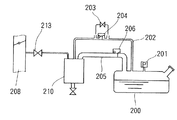
従来の蒸発燃料処理システムに加え、給油中に燃料タンクから発生する蒸発燃料を大気に排出せずキャニスタに吸着させる図7に示すようなORVR(On Board Refueling Vapor Recovery)システムが要求されている。
【0003】
図7に示すORVRシステムにおいて、燃料タンク200とキャニスタ210とを配管202と配管205とが接続している。燃料タンク200にはタンク内圧を検出する圧力センサ201が取り付けられている。電磁弁203は、蒸発燃料の漏れチェックを行うときに開弁し燃料タンク200側とキャニスタ210側とを強制的に連通させる。内圧弁204はダイヤフラムを有し、燃料タンク200内の圧力を所定圧以下に保持する圧力制御弁である。給油弁206はダイヤフラムを有し、燃料タンク200に給油するときに燃料タンク200内の圧力が上昇すると開弁し、蒸発燃料をキャニスタ210側に排出しキャニスタ210に吸着させる。パージ弁213が開弁すると、吸気通路208とキャニスタ210内とが連通する。
【0004】
【発明が解決しようとする課題】
図7に示すようなORVRシステムでは、燃料タンク200とキャニスタ210とを接続する2本の配管202、205、ならびに、電磁弁203、内圧弁204、給油弁206等の多くの弁および配管が必要である。したがって、これら部品の搭載スペースが必要であり、搭載工数も増加するという問題がある。
本発明の目的は、圧力制御弁および開閉弁の機能を兼ねる電磁弁を提供することにある。
【0005】
【課題を解決するための手段】
本発明の請求項1記載の電磁弁によると、コイルへの通電をオフしているときに、第1の圧力室の圧力が第2の圧力室の圧力よりも高くなり、両圧力室の差圧から受圧部材が可動子の往復移動方向の他方に受ける力が第1の付勢手段の付勢力よりも大きくなると、可動子および受圧部材は往復移動方向の他方に移動する。このとき、弁部材が弁座に着座していても弁部材に設けた第1の連通路を介して第1圧力室、つまり第2の通路と第1の通路とは連通する。また、弁部材が弁座から離座していれば、弁部材と弁座との開口を介し第1の圧力室、つまり第2の通路と第1の通路とが連通する。第1の圧力室と第2の圧力室との差圧により受圧部材が移動し第1の通路と第2の通路との連通を断続するので、電磁弁は圧力制御弁として作用する。
【0006】
次に、コイルへの通電をオンし可動子を往復移動方向の他方に移動させると、弁部材から離れて可動子とともに受圧部材が往復移動方向の他方に移動するか、、あるいは弁部材が弁座から離れ可動子とともに受圧部材および弁部材が往復移動方向の他方に移動する。第1の通路と第2の通路とは、第1の連通路、あるいは弁部材と弁座との開口を介して連通する。つまり、コイルへの通電をオンすると、第1の圧力室と第2の圧力室との差圧の大きさに関わらず、第1の通路と第2の通路とが連通する。つまり、電磁弁は電磁開閉弁として作用する。
【0007】
このように、コイルへの通電をオフしているときは圧力制御弁として作動し、コイルへの通電をオンしたときは開閉弁として作動する。一つの電磁弁により圧力制御弁と開閉弁の機能を兼ねているので、圧力制御弁と開閉弁とを別の弁装置にするよりも部品点数が低減し、組付けが容易である。さらに、圧力制御弁と開閉弁とを別の弁装置にするよりも小型化できるので、狭いスペースにも電磁弁を搭載可能である。
【0008】
本発明の請求項2記載の電磁弁によると、受圧部材が第2の圧力室から圧力を受ける受圧面積は、弁部材が第1の通路から圧力を受ける受圧面積とほぼ等しい。したがって、第2の圧力室の圧力と第1の通路の圧力とがほぼ等しい場合、受圧部材が第1の連通路の第1の圧力室側開口と第1の圧力室との連通を遮断し、かつ弁部材が弁座に着座している状態において、受圧部材が第2の圧力室から受ける力と、弁部材が第2の圧力室と反対方向に働く第1の通路から受ける力とを相殺することができる。したがって、電磁弁を閉弁するために必要な第1の付勢手段の付勢力、あるいはコイルに通電することにより可動子とともに受圧部材を往復移動方向の他方に移動させるために必要な磁力を低減可能であり、電磁弁が小型化する。
【0009】
本発明の請求項3記載の電磁弁によると、請求項2記載の構成に加え、受圧部材が第1の連通路の第1の圧力室側開口と第1の圧力室との連通を遮断している状態で、受圧部材は第1の連通路と第2の圧力室とを連通する第2の連通路を有している。第2の圧力室の圧力が第1の通路の圧力と等しくなるので、受圧部材が第2の圧力室から受ける力と、弁部材が第2の圧力室と反対方向に働く第1の通路から受ける力とを相殺することができる。
【0010】
本発明の請求項4記載の電磁弁によると、永久磁石の磁力により可動子が固定子に吸引されることにより受圧部材および弁部材は可動子の往復移動方向の一方である弁座方向に付勢される。したがって、可動子と固定子とが接近した状態で第1の通路と第2の通路との連通を遮断し電磁弁を閉弁できる。可動子と固定子との間に働く磁力による吸引力は可動子と固定子との間に形成されるエアギャップが小さいほど大きくなる。したがって、磁力の小さい永久磁石で大きな閉弁力を得ることができる。また、永久磁石と反発する磁極が固定子に形成されるようにコイルに通電することにより、可動子は固定子から離れる。このときに可動子と固定子との間に働く反発力も、可動子と固定子との間に形成されるエアギャップが小さいほど大きくなる。したがって、コイルが発生する磁力が小さくても可動子が固定子から離れる。コイルの巻数を少なくできるので、電磁弁を小型化できる。
【0011】
【発明の実施の形態】
以下、本発明の実施の形態を示す実施例を図に基づいて説明する。
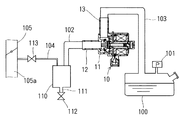
本発明の一実施例による電磁弁を用いたORVRシステムを図2に示す。燃料タンク100とキャニスタ110とを一系統の配管102と配管103とが接続している。電磁弁10のハウジング11に第1接続管12および第2接続管13が形成されている。第1接続管12はキャニスタ110側の配管102と接続しており、第2接続管13は燃料タンク100側の配管103と接続している。圧力センサ101は燃料タンク100内の圧力をチェックし、蒸発燃料の漏れをチェックする。
【0012】
キャニスタ110は蒸発燃料を吸着するものである。電磁弁112が開弁すると、キャニスタ110は配管111を介し大気開放される。キャニスタ110は配管104を介して吸気管105と接続している。配管104に取り付けられているパージ弁113が開弁すると、キャニスタ110内および配管102内と吸気通路105aとが連通する。
【0013】
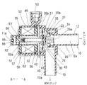
次に電磁弁10の構成を詳細に説明する。
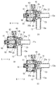
図1に示すように、電磁弁10のハウジング11は樹脂製である。第1接続管12内に第1の通路12aが形成され、第2接続管13内に第2の通路13aが形成されている。第1接続管12のハウジング内側端部に弁座14が形成されている。
【0014】
弁部材20は、弁本体21と、弁座14に着座可能なゴム製の当接部材22とを有している。弁本体21の中央部に弁本体21を貫通し、第1の通路12aと第1の圧力室45とを連通可能な第1の連通路20aが形成されている。第2の付勢手段としてのスプリング23は受圧部材30側に弁部材20を付勢している。
【0015】
受圧部材30は第1の圧力室45と第2の圧力室46とを仕切っている。第1の圧力室45は第2の通路13aと連通している。弁部材20が第1の通路12aから圧力を受ける受圧面積は、受圧部材30が第2の圧力室46から圧力を受ける受圧面積とほぼ等しくなるように設定されている。受圧部材30は、当接側部材31、シャフト側部材32、ゴム製の当接部材33、およびダイヤフラム40を有している。ダイヤフラム40の内周縁は当接側部材31とシャフト側部材32とに挟持され、ダイヤフラム40の外周縁は第1プレート41と第2プレート42とにより挟持されている。当接側部材31とシャフト側部材32との中央部に貫通孔が形成されており、第2の連通路30aを形成している。第2の連通路30aは第2の圧力室46と連通している側孔30bを有している。受圧部材30の当接部材33が弁部材20の第1の連通路20aの外周側に当接すると、第1の連通路20aの第1の圧力室側開口と第1の圧力室45との連通は遮断される。
【0016】
電磁駆動部50は、スプール51に巻回されているコイル52、固定コア55、端部コア56、ヨーク57、および可動子60を有している。コイル52はターミナル53と電気的に接続されている。固定コア55、端部コア56およびヨーク57は磁性材で形成されており固定子を構成している。可動子60は、永久磁石61、樹脂部62およびシャフト63を有している。樹脂部62は、永久磁石61をモールドしており、シャフト63とねじ結合している。ハウジング11の調節孔11aはねじ65で封止され、ねじ65はポッティング樹脂66で固定されている。
コイル52への通電をオフしているとき、永久磁石61の磁力により、可動子60は図1に示す矢印A側、つまり可動子60の往復移動方向の一方に吸引されている。図1はコイル52への通電がオフされている状態を示している。
【0017】
シャフト63の樹脂部62側の端部63aは径方向外側に向け十字状に張り出している。固定コア55の内壁に端部63aと嵌合するように十字状の溝が形成されている。ハウジング11の調節孔11aから治具を挿入し樹脂部62のねじ込み量を調節して永久磁石61と固定コア55との吸引力、つまり電磁弁10の閉弁力を調節する場合、シャフト63の端部63aが固定コア55の十字溝に係止され回転しないので、固定コア55にシャフト63を嵌合した状態で電磁弁10の閉弁力を調節できる。樹脂部62のねじ込み量を調節した後、調節孔11aをねじ65で封止し、ポッティング樹脂66でねじ65を固定する。
【0018】
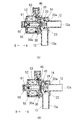
次に電磁弁10の作動について説明する。
(1) コイル52への通電オフ中
図3の(A)に示すように、コイル52への通電オフ中、永久磁石61と固定コア55との間に働く吸引力により、可動子60は矢印A方向に付勢されている。受圧部材30は弁部材20に当接した状態でシャフト63に付勢されている。そして、スプリング23の付勢力に抗し弁部材20は弁座14に着座している。図3の(A)に示す状態では、第1の連通路20aおよび第2の連通路30aを介し第1の通路12aと第2の圧力室46とが連通しているので、第1の通路12aと第2の圧力室46とは同じ圧力である。
【0019】
車両の走行中または停止中に燃料タンク100内の圧力上昇にともない第2の通路13aおよび第1の圧力室45の圧力が上昇すると、第1の圧力室45と第2の圧力室46との差圧から受圧部材30が矢印B方向に受ける力が大きくなり、図3の(B)に示すように、永久磁石61と固定コア55との吸引力に抗し受圧部材30が矢印B方向に移動する。弁部材20は、第1の圧力室45と第1の通路12aとの差圧により弁座14に着座している。受圧部材30は弁部材20から離れることにより、第1の連通路20aを介して第1の圧力室45、つまり第2の通路13aと第1の通路12aとが連通する。第1の通路12aと第2の通路13aとが連通すると、圧力の上昇した燃料タンク100内の蒸発燃料がキャニスタ110側に排出され、キャニスタ110に吸着される。
【0020】
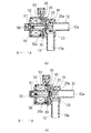
(2) コイル52への通電オン時
(a) ORVRシステム内の蒸発燃料の漏れチェックを行う場合、まず、図5に示すように電磁弁112を開弁し、キャニスタ110を大気開放する。燃料タンク100内の圧力は正圧または負圧のいずれでもよい。次に、図4の(A)に示す閉弁状態から電磁弁10のコイル52への通電をオンにする。コイル52への通電方向は、永久磁石61と対向する固定コア55の端部に永久磁石61との間で反発力が発生する方向に通電する。すると、図4の(B)に示すように、永久磁石61は固定コア55と反発し、可動子60は矢印B方向に移動する。可動子60が矢印B方向に移動すると、スプリング23の付勢力により受圧部材30および弁部材20は矢印B方向に移動する。すると、弁部材20が弁座14から離座し、弁部材20と弁座14との開口を介し、第1の通路12aは第1の圧力室45および第2の通路13aと連通する。
【0021】
第1の通路12aと第2の通路13aとが連通した状態で、図5に示すように電磁弁112を閉弁しパージ弁113を開弁すると、吸気通路105aと、配管102、103、104内および燃料タンク100内とが連通する。そして、配管102、103、104および燃料タンク100に漏れがなければ、燃料タンク100内の圧力は図5に示すように一定の負圧に達する。どこかに漏れがあれば、図5の点線120に示すように燃料タンク100内の圧力は上昇する。このように燃料タンク100内の圧力を検出することにより、ORVRシステムの漏れをチェックすることができる。
【0022】
(b) 燃料タンク100に給油するとき、蓋を開けると電磁弁10のコイル52への通電がオンされるように電気的に接続されている。図6の(A)に示す閉弁状態から燃料タンク100の蓋を開けることによりコイル52への通電をオンすると、図6の(B)に示すように、まず可動子60および受圧部材30が矢印B方向に移動する。燃料給油中、燃料タンク100内の圧力は上昇するので、第2の通路13aの圧力により弁部材20は弁座14に着座したままである。この状態で、第1の連通路20aを介し第1の通路12aと第2の通路13aとは連通する。
【0023】
燃料タンク100内の蒸発燃料が排出され燃料タンク100内の圧力が低下すると、図6の(C)に示すように、弁部材20は弁座14から離座する。すると、弁部材20と弁座14との開口を介し第1の通路12aと第2の通路13aとは連通する。弁部材20が弁座14から離座している、いないに関わらず、第1の通路12aと第2の通路13aとが連通するので、燃料給油中に燃料タンク100内で発生する蒸発燃料はキャニスタ110側に排出され、キャニスタ110に吸着される。
【0024】
本実施例では,可動子60に取り付けた永久磁石61が固定コア55に吸引され、可動子60に付勢される受圧部材30が弁部材20に当接し、弁部材20が弁座14に着座することにより、第1の通路12aと第2の通路13aとの連通を遮断している。
【0025】
これに対し、永久磁石を用いずスプリング等の弾性部材の付勢力で固定コアから離れる方向に可動コアを付勢することにより受圧部材30が弁部材20に当接し、弁部材20が弁座14に着座する構成では、可動コアと固定コアとが離れた状態でコイルに通電し、固定コアに可動コアを吸引しなければならない。したがって、固定コアに可動コアを吸引するためには、大きな磁力が必要となる。大きな磁力を発生するためにはコイルの巻数を増やす必要があるので、電磁駆動部の体格が大きくなる。
【0026】
一方本実施例では、永久磁石61と固定コア55とが接近した状態で第1の通路12aと第2の通路13aとの連通を遮断し電磁弁10を閉弁できる。永久磁石61と固定コア55との間に働く磁力による吸引力は永久磁石61と固定コア55との間に形成されるエアギャップが小さいほど大きくなる。したがって、小さな永久磁石61で大きな閉弁力を得ることができる。また、永久磁石61と反発する磁極が永久磁石61と向き合う固定コア55に形成されるようにコイル52に通電することにより、永久磁石61は固定コア55から離れる。このときに永久磁石61と固定コア55との間に働く反発力も、永久磁石61と固定コア55との間に形成されるエアギャップが小さいほど大きくなる。したがって、コイル52が発生する磁力が小さくても永久磁石61は固定コア55から離れる。コイル52の巻数を少なくできるので、電磁弁を小型化できる
【0027】
以上説明した本発明の上記実施例では、コイル52への通電をオフした状態で、第1の圧力室45と第2の圧力室46との差圧により受圧部材30が移動するので、圧力調整弁として電磁弁10が作動する。コイル52への通電をオンし強制的に弁部材20から離れる方向に受圧部材30を移動させると、弁部材20が弁座14から離座する、しないに関わらず第1の通路12aと第2の通路13aとが連通するので、電磁弁10は開閉弁として作動する。
【0028】
このように、圧力調整弁および開閉弁の両方の機能を兼ねている電磁弁10を例えば本実施例のORVRシステムに用いることにより、燃料タンク100の圧力を一定圧以下に調整する内圧弁、燃料給油中に発生する蒸発燃料をキャニスタ側に排出する給油弁、ならびに蒸発燃料の漏れチェック用の電磁弁の機能を一つの電磁弁10で兼ねることができる。さらに、配管の接続系統が一つになる。したがって、部品点数が減少し、システムの組付けが容易になる。さらに、システムが小型化するので、狭いスペースにも容易に搭載できる。
【0029】
また本実施例では、弁部材20が第1の通路12aから圧力を受ける受圧面積は、受圧部材30が第2の圧力室46から圧力を受ける受圧面積とほぼ等しい。さらに、受圧部材30が第1の連通路20aの第1の圧力室側開口と第1の圧力室45との連通を遮断している状態で、受圧部材30に形成した第2の連通路30aが第1の連通路20aと第2の圧力室46とを連通する。弁部材20に受圧部材30が当接し弁部材20が弁座14に着座している状態において、第2の圧力室46の圧力が第1の通路12aの圧力と等しくなるので、弁部材20が第2の圧力室46と反対方向に働く第1の通路12aから受ける力と、受圧部材30が第2の圧力室46から受ける力とを相殺することができる。
【0030】
(a) 弁部材20が第1の通路12aから圧力を受ける受圧面積が受圧部材30が第2の圧力室46から圧力を受ける受圧面積よりも大きい場合に比べ、永久磁石61の磁力を小さくすることができる。(b) また、受圧部材30が第2の圧力室46から圧力を受ける受圧面積が弁部材20が第1の通路12aから圧力を受ける受圧面積よりも大きい場合に比べ、スプリング23の付勢力を小さくすることができる。したがって、電磁弁10の体格が小さくなる。
【0031】
また本実施例では、磁力により固定コア55に永久磁石61を吸引し、固定コア55と永久磁石61とが接近した状態で第1の通路12aと第2の通路13aとの連通を遮断している。したがって、磁力の小さい永久磁石でも閉弁力を得ることができる。また、永久磁石61との間で反発力が働くようにコイル52に通電することにより、固定コア55から永久磁石61を離している。コイル52の巻数が少なくても電磁弁10を開弁することができるので、電磁弁を小型化できる。
【0032】
本実施例の構成に対し、本実施例の永久磁石61および樹脂部62を磁性材に置き換えて可動コアを構成し、固定コア55に永久磁石を取り付ける構成にすることも可能である。コイル52への通電オフ中は固定コア55に取り付けた永久磁石の磁力により可動コアは固定コア55に吸引される。そして、固定コア55に取り付けた永久磁石の磁束方向と反対方向の磁束が発生するようにコイル52に通電すれば、可動コアと固定コア55との間に働く吸引力が低下し、受圧部材30側に弁部材20を付勢するスプリング23の付勢力により、固定コア55から可動コアを離すことができる。
【0033】
また本実施例の構成に対し、スプリングの付勢力により固定コア55から可動コアを引き離して電磁弁を閉弁し、コイルに通電することにより固定コアに可動コアを吸引する構成にすることも可能である。
本実施例ではORVRシステムに本発明の電磁弁を用いたが、二つの圧力源の間で圧力を調整し、かつ場合によっては強制的に圧力源の間を連通させる構成ならば、本発明の電磁弁を使用可能である。
【図面の簡単な説明】
【図1】本発明の一実施例による電磁弁を示す断面図である。
【図2】本実施例の電磁弁を用いたORVRシステムを示す構成図である。
【図3】コイルへの通電オフ中の電磁弁の作動を示す断面図である。
【図4】蒸発燃料漏れチェック中の電磁弁の作動を示す断面図である。
【図5】蒸発燃料漏れチェック中の各弁の開閉状態および圧力センサの検出信号を示す説明図である。
【図6】燃料給油中の電磁弁の作動を示す断面図である。
【図7】従来のORVRシステムを示す構成図である。
【符号の説明】
10 電磁弁
11 ハウジング
12 第1接続管
12a 第1の通路
13 第2接続管
13a 第2の通路
20 弁部材
20a 第1の連通路
23 スプリング(第2の付勢手段)
30 受圧部材
30a 第2の連通路
45 第1の圧力室
46 第2の圧力室
52 コイル
55 固定コア(固定子)
56 端部コア(固定子)
57 ヨーク(固定子)
60 可動子
61 永久磁石(可動子、第1の付勢手段)
63 シャフト(可動子)[0001]
BACKGROUND OF THE INVENTION
The present invention relates to a solenoid valve that functions as both a pressure regulating valve and an on-off valve.
[0002]
[Prior art]
In addition to the conventional evaporative fuel processing system, there is a demand for an ORVR (On Board Refueling Vapor Recovery) system as shown in FIG. 7 that adsorbs evaporative fuel generated from a fuel tank during refueling to the canister without discharging it to the atmosphere.
[0003]
In the ORVR system shown in FIG. 7, a
[0004]
[Problems to be solved by the invention]
In the ORVR system as shown in FIG. 7, two
An object of the present invention is to provide an electromagnetic valve that also functions as a pressure control valve and an on-off valve.
[0005]
[Means for Solving the Problems]
According to the solenoid valve of the first aspect of the present invention, when the power supply to the coil is turned off, the pressure in the first pressure chamber becomes higher than the pressure in the second pressure chamber, and the difference between the two pressure chambers. When the force that the pressure receiving member receives from the pressure on the other side in the reciprocating direction of the mover becomes larger than the urging force of the first urging means, the mover and the pressure receiving member move to the other side in the reciprocating direction. At this time, even if the valve member is seated on the valve seat, the first pressure chamber, that is, the second passage and the first passage communicate with each other through the first communication passage provided in the valve member. If the valve member is separated from the valve seat, the first pressure chamber, that is, the second passage and the first passage communicate with each other through the opening of the valve member and the valve seat. Since the pressure receiving member moves due to the differential pressure between the first pressure chamber and the second pressure chamber and the communication between the first passage and the second passage is interrupted, the electromagnetic valve functions as a pressure control valve.
[0006]
Next, when energization of the coil is turned on and the mover is moved to the other side in the reciprocating direction, the pressure receiving member moves away from the valve member together with the mover to the other side in the reciprocating direction, or the valve member The pressure receiving member and the valve member move away from the seat to the other side in the reciprocating direction together with the mover. The first passage and the second passage communicate with each other through the first communication passage or the opening of the valve member and the valve seat. That is, when energization of the coil is turned on, the first passage and the second passage are communicated regardless of the magnitude of the differential pressure between the first pressure chamber and the second pressure chamber. That is, the electromagnetic valve functions as an electromagnetic opening / closing valve.
[0007]
As described above, when the energization to the coil is turned off, it operates as a pressure control valve, and when the energization to the coil is turned on, it operates as an on-off valve. Since a single solenoid valve functions as both a pressure control valve and an on-off valve, the number of parts is reduced and assembly is easier than when the pressure control valve and the on-off valve are separate valve devices. Furthermore, since the pressure control valve and the on-off valve can be reduced in size as compared with separate valve devices, an electromagnetic valve can be mounted in a narrow space.
[0008]
According to the electromagnetic valve of the second aspect of the present invention, the pressure receiving area where the pressure receiving member receives pressure from the second pressure chamber is substantially equal to the pressure receiving area where the valve member receives pressure from the first passage. Therefore, when the pressure in the second pressure chamber is substantially equal to the pressure in the first passage, the pressure receiving member blocks the communication between the first pressure chamber side opening of the first communication passage and the first pressure chamber. And the force received by the pressure receiving member from the second pressure chamber and the force received by the valve member from the first passage acting in the opposite direction to the second pressure chamber in the state where the valve member is seated on the valve seat. Can be offset. Therefore, the urging force of the first urging means necessary for closing the solenoid valve or the magnetic force necessary for moving the pressure receiving member in the reciprocating direction together with the mover by energizing the coil is reduced. This is possible, and the solenoid valve is downsized.
[0009]
According to the solenoid valve of the third aspect of the present invention, in addition to the configuration of the second aspect, the pressure receiving member blocks communication between the first pressure chamber side opening of the first communication path and the first pressure chamber. In this state, the pressure receiving member has a second communication path that communicates the first communication path and the second pressure chamber. Since the pressure in the second pressure chamber becomes equal to the pressure in the first passage, the force received by the pressure receiving member from the second pressure chamber and the first passage in which the valve member works in the opposite direction to the second pressure chamber. The force received can be offset.
[0010]
According to the electromagnetic valve of the present invention, the pressure receiving member and the valve member are attached in the valve seat direction, which is one of the reciprocating movement directions of the mover, by the mover being attracted to the stator by the magnetic force of the permanent magnet. Be forced. Therefore, the communication between the first passage and the second passage can be blocked and the solenoid valve can be closed while the mover and the stator are close to each other. The attraction force due to the magnetic force acting between the mover and the stator increases as the air gap formed between the mover and the stator decreases. Therefore, a large valve closing force can be obtained with a permanent magnet having a small magnetic force. Further, when the coil is energized so that a magnetic pole repelling the permanent magnet is formed on the stator, the mover moves away from the stator. At this time, the repulsive force acting between the mover and the stator also increases as the air gap formed between the mover and the stator decreases. Therefore, even if the magnetic force generated by the coil is small, the mover moves away from the stator. Since the number of turns of the coil can be reduced, the solenoid valve can be reduced in size.
[0011]
DETAILED DESCRIPTION OF THE INVENTION
Hereinafter, examples showing embodiments of the present invention will be described with reference to the drawings.
FIG. 2 shows an ORVR system using a solenoid valve according to an embodiment of the present invention. The
[0012]
The
[0013]
Next, the configuration of the
As shown in FIG. 1, the
[0014]
The
[0015]
The
[0016]
The
When the
[0017]
An
[0018]
Next, the operation of the
(1) During energization off of the
[0019]
When the pressure in the
[0020]
(2) When the
(a) When performing a leakage check of the evaporated fuel in the ORVR system, first, as shown in FIG. 5, the
[0021]
When the
[0022]
(b) When refueling the
[0023]
When the evaporated fuel in the
[0024]
In this embodiment, the
[0025]
On the other hand, the
[0026]
On the other hand, in the present embodiment, the communication between the
In the above-described embodiment of the present invention described above, the
[0028]
Thus, by using the
[0029]
In this embodiment, the pressure receiving area where the
[0030]
(a) The magnetic force of the
[0031]
Further, in the present embodiment, the
[0032]
In contrast to the configuration of the present embodiment, the
[0033]
In addition to the configuration of the present embodiment, the movable core is pulled away from the fixed
In this embodiment, the solenoid valve of the present invention is used for the ORVR system. However, if the pressure is adjusted between the two pressure sources and, if necessary, the pressure sources are communicated with each other, the present invention can be used. Solenoid valves can be used.
[Brief description of the drawings]
FIG. 1 is a cross-sectional view showing a solenoid valve according to an embodiment of the present invention.
FIG. 2 is a configuration diagram showing an ORVR system using the solenoid valve of the present embodiment.
FIG. 3 is a cross-sectional view showing the operation of the solenoid valve while the coil is not energized.
FIG. 4 is a cross-sectional view showing the operation of a solenoid valve during a fuel vapor leak check.
FIG. 5 is an explanatory diagram showing an open / close state of each valve and a detection signal of a pressure sensor during an evaporative fuel leakage check.
FIG. 6 is a cross-sectional view showing the operation of the solenoid valve during fuel supply.
FIG. 7 is a block diagram showing a conventional ORVR system.
[Explanation of symbols]
DESCRIPTION OF
30
56 End core (stator)
57 Yoke (stator)
60
63 Shaft (mover)
Claims (4)
前記可動子との間に磁力が作用可能な固定子と、
前記可動子の往復移動方向の一方に前記可動子を付勢する第1の付勢手段と、
通電することにより、前記往復移動方向の他方に前記可動子を移動させる磁力を前記可動子と前記固定子との間に発生させるコイルと、
第1の通路および前記第1の通路と連通可能な第2の通路を有するハウジングと、
前記可動子に対し前記第1の付勢手段の付勢方向側に配置され、前記ハウジング内に形成されている圧力室を前記可動子側の第2の圧力室と前記第2の通路に連通している第1の圧力室とに仕切っている受圧部材と、
前記受圧部材と別部材であり、前記受圧部材に対し前記可動子と反対側に配置され、前記第1の通路と前記第1の圧力室とを連通可能な第1の連通路を有している弁部材と、
前記弁部材が着座可能な弁座であって、前記弁部材が離座すると前記弁部材と前記弁座との開口を介し前記第1の通路と前記第1の圧力室とが連通し、前記弁部材が着座している状態で前記第1の連通路を介し前記第1の通路と前記第1の圧力室とが連通可能な弁座と、
前記受圧部材に向け前記弁部材を付勢する第2の付勢手段とを備え、
前記受圧部材と前記弁部材とが当接することにより前記第1の連通路の前記第1の圧力室側開口は前記第1の圧力室との連通を遮断され、前記受圧部材が前記第1の連通路の前記第1の圧力室側開口と前記第1の圧力室との連通を遮断している状態で前記弁部材が前記弁座に着座すると、前記第1の圧力室と前記第1の通路との連通を遮断することを特徴とする電磁弁。A mover,
A stator capable of acting a magnetic force between the mover, and
First urging means for urging the mover in one of the reciprocating directions of the mover;
A coil that generates a magnetic force between the mover and the stator to move the mover to the other in the reciprocating direction by energization;
A housing having a first passage and a second passage communicable with the first passage;
A pressure chamber disposed in the biasing direction side of the first biasing means with respect to the mover and communicating with the second pressure chamber on the mover side and the second passage is communicated with the pressure chamber formed in the housing. A pressure receiving member partitioned into a first pressure chamber,
The pressure receiving member is a separate member, and is disposed on the opposite side of the movable element with respect to the pressure receiving member, and has a first communication path capable of communicating the first path and the first pressure chamber. A valve member,
The valve member can be seated, and when the valve member is separated, the first passage and the first pressure chamber communicate with each other through an opening of the valve member and the valve seat, A valve seat in which the first passage and the first pressure chamber can communicate with each other via the first communication passage in a state where the valve member is seated;
Second urging means for urging the valve member toward the pressure receiving member;
When the pressure receiving member and the valve member abut, the first pressure chamber side opening of the first communication passage is blocked from communicating with the first pressure chamber, and the pressure receiving member is moved to the first pressure chamber. When the valve member is seated on the valve seat in a state where communication between the first pressure chamber side opening of the communication passage and the first pressure chamber is blocked, the first pressure chamber and the first pressure chamber A solenoid valve characterized in that communication with a passage is cut off.
Priority Applications (2)
| Application Number | Priority Date | Filing Date | Title |
|---|---|---|---|
| JP2000049447A JP4088741B2 (en) | 2000-02-25 | 2000-02-25 | solenoid valve |
| US09/789,841 US6526951B2 (en) | 2000-02-25 | 2001-02-22 | Electromagnetic valve for ORVR system |
Applications Claiming Priority (1)
| Application Number | Priority Date | Filing Date | Title |
|---|---|---|---|
| JP2000049447A JP4088741B2 (en) | 2000-02-25 | 2000-02-25 | solenoid valve |
Publications (2)
| Publication Number | Publication Date |
|---|---|
| JP2001241563A JP2001241563A (en) | 2001-09-07 |
| JP4088741B2 true JP4088741B2 (en) | 2008-05-21 |
Family
ID=18571388
Family Applications (1)
| Application Number | Title | Priority Date | Filing Date |
|---|---|---|---|
| JP2000049447A Expired - Lifetime JP4088741B2 (en) | 2000-02-25 | 2000-02-25 | solenoid valve |
Country Status (2)
| Country | Link |
|---|---|
| US (1) | US6526951B2 (en) |
| JP (1) | JP4088741B2 (en) |
Cited By (2)
| Publication number | Priority date | Publication date | Assignee | Title |
|---|---|---|---|---|
| KR20230036689A (en) * | 2021-09-08 | 2023-03-15 | 주식회사 현대케피코 | Fuel tank isolation valve of vehicle |
| KR20230036687A (en) * | 2021-09-08 | 2023-03-15 | 주식회사 현대케피코 | Fuel tank isolation valve |
Families Citing this family (46)
| Publication number | Priority date | Publication date | Assignee | Title |
|---|---|---|---|---|
| US6814061B2 (en) * | 2002-09-24 | 2004-11-09 | Siemens Vdo Automotive Inc. | Unipolar canister purge valve |
| WO2004079467A1 (en) * | 2003-03-07 | 2004-09-16 | Siemens Vdo Automotive Inc. | An improved integrated pressure management apparatus |
| WO2004113714A1 (en) | 2003-06-20 | 2004-12-29 | Siemens Vdo Automotive Inc. | Purge valve including a dual coil annular permanent magnet linear actuator |
| US6941934B2 (en) * | 2003-06-20 | 2005-09-13 | Siemens Vdo Automotive Inc. | Purge valve including an annular permanent magnet linear actuator |
| WO2004113712A2 (en) * | 2003-06-20 | 2004-12-29 | Siemens Vdo Automotive Inc. | Purge valve including a permanent magnet linear actuator |
| JP4203906B2 (en) | 2004-03-31 | 2009-01-07 | 株式会社デンソー | Solenoid valve and evaporative fuel processing system using the same |
| US7011076B1 (en) | 2004-09-24 | 2006-03-14 | Siemens Vdo Automotive Inc. | Bipolar valve having permanent magnet |
| JP2006153231A (en) * | 2004-12-01 | 2006-06-15 | Denso Corp | Actuator manufacturing method |
| JP2006258283A (en) * | 2005-02-18 | 2006-09-28 | Denso Corp | Fluid control valve and solenoid valve |
| JP2006258135A (en) * | 2005-03-15 | 2006-09-28 | Denso Corp | solenoid valve |
| DE102006022561A1 (en) * | 2006-05-15 | 2007-11-22 | Nass Magnet Gmbh | magnetic valve |
| US8465266B2 (en) * | 2007-10-12 | 2013-06-18 | United Technologies Corp. | Vacuum pressure systems |
| US8573255B2 (en) | 2009-04-22 | 2013-11-05 | Eaton Corporation | Valve assembly for high-pressure fluid reservoir |
| USD706389S1 (en) | 2010-03-30 | 2014-06-03 | Eaton Corporation | Fuel tank isolation valve |
| US8584704B2 (en) * | 2009-04-22 | 2013-11-19 | Eaton Corporation | Valve assembly for high-pressure fluid reservoir |
| US9371803B2 (en) | 2009-04-22 | 2016-06-21 | Eaton Corporation | Valve assembly |
| KR101102462B1 (en) * | 2009-12-29 | 2012-01-05 | 주식회사 인팩 | High frequency pneumatic solenoid valve |
| JP5456493B2 (en) | 2010-01-13 | 2014-03-26 | 愛三工業株式会社 | Solenoid valve and evaporative fuel processing apparatus equipped with the solenoid valve |
| US9500291B2 (en) | 2010-03-30 | 2016-11-22 | Eaton Corporation | Isolation valve with fast depressurization for high-pressure fuel tank |
| US8944100B2 (en) | 2010-03-30 | 2015-02-03 | Eaton Corporation | Isolation valve with fast depressurization for high-pressure fuel tank |
| USD706390S1 (en) | 2010-03-30 | 2014-06-03 | Eaton Corporation | Fuel tank isolation valve |
| USD829304S1 (en) | 2010-03-30 | 2018-09-25 | Eaton Intelligent Power Limited | Valve carriage |
| KR101197453B1 (en) * | 2010-09-29 | 2012-11-05 | 현대자동차주식회사 | Fuel tank valve structure of hybrid car controlling emission gas |
| US20150034180A1 (en) * | 2013-08-02 | 2015-02-05 | Continental Automotive Systems, Inc. | Tank pressure control solenoid with passive tank vacuum relief |
| JP2016527145A (en) * | 2013-08-05 | 2016-09-08 | イートン コーポレーションEaton Corporation | Fuel tank check valve |
| US9902258B2 (en) * | 2015-04-27 | 2018-02-27 | Stant Usa Corp. | Fuel tank pressure regulator |
| CN105422964B (en) * | 2015-12-24 | 2017-08-25 | 江苏奥力威传感高科股份有限公司 | A kind of fuel tank isolation valve |
| CN105402050B (en) * | 2015-12-24 | 2018-02-06 | 江苏奥力威传感高科股份有限公司 | A kind of fuel tank isolation solenoid valve |
| CN109311388B (en) * | 2016-04-15 | 2022-05-31 | 伊顿智能动力有限公司 | Vapor impermeable solenoid valve for fuel vapor environments |
| US10458366B2 (en) | 2016-10-31 | 2019-10-29 | Stant Usa Corp. | Fuel tank pressure regulator |
| KR101944984B1 (en) * | 2017-07-28 | 2019-02-01 | 주식회사 인팩 | Switchable solenoid valve assembly for air spring for changing drive mode in suspension system |
| KR101944990B1 (en) * | 2017-07-28 | 2019-02-01 | 주식회사 인팩 | Switchable solenoid valve assembly for air spring for changing drive mode in suspension system |
| KR101944993B1 (en) * | 2017-07-28 | 2019-02-01 | 주식회사 인팩 | Switchable solenoid valve assembly for air spring for changing drive mode in suspension system |
| KR101944974B1 (en) * | 2017-07-28 | 2019-02-07 | 주식회사 인팩 | Switchable solenoid valve assembly for air spring for changing drive mode in suspension system |
| CN107830182A (en) * | 2017-11-16 | 2018-03-23 | 厦门建霖健康家居股份有限公司 | A kind of magnetic valve with magnet |
| KR102043966B1 (en) * | 2018-03-29 | 2019-11-12 | 주식회사 인팩 | Solenoid valve assembly for switching drive mode in suspension system |
| EP3569904B1 (en) * | 2018-05-18 | 2020-11-04 | Fas Medic S.A. | Valve assembly |
| US10794335B2 (en) | 2018-06-01 | 2020-10-06 | Stant Usa Corp. | Fuel tank pressure regulator |
| CN110397748B (en) * | 2019-08-09 | 2024-08-27 | 东风富士汤姆森调温器有限公司 | Magnetic valve for ventilation of carbon tank |
| WO2021163647A1 (en) | 2020-02-14 | 2021-08-19 | Stant Usa Corp. | Fuel tank pressure regulator |
| DE102020112584A1 (en) * | 2020-05-08 | 2021-11-11 | Pierburg Gmbh | Solenoid valve for venting and degassing a fuel tank of an internal combustion engine |
| CN113983227A (en) * | 2020-07-27 | 2022-01-28 | 纬湃汽车电子(芜湖)有限公司 | Magnetic carbon tank electromagnetic valve and manufacturing method thereof |
| CN116075632A (en) * | 2020-09-07 | 2023-05-05 | 戴科知识产权控股有限责任公司 | Magnetic latching valve for fuel vapor management system and system including same |
| KR102895305B1 (en) * | 2021-03-26 | 2025-12-03 | 현대자동차주식회사 | Fuel tank isolation solenoid valve for vehicle |
| KR102684991B1 (en) * | 2022-06-13 | 2024-07-12 | 주식회사 현대케피코 | Fuel tank isolation solenoid valve |
| US11945298B2 (en) * | 2022-09-01 | 2024-04-02 | Delphi Technologies Ip Limited | Fuel tank isolation valve and related method of use |
Family Cites Families (7)
| Publication number | Priority date | Publication date | Assignee | Title |
|---|---|---|---|---|
| US4988074A (en) * | 1988-05-17 | 1991-01-29 | Hi-Ram, Inc. | Proportional variable force solenoid control valve |
| US5020771A (en) * | 1989-01-26 | 1991-06-04 | Ranco Japan Ltd. | Proportional control valve |
| JPH0741881Y2 (en) * | 1991-04-27 | 1995-09-27 | 東洋電装株式会社 | Evaporative fuel control valve device |
| DE4326838C2 (en) * | 1993-08-10 | 1996-01-11 | Interelektrik Ges M B H & Co K | Bistable solenoid valve |
| JPH07233882A (en) | 1994-02-22 | 1995-09-05 | Nippondenso Co Ltd | Solenoid valve |
| JPH0893576A (en) | 1994-09-26 | 1996-04-09 | Nippondenso Co Ltd | Vapor fuel control valve device |
| CN1109943C (en) * | 1996-11-14 | 2003-05-28 | 福克斯保罗埃卡特股份有限公司 | current pressure converter |
-
2000
- 2000-02-25 JP JP2000049447A patent/JP4088741B2/en not_active Expired - Lifetime
-
2001
- 2001-02-22 US US09/789,841 patent/US6526951B2/en not_active Expired - Lifetime
Cited By (5)
| Publication number | Priority date | Publication date | Assignee | Title |
|---|---|---|---|---|
| KR20230036689A (en) * | 2021-09-08 | 2023-03-15 | 주식회사 현대케피코 | Fuel tank isolation valve of vehicle |
| KR20230036687A (en) * | 2021-09-08 | 2023-03-15 | 주식회사 현대케피코 | Fuel tank isolation valve |
| KR102573761B1 (en) | 2021-09-08 | 2023-08-31 | 주식회사 현대케피코 | Fuel tank isolation valve |
| KR102585781B1 (en) * | 2021-09-08 | 2023-10-05 | 주식회사 현대케피코 | Fuel tank isolation valve of vehicle |
| US11913566B2 (en) | 2021-09-08 | 2024-02-27 | Hyundai Kefico Corporation | Fuel tank isolation valve or vehicle |
Also Published As
| Publication number | Publication date |
|---|---|
| US20010017160A1 (en) | 2001-08-30 |
| US6526951B2 (en) | 2003-03-04 |
| JP2001241563A (en) | 2001-09-07 |
Similar Documents
| Publication | Publication Date | Title |
|---|---|---|
| JP4088741B2 (en) | solenoid valve | |
| US7591281B2 (en) | Electromagnetic valve | |
| JP5585569B2 (en) | solenoid valve | |
| JP6028764B2 (en) | solenoid valve | |
| EP2916056B1 (en) | Solenoid operated fluid control valve | |
| US6581904B2 (en) | Solenoid valve | |
| JP4016370B2 (en) | solenoid valve | |
| JP2015025488A (en) | Fluid control valve device | |
| US20130008537A1 (en) | Valve apparatus with positive and negative pressure relief valves | |
| JP2006226457A (en) | solenoid valve | |
| JP5689983B2 (en) | solenoid valve | |
| JP3712186B2 (en) | solenoid valve | |
| KR20230036689A (en) | Fuel tank isolation valve of vehicle | |
| JP2013217433A (en) | Valve device, composite valve device using the same, and fuel-vapor leakage detection device using the composite valve device | |
| JP5333341B2 (en) | Electromagnetic actuator | |
| JP2002048258A (en) | Solenoid valve device and evaporative fuel processing system using the same | |
| JP2009091934A (en) | Negative pressure responsive valve | |
| US5921261A (en) | Dampening resonance in a flow regulator | |
| JP2001099016A (en) | Pressure control valve | |
| US20060243656A1 (en) | Filter apparatus having bendable filter | |
| JP2001227671A (en) | solenoid valve | |
| EP1048840A2 (en) | Fuel vapor management valve | |
| JP2001099017A (en) | Solenoid valve for closing canister and airtightness check device | |
| JP2001200948A (en) | solenoid valve | |
| JPH11132354A (en) | Multi-stage switching solenoid valve |
Legal Events
| Date | Code | Title | Description |
|---|---|---|---|
| A621 | Written request for application examination |
Free format text: JAPANESE INTERMEDIATE CODE: A621 Effective date: 20060627 |
|
| A977 | Report on retrieval |
Free format text: JAPANESE INTERMEDIATE CODE: A971007 Effective date: 20080128 |
|
| TRDD | Decision of grant or rejection written | ||
| A01 | Written decision to grant a patent or to grant a registration (utility model) |
Free format text: JAPANESE INTERMEDIATE CODE: A01 Effective date: 20080130 |
|
| A61 | First payment of annual fees (during grant procedure) |
Free format text: JAPANESE INTERMEDIATE CODE: A61 Effective date: 20080212 |
|
| R150 | Certificate of patent or registration of utility model |
Free format text: JAPANESE INTERMEDIATE CODE: R150 Ref document number: 4088741 Country of ref document: JP Free format text: JAPANESE INTERMEDIATE CODE: R150 |
|
| FPAY | Renewal fee payment (event date is renewal date of database) |
Free format text: PAYMENT UNTIL: 20110307 Year of fee payment: 3 |
|
| FPAY | Renewal fee payment (event date is renewal date of database) |
Free format text: PAYMENT UNTIL: 20120307 Year of fee payment: 4 |
|
| FPAY | Renewal fee payment (event date is renewal date of database) |
Free format text: PAYMENT UNTIL: 20120307 Year of fee payment: 4 |
|
| FPAY | Renewal fee payment (event date is renewal date of database) |
Free format text: PAYMENT UNTIL: 20130307 Year of fee payment: 5 |
|
| FPAY | Renewal fee payment (event date is renewal date of database) |
Free format text: PAYMENT UNTIL: 20140307 Year of fee payment: 6 |
|
| R250 | Receipt of annual fees |
Free format text: JAPANESE INTERMEDIATE CODE: R250 |
|
| R250 | Receipt of annual fees |
Free format text: JAPANESE INTERMEDIATE CODE: R250 |
|
| R250 | Receipt of annual fees |
Free format text: JAPANESE INTERMEDIATE CODE: R250 |
|
| R250 | Receipt of annual fees |
Free format text: JAPANESE INTERMEDIATE CODE: R250 |
|
| R250 | Receipt of annual fees |
Free format text: JAPANESE INTERMEDIATE CODE: R250 |
|
| R250 | Receipt of annual fees |
Free format text: JAPANESE INTERMEDIATE CODE: R250 |
|
| EXPY | Cancellation because of completion of term |