JP4088739B2 - Air tank type thermal shock test equipment - Google Patents
Air tank type thermal shock test equipment Download PDFInfo
- Publication number
- JP4088739B2 JP4088739B2 JP35526599A JP35526599A JP4088739B2 JP 4088739 B2 JP4088739 B2 JP 4088739B2 JP 35526599 A JP35526599 A JP 35526599A JP 35526599 A JP35526599 A JP 35526599A JP 4088739 B2 JP4088739 B2 JP 4088739B2
- Authority
- JP
- Japan
- Prior art keywords
- temperature
- air
- low
- refrigeration cycle
- thermal shock
- Prior art date
- Legal status (The legal status is an assumption and is not a legal conclusion. Google has not performed a legal analysis and makes no representation as to the accuracy of the status listed.)
- Expired - Fee Related
Links
Images
Landscapes
- Testing Of Individual Semiconductor Devices (AREA)
- Testing Resistance To Weather, Investigating Materials By Mechanical Methods (AREA)
Description
【0001】
【発明の属する技術分野】
本発明は、電子部品などの熱衝撃試験を行うのに好適な気槽式熱衝撃試験装置、およびその運転方法に関するものである。
【0002】
【従来の技術】
従来より、半導体装置などの電子部品の温度ストレスに対する耐熱性、物理的、電気的特性の変化を短時間で評価するために、気槽式熱衝撃試験装置が用いられている。そして、気槽式熱衝撃試験装置においては、たとえば低温側で0℃から−65℃と、高温側で60℃から200℃とに、交互に繰り返し試験室の温度を急激に変化させることが実施されている。
【0003】
このような試験を行う気槽式熱衝撃試験装置として、たとえば、特開平5−187984号公報に開示されたものが知られている。この気槽式熱衝撃試験装置においては、試験室の温度を高温から低温および低温から高温に急激に変化させるために、試験室の他に低温槽と高温槽を設け、各槽に低温熱量および高温熱量を蓄えておき、試験温度切換時に蓄熱した低温熱量および高温熱量を放熱し、急激な温度変化を実現している。なお、低温槽内には、低温熱量を蓄えるための熱容量の大きな蓄冷材が冷却器とは別に設けられており、また、低温熱源となる冷凍装置は、低温槽内の温度をたとえば0℃から−80℃の温度にて蓄熱するので、最低温度である−80℃を得るために、二元冷凍方式が採用されている。
【0004】
【発明が解決しようとする課題】
ところで、低温側試験温度範囲がたとえば0℃から−65℃の場合、急激な温度変化を得るために、予め低温槽内にて低温熱量を蓄熱する温度は0℃から−80℃となり、この範囲内の任意の設定した温度になるよう冷凍装置および加熱器により制御している。
【0005】
しかしながら、上記従来の技術では、冷凍装置における冷却器が一系統であり、低温槽内に設けられた冷却器が二元冷凍サイクルの低温側冷凍サイクルに接続されているため、すべての温度範囲の運転において二元冷凍サイクルの運転をすることとなる。このため、二元冷凍サイクルの運転を必要としない温度での運転、たとえば低温槽内の温度を−40℃以上に制御する運転においても、低温側および高温側二系統の圧縮機を運転する必要があり、また必要以上に循環空気を冷却するため低温槽内の温度を設定温度に維持するための加熱器の出力が大きくなり、結果として熱衝撃試験に要する消費電力が多くなるという問題がある。
【0006】
本発明の目的は、熱衝撃試験に要する消費電力を低減することができる気槽式熱衝撃試験装置、およびその気槽式熱衝撃試験装置の運転方法を提供することにある。
【0007】
【課題を解決するための手段】
上記目的を達成するために、本発明は、空気を冷却して低温空気にする低温槽と、空気を加熱して高温空気にする高温槽と、被試験品が収納される試験室とを備え、前記試験室に対して前記低温槽から低温空気および前記高温槽から高温空気を交互に供給して、前記被試験品に熱衝撃を付与する気槽式熱衝撃試験装置において、前記低温槽で空気を冷却する冷却サイクルとして、高温側冷凍サイクルと低温側冷凍サイクルがカスケードコンデンサを介して接続された二元冷凍サイクルを設けるとともに、冷却器を二系統とし、一方の冷却器は前記高温側冷凍サイクルに前記カスケードコンデンサと並列に接続し、他方の冷却器は前記低温側冷凍サイクル内に接続し、かつ前記高温側冷凍サイクルにおける冷媒の流れを、前記一方の冷却器または前記カスケードコンデンサのいずれかに切り換える切換手段を設け、さらに前記一方の冷却器をバイパスするバイパスラインを設置するとともに、該バイパスラインを流れる冷媒を、前記高温側冷凍サイクルの圧縮機からの冷媒で加熱する加熱手段を設けたことを特徴としている。
【0008】
上記構成によれば、高温側冷凍サイクルのみによる単段冷凍方式による運転では冷凍能力がまだ過剰で、たとえば、低温槽内の温度を−20℃以上に制御する場合には、冷媒の一部をバイパスラインへ流すようにして、高温側冷凍サイクルの冷却器(一方の冷却器)へ流れる冷媒の量を抑制する。なお、バイパスラインへ流れた冷媒は圧縮機からの冷媒により加熱されてから、冷却器の下流側で合流する。
【0009】
なお、前記バイパスラインには流量調整弁を設けることができる。このように流量調整弁を設ければ、バイパスラインに流れる冷媒の流量を調節することができる。
【0014】
【発明の実施の形態】
以下、本発明の実施の形態を図面に基づいて説明する。
(実施の形態1)
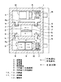
図1は、本発明の実施の形態1による気槽式熱衝撃試験装置の縦断面図である。図1において、筐体1は周囲が断熱材1aで形成され、その内部には、試験室2、低温槽3および高温槽4がそれぞれ設けられ、各々の境界は断熱材1aにより区切られている。試験室2には被試験品5が収納される。低温槽3は低温熱量を蓄熱するためのもので、試験室2の下側に配置されている。また高温槽4は高温熱量を蓄熱するためのもので、試験室3の上側に配置されている。低温槽3と試験室2は低温空気供給路1bと低温空気回収路1cで連通され、これら低温空気供給路1bおよび低温空気回収路1cの開口部には、低温・高温試験に対応して開閉する低温ダンパ6が取り付けられている。また、高温槽4と試験室2は高温空気供給路1dと高温空気回収路1eで連通され、これら高温空気供給路1dおよび高温空気回収路1eの開口部には、低温・高温試験に対応して開閉する高温ダンパ7が取り付けられている。
【0015】
低温槽3内には、冷却器8、冷却器9、加熱器10および送風機11が設置されている。冷却器8は筐体1の外に設置された二元冷凍装置(図示省略)の高温側冷凍サイクルに接続され、冷却器9は二元冷凍装置の低温側冷凍サイクルに接続されている。加熱器10は冷却器8,9を通過した低温空気を加熱して、該低温空気の温度調節を行う。送風機11は低温槽3内の低温空気を低温空気供給路1b介して試験室2へ供給したり、または低温槽3上部に設けられた低温空気循環路3aを介して低温槽3内で空気を循環させて、低温熱量の蓄熱を行う。
【0016】
高温槽4内には、蓄熱材12、加熱器13および送風機14が設置されている。蓄熱材12は高温熱量を蓄熱し、加熱器13は高温熱源であり、蓄熱材12で加熱された高温空気を更に加熱する。送風機14は高温槽4内の高温空気を高温空気供給路1d介して試験室2へ供給したり、または高温槽4下部に設けられた高温空気循環路4aを介して高温槽4内で空気を循環させて、高温熱量の蓄熱を行う。
【0017】
上記構成の気槽式熱衝撃試験装置において、低温槽3内の空気の流れは、装置運転開始時における低温槽3内の温度が所定の温度に到達するまでの準備運転、または高温試験中の待機運転時は、低温ダンパ6が閉じた状態で図の実線矢印で示すように低温空気循環路3aを通り低温槽3内を循環し、低温試験時は、低温ダンパ6が開いた状態で図の破線矢印で示すように、低温空気供給路1bを通り試験室2に低温熱量を供給し、低温空気回収路1cを通り再び低温槽3内に戻るという循環経路となる。高温槽4内も同様の空気の流れとなり、低温ダンパ6および高温ダンパ7の開閉により試験室2に低温熱量と高温熱量を交互に供給し、被試験品5に対し熱衝撃を付加する熱衝撃試験を実施する。
【0018】
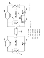
図2は、冷凍装置の冷凍サイクル系統の概略図である。気槽式熱衝撃試験装置では、低温槽内の温度をたとえば、−80℃にて蓄熱するため、冷凍装置として二元冷凍サイクルを採用している。この二元冷凍サイクルには、図2に示すように、低温側冷凍サイクルと高温側冷凍サイクルが設けられ、これらの低温側冷凍サイクルおよび高温側冷凍サイクルはカスケードコンデンサ20で接続されている。
【0019】
低温側冷凍サイクルの主要部品は、圧縮機21、膨張弁22、冷却器9およびカスケードコンデンサ20で構成されている。高温側冷凍サイクルの主要部品は、圧縮機23、凝縮器24、膨張弁25およびカスケードコンデンサ20で構成され、本実施の形態では更にカスケードコンデンサ20に並列に冷却器8が接続されている。また、冷媒に流れに沿ってカスケードコンデンサ20の上流側には電磁弁26が、冷却器8の上流側には電磁弁27がそれぞれ設けられている。
【0020】
そして、電磁弁26,27を開閉することにより、冷媒の流れを冷却器8側またはカスケードコンデンサ20側に切り替えることができる。すなわち、電磁弁26を閉に、電磁弁27を開とすれば冷媒を冷却器8側に、電磁弁26を開に、電磁弁27を閉とすれば冷媒をカスケードコンデンサ20側にそれぞれ流すことができる。なお、本実施の形態では、電磁弁26,27は切換手段を構成している。
【0021】
上記のように、電磁弁26,27の開閉により高温側冷凍サイクル内での冷媒流れの切り換えは、低温槽3内の温度により制御する。低温槽3内の温度が低い条件、たとえば、−40℃未満の場合には、従来方式と同様に二元冷凍方式の運転とするため、電磁弁27を閉に、電磁弁26を開として、冷媒をカスケードコンデンサ20側に流して、低温側冷凍サイクルの冷媒を冷却し液化する。このとき、高温側冷凍サイクルの冷却器8は、低温熱量を蓄えるための蓄冷材として利用することができる。
【0022】
次に、低温槽3内の温度が高い条件、たとえば−40℃以上の場合には、高温側冷凍サイクルのみの単段冷凍方式の運転とするため、電磁弁27を開に、電磁弁26を閉として、冷媒を冷却器8側に流して、冷媒の蒸発作用により低温熱量の蓄熱および試験室2への低温熱量の供給のための低温熱源となる。このとき、低温側冷凍サイクルの冷却器9は、低温熱量を蓄えるための蓄冷材として利用することができる。
【0023】
本実施の形態によれば、二元冷凍サイクルの運転を必要としない高温条件での運転の場合には、高温側冷凍サイクルの圧縮機のみを運転すれば良いこととなり、また、循環空気も冷却熱源となる冷媒の蒸発温度が二元冷凍サイクルに比べ高くなることから、過度に冷却されることがないため、設定温度に制御するための加熱器10の出力が抑制されることとなり、運転に要する消費電力を削減することが可能となる。また、各々の冷却器が、蓄冷材の役目も果たすため、低温熱量を蓄えるための蓄冷材を新たに設ける必要がない。
【0024】
(実施の形態2)
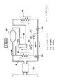
図3は本発明の実施の形態2を示しており、冷凍サイクル系統の概略図である。図3では高温側冷凍サイクルのみを示しており、低温側冷凍サイクルは図2の場合と同じである。実施の形態1と同様、カスケードコンデンサ20に並列に冷却器8が設けられている。そして、本実施の形態では、冷却器8をバイパスするバイパスライン30が設けられ、このバイパスライン30の途中に熱交換器31が設置されている。バイパスライン30の一端は冷却器8と電磁弁27との間のラインに接続され、他端は冷却器8の下流側のラインに接続されている。バイパスライン30には熱交換器31の上流側に電磁弁32が設けられている。また、熱交換器31には圧縮機23からの出口ラインが接続され、圧縮機23から凝縮器24間の冷媒との間で熱交換を行うことができる。なお、本実施の形態では、熱交換器31は加熱手段を構成している。
【0025】
上記構成において、低温槽3内の温度が低温条件たとえば−40℃未満の運転の場合には、電磁弁26を開に、電磁弁27を閉とし、冷媒をカスケードコンデンサ20側に流して二元冷凍方式の運転をする。そして、低温槽3内の温度が高温条件、たとえば−40℃以上の運転の場合には、電磁弁27を開に、電磁弁26を閉とし、冷媒を冷却器8側に流し高温側冷凍サイクルのみの単段冷凍方式の運転をする。さらに、本実施の形態では、低温槽3内の温度がたとえば−20℃以上の運転の場合には、バイパスライン30の電磁弁32を開にして、冷却器8に流れる冷媒量を減少させることで冷凍能力を抑制し、温度調整用の加熱器10の出力をさらに抑制することが可能となる。
【0026】
なお、バイパスライン30では、熱交換器31にて圧縮機23を出た高温の冷媒と熱交換することにより、バイパスライン30側の冷媒は、液の状態から過熱蒸気の状態となって冷却器8下流の出口ラインにて合流するため、冷凍サイクルの運転上の問題はない。したがって、上記により高温側冷凍サイクルのみの運転および冷凍能力の抑制による加熱器10の出力抑制によって消費電力を大幅に削減した運転が可能となる。
【0027】
また、バイパス回路に設けた電磁弁32を、冷媒の流量を比例的に調整できる流量調整弁に置き換えることにより、低温槽3内の温度に応じてバイパス流量を調整可能となり、その結果、広範囲にかつ効率的に加熱器10の出力を抑制することが可能となり、一層の省電力運転が可能となる。
【0028】
【発明の効果】
以上説明したように、本発明によれば、運転条件(低温槽内の温度)によって、二元冷凍方式による運転および高温側冷凍サイクルのみの単段冷凍方式による運転とに切り換えることにより、特に低温槽内の温度が高い条件の場合に、高温側冷凍サイクルの圧縮機のみを動かせば良く、また、高温側冷凍サイクルの運転であるため冷媒の蒸発温度が高く、循環空気の温度が必要以上に低下しないため、温度調整用の加熱器の出力を抑制することができる。その結果、熱衝撃試験に要する消費電力を低減することが可能となる。
【0029】
また、高温側冷凍サイクル用および低温側冷凍サイクル用の各々の冷却器が蓄冷材の役目も果たすため、蓄熱材が不要となり、コスト的にも有利である。
【図面の簡単な説明】
【図1】本発明の実施の形態1による気槽式熱衝撃試験装置の縦断面図である。
【図2】図1に示した気槽式熱衝撃試験装置の冷凍サイクル系統の概略図である。
【図3】本発明の実施の形態2による気槽式熱衝撃試験装置の冷凍サイクル系統の概略図である。
【符号の説明】
2 試験室
3 低温槽
4 高温槽
5 被試験品
6 低温ダンパ
7 高温ダンパ
8 冷却器(二元高温側)
9 冷却器(二元低温側)
10,13 加熱器
11,14 送風機
12 蓄熱材
20 カスケードコンデンサ
21,23 圧縮機
22,25 膨張弁
26,27,32 電磁弁
24 凝縮器
30 バイパスライン
31 熱交換器[0001]
BACKGROUND OF THE INVENTION
The present invention relates to a tank-type thermal shock test apparatus suitable for conducting a thermal shock test of electronic parts and the like, and an operation method thereof.
[0002]
[Prior art]
2. Description of the Related Art Conventionally, an air tank type thermal shock test apparatus has been used to evaluate changes in heat resistance, physical, and electrical characteristics of electronic components such as semiconductor devices in a short time. In the air tank type thermal shock test apparatus, for example, the temperature of the test chamber is changed rapidly and repeatedly from 0 ° C. to −65 ° C. on the low temperature side and from 60 ° C. to 200 ° C. on the high temperature side. Has been.
[0003]
As an air tank type thermal shock test apparatus for performing such a test, for example, one disclosed in Japanese Patent Laid-Open No. 5-187984 is known. In this air tank type thermal shock test apparatus, in order to rapidly change the temperature of the test chamber from high temperature to low temperature and from low temperature to high temperature, a low temperature bath and a high temperature bath are provided in addition to the test chamber. A high temperature heat amount is stored in advance, and the low temperature heat amount and the high temperature heat amount stored at the test temperature switching are radiated to realize a rapid temperature change. In the low-temperature tank, a cold storage material having a large heat capacity for storing the low-temperature heat quantity is provided separately from the cooler, and the refrigeration apparatus serving as the low-temperature heat source has a temperature in the low-temperature tank of, for example, 0 ° C. Since heat is stored at a temperature of −80 ° C., a dual refrigeration system is employed to obtain a minimum temperature of −80 ° C.
[0004]
[Problems to be solved by the invention]
By the way, when the low temperature side test temperature range is, for example, 0 ° C. to −65 ° C., in order to obtain a rapid temperature change, the temperature at which the low temperature heat is stored in the low temperature bath in advance is 0 ° C. to −80 ° C. The temperature is controlled by a refrigeration apparatus and a heater so as to reach any set temperature.
[0005]
However, in the above conventional technique, the cooler in the refrigeration apparatus is one system, and the cooler provided in the low temperature tank is connected to the low temperature side refrigeration cycle of the dual refrigeration cycle. In operation, the dual refrigeration cycle is operated. For this reason, it is necessary to operate the low temperature side and high temperature side two-line compressor even in operation at a temperature that does not require operation of the dual refrigeration cycle, for example, operation in which the temperature in the low temperature tank is controlled to -40 ° C or higher. In addition, there is a problem that the output of the heater for maintaining the temperature in the low temperature tank at the set temperature is increased to cool the circulating air more than necessary, resulting in an increase in power consumption required for the thermal shock test. .
[0006]
An object of the present invention is to provide an air tank type thermal shock test apparatus capable of reducing power consumption required for the thermal shock test and an operating method of the air tank type thermal shock test apparatus.
[0007]
[Means for Solving the Problems]
In order to achieve the above object, the present invention comprises a low-temperature tank that cools air to make it cold air, a high-temperature tank that heats air to make it hot air, and a test chamber in which the product to be tested is stored. In the air-bath-type thermal shock test apparatus for supplying thermal shock to the product under test by alternately supplying low-temperature air from the low-temperature tank and high-temperature air from the high-temperature tank to the test chamber, As a cooling cycle for cooling the air, a dual refrigeration cycle in which a high temperature side refrigeration cycle and a low temperature side refrigeration cycle are connected via a cascade condenser is provided, and two coolers are provided. Connected in parallel with the cascade capacitor in the cycle, the other cooler is connected in the low temperature side refrigeration cycle, and the refrigerant flow in the high temperature side refrigeration cycle is connected to the one cooler or Together with the switching means for switching to one of the cascade condenser provided to further install a bypass line for bypassing the one cooler, the refrigerant flowing through the bypass line, heated by the refrigerant from the compressor of the high-temperature side refrigerating cycle It is characterized by providing a heating means .
[0008]
According to the above configuration, in the operation by the single-stage refrigeration method using only the high temperature side refrigeration cycle, the refrigeration capacity is still excessive. For example, when the temperature in the low temperature tank is controlled to −20 ° C. or higher, a part of the refrigerant is used. The amount of refrigerant flowing to the cooler (one cooler) of the high temperature side refrigeration cycle is suppressed by flowing to the bypass line. In addition, after the refrigerant | coolant which flowed to the bypass line is heated with the refrigerant | coolant from a compressor, it merges in the downstream of a cooler .
[0009]
The bypass line can be provided with a flow rate adjusting valve. If the flow rate adjusting valve is provided in this way, the flow rate of the refrigerant flowing through the bypass line can be adjusted .
[0014]
DETAILED DESCRIPTION OF THE INVENTION
Hereinafter, embodiments of the present invention will be described with reference to the drawings.
(Embodiment 1)
FIG. 1 is a longitudinal sectional view of an air tank type thermal shock test apparatus according to Embodiment 1 of the present invention. In FIG. 1, the casing 1 is formed with a heat insulating material 1 a at the periphery, and a
[0015]
In the
[0016]
In the high-
[0017]
In the air tank type thermal shock test apparatus having the above-described configuration, the air flow in the
[0018]
FIG. 2 is a schematic diagram of a refrigeration cycle system of the refrigeration apparatus. In the air tank type thermal shock test apparatus, the temperature in the low temperature tank is stored at, for example, −80 ° C., and thus a dual refrigeration cycle is employed as the refrigeration apparatus. As shown in FIG. 2, the binary refrigeration cycle is provided with a low temperature side refrigeration cycle and a high temperature side refrigeration cycle, and the low temperature side refrigeration cycle and the high temperature side refrigeration cycle are connected by a
[0019]
The main components of the low temperature side refrigeration cycle include a
[0020]
Then, the flow of the refrigerant can be switched to the
[0021]
As described above, switching of the refrigerant flow in the high temperature side refrigeration cycle by opening and closing the
[0022]
Next, when the temperature in the low-
[0023]
According to the present embodiment, in the case of operation under a high temperature condition that does not require the operation of the dual refrigeration cycle, it is only necessary to operate the compressor of the high temperature side refrigeration cycle, and the circulating air is also cooled. Since the evaporating temperature of the refrigerant as the heat source is higher than that in the dual refrigeration cycle, it is not excessively cooled, so the output of the
[0024]
(Embodiment 2)
FIG. 3 shows a second embodiment of the present invention and is a schematic diagram of a refrigeration cycle system. FIG. 3 shows only the high temperature side refrigeration cycle, and the low temperature side refrigeration cycle is the same as in FIG. Similar to the first embodiment, a
[0025]
In the above configuration, when the temperature in the low-
[0026]
In the
[0027]
Further, by replacing the
[0028]
【The invention's effect】
As described above, according to the present invention, depending on the operating conditions (temperature in the low temperature tank), it is possible to switch between the operation by the dual refrigeration method and the operation by the single-stage refrigeration method only for the high temperature side refrigeration cycle. When the temperature in the tank is high, only the compressor of the high-temperature side refrigeration cycle needs to be moved. Since it does not decrease, the output of the temperature adjusting heater can be suppressed. As a result, it is possible to reduce the power consumption required for the thermal shock test.
[0029]
Further, each cooler for the high temperature side refrigeration cycle and the low temperature side refrigeration cycle also serves as a cold storage material, so that no heat storage material is required, which is advantageous in terms of cost.
[Brief description of the drawings]
FIG. 1 is a longitudinal sectional view of a gas tank type thermal shock test apparatus according to Embodiment 1 of the present invention.
2 is a schematic diagram of a refrigeration cycle system of the air tank type thermal shock test apparatus shown in FIG.
FIG. 3 is a schematic diagram of a refrigeration cycle system of an air tank type thermal shock test apparatus according to
[Explanation of symbols]
2
9 Cooler (Dual low temperature side)
10, 13
Claims (2)
前記低温槽で空気を冷却する冷却サイクルとして、高温側冷凍サイクルと低温側冷凍サイクルがカスケードコンデンサを介して接続された二元冷凍サイクルを設けるとともに、冷却器を二系統とし、一方の冷却器は前記高温側冷凍サイクルに前記カスケードコンデンサと並列に接続し、他方の冷却器は前記低温側冷凍サイクル内に接続し、かつ前記高温側冷凍サイクルにおける冷媒の流れを、前記一方の冷却器または前記カスケードコンデンサのいずれかに切り換える切換手段を設け、さらに前記一方の冷却器をバイパスするバイパスラインを設置するとともに、該バイパスラインを流れる冷媒を、前記高温側冷凍サイクルの圧縮機からの冷媒で加熱する加熱手段を設けたことを特徴とする気槽式熱衝撃試験装置。A low-temperature bath that cools the air to low-temperature air, a high-temperature bath that heats the air to high-temperature air, and a test chamber in which the product to be tested is stored. In the air tank type thermal shock test apparatus that alternately supplies high temperature air from the air and the high temperature tank to give a thermal shock to the device under test,
As a cooling cycle for cooling the air in the low-temperature tank, a dual refrigeration cycle in which a high-temperature refrigeration cycle and a low-temperature refrigeration cycle are connected via a cascade condenser is provided, and two coolers are provided. The high temperature side refrigeration cycle is connected in parallel with the cascade condenser, the other cooler is connected in the low temperature side refrigeration cycle, and the refrigerant flow in the high temperature side refrigeration cycle is changed to the one cooler or the cascade. Switching means for switching to any one of the condensers is provided, and further, a bypass line for bypassing the one cooler is installed, and the refrigerant flowing through the bypass line is heated by the refrigerant from the compressor of the high temperature side refrigeration cycle An air tank type thermal shock test apparatus characterized by comprising means.
前記バイパスラインに流量調整弁を設け、該バイパスラインに流れる冷媒の流量を調節可能としたことを特徴とする気槽式熱衝撃試験装置。In the air tank type thermal shock test device according to claim 1 ,
An air tank type thermal shock test apparatus characterized in that a flow rate adjusting valve is provided in the bypass line, and the flow rate of the refrigerant flowing through the bypass line can be adjusted.
Priority Applications (1)
| Application Number | Priority Date | Filing Date | Title |
|---|---|---|---|
| JP35526599A JP4088739B2 (en) | 1999-12-15 | 1999-12-15 | Air tank type thermal shock test equipment |
Applications Claiming Priority (1)
| Application Number | Priority Date | Filing Date | Title |
|---|---|---|---|
| JP35526599A JP4088739B2 (en) | 1999-12-15 | 1999-12-15 | Air tank type thermal shock test equipment |
Publications (2)
| Publication Number | Publication Date |
|---|---|
| JP2001174381A JP2001174381A (en) | 2001-06-29 |
| JP4088739B2 true JP4088739B2 (en) | 2008-05-21 |
Family
ID=18442934
Family Applications (1)
| Application Number | Title | Priority Date | Filing Date |
|---|---|---|---|
| JP35526599A Expired - Fee Related JP4088739B2 (en) | 1999-12-15 | 1999-12-15 | Air tank type thermal shock test equipment |
Country Status (1)
| Country | Link |
|---|---|
| JP (1) | JP4088739B2 (en) |
Cited By (1)
| Publication number | Priority date | Publication date | Assignee | Title |
|---|---|---|---|---|
| CN106492889A (en) * | 2016-11-25 | 2017-03-15 | 防城港市质量技术监督局 | A kind of caloric test case |
Families Citing this family (10)
| Publication number | Priority date | Publication date | Assignee | Title |
|---|---|---|---|---|
| JP4594240B2 (en) * | 2006-01-05 | 2010-12-08 | エスペック株式会社 | Thermal fatigue evaluation method and thermal fatigue evaluation apparatus |
| JP2008058017A (en) * | 2006-08-29 | 2008-03-13 | Shimadzu Corp | Metal thermal fatigue testing machine |
| CN110586206A (en) * | 2018-08-11 | 2019-12-20 | 广州威德玛环境仪器有限公司 | Miniature high low temperature test box |
| JP6650062B2 (en) * | 2019-02-20 | 2020-02-19 | エスペック株式会社 | Environmental test equipment |
| CN114629433A (en) * | 2020-12-10 | 2022-06-14 | 浙江爱旭太阳能科技有限公司 | Method for high-low temperature accelerated testing of solar photovoltaic module |
| CN115077910A (en) * | 2021-03-15 | 2022-09-20 | 中国航发商用航空发动机有限责任公司 | Aircraft engine accessory temperature test system and method |
| CN113049430A (en) * | 2021-03-30 | 2021-06-29 | 中国飞机强度研究所 | High-low temperature impact test device |
| CN113176136A (en) * | 2021-04-25 | 2021-07-27 | 宁波市信测检测技术有限公司 | Test device for simulating temperature shock environment |
| CN114674653B (en) * | 2022-03-29 | 2023-03-24 | 盐城市泽楷建设有限公司 | A concrete shrinkage test variable temperature chamber for building construction to improve the comprehensiveness of the test |
| CN116754273B (en) * | 2023-08-11 | 2023-11-14 | 合肥通用机械研究院有限公司 | Cold water unit reverse temperature working condition testing system and working condition unit control strategy |
-
1999
- 1999-12-15 JP JP35526599A patent/JP4088739B2/en not_active Expired - Fee Related
Cited By (1)
| Publication number | Priority date | Publication date | Assignee | Title |
|---|---|---|---|---|
| CN106492889A (en) * | 2016-11-25 | 2017-03-15 | 防城港市质量技术监督局 | A kind of caloric test case |
Also Published As
| Publication number | Publication date |
|---|---|
| JP2001174381A (en) | 2001-06-29 |
Similar Documents
| Publication | Publication Date | Title |
|---|---|---|
| KR101656583B1 (en) | Air conditioning system for a motor vehicle | |
| JP6537986B2 (en) | Temperature control system | |
| CN113492646B (en) | Thermal management device | |
| RU2706761C2 (en) | Vehicle | |
| JP4088739B2 (en) | Air tank type thermal shock test equipment | |
| JP7214227B2 (en) | temperature control system | |
| JP4211912B2 (en) | Constant temperature and humidity device | |
| JP6832939B2 (en) | Refrigeration cycle equipment | |
| JP2024061462A5 (en) | ||
| KR100884319B1 (en) | Chiller device for reducing power consumption | |
| KR20220156240A (en) | Automotive air conditioning system | |
| JP4503652B2 (en) | Automotive engine thermal energy control system with switching means with time delay | |
| CN113400887A (en) | Thermal management device | |
| CN101014814B (en) | cooling device | |
| JP4465860B2 (en) | Air conditioner refrigeration equipment | |
| JP3602341B2 (en) | Gas tank type thermal shock test apparatus and its operation method | |
| JPH0429752A (en) | Thermal shock test equipment | |
| CN117784854A (en) | Energy storage system temperature control equipment and method | |
| JP6650062B2 (en) | Environmental test equipment | |
| JP7650118B2 (en) | Cooling and heating equipment | |
| JPH0517580Y2 (en) | ||
| JP2006308278A (en) | Supercritical heat pump equipment | |
| JP6835116B2 (en) | Refrigeration equipment | |
| JPH07269983A (en) | Air conditioner for shop | |
| KR20260002001A (en) | Thermal management system for vehicle |
Legal Events
| Date | Code | Title | Description |
|---|---|---|---|
| A621 | Written request for application examination |
Free format text: JAPANESE INTERMEDIATE CODE: A621 Effective date: 20060517 |
|
| A977 | Report on retrieval |
Free format text: JAPANESE INTERMEDIATE CODE: A971007 Effective date: 20071012 |
|
| A131 | Notification of reasons for refusal |
Free format text: JAPANESE INTERMEDIATE CODE: A131 Effective date: 20071023 |
|
| A521 | Written amendment |
Free format text: JAPANESE INTERMEDIATE CODE: A523 Effective date: 20071225 |
|
| TRDD | Decision of grant or rejection written | ||
| A01 | Written decision to grant a patent or to grant a registration (utility model) |
Free format text: JAPANESE INTERMEDIATE CODE: A01 Effective date: 20080122 |
|
| A61 | First payment of annual fees (during grant procedure) |
Free format text: JAPANESE INTERMEDIATE CODE: A61 Effective date: 20080212 |
|
| R150 | Certificate of patent or registration of utility model |
Ref document number: 4088739 Country of ref document: JP Free format text: JAPANESE INTERMEDIATE CODE: R150 Free format text: JAPANESE INTERMEDIATE CODE: R150 |
|
| FPAY | Renewal fee payment (event date is renewal date of database) |
Free format text: PAYMENT UNTIL: 20110307 Year of fee payment: 3 |
|
| FPAY | Renewal fee payment (event date is renewal date of database) |
Free format text: PAYMENT UNTIL: 20110307 Year of fee payment: 3 |
|
| FPAY | Renewal fee payment (event date is renewal date of database) |
Free format text: PAYMENT UNTIL: 20120307 Year of fee payment: 4 |
|
| FPAY | Renewal fee payment (event date is renewal date of database) |
Free format text: PAYMENT UNTIL: 20130307 Year of fee payment: 5 |
|
| FPAY | Renewal fee payment (event date is renewal date of database) |
Free format text: PAYMENT UNTIL: 20130307 Year of fee payment: 5 |
|
| FPAY | Renewal fee payment (event date is renewal date of database) |
Free format text: PAYMENT UNTIL: 20140307 Year of fee payment: 6 |
|
| S111 | Request for change of ownership or part of ownership |
Free format text: JAPANESE INTERMEDIATE CODE: R313117 |
|
| S131 | Request for trust registration of transfer of right |
Free format text: JAPANESE INTERMEDIATE CODE: R313134 |
|
| S131 | Request for trust registration of transfer of right |
Free format text: JAPANESE INTERMEDIATE CODE: R313135 |
|
| R350 | Written notification of registration of transfer |
Free format text: JAPANESE INTERMEDIATE CODE: R350 |
|
| SZ03 | Written request for cancellation of trust registration |
Free format text: JAPANESE INTERMEDIATE CODE: R313Z03 |
|
| R350 | Written notification of registration of transfer |
Free format text: JAPANESE INTERMEDIATE CODE: R350 |
|
| R250 | Receipt of annual fees |
Free format text: JAPANESE INTERMEDIATE CODE: R250 |
|
| R250 | Receipt of annual fees |
Free format text: JAPANESE INTERMEDIATE CODE: R250 |
|
| R250 | Receipt of annual fees |
Free format text: JAPANESE INTERMEDIATE CODE: R250 |
|
| S111 | Request for change of ownership or part of ownership |
Free format text: JAPANESE INTERMEDIATE CODE: R313111 |
|
| LAPS | Cancellation because of no payment of annual fees | ||
| R350 | Written notification of registration of transfer |
Free format text: JAPANESE INTERMEDIATE CODE: R350 |