JP4088713B2 - Optical element, mounting method thereof, and optical module - Google Patents
Optical element, mounting method thereof, and optical module Download PDFInfo
- Publication number
- JP4088713B2 JP4088713B2 JP2001348253A JP2001348253A JP4088713B2 JP 4088713 B2 JP4088713 B2 JP 4088713B2 JP 2001348253 A JP2001348253 A JP 2001348253A JP 2001348253 A JP2001348253 A JP 2001348253A JP 4088713 B2 JP4088713 B2 JP 4088713B2
- Authority
- JP
- Japan
- Prior art keywords
- optical
- substrate
- optical element
- lens
- groove
- Prior art date
- Legal status (The legal status is an assumption and is not a legal conclusion. Google has not performed a legal analysis and makes no representation as to the accuracy of the status listed.)
- Expired - Fee Related
Links
- 230000003287 optical effect Effects 0.000 title claims description 141
- 238000000034 method Methods 0.000 title description 15
- 239000000758 substrate Substances 0.000 claims description 101
- 239000013307 optical fiber Substances 0.000 claims description 24
- 238000006243 chemical reaction Methods 0.000 claims description 18
- XUIMIQQOPSSXEZ-UHFFFAOYSA-N Silicon Chemical compound [Si] XUIMIQQOPSSXEZ-UHFFFAOYSA-N 0.000 claims description 8
- 239000013078 crystal Substances 0.000 claims description 8
- 229910052710 silicon Inorganic materials 0.000 claims description 8
- 239000010703 silicon Substances 0.000 claims description 8
- 230000004907 flux Effects 0.000 claims 1
- 239000011347 resin Substances 0.000 description 7
- 229920005989 resin Polymers 0.000 description 7
- 238000005530 etching Methods 0.000 description 6
- 230000002093 peripheral effect Effects 0.000 description 4
- 238000010586 diagram Methods 0.000 description 3
- 238000000206 photolithography Methods 0.000 description 3
- 239000004065 semiconductor Substances 0.000 description 3
- 230000015572 biosynthetic process Effects 0.000 description 2
- 238000004891 communication Methods 0.000 description 2
- 230000008878 coupling Effects 0.000 description 2
- 238000010168 coupling process Methods 0.000 description 2
- 238000005859 coupling reaction Methods 0.000 description 2
- 230000007423 decrease Effects 0.000 description 2
- 238000004519 manufacturing process Methods 0.000 description 2
- 239000003550 marker Substances 0.000 description 2
- 229910000679 solder Inorganic materials 0.000 description 2
- 229910001218 Gallium arsenide Inorganic materials 0.000 description 1
- -1 Inp Inorganic materials 0.000 description 1
- 230000000694 effects Effects 0.000 description 1
- 230000001747 exhibiting effect Effects 0.000 description 1
- 238000010438 heat treatment Methods 0.000 description 1
- 238000012986 modification Methods 0.000 description 1
- 230000004048 modification Effects 0.000 description 1
- 238000003825 pressing Methods 0.000 description 1
- 229920001187 thermosetting polymer Polymers 0.000 description 1
Images


Landscapes
- Mounting And Adjusting Of Optical Elements (AREA)
- Optical Couplings Of Light Guides (AREA)
- Diffracting Gratings Or Hologram Optical Elements (AREA)
Description
【0001】
【発明の属する技術分野】
本発明は,光通信機器に適用するのに好適な光学素子,該光学素子を含む光モジュール,および光学素子の実装方法に関するものである。
【0002】
【従来の技術】
光通信の分野において,レーザダイオードや光ファイバと結合されるマイクロレンズ等の光学素子が,例えば特開平7−199006号公報,特開平11−295561号公報に開示されている。前者では球状のボールレンズを用いて結合することが提案されている。後者では円形レンズの縁部に環状部分を設けたレンズが記載されている。
【0003】
また,上記分野のレンズ等の光学素子としてフォトリソ・エッチングプロセスを用いて製造されたものが考案されている。これは例えば,シリコン基板上にレンズ等の所望の形状をフォトリソグラフィ工程で形成した後,エッチングを行ってシリコンの不要な部分を除去して所望の光学素子を形成したものである。
【0004】
これらのレンズは,レーザダイオードや光ファイバ等が搭載される半導体支持基板上に形成された溝内に配置されることにより,相互の光軸を一致させて光学的に適正に結合されるように,位置決めされる。
【0005】
【発明が解決しようとする課題】
従来では,このようなレンズを実装する際,レンズが形成された面の上辺を基準にして位置決めを行い実装することが多い。しかしながら,この方法ではレンズの外形の形状によっては,実装誤差が生じることがある。特に,エッチング等により側面が形成されるレンズでは,この側面はレンズが形成された面に垂直な方向と若干の角度を有することがあり,この場合,レンズの傾きに伴い,距離の誤差が生じる。
【0006】
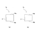
以下,図6,図7を参照しながらこの点について説明する。図6(a),(b)それぞれに側面から見た外形の平面的な形状が異なる2種類のレンズ素子1a,1bの側面方向の外形を表す図を示す。図6(a),(b)のレンズ素子1a,1bは共に紙面に垂直な左側の面の表面に形成されたレンズ部2を有する。レンズ部2が形成されている側の面をレンズ形成面と呼び,円形となっている。レンズ形成面と略垂直な面の形状はレンズ素子1aと1bで異なり,図に示すように上側の稜線と下側の稜線の違いとして現れている。
【0007】
図6(a)のレンズ素子1aは円柱状の形状であり,その一方の平坦面にレンズ部2が形成され,その外周面(側面)における上側の稜線14aと下側の稜線16aはレンズ形成面に対し垂直である。図6(b)のレンズ素子1bは円錐台の形状であり,その一方の平坦面にレンズ部2が形成され,その外周面(側面)における上側の稜線14bと下側の稜線16bはレンズ形成面に対し垂直ではなく,その直径はレンズ形成面からその対向面にいくに従い小さくなり,側面側から見た平面的な外形は台形形状をしている。
【0008】
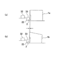
図7(a),(b)それぞれにレンズ素子1a,1bを,レンズ形成面の上辺を基準にして位置決めを行い,レーザダイオード等の光源32と結合するよう実装した場合の断面図を示す。図7(a),(b)において,レンズ素子1a,1bは支持基板上の溝部22に当接して載置されている。図7(a),(b)において,33はレーザダイオードの光軸を示す。
【0009】
レンズ素子1aの側面の稜線14aと稜線16aはレンズ形成面に対し垂直であるため,図7(a)に示すように所望の位置にレンズを配置できる。一方,レンズ素子1bの側面の稜線16bはレンズ形成面に対し垂直ではないため,稜線16bが溝部22に当接するよう載置すると,図7(b)に示すように,レンズ形成面が溝部22に対して垂直な面から傾く。この時に,レンズ形成面の上辺を基準にしてレンズを配置すると,図7(b)の矢印で示されるように,所望の位置に対して位置ずれが生じる。これは光軸方向の距離の誤差となる。このような光学系では,レンズの傾きよりもこの光軸方向の距離の誤差が大きな影響を及ぼし,レンズとレーザダイオードや光ファイバとの光結合の効率を低下させる深刻な原因となる。
【0010】
本発明の目的は,このような問題を解決し,高精度かつ容易に実装可能な光学素子,およびその実装方法,並びに高精度かつ容易に実装された光モジュールを提供することにある。
【0011】
【課題を解決するための手段】
上記課題を解決するために,本発明の第1の観点によれば,支持基板上に実装される光学素子であって,光学基板の表面に形成された光束変換部と,前記光束変換部の周辺の一部に沿った縁部と,前記光束変換部の周辺の他部側に前記光束変換部の表面に略平行な面内で前記光束変換部より広い幅を有するように延設された取扱部と,を具え,前記縁部と前記取扱部は,前記光学基板により構成されており,前記取扱部における前記光学基板の前記表面と前記光学基板の裏面とを繋ぐ前記光学基板の側面には,溝が設けられていることを特徴とする光学素子が提供される。
【0012】
ここで光束変換部とは光束を変換する機能を有するものであり,例えば光束を収束,発散,反射,偏向等するものである。また,光束変換部は,配置条件により入射光束を平行光に変換するものも含む。光束変換部の具体例としては,レンズや,回折光学素子からなる素子等が挙げられる。
【0013】
光学基板は結晶基板により構成してもよく,例えばシリコン結晶基板を用いることができる。また,その他の結晶基板としては,GaAs,Inp,GaP,SiC,Ge等を材料とする基板が挙げられる。
【0014】
かかる構成によれば,位置決め用の溝を用いて位置決めを行うことができるので,光学素子の外形の形状によらずに,高精度かつ容易に実装することができる。
【0015】
その際に,前記溝の断面形状は,略V字形状,略台形形状,略半円形状,略長方形形状,略正方形形状のいずれか1つであるように構成してもよい。
【0016】
前記溝は、前記光束変換部の光軸を含みかつ前記取扱部を横切る仮想平面に対して所定距離離れて設けられていることが好ましい。
【0017】
また,前記取扱部は略直方体形状を有し,前記縁部は円弧形状を有し,前記円弧形状が前記光学基板の前記表面側から前記光学基板の前記裏面側まで延びて蒲鉾形の張出部を形成しているように構成してもよい。このような構成を採用し,張出部の円弧の外形寸法を,この光学素子を支持基板上に実装する際にこの光学素子と結合される光ファイバの外径寸法と一致するようにすれば,実装時に好都合である。
また,前記溝は前記光学基板の前記表面と前記光学基板の裏面とに亘って設けられてもよい。
また,前記溝は前記光学基板の前記表面に対して垂直な方向に沿って設けられててもよい。
また,前記溝は,前記光学基板に複数設けられており、
また、前記複数の溝は,前記光束変換部の光軸を含みかつ前記取扱部を横切る仮想平面に対して非対称に設けられてもよい。かかる構成によれば,溝により光束変換部が形成されている面を容易に識別することができる。
【0018】
また,本発明の第2の観点によれば,上記に記載の光学素子を支持基板上に実装する光学素子の実装方法であって,前記支持基板上に位置決め用のマークを設け,前記光学素子の前記溝と前記支持基板上の前記マークとを用いて位置合わせを行い,前記光学素子を配置することを特徴とする光学素子の実装方法が提供される。
【0019】
かかる構成によれば,光学素子の溝と支持基板上のマークとを基準にして位置合わせを行うことにより,光学素子の外形の形状によらずに,高精度かつ容易に実装することができる。
【0020】
あるいは,上記に記載の光学素子を支持基板上に実装する光学素子の実装方法であって,前記支持基板上に位置決め用の凹部を設け,前記光学素子の前記溝と前記支持基板上の前記凹部とを用いて位置合わせを行い,前記光学素子を配置するようにしてもよい。凹部は凹溝により構成してもよい。
【0021】
かかる構成によれば,光学素子の溝と支持基板上の凹部とを基準にして位置合わせを行うことにより,光学素子の外形の形状によらずに,高精度かつ容易に実装することができる。
【0022】
また,本発明の第3の観点によれば,上記に記載の光学素子を用いた光モジュールであって,表面に溝部を有する支持基板と,前記支持基板上の前記溝部にその一部が配置された前記光学素子と,を具えることを特徴とする光モジュールが提供される。
【0023】
かかる構成によれば,光学素子の溝と支持基板上のマークとを用いて位置合わせを行って溝部に光学素子の一部を配置しているので,高精度に実装された光モジュールを提供できる。
また,前記支持基板の前記表面に,光源が配置されてもよい。
また,記支持基板の前記表面に,受光素子が配置されてもよい。
また,前記支持基板の前記表面には,位置合せマークが設けられてもよい。
また,前記支持基板の前記表面には,位置決め用の凹部が設けられてもよい。
また,前記支持基板上の前記溝部には,光ファイバが配置されてもよい。
【0024】
あるいは,上記に記載の光学素子を用いた光モジュールであって,表面に部材配置用の溝部と,位置決め用の凹部と,を有する支持基板と,前記光学素子の前記溝と前記支持基板上の前記凹部とを用いて位置合わせを行って前記支持基板上の前記溝部にその一部が配置された前記光学素子と,前記支持基板上の前記溝部に配置された光ファイバと,を具えるようにしてもよい。
【0025】
かかる構成によれば,光学素子の溝と支持基板上の凹部とを用いて位置合わせを行って溝部に光学素子を配置しているので,高精度に実装された光モジュールを提供できる。
【0026】
【発明の実施の形態】
以下,図面に基づいて本発明の実施の形態を詳細に説明する。なお,以下の説明および添付図面において,略同一の機能および構成を有する構成要素については,同一符号を付すことにより,重複説明を省略する。図1は,本発明の実施の形態にかかるレンズ素子1の構成を示す図であり,図1(a)は斜視図,図1(b)は下面図,図1(c)は側面方向から見た場合の平面的な外形を表す図である。レンズ素子1は,光学基板からなり,光学基板の片面に形成されたレンズ部2と,レンズ部2と接続された取扱部4を有する。
【0027】
レンズ部2はここでは円形形状をしており,回折光学素子からなる。レンズ部2は,回折光学素子の1つであるCGH(Computer Generated Hologram)素子により形成してもよい。CGH素子は,所望の光学特性を示す光学素子の光路差関数から所望の光学特性を得るに必要なフォトマスクのパターンをコンピュータを用いて求め,そのマスクパターンを用いて光学基板の表面の所望箇所にエッチング処理を施すことにより,所望の光学特性を有する回折型光学素子を形成したものである。
【0028】
取扱部4は,レンズ部2,縁部6,張出部9と一体的に形成されている。具体的には,取扱部4は,図1に示す通り,その両端間の中間部でレンズ部2の外周の上部側を取り巻くように延設され,レンズ部2表面に略平行な面内でレンズ部2よりも広い幅を有し,全体として略直方体状の形状を有する。以下,レンズ素子1において,レンズ部2が形成されている側の面をレンズ形成面と呼ぶ。すなわち,レンズ形成面は取扱部4の一面も含む。取扱部4の寸法としては,例えば,レンズ形成面における横方向の幅Wは500μm,レンズ形成面における縦方向の高さh1は100μm,レンズ形成面からその対向面にわたるレンズ形成面に対して垂直な方向の厚さtは100μmとできる。以下,幅W,高さh1,厚さt各々の方向に平行な方向をそれぞれ幅W方向,高さh方向,厚さt方向と呼ぶ。
【0029】
取扱部4の高さh方向に対して垂直な面である上面7は平坦に形成されている。上面7に対向する下側の面で,且つ張出部9の両側に位置する下面8は,レンズ素子1を支持基板に実装したとき,支持基板と近接する面となる。下面8には,図1(a),(b)に示すように,レンズ形成面およびレンズ形成面の対向面に開口部を有し,レンズ形成面側からその対向面側にわたり厚さt方向に伸長する3つの溝10a,10b,10cが形成されている。3つの溝10a,10b,10cのうちの少なくとも1つの溝はレンズ素子1を支持基板に実装する際の位置合わせのためのものである。溝10a,10b,10cの断面は略正方形形状をしている。レンズ部2の光軸を通り,幅W方向に垂直な面である仮想平面Pを考えたとき,溝10aと溝10cは仮想平面Pに対し反対側の位置に形成されている。溝10bは仮想平面Pを中心にしたとき溝10cと同じ側に形成されており,全体として溝10aと溝10b,10cとは仮想平面Pに対し非対称に配置されており,この構成によりレンズ形成面とその対向面を識別することができる。なお,溝10b,10cのいずれか一方と溝10aとが仮想平面Pに対して対称な位置に配置されていてもよい。
【0030】
縁部6はレンズ部2の下部側に位置し,レンズ部2の円周形状に沿った円弧形状を有する。この縁部6の円弧形状を呈する外形はレンズ形成面側からその対向面側まで延びており,レンズ部2の光軸を中心軸とする略円柱形状の一部である略蒲鉾形の形状となっている。取扱部4の中間位置から張り出す略蒲鉾形の部分を張出部9と呼ぶ。この張出部9の2つの端面は取扱部4の所定の対応する面とそれぞれ同一平面となる。そしてこの張出部9の一方の端面とそれに対応する取扱部4の所定の面とで成す平面にレンズ部2が形成されている。この張出部9の円弧の外径寸法は,レンズ素子1を半導体基板上に実装する際にレンズ素子1と結合される光ファイバの外径寸法と一致するようにすると実装時に好都合であり,縁部6の円弧の外径寸法を例えばφ125μmの光ファイバに適合するよう形成してもよい。
【0031】
取扱部4における幅W方向から見た側面を側面12とする。また、張出部9における幅W方向から見た側面を側面13とする。側面13の縦方向の高さ、すなわち高さh方向の幅を高さh2とする。言い換えれば,張出部9の頂点の下面8からの高さがh2となる。そして取扱部4の側面12の高さh1と張出部9の側面13の高さh2の合計を高さHとする。すなわち高さHは,幅W方向から見たレンズ素子1の高さh方向の幅である。高さHは一様ではなく,厚さt方向にわたりわずかに変化している。図1(c)は幅W方向から見たレンズ素子1の側面図である。稜線14は側面12の最上部における稜線である。稜線16は側面13の最下部における稜線である。図1(c)に示すように,稜線14と稜線16は,レンズ形成面に垂直な方向に対し若干の勾配を有し,高さHはレンズ形成面側からその対向面側にいくに従い減少し,レンズ素子1の幅W方向から見た外形の形状は略台形形状をしている。この高さHの変化量は微小なものであるが,図1(c)では理解を助けるために誇張して描いている。
【0032】
なお,上述の説明では,縁部6はレンズ部2を囲むように設けられているが,レンズ部2の外周が縁部6を構成するようになっていてもよい。レンズ素子1を形成する光学基板としては,結晶基板を用いることができる。特に,レンズ素子1を適用する光学系の光源の波長が1.3μmまたは1.5μmである場合には,シリコン結晶基板を用いることができる。
【0033】
レンズ素子1は,例えば半導体技術で用いられるフォトリソ・エッチング技術を用いて,シリコン基板にレンズ素子1に対応する形状のパターンをフォトマスクパターンとして用いてエッチングを行うことにより作製可能である。
【0034】
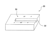
次に,本発明の第1の実施の形態にかかる,レンズ素子1を用いた光モジュールについて説明する。図2はこの光モジュールに用いられる支持基板の一例である。支持基板20は,その上面に溝部22と,位置合わせマーク24を有する。支持基板20は,例えばシリコン結晶基板からなる。溝部22は断面形状がV字状の溝である。
【0035】
位置合わせマーク24はレンズ素子1を実装する際に位置合わせに用いるものである。位置合わせマーク24は十字状のマークであり,溝部22の両側に4箇所ずつ,計8箇所に設けられている。この8箇所の位置合わせマーク24の位置は,レンズ素子1を支持基板20に実装した際にレンズ形成面とその対向面における溝10a,10cの開口部の位置と一致するように設けられている。
【0036】
図3に支持基板20とレンズ素子1とを用いた光モジュール30の一例を示す。光モジュール30は,支持基板20と,レーザダイオード等の光源32と,2つのレンズ素子1と,光ファイバ34とからなる。2つのレンズ素子1の張出部9と,光ファイバ34とは溝部22に配置されている。光源32と,2つのレンズ素子1と,光ファイバ34とは所定の間隔をもって配置され,光学的に結合している。光源32側のレンズ素子1のレンズ形成面は光源32側,光ファイバ34側のレンズ素子1のレンズ形成面は光ファイバ34側を向くように配置されている。図3(a)は光モジュール30の上面図であり,図3(b)は図3(a)のA−A’面における断面図である。図3(b)において,2つのレンズ素子1と,光ファイバ34とが接している溝部22の水平位置を点線で示している。
【0037】
次に光モジュール30を作製する際の実装方法について説明する。まず,レンズ素子1の取扱部4の上面7を吸着保持して,レンズ素子1をその張出部9が溝部22に当接する向きに,支持基板20上に載置する。この時,2つのレンズ素子1のレンズ形成面とその対向面における溝10a,10cの開口部と,支持基板20上の8箇所の位置合わせマーク24とを基準にして位置合わせを行い,CCDカメラ等による画像処理を利用して,2つのレンズ素子1を配置する。適切な位置にレンズ素子1が配置されたことを確認して各レンズ素子1を支持基板20に接合する。次に,光源32を支持基板20上部から例えばマーカーを用いて高精度に位置決めし,半田バンプ等で接合する。最後に光ファイバ34の周壁を溝部22の側壁に当接するように載置して樹脂等を用いて接合する。
【0038】
以上のように,本実施の形態では,レンズ素子1の取扱部4の下面8に形成された溝10a,10cと支持基板20上の位置合わせマーク24を用いて位置合わせを行う。これより,レンズ素子1の外形の形状によらず,短時間で容易に±1μmの高精度でレンズを実装することができる。さらに,溝を非対称に形成したことにより,実装前にレンズ部2側を容易に判別することができる。
【0039】
次に,本発明の第2の実施の形態にかかる,レンズ素子1を用いた光モジュールについて説明する。図4はこの光モジュールに用いられる支持基板の一例である。支持基板40は,その上面に溝部22と,溝部22に直交する2つの凹溝42a,42bを有する。支持基板40は,例えばシリコン結晶基板からなる。溝部22は断面形状がV字状の溝部である。
【0040】
凹溝42a,42bはレンズ素子1を実装する際に位置合わせに用いる溝であり,長方形状の断面形状を有し,例えばダイシングにより作製できる。本実施の形態では第1の実施の形態の位置合わせマーク24に代わり,凹溝42a,42bを用いて各レンズ素子1の位置合わせを行う。
【0041】
図5に支持基板40とレンズ素子1とを用いた光モジュール50の一例を示す。光モジュール50は,支持基板40と,レーザダイオード等の光源32と,2つのレンズ素子1と,光ファイバ34とからなる。2つのレンズ素子1と,光ファイバ34とは溝部22に配置されている。光源32と,2つのレンズ素子1と,光ファイバ34とは所定の間隔をもって配置され,光学的に結合している。光源32側のレンズ素子1のレンズ形成面は光源32側,光ファイバ34側のレンズ素子1のレンズ形成面は光ファイバ34側を向くように配置されている。図5(a)は光モジュール50の上面図であり,図5(b)は図5(a)のB−B’面における断面図である。図5(b)において,2つのレンズ素子1と,光ファイバ34とが接している溝部22の水平位置を点線で示している。
【0042】
次に光モジュール50を作製する際の実装方法について説明する。まず,レンズ素子1の取扱部4の上面7を吸着保持して,レンズ素子1をその張出部9が溝部22に当接する向きに,支持基板20上に載置する。この時,各々のレンズ素子1のレンズ形成面とその対向面における溝10a,10cの開口部の位置と,支持基板40上の凹溝42a,42bのエッジとを基準にして位置合わせを行い,CCDカメラ等による画像処理を利用して,レンズ素子1を配置する。適切な位置にレンズ素子1が配置されたことを確認したら,支持基板40上に熱硬化型の樹脂を均一に塗布し,上方より加圧し下方から加熱し樹脂を硬化させて,レンズ素子1と支持基板40を接合する。次に,光源32を支持基板40上部から例えばマーカーを用いて高精度に位置決めし,半田バンプ等で接合する。最後に光ファイバ34の周壁を溝部22の側壁に当接するように載置して樹脂等を用いて接合する。
【0043】
以上のように,本実施の形態では,レンズ素子1に形成された溝10a,10cと支持基板40上の凹溝42a,42bを用いて位置合わせを行う。これより,レンズ素子1の外形の形状によらず,短時間で容易に±1μmの高精度でレンズを実装することができる。また,溝を非対称に形成したことにより,実装前にレンズ部2側を容易に判別することができる。さらに,第1の実施の形態では,樹脂を用いて接合を行うと位置合わせマーク24が樹脂により覆われ,その位置が不明確となるが,本実施の形態では,位置合わせマーク24を用いずに凹溝42a,42bを用いて位置合わせを行っているため,樹脂を塗布しても位置合わせ基準となるものが不明確になることはない。なお,本実施の形態の光モジュールにおいては,光源32を用いているが,これに代えて,フォトダイオード等の受光素子を用いることもできる。
【0044】
以上,添付図面を参照しながら本発明にかかる好適な実施形態について説明したが,本発明はかかる例に限定されないことは言うまでもない。当業者であれば,特許請求の範囲に記載された技術的思想の範疇内において,各種の変更例または修正例に想到し得ることは明らかであり,それらについても当然に本発明の技術的範囲に属するものと了解される。
【0045】
上記例では,光学素子1の側面側から見た場合の外形が略台形形状のものについて説明したが,本発明はこれに限定するものではない。高さHがレンズ形成面側からその対向面側にわたり一定のものや,あるいはレンズ素子1の幅W方向から見た外形の形状が台形以外の形状のものについても本発明は適用可能である。
【0046】
レンズ部,縁部,取扱部,張出部,溝,溝部,位置合わせマーク,凹部,凹溝等の形状は上記例に限定されず,様々な形状が考えられる。例えば,レンズ部は,円形に限らず所望の形状で形成可能であり,また,屈折型のレンズ部としてもよい。溝,溝部,凹溝の断面形状は,上記の略正方形形状に限らず,略V字形状,略台形形状,略半円形状,略長方形形状,あるいは別の形状であってもよい。また,上記例では,光束変換部をレンズ部,また光学素子の例としてレンズ素子を例にとり説明したが,これに限定するものではない。例えば,光束変換部を光偏向部等とし,光学素子を光偏向素子等とした場合にも本発明は適用可能である。
【0047】
【発明の効果】
以上,詳細に説明したように本発明によれば,光学素子の外形の形状にかかわらず,高精度かつ容易に実装可能な光学素子,実装方法,および高精度かつ容易に実装された光モジュールを提供することができる。
【図面の簡単な説明】
【図1】 本発明の実施の形態に係るレンズ素子の構成を示し,図1(a)は斜視図,図1(b)は下面図,図1(c)は側面図である。
【図2】 本発明の第1の実施の形態に係る支持基板の構成を示す斜視図である。
【図3】 本発明の第1の実施の形態に係る光モジュールの構成を示し,図3(a)は上面図,図3(b)は図3(a)のA−A’面における断面図である。
【図4】 本発明の第2の実施の形態に係る支持基板の構成を示す斜視図である。
【図5】 本発明の第2の実施の形態に係る光モジュールの構成を示し,図5(a)は上面図,図5(b)は図5(a)のB−B’面における断面図である。
【図6】 レンズ素子の側面方向の外形を表す図である。
【図7】 図6に示すレンズ素子を実装した場合の断面図である。
【符号の説明】
1,1a,1b レンズ素子
2 レンズ部
4 取扱部
6 縁部
7 上面
8 下面
9 張出部
10a,10b,10c 溝
12,13 側面
14,14a,14b,16,16a,16b 稜線
20,40 支持基板
22 溝部
24 位置合わせマーク
30,50 光モジュール
32 光源
33 光軸
34 光ファイバ
42a,42b 凹溝[0001]
BACKGROUND OF THE INVENTION
The present invention relates to an optical element suitable for application to an optical communication device, an optical module including the optical element, and an optical element mounting method.
[0002]
[Prior art]
In the field of optical communication, optical elements such as a microlens coupled to a laser diode or an optical fiber are disclosed in, for example, Japanese Patent Application Laid-Open Nos. 7-199006 and 11-295561. In the former, it is proposed to use a spherical ball lens for coupling. The latter describes a lens in which an annular portion is provided at the edge of a circular lens.
[0003]
In addition, an optical element such as a lens in the above-mentioned field manufactured using a photolithography / etching process has been devised. For example, a desired shape such as a lens is formed on a silicon substrate by a photolithography process, and then etching is performed to remove unnecessary portions of silicon to form a desired optical element.
[0004]
These lenses are placed in a groove formed on a semiconductor support substrate on which a laser diode, an optical fiber, etc. are mounted so that their optical axes coincide with each other so as to be optically coupled appropriately. , Positioned.
[0005]
[Problems to be solved by the invention]
Conventionally, when mounting such a lens, positioning is often performed with reference to the upper side of the surface on which the lens is formed. However, this method may cause a mounting error depending on the outer shape of the lens. In particular, in a lens having a side surface formed by etching or the like, this side surface may have a slight angle with the direction perpendicular to the surface on which the lens is formed. In this case, an error in distance occurs due to the tilt of the lens. .
[0006]
Hereinafter, this point will be described with reference to FIGS. FIGS. 6 (a) and 6 (b) are diagrams showing the outer shape in the side surface direction of two types of
[0007]
The
[0008]
FIGS. 7A and 7B are cross-sectional views when the
[0009]
Since the
[0010]
An object of the present invention is to solve such problems, and provide an optical element that can be mounted with high accuracy and easily, a mounting method thereof, and an optical module that is mounted with high accuracy and ease.
[0011]
[Means for Solving the Problems]
In order to solve the above problems, according to a first aspect of the present invention, there is provided an optical element mounted on a support substrate, the light beam conversion unit formed on the surface of the optical substrate, and the light beam conversion unit. An edge part along a part of the periphery and the other part of the periphery of the light beam conversion part are extended so as to have a wider width than the light beam conversion part in a plane substantially parallel to the surface of the light beam conversion part. A handling part, wherein the edge part and the handling part are constituted by the optical substrate, and are arranged on a side surface of the optical substrate connecting the front surface of the optical substrate and the back surface of the optical substrate in the handling unit. Provides an optical element characterized in that a groove is provided .
[0012]
Here, the light beam conversion unit has a function of converting a light beam, and for example, converges, diverges, reflects, or deflects the light beam. Further, the light beam conversion unit includes a unit that converts an incident light beam into parallel light according to the arrangement condition. Specific examples of the light beam conversion unit include a lens and an element made of a diffractive optical element.
[0013]
The optical substrate may be composed of a crystal substrate, for example, a silicon crystal substrate can be used. Other crystal substrates include substrates made of GaAs, Inp, GaP, SiC, Ge, or the like.
[0014]
According to such a configuration, since positioning can be performed using the positioning groove, mounting can be performed with high accuracy and easily regardless of the outer shape of the optical element.
[0015]
At this time, the cross-sectional shape of the groove may be any one of a substantially V shape, a substantially trapezoidal shape, a substantially semicircular shape, a substantially rectangular shape, and a substantially square shape.
[0016]
It is preferable that the groove is provided at a predetermined distance from a virtual plane that includes the optical axis of the light beam conversion unit and crosses the handling unit.
[0017]
The handling portion has a substantially rectangular parallelepiped shape, the edge portion has an arc shape, and the arc shape extends from the front surface side of the optical substrate to the back surface side of the optical substrate to form a bowl-shaped protrusion. You may comprise so that the part may be formed. By adopting such a configuration, if the outer dimension of the arc of the overhanging part matches the outer diameter of the optical fiber coupled with the optical element when the optical element is mounted on the support substrate, , Convenient for implementation.
The groove may be provided across the front surface of the optical substrate and the back surface of the optical substrate.
The groove may be provided along a direction perpendicular to the surface of the optical substrate.
In addition, a plurality of the grooves are provided in the optical substrate,
The plurality of grooves may be provided asymmetrically with respect to a virtual plane that includes the optical axis of the light beam conversion unit and crosses the handling unit. According to such a configuration, it is possible to easily identify the surface on which the light beam conversion portion is formed by the groove.
[0018]
According to a second aspect of the present invention, there is provided an optical element mounting method for mounting the above-described optical element on a support substrate, wherein a positioning mark is provided on the support substrate, and the optical element An optical element mounting method is provided, wherein alignment is performed using the groove and the mark on the support substrate, and the optical element is disposed.
[0019]
According to such a configuration, by performing alignment based on the groove of the optical element and the mark on the support substrate, it is possible to mount with high accuracy and easily regardless of the outer shape of the optical element.
[0020]
Alternatively, an optical element mounting method for mounting the optical element described above on a support substrate, wherein a positioning recess is provided on the support substrate, and the groove of the optical element and the recess on the support substrate are provided. The optical elements may be arranged by aligning the positions of the optical elements. The recess may be constituted by a groove.
[0021]
According to such a configuration, by performing alignment based on the groove of the optical element and the concave portion on the support substrate, it is possible to mount with high accuracy and easily regardless of the outer shape of the optical element.
[0022]
According to a third aspect of the present invention, there is provided an optical module using the above-described optical element, wherein a support substrate having a groove portion on a surface thereof, and a part thereof being disposed in the groove portion on the support substrate. An optical module comprising the above-described optical element is provided.
[0023]
According to such a configuration, alignment is performed using the groove of the optical element and the mark on the support substrate, and a part of the optical element is arranged in the groove, so that an optical module mounted with high accuracy can be provided. .
A light source may be disposed on the surface of the support substrate.
A light receiving element may be disposed on the surface of the support substrate.
An alignment mark may be provided on the surface of the support substrate.
In addition, a positioning recess may be provided on the surface of the support substrate.
An optical fiber may be disposed in the groove on the support substrate.
[0024]
Or it is an optical module using the above-mentioned optical element, Comprising: The support substrate which has the groove part for member arrangement | positioning on the surface, and the recessed part for positioning, The said groove | channel of the said optical element, and the said support substrate The optical element disposed in the groove portion on the support substrate and aligned with the concave portion and the optical fiber disposed in the groove portion on the support substrate are provided. It may be.
[0025]
According to this configuration, since the optical element is arranged in the groove portion by performing alignment using the groove of the optical element and the concave portion on the support substrate, an optical module mounted with high accuracy can be provided.
[0026]
DETAILED DESCRIPTION OF THE INVENTION
Hereinafter, embodiments of the present invention will be described in detail with reference to the drawings. In the following description and the accompanying drawings, components having substantially the same function and configuration are denoted by the same reference numerals, and redundant description is omitted. FIG. 1 is a diagram showing a configuration of a
[0027]
Here, the
[0028]
The handling part 4 is formed integrally with the
[0029]
The
[0030]
The
[0031]
Let the side surface seen from the width W direction in the handling part 4 be the
[0032]
In the above description, the
[0033]
The
[0034]
Next, an optical module using the
[0035]
The
[0036]
FIG. 3 shows an example of an
[0037]
Next, a mounting method when manufacturing the
[0038]
As described above, in the present embodiment, alignment is performed using the
[0039]
Next, an optical module using the
[0040]
The
[0041]
FIG. 5 shows an example of an
[0042]
Next, a mounting method for manufacturing the
[0043]
As described above, in the present embodiment, alignment is performed using the
[0044]
As mentioned above, although preferred embodiment concerning this invention was described referring an accompanying drawing, it cannot be overemphasized that this invention is not limited to this example. It is obvious for those skilled in the art that various changes or modifications can be conceived within the scope of the technical idea described in the claims. It is understood that it belongs to.
[0045]
In the above example, the outer shape when viewed from the side of the
[0046]
The shape of the lens portion, the edge portion, the handling portion, the overhang portion, the groove, the groove portion, the alignment mark, the concave portion, the concave groove, etc. is not limited to the above example, and various shapes are conceivable. For example, the lens portion is not limited to a circular shape and can be formed in a desired shape, and may be a refractive lens portion. The cross-sectional shapes of the grooves, groove portions, and concave grooves are not limited to the substantially square shape described above, but may be a substantially V shape, a substantially trapezoidal shape, a substantially semicircular shape, a substantially rectangular shape, or another shape. In the above example, the light beam conversion unit is described as a lens unit, and the lens element is described as an example of an optical element. However, the present invention is not limited to this. For example, the present invention can be applied to a case where the light beam conversion unit is a light deflection unit or the like and the optical element is a light deflection element or the like.
[0047]
【The invention's effect】
As described above in detail, according to the present invention, an optical element that can be mounted with high accuracy and easily regardless of the outer shape of the optical element, a mounting method, and an optical module that is mounted with high accuracy and ease are provided. Can be provided.
[Brief description of the drawings]
1A and 1B show a configuration of a lens element according to an embodiment of the present invention, in which FIG. 1A is a perspective view, FIG. 1B is a bottom view, and FIG. 1C is a side view.
FIG. 2 is a perspective view showing a configuration of a support substrate according to the first embodiment of the present invention.
3 shows the configuration of the optical module according to the first embodiment of the present invention, FIG. 3 (a) is a top view, and FIG. 3 (b) is a cross section taken along the plane AA ′ of FIG. 3 (a). FIG.
FIG. 4 is a perspective view showing a configuration of a support substrate according to a second embodiment of the present invention.
FIGS. 5A and 5B show a configuration of an optical module according to a second embodiment of the present invention, in which FIG. 5A is a top view and FIG. 5B is a cross section taken along the line BB ′ in FIG. FIG.
FIG. 6 is a diagram illustrating an outer shape of a lens element in a side surface direction.
7 is a cross-sectional view when the lens element shown in FIG. 6 is mounted.
[Explanation of symbols]
1, 1a,
Claims (16)
光学基板の表面に形成された光束変換部と,
前記光束変換部の周辺の一部に沿った縁部と,
前記光束変換部の周辺の他部側に前記光束変換部の表面に略平行な面内で前記光束変換部より広い幅を有するように延設された取扱部と,
を具え,
前記縁部と前記取扱部は,前記光学基板により構成されており,
前記取扱部における前記光学基板の前記表面と前記光学基板の裏面とを繋ぐ前記光学基板の側面には,溝が設けられていることを特徴とする光学素子。An optical element mounted on a support substrate,
A light flux converter formed on the surface of the optical substrate;
An edge along a part of the periphery of the light beam conversion unit;
A handling portion extended on the other side of the periphery of the light beam converting portion so as to have a width wider than the light beam converting portion in a plane substantially parallel to the surface of the light beam converting portion;
With
The edge part and the handling part are constituted by the optical substrate,
An optical element , wherein a groove is provided on a side surface of the optical substrate that connects the front surface of the optical substrate and the back surface of the optical substrate in the handling unit.
前記複数の溝は,前記光束変換部の光軸を含みかつ前記取扱部を横切る仮想平面に対して非対称に設けられていることを特徴とする請求項1から9のいずれか1項に記載の光学素子。 The said some groove | channel is provided asymmetrically with respect to the virtual plane which contains the optical axis of the said light beam conversion part, and crosses the said handling part. Optical element.
表面に溝部を有する支持基板と,
前記支持基板上の前記溝部にその一部が配置された前記光学素子と,
を具えることを特徴とする光モジュール。An optical module using the optical element according to any one of claims 1 to 10 ,
A support substrate having a groove on the surface;
A portion of the optical element disposed in the groove on the support substrate;
An optical module comprising:
Priority Applications (8)
| Application Number | Priority Date | Filing Date | Title |
|---|---|---|---|
| JP2001348253A JP4088713B2 (en) | 2001-11-14 | 2001-11-14 | Optical element, mounting method thereof, and optical module |
| EP06112502A EP1686399A1 (en) | 2001-05-02 | 2002-05-02 | Method for manufacturing optical member |
| EP02009881A EP1256830B1 (en) | 2001-05-02 | 2002-05-02 | Optical member with handling portion and method for manufacturing optical member and method for mounting optical member and optical module |
| DE60213317T DE60213317T2 (en) | 2001-05-02 | 2002-05-02 | Optical component with handling device, method for its production and attachment as well as optical module |
| US10/136,326 US6683733B2 (en) | 2001-05-02 | 2002-05-02 | Optical member with handling portion and method for manufacturing optical member and method for mounting optical member and optical module |
| US10/724,625 US6798589B2 (en) | 2001-05-02 | 2003-12-02 | Optical member with handling portion and method for manufacturing optical member and method for mounting optical member and optical module |
| US10/854,339 US7016127B2 (en) | 2001-05-02 | 2004-05-27 | Optical member with handling portion and method for manufacturing optical member and method for mounting optical member and optical module |
| US11/227,088 US7102835B2 (en) | 2001-05-02 | 2005-09-16 | Optical member with handling portion and method for manufacturing optical member and method for mounting optical member and optical module |
Applications Claiming Priority (1)
| Application Number | Priority Date | Filing Date | Title |
|---|---|---|---|
| JP2001348253A JP4088713B2 (en) | 2001-11-14 | 2001-11-14 | Optical element, mounting method thereof, and optical module |
Related Child Applications (1)
| Application Number | Title | Priority Date | Filing Date |
|---|---|---|---|
| JP2007325295A Division JP4575421B2 (en) | 2007-12-17 | 2007-12-17 | Mounting method of optical element |
Publications (2)
| Publication Number | Publication Date |
|---|---|
| JP2003149519A JP2003149519A (en) | 2003-05-21 |
| JP4088713B2 true JP4088713B2 (en) | 2008-05-21 |
Family
ID=19161110
Family Applications (1)
| Application Number | Title | Priority Date | Filing Date |
|---|---|---|---|
| JP2001348253A Expired - Fee Related JP4088713B2 (en) | 2001-05-02 | 2001-11-14 | Optical element, mounting method thereof, and optical module |
Country Status (1)
| Country | Link |
|---|---|
| JP (1) | JP4088713B2 (en) |
Cited By (1)
| Publication number | Priority date | Publication date | Assignee | Title |
|---|---|---|---|---|
| JPH0730859U (en) * | 1993-12-01 | 1995-06-13 | イタルトービジャパン株式会社 | Sucker hook |
-
2001
- 2001-11-14 JP JP2001348253A patent/JP4088713B2/en not_active Expired - Fee Related
Cited By (1)
| Publication number | Priority date | Publication date | Assignee | Title |
|---|---|---|---|---|
| JPH0730859U (en) * | 1993-12-01 | 1995-06-13 | イタルトービジャパン株式会社 | Sucker hook |
Also Published As
| Publication number | Publication date |
|---|---|
| JP2003149519A (en) | 2003-05-21 |
Similar Documents
| Publication | Publication Date | Title |
|---|---|---|
| US7137745B2 (en) | Subassembly and optical module | |
| JP2001174671A (en) | Optical element module | |
| JP3974480B2 (en) | Optical member mounting method and optical module | |
| JP3889247B2 (en) | Optical module and method for assembling the same | |
| JP4008649B2 (en) | Optical device | |
| JP3974459B2 (en) | Optical element, mounting method thereof, and optical module | |
| US20060078262A1 (en) | Optoelectronic module with high coupling efficiency | |
| EP2798389A1 (en) | Integrated circuit coupling system with waveguide circuitry and method of manufacture thereof | |
| US20150331212A1 (en) | Method for forming optoelectronic modules connectable to optical fibers and optoelectronic module connectable to at least one optical fiber | |
| JPH10282364A (en) | Assembly of optical device | |
| JP3909500B2 (en) | Optical element and optical element manufacturing method | |
| JP2005532592A (en) | True position bench | |
| JP4240890B2 (en) | Optical element manufacturing method and optical element | |
| US7263249B2 (en) | Optical element assembly and method of making the same | |
| JP4088713B2 (en) | Optical element, mounting method thereof, and optical module | |
| JP3696802B2 (en) | Micro lens and optical module | |
| WO2020235041A1 (en) | Waveguide connection structure, waveguide chip, connector, method for manufacturing waveguide connection component, and method for connecting wavegude | |
| JP4575421B2 (en) | Mounting method of optical element | |
| CN105229508A (en) | For the formation of can be connected to optical fiber optical-electric module method and the optical-electric module of at least one optical fiber can be connected to | |
| US20110164848A1 (en) | Ball Lens Holder For A Planar Lightwave Circuit Device | |
| JP3761051B2 (en) | Manufacturing method of optical semiconductor coupling device | |
| JP2000275480A (en) | Optical module | |
| JP4202717B2 (en) | Beam shaping element and optical device | |
| JP2005010334A (en) | Composite optical element, composite optical component, and method of manufacturing composite optical element | |
| JP3909002B2 (en) | Optical module |
Legal Events
| Date | Code | Title | Description |
|---|---|---|---|
| A621 | Written request for application examination |
Free format text: JAPANESE INTERMEDIATE CODE: A621 Effective date: 20040916 |
|
| A977 | Report on retrieval |
Free format text: JAPANESE INTERMEDIATE CODE: A971007 Effective date: 20060426 |
|
| A131 | Notification of reasons for refusal |
Free format text: JAPANESE INTERMEDIATE CODE: A131 Effective date: 20071016 |
|
| A521 | Written amendment |
Free format text: JAPANESE INTERMEDIATE CODE: A523 Effective date: 20071217 |
|
| TRDD | Decision of grant or rejection written | ||
| A01 | Written decision to grant a patent or to grant a registration (utility model) |
Free format text: JAPANESE INTERMEDIATE CODE: A01 Effective date: 20080129 |
|
| A61 | First payment of annual fees (during grant procedure) |
Free format text: JAPANESE INTERMEDIATE CODE: A61 Effective date: 20080130 |
|
| A61 | First payment of annual fees (during grant procedure) |
Free format text: JAPANESE INTERMEDIATE CODE: A61 Effective date: 20080211 |
|
| R150 | Certificate of patent or registration of utility model |
Free format text: JAPANESE INTERMEDIATE CODE: R150 |
|
| FPAY | Renewal fee payment (event date is renewal date of database) |
Free format text: PAYMENT UNTIL: 20110307 Year of fee payment: 3 |
|
| FPAY | Renewal fee payment (event date is renewal date of database) |
Free format text: PAYMENT UNTIL: 20110307 Year of fee payment: 3 |
|
| FPAY | Renewal fee payment (event date is renewal date of database) |
Free format text: PAYMENT UNTIL: 20110307 Year of fee payment: 3 |
|
| FPAY | Renewal fee payment (event date is renewal date of database) |
Free format text: PAYMENT UNTIL: 20110307 Year of fee payment: 3 |
|
| FPAY | Renewal fee payment (event date is renewal date of database) |
Free format text: PAYMENT UNTIL: 20110307 Year of fee payment: 3 |
|
| S111 | Request for change of ownership or part of ownership |
Free format text: JAPANESE INTERMEDIATE CODE: R313111 |
|
| S531 | Written request for registration of change of domicile |
Free format text: JAPANESE INTERMEDIATE CODE: R313531 |
|
| FPAY | Renewal fee payment (event date is renewal date of database) |
Free format text: PAYMENT UNTIL: 20110307 Year of fee payment: 3 |
|
| R350 | Written notification of registration of transfer |
Free format text: JAPANESE INTERMEDIATE CODE: R350 |
|
| FPAY | Renewal fee payment (event date is renewal date of database) |
Free format text: PAYMENT UNTIL: 20110307 Year of fee payment: 3 |
|
| FPAY | Renewal fee payment (event date is renewal date of database) |
Free format text: PAYMENT UNTIL: 20120307 Year of fee payment: 4 |
|
| FPAY | Renewal fee payment (event date is renewal date of database) |
Free format text: PAYMENT UNTIL: 20120307 Year of fee payment: 4 |
|
| FPAY | Renewal fee payment (event date is renewal date of database) |
Free format text: PAYMENT UNTIL: 20130307 Year of fee payment: 5 |
|
| FPAY | Renewal fee payment (event date is renewal date of database) |
Free format text: PAYMENT UNTIL: 20140307 Year of fee payment: 6 |
|
| S531 | Written request for registration of change of domicile |
Free format text: JAPANESE INTERMEDIATE CODE: R313531 |
|
| S533 | Written request for registration of change of name |
Free format text: JAPANESE INTERMEDIATE CODE: R313533 |
|
| R350 | Written notification of registration of transfer |
Free format text: JAPANESE INTERMEDIATE CODE: R350 |
|
| LAPS | Cancellation because of no payment of annual fees |