JP4086850B2 - Door opening position adjustment system - Google Patents
Door opening position adjustment system Download PDFInfo
- Publication number
- JP4086850B2 JP4086850B2 JP2005032971A JP2005032971A JP4086850B2 JP 4086850 B2 JP4086850 B2 JP 4086850B2 JP 2005032971 A JP2005032971 A JP 2005032971A JP 2005032971 A JP2005032971 A JP 2005032971A JP 4086850 B2 JP4086850 B2 JP 4086850B2
- Authority
- JP
- Japan
- Prior art keywords
- sliding door
- guide
- pin
- rotation
- door panel
- Prior art date
- Legal status (The legal status is an assumption and is not a legal conclusion. Google has not performed a legal analysis and makes no representation as to the accuracy of the status listed.)
- Expired - Fee Related
Links
Images


Landscapes
- Hinges (AREA)
Description
本発明は、扉を開けると戸枠内に形成される開口部の位置を、開口部の使用態様など必要に応じて調整することのできる扉開口位置調整システムに関する。 The present invention relates to a door opening position adjustment system capable of adjusting the position of an opening formed in a door frame when the door is opened, as required, such as a use mode of the opening.
一般に、開き戸や引戸など、扉を付設した開閉式の開口部は、そこを出入する通行事情によっては、扉を開けたときに、そこが大きく開口していることが必要な場合がある。そこで、従来では、このような開口部には、例えば大型な開き戸を設置し、この開き戸を開けたときに大きな開口が形成されるようにしている。また、開口部の通行事情に応じて、大きな開口が扉の片側にのみ形成される必要が場合には、開口部に大型な観音扉式の開き戸を設置したり、複数の引戸を重ねて設置したりし、必要に応じて片開き状態にして対応している。 In general, an opening / closing type opening provided with a door, such as a hinged door or a sliding door, may require a large opening when the door is opened depending on traffic conditions for entering and exiting the door. Therefore, conventionally, for example, a large hinged door is installed in such an opening, and when the hinged door is opened, a large opening is formed. Also, if a large opening needs to be formed only on one side of the door, depending on the traffic situation of the opening, install a large double-door door or install multiple sliding doors on top of each other If necessary, it can be opened as needed.
ところが、上述した従来の開き戸式の扉では、扉が大型であるため、場合によっては、その重量で蝶番などのヒンジ部が損壊したりするおそれがある。また、大型な分だけ広い開閉可動スペースを、余分に扉周りに確保する必要があるという問題もある。一方、複数の引戸を重ねて設置する方式では、そもそも壁体と引戸パネル相互間に段差を発生し、この段差が目立って、美観上見栄えが悪いという課題があった。 However, in the above-described conventional hinged door type door, since the door is large, the hinge portion such as a hinge may be damaged by the weight in some cases. In addition, there is also a problem that it is necessary to secure an extra opening and closing movable space around the door as large as possible. On the other hand, in the system in which a plurality of sliding doors are stacked, a step is generated between the wall body and the sliding door panel in the first place, and there is a problem that this step is conspicuous and the appearance is not good.
そこで、本発明の目的は、扉の開閉可動スペースを必要とせず、また扉周りの見栄えも低下させることなく、開口部の位置を、その使用態様など必要に応じ簡単に調整することを実現する扉開口位置調整システムを提供することにある。 Therefore, an object of the present invention is to realize that the position of the opening can be easily adjusted as necessary, such as its use mode, without requiring a door opening / closing movable space and without reducing the appearance around the door. The object is to provide a door opening position adjustment system.
請求項1に記載の発明は、たとえば以下に示す図示実施の形態のとおり、戸枠Tの天井側上枠部10に、該上枠部長さより幅の短い引戸パネルPを左右にスライド移動自在に吊持する一方、床側下枠部12に、前記引戸パネルPの移動位置を位置決めガイドする引戸ガイド装置Aを設置し、該引戸ガイド装置Aによって前記引戸パネルPをその左右に開口部S1・S2があいた中間の基準位置と、それぞれ片側にのみ開口部S3・S4があいた左右の片寄せ位置とに位置決めガイドし、前記戸枠T内での開口位置を必要に応じて調整するようにした扉開口位置調整システムであって、前記引戸パネルPには、その下端面17に、左右の前記片寄せ位置へスライドする移動ストロークに合わせた長さのガイド溝19を設ける一方、前記引戸ガイド装置Aは、前記引戸パネルPが中間の基準位置にあるとき、前記ガイド溝19の長さ方向左右両端部位とそれぞれ対応する下方位置において、前記下枠部12に取り付けてなり、取付体20と、その取付体20で回転自在に保持する作動操作ピン21と、回転中心に雌ねじ穴22bを螺設し、該雌ねじ穴22bの中心軸線を前記作動操作ピン21と平行な向きにして前記取付体20で回転可能に保持すると共に前記作動操作ピン21と回転伝達手段を介して回転可能に連結した回転リング22と、外周に該回転リング22の前記雌ねじ穴22bと螺合するねじ部23cを設け、前記取付体20で軸移動可能に支持するガイドピン23と、そのガイドピン23に掛け止めて該ガイドピン23の軸回転を常時規制する回転ストッパ25とを備え、前記作動操作ピン21の回転操作に従って前記回転リング22が回転すると、回転規制状態の前記ガイドピン23が、前記回転リング22の回転力に基づき引戸スライド移動方向Xに対する上下方向に軸移動して前記ガイド溝19に対し係脱する構成にしてなることを特徴とする。
According to the first aspect of the present invention, for example, as shown in the embodiment shown below, a sliding door panel P having a width shorter than the length of the upper frame portion is slidable to the left and right on the ceiling-side
請求項1に記載の発明によれば、開口部の使用態様など必要に応じて、左右いずれか片側にのみ開口部を形成する場合は、片側の引戸ガイド装置において、ガイドピンをガイド溝に係合させて引戸パネルの一方向へのスライド移動を規制する一方、他側の引戸ガイド装置において、作動操作ピンを回動操作してガイドピンを引っ込めて、引戸パネルの他方向へのスライド移動規制を解除して後、基準位置にある引戸パネルを、ガイド溝に沿ってスライド移動させて、片側にのみ大きな開口部の開いた一側の片寄せ位置で止めて位置決めれば、簡単に扉の開口位置を所望位置に調整することができる。しかも、システム構造上、従来の如く扉の開閉可動スペースを余分に必要とせず、また扉周りの見栄えも低下させるような問題を発生させることがない、という利点もある。 According to the first aspect of the present invention, when the opening is formed on only one of the left and right sides as required, such as the usage of the opening, in the sliding door guide device on one side, the guide pin is engaged with the guide groove. While controlling the sliding movement of the sliding door panel in one direction, in the sliding door guide device on the other side, the sliding operation of the sliding door panel in the other direction by turning the operation operation pin and retracting the guide pin Once the sliding door panel at the reference position is slid along the guide groove and positioned at the one side offset position with a large opening only on one side, the door can be easily The opening position can be adjusted to a desired position. In addition, there is an advantage that, due to the system structure, there is no need for an extra opening / closing movable space of the door as in the prior art, and there is no problem that the appearance around the door is reduced.
以下、図面を参照しつつ、本発明の実施の形態について説明する。 Hereinafter, embodiments of the present invention will be described with reference to the drawings.
図1は本発明の一例である扉開口位置調整システムを適用した扉構造体を示す正面図である。扉構造体Dは、例えばOAフロアの壁体に開口部Sをあけて矩形な戸枠Tを建て付け、天井側の上枠部10にスライドレール11を介して引戸パネルPを図中左右の開閉方向Xにスライド移動自在に吊持した構造になっている。図示戸枠Tにおいて、床側の下枠部12は、下側のベース枠体14と、ベース枠体14との間に配線用空間13を形成する上側の溝形取付フレーム15とで構成されている。スライドレール11は、上枠部10に固定した長尺側のアウターメンバ11aに対し、引戸パネルPの上端面16に取り付けた短尺側のインナーメンバ11bを摺動自在に係合させたガイドレールからなる。引戸パネルPは、戸枠Tの上枠部10の長さより幅の短い木製パネルで、下端面17に、図2でも示すように、後述する片寄せ位置へスライドする移動ストロークに合わせた長さのガイド溝19を穿設している。そして、本発明の扉開口位置調整システムでは、図1に示すように、下枠部12の取付フレーム15に、左右に一対の引戸ガイド装置A・Aを取り付ける。
FIG. 1 is a front view showing a door structure to which a door opening position adjustment system as an example of the present invention is applied. For example, the door structure D has a rectangular door frame T built by opening an opening S in the wall of the OA floor, and the sliding door panel P is placed on the
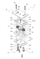
引戸ガイド装置Aは、図3に示すように、取付体20と、取付体20に組み付ける作動操作ピン21、回転リング22およびガイドピン23と、ガイドピン23の回転ストッパを兼ねる上プレート25とを備えた構成になっている。
As shown in FIG. 3, the sliding door guide device A includes a
取付体20は、同じ外形サイズで共に矩形な、金属製の下プレート26およびアングル板24と、樹脂製のライナー27とからなる。下プレート26は、長さ方向左右両端寄りにピン挿通穴26a・26bが設けられている。アングル板24は、幅方向両側を曲げ起こし、そこに突当て凸部24aを形成すると共に、平板部において、下プレート26のピン挿通穴26a・26bと各々対応する位置に、軸挿通穴24b・24cを設けてなる。ライナー27は、回転リング22の高さに合わせて厚肉に形成すると共に、そこに大きなギヤ嵌め込み穴28をあけて成形してなる。ギヤ嵌め込み穴28は、中心に大歯車の減速ギヤ29の外形に合わせてあけた穴部28aと、その図中左右両隣にそれぞれ回転リング22と回転伝達ギヤ30の外形に合わせてあけた穴部28b・28cを連設した穴形状になっている。回転伝達ギヤ30は、外形が略円筒状の歯車状に成形して外周に歯部30aを刻設する一方、内周に雌ねじ穴30bを螺設してなる。
The
作動操作ピン21は、ネジ形軸状をなし、その軸部の頭部寄り外周に、ねじ部21aを螺設してなる。回転リング22は、回転伝達ギヤ30と同様な、外形が略円筒状の歯車状に成形して外周に歯部22aを刻設する一方、内周に雌ねじ穴22bを螺設してなる。ガイドピン23は、ネジ形軸状をなすが、外周面には、特に軸方向に切り溝23aを設けると共に、先端部23b側を除いた部位にねじ部23cを螺設してなる。一方、上プレート25は、アングル板24より外形サイズの大きい矩形な金属板で、下プレート26とアングル板24に有するガイドピン23用のピン挿通穴26a・24bと対応する位置に、軸挿通穴35を設けると共に、作動操作ピン21用のピン挿通穴26b・24cと対応する位置に、軸挿通穴36を設けている。一方の軸挿通穴35には、穴縁に、ガイドピン23の切り溝23aに合わせて、それに係合可能に凸状の回転規制リブ35aが設けられている。
The
斯かる部品構成の引戸ガイド装置Aは、図4に示すように、下プレート26上にライナー27を重ね合わせ、ギヤ嵌め込み穴28の穴部28a・28b・28c内に、それぞれ減速ギヤ29と回転リング22および回転伝達ギヤ30を嵌め込み、相互に噛み合わせて回転伝達手段たるギヤ列を形成する。そして図5に示すように、ライナー27を、下プレート26とアングル板24間に挟んでねじ止めして取付体20を形成し、ピン挿通穴24a・26a、24b・26bにそれぞれガイドピン23と作動操作ピン21を挿通し、ガイドピン23は回転リング22の雌ねじ穴23bに螺合し、作動操作ピン21は回転伝達ギヤ30の雌ねじ穴30bに螺合して取付体20に組み付け、両ピン21・23を取付体20で回転可能に保持した装置本体40を組み立てる。それから、アングル板24の突当て凸部24a上に上プレート25を載せて被せ、突出させた作動操作ピン21の先端を、ピン挿通穴36に係合する一方、ガイドピン23をピン挿通穴35に挿通させて切り溝23aに回転規制リブ35aを係合させて、図6に示すように、上プレート25を、止めねじ39で装置本体40にねじ止めすれば、引戸ガイド装置Aが組み立てられてなる。
As shown in FIG. 4, the sliding door guide device A having such a component structure has a
斯かる組立構成の引戸ガイド装置Aは、作動操作ピン21を回転操作すると、この作動操作ピン21の回転を、それと同軸の回転伝達ギヤ30と噛み合う減速ギヤ29で減速しながら回転リング22へ伝達し、これを回転させる。すると、回転リング22に螺合したガイドピン23は、切り溝23aに回転規制リブ35aが係合して上プレート25で回転規制されているため、回転リング22の回転力に基づき図中上下に軸移動する。こうしてガイドピン23が、作動操作ピン21の正逆回転操作方向に応じて、上プレート25から出没可能な構成になっている。
In the sliding door guide device A having such an assembly configuration, when the
そこで、図示扉開口位置調整システムにおいて、引戸ガイド装置Aを一対備え、図1に示すように下枠部12の取付フレーム15に設置する。その場合、引戸ガイド装置A・Aは、引戸パネルPが左右に開口部S1・S2を開けた中間の基準位置にあるとき、ガイド溝19の長さ方向左右両端部位とそれぞれ対応する下方位置に設置する。引戸ガイド装置A・Aを取付フレーム15に取り付けるときは、図7に示すように、各装置本体40を、左右の取付穴15a・15bに通して溝形の取付フレーム15内に入れ、ガイドピン23の先端部23bが、ガイド溝19の長さ方向左右の穴端面19a・19bに近接した状態で、取付フレーム15に内設する一方、上プレート25を、取付穴15a・15b位置において、取付フレーム15の上面板部15c上に載せて装置本体40に被せる。そして、突出させた作動操作ピン21の先端を、ピン挿通穴36に係合する一方、ガイドピン23は、図8に示すように、ピン挿通穴35に挿通させて切り溝23aに回転規制リブ35aを係合させ、上プレート25は、アングル板24とで取付フレーム15の上面板部15cを挟んでねじ止めする。そこで、扉開口位置調整システムでは、引戸パネルPの脇から、たとえばドライバ等を用い、上向きのピン先端において作動操作ピン21を回転操作すると、この作動操作ピン21の回転に従って回転リング22が回転する一方、回転規制状態のガイドピン23が回転リング22の回転力に基づき引戸スライド移動方向と直交する上下方向に軸移動し、作動操作ピン21の正逆回転操作方向に応じて、先端部23bがガイド溝19に対し係脱する構成になっている。
Therefore, in the illustrated door opening position adjustment system, a pair of sliding door guide devices A are provided and installed on the
したがって、図示扉開口位置調整システムでは、図1に示すように、左右の引戸ガイド装置A・Aにおいて、作動操作ピン21を回動操作し、共にガイドピン23を突出させて、ガイド溝19の左右穴端面19a・19bに係合させると、引戸パネルPのスライド移動を規制し、引戸パネルPを、左右に対称な開口部S1・S2を開けた中間の基準位置に位置決め調整することができる。
Therefore, in the illustrated door opening position adjusting system, as shown in FIG. 1, in the left and right sliding door guide devices A and A, the
一方、例えば開口部の使用態様など必要に応じて、図中右の片側にのみ開口部を形成する場合は、図9(A)に示すように、図中左側の引戸ガイド装置Aは、ガイドピン23をガイド溝19に係合させて引戸パネルPの右方向へのスライド移動を規制する一方、図中右側の引戸ガイド装置Aは、作動操作ピン21を回動操作してガイドピン23を引っ込めて、引戸パネルPの左方向へのスライド移動規制を解除する。しかる後、基準位置にある引戸パネルPを、ガイド溝19に沿ってスライド移動させて、図9(B)に示すように、図中右の片側にのみ大きな開口部S3の開いた一側の片寄せ位置に止めて位置決め調整する。
On the other hand, for example, when the opening is formed only on one side on the right side in the drawing as required, such as the usage mode of the opening, as shown in FIG. 9A, the sliding door guide device A on the left side in the drawing is a guide. While the sliding movement of the sliding door panel P in the right direction is restricted by engaging the
他方、反対に、図中左の片側にのみ開口部を形成する場合は、図10(A)に示すように、図中右側の引戸ガイド装置Aは、ガイドピン23をガイド溝19に係合させて引戸パネルPの左方向へのスライド移動を規制する一方、図中左側の引戸ガイド装置Aは、作動操作ピン21を回動操作してガイドピン23を引っ込めて、引戸パネルPの右方向へのスライド移動規制を解除する。しかる後、引戸パネルPを、ガイド溝19に沿ってスライド移動させれば、図10(B)に示すように、図中左の片側にのみ大きな開口部S4の開いた他側の片寄せ位置に止めて位置決め調整することができる。
On the other hand, when the opening is formed only on one side on the left side in the figure, the sliding door guide device A on the right side in the figure engages the
ところで、上述した図示例の扉開口位置調整システムでは、引戸パネルPが1枚であったが、図11に示すように、戸枠T内に規定される開口部が大きく横長なような場合には、引戸パネルを2枚備え、引戸パネルP1・P2を、引戸ガイド装置A1〜A4によって左右に開口部S1・S2のあいた中間の基準位置と、それぞれ片側に1つ開口部があいた左右の片寄せ位置とに位置決めガイドし、戸枠T内での開口位置を必要に応じて調整する構成にすることもできる。 By the way, in the door opening position adjustment system of the illustrated example described above, there is one sliding door panel P. However, as shown in FIG. 11, the opening defined in the door frame T is large and horizontally long. Is equipped with two sliding door panels, and the sliding door panels P1 and P2 are separated by a sliding door guide device A1 to A4 at the middle reference position between the opening S1 and S2 on the left and right, and the left and right pieces each having one opening on one side. It is also possible to use a configuration that guides positioning to the close position and adjusts the opening position in the door frame T as necessary.
図示他例では、引戸パネルP1・P2が左右に開口部S1・S2を開けた中間の基準位置にあるとき、各々のガイド溝19の長さ方向左右両端部位とそれぞれ対応する下方位置において、それぞれ引戸ガイド装置A1〜A4を、戸枠Tの取付フレーム15に設置する。
In the illustrated other example, when the sliding door panels P1 and P2 are in the middle reference position where the openings S1 and S2 are opened on the left and right, respectively in the lower positions corresponding to the left and right end portions in the length direction of the
図示他例の扉開口位置調整システムでは、引戸ガイド装置A1〜A4において、共にガイドピン23を突出し、各ガイド溝19の左右穴端面19a・19bに係合させて引戸パネルP1・P2のスライド移動を規制し、引戸パネルP1・P2を、左右に開口部S1・S2を開けた中間の基準位置に位置決め調整する。
In the door opening position adjustment system of the other example shown in the figure, in the sliding door guide devices A1 to A4, both guide pins 23 protrude and engage with the left and right hole end surfaces 19a and 19b of each
一方、前述のように必要に応じ、図中右の片側にのみ開口部を形成する場合は、図12に示すように、図中最も左端に設置の引戸ガイド装置A1は、ガイドピン23をガイド溝19に係合させて引戸パネルP1・P2の右方向へのスライド移動を規制する一方、残りの引戸ガイド装置A2・A3・A4は、それぞれ作動操作ピン21を回動操作してガイドピン23を引っ込めて、引戸パネルPの左方向へのスライド移動規制を解除する。しかる後、基準位置にある引戸パネルP1・P2を、各々のガイド溝19に沿ってスライド移動させて、図13に示すように、図中右の片側にのみ大きな開口部S3の開いた一側の片寄せ位置に止めて位置決め調整する。
On the other hand, as described above, if the opening is formed only on one side on the right side in the drawing, the sliding door guide device A1 installed at the leftmost side in the drawing guides the
他方、反対に、図中左の片側にのみ開口部を形成する場合は、図14に示すように、図中最も右端に設置の引戸ガイド装置A4は、ガイドピン23をガイド溝19に係合させて引戸パネルP1・P2の左方向へのスライド移動を規制する一方、残りの引戸ガイド装置A1〜A3は、作動操作ピン21を回動操作してガイドピン23を引っ込めて、引戸パネルP1・P2の右方向へのスライド移動規制を解除する。しかる後、引戸パネルP1・P2を、各々のガイド溝19に沿ってスライド移動させれば、図14に示すように、図中左の片側にのみ大きな開口部S4の開いた他側の片寄せ位置に止めて位置決め調整することができる。
On the other hand, when the opening is formed only on the left side in the figure, the sliding door guide device A4 installed at the rightmost end in the figure engages the
ところで、上述した扉開口位置調整システムでは、上記引戸パネルの左右両側又はいずれか片側において、たとえば開き戸や折り戸などの扉を引戸パネルと面一に戸枠Tに付設し、引戸パネルの左右に形成される開口部を、適宜に開閉する構成にすることもできる。 By the way, in the door opening position adjustment system described above, doors such as hinged doors and folding doors are attached to the door frame T flush with the sliding door panel on either the left or right side or any one side of the sliding door panel. The formed opening can be configured to open and close appropriately.
なお、以上の図示例において、上記引戸ガイド装置は、作動操作ピン21の回転をギヤ列を介して回転リング22へ伝達する構成であったが、それに限らず、回転ベルトなど、各種の回転伝達手段を用いて回転リング22へ回転伝達する構成にすることもできるのは、勿論である。
In the above illustrated example, the sliding door guide device is configured to transmit the rotation of the
A・A1〜A4 引戸ガイド装置
P・P1・P2 引戸パネル
S・S1〜S4 開口部
T 戸枠
10 上枠部
12 下枠部
17 引戸パネルの下端面
19 ガイド溝
20 取付体
21 作動操作ピン
22 回転リング
22b 回転リングの雌ねじ穴
23 ガイドピン
23a 切り溝
23c ねじ部
25 上プレート(回転ストッパ)
35a 回転規制リブ
A · A1 to A4 Sliding door guide device P · P1 · P2 Sliding door panel S · S1 to S4 Opening portion
35a Rotation restriction rib
Claims (1)
前記引戸パネルには、その下端面に、左右の前記片寄せ位置へスライドする移動ストロークに合わせた長さのガイド溝を設ける一方、
前記引戸ガイド装置は、
前記引戸パネルが中間の基準位置にあるとき、前記ガイド溝の長さ方向左右両端部位とそれぞれ対応する下方位置において、前記下枠部に取り付けてなり、
取付体と、その取付体で回転自在に保持する作動操作ピンと、回転中心に雌ねじ穴を螺設し、該雌ねじ穴の中心軸線を前記作動操作ピンと平行な向きにして前記取付体で回転可能に保持すると共に前記作動操作ピンと回転伝達手段を介して回転可能に連結した回転リングと、外周に該回転リングの前記雌ねじ穴と螺合するねじ部を設け、前記取付体で軸移動可能に支持するガイドピンと、そのガイドピンに掛け止めて該ガイドピンの軸回転を常時規制する回転ストッパとを備え、
前記作動操作ピンの回転操作に従って前記回転リングが回転すると、回転規制状態の前記ガイドピンが、前記回転リングの回転力に基づき引戸スライド移動方向に対する上下方向に軸移動して前記ガイド溝に対し係脱する構成にしてなることを特徴とする、扉開口位置調整システム。
A sliding door that suspends a sliding door panel having a width shorter than the length of the upper frame portion on the ceiling side upper frame portion of the door frame so as to be slidable left and right while positioning the moving position of the sliding door panel on the floor side lower frame portion. A guide device is installed, and the sliding door guide device positions and guides the sliding door panel to an intermediate reference position having openings on the left and right sides thereof, and a left and right shift position having openings on only one side, and the door frame. A door opening position adjustment system that adjusts the opening position in the interior as needed,
The sliding door panel is provided with a guide groove having a length corresponding to a moving stroke that slides to the left and right side-shifted positions on the lower end surface thereof,
The sliding door guide device is
When the sliding door panel is at an intermediate reference position, the guide groove is attached to the lower frame portion at lower positions corresponding to the left and right end portions in the length direction of the guide groove,
An attachment body, an operation operation pin that is rotatably held by the attachment body, and a female screw hole is screwed at the center of rotation, and the central axis of the female screw hole is parallel to the operation operation pin so that the attachment body can rotate. A rotating ring that is held and rotatably connected to the operation pin via a rotation transmitting means, and a threaded portion that is screwed into the female screw hole of the rotating ring are provided on the outer periphery, and is supported by the mounting body so that the shaft can move. A guide pin, and a rotation stopper that is fixed on the guide pin and always regulates the shaft rotation of the guide pin,
When the rotating ring rotates in accordance with the rotation operation of the operation operation pin, the rotation-controlled guide pin is axially moved in the vertical direction with respect to the sliding door sliding movement direction based on the rotational force of the rotating ring and is engaged with the guide groove. A door opening position adjustment system, characterized in that it is configured to be removed.
Priority Applications (1)
| Application Number | Priority Date | Filing Date | Title |
|---|---|---|---|
| JP2005032971A JP4086850B2 (en) | 2005-02-09 | 2005-02-09 | Door opening position adjustment system |
Applications Claiming Priority (1)
| Application Number | Priority Date | Filing Date | Title |
|---|---|---|---|
| JP2005032971A JP4086850B2 (en) | 2005-02-09 | 2005-02-09 | Door opening position adjustment system |
Publications (2)
| Publication Number | Publication Date |
|---|---|
| JP2006219863A JP2006219863A (en) | 2006-08-24 |
| JP4086850B2 true JP4086850B2 (en) | 2008-05-14 |
Family
ID=36982368
Family Applications (1)
| Application Number | Title | Priority Date | Filing Date |
|---|---|---|---|
| JP2005032971A Expired - Fee Related JP4086850B2 (en) | 2005-02-09 | 2005-02-09 | Door opening position adjustment system |
Country Status (1)
| Country | Link |
|---|---|
| JP (1) | JP4086850B2 (en) |
Cited By (1)
| Publication number | Priority date | Publication date | Assignee | Title |
|---|---|---|---|---|
| CN102877756A (en) * | 2012-10-30 | 2013-01-16 | 高代国 | Vertically hinged push-pull door |
Families Citing this family (2)
| Publication number | Priority date | Publication date | Assignee | Title |
|---|---|---|---|---|
| ES2323037B1 (en) * | 2007-10-25 | 2010-04-08 | Klein Iberica, S.A. | MECHANISM OF REGULATION FOR SLIDING DOORS. |
| CN106481179A (en) * | 2016-11-24 | 2017-03-08 | 伍志勇 | The slip position-limit mechanism of sliding door of furniture |
-
2005
- 2005-02-09 JP JP2005032971A patent/JP4086850B2/en not_active Expired - Fee Related
Cited By (2)
| Publication number | Priority date | Publication date | Assignee | Title |
|---|---|---|---|---|
| CN102877756A (en) * | 2012-10-30 | 2013-01-16 | 高代国 | Vertically hinged push-pull door |
| CN102877756B (en) * | 2012-10-30 | 2014-07-30 | 高代国 | Vertically hinged push-pull door |
Also Published As
| Publication number | Publication date |
|---|---|
| JP2006219863A (en) | 2006-08-24 |
Similar Documents
| Publication | Publication Date | Title |
|---|---|---|
| US7121618B2 (en) | Sunroof apparatus | |
| JP5993593B2 (en) | Sunshade equipment | |
| US20140366449A1 (en) | Door opening and closing apparatus | |
| JP2005336888A (en) | Opening/closing body interlocking device | |
| KR20140074590A (en) | Regulator Structure for a Curtain Integrated Door | |
| JP4086850B2 (en) | Door opening position adjustment system | |
| US20210025224A1 (en) | Shutter panel with an automatic louver closure assembly and related damping features | |
| EP1331346B1 (en) | Automatic opening and closing apparatus for vehicle | |
| JPH10196252A (en) | Blind device | |
| JP2004316917A (en) | Damping device for furniture moving part | |
| KR20220163755A (en) | Door hinge device for vehicles | |
| JP2008248654A (en) | Door body guide device for sliding door | |
| WO2012011330A1 (en) | Door opening/closing mechanism and refrigerator | |
| EP2921624B1 (en) | Fitting | |
| EP2921632A1 (en) | Sash | |
| US9822575B2 (en) | Movable body driving device | |
| KR101225044B1 (en) | Apparatus for automatically opening and closing a window | |
| EP2778328A2 (en) | Bi-directional espagnolette gearbox and bi-directional espagnolette mechanism | |
| WO2022012117A1 (en) | Electronically controlled sliding device for photographic device, and locking assembly therefor | |
| JPWO2017056126A1 (en) | Switching device for opening / closing mechanism driving force | |
| EP3049601B1 (en) | Adjustment device | |
| US10947770B2 (en) | Adjusting device for a vehicle part that is movable relative to a body of a vehicle | |
| KR100904231B1 (en) | Hinge apparatus with position fixing device | |
| JP6226806B2 (en) | Hinge positioning structure | |
| JP4152867B2 (en) | Sliding door closing device in the cabinet. |
Legal Events
| Date | Code | Title | Description |
|---|---|---|---|
| A977 | Report on retrieval |
Free format text: JAPANESE INTERMEDIATE CODE: A971007 Effective date: 20080118 |
|
| TRDD | Decision of grant or rejection written | ||
| A01 | Written decision to grant a patent or to grant a registration (utility model) |
Free format text: JAPANESE INTERMEDIATE CODE: A01 Effective date: 20080129 |
|
| A61 | First payment of annual fees (during grant procedure) |
Free format text: JAPANESE INTERMEDIATE CODE: A61 Effective date: 20080219 |
|
| FPAY | Renewal fee payment (event date is renewal date of database) |
Free format text: PAYMENT UNTIL: 20110228 Year of fee payment: 3 |
|
| R150 | Certificate of patent or registration of utility model |
Free format text: JAPANESE INTERMEDIATE CODE: R150 |
|
| FPAY | Renewal fee payment (event date is renewal date of database) |
Free format text: PAYMENT UNTIL: 20110228 Year of fee payment: 3 |
|
| FPAY | Renewal fee payment (event date is renewal date of database) |
Free format text: PAYMENT UNTIL: 20140228 Year of fee payment: 6 |
|
| LAPS | Cancellation because of no payment of annual fees |