JP4084928B2 - Sleeper assembly and its assembly method - Google Patents
Sleeper assembly and its assembly method Download PDFInfo
- Publication number
- JP4084928B2 JP4084928B2 JP2000584143A JP2000584143A JP4084928B2 JP 4084928 B2 JP4084928 B2 JP 4084928B2 JP 2000584143 A JP2000584143 A JP 2000584143A JP 2000584143 A JP2000584143 A JP 2000584143A JP 4084928 B2 JP4084928 B2 JP 4084928B2
- Authority
- JP
- Japan
- Prior art keywords
- shoulder member
- sleeper
- insulator
- rail
- opening
- Prior art date
- Legal status (The legal status is an assumption and is not a legal conclusion. Google has not performed a legal analysis and makes no representation as to the accuracy of the status listed.)
- Expired - Lifetime
Links
Images


Classifications
-
- E—FIXED CONSTRUCTIONS
- E01—CONSTRUCTION OF ROADS, RAILWAYS, OR BRIDGES
- E01B—PERMANENT WAY; PERMANENT-WAY TOOLS; MACHINES FOR MAKING RAILWAYS OF ALL KINDS
- E01B9/00—Fastening rails on sleepers, or the like
- E01B9/02—Fastening rails, tie-plates, or chairs directly on sleepers or foundations; Means therefor
- E01B9/32—Fastening on steel sleepers with clamp members
- E01B9/34—Fastening on steel sleepers with clamp members by resilient steel clips
-
- E—FIXED CONSTRUCTIONS
- E01—CONSTRUCTION OF ROADS, RAILWAYS, OR BRIDGES
- E01B—PERMANENT WAY; PERMANENT-WAY TOOLS; MACHINES FOR MAKING RAILWAYS OF ALL KINDS
- E01B2205/00—Electrical insulation of railway track parts
Landscapes
- Engineering & Computer Science (AREA)
- Mechanical Engineering (AREA)
- Architecture (AREA)
- Civil Engineering (AREA)
- Structural Engineering (AREA)
- Railway Tracks (AREA)
- Machines For Laying And Maintaining Railways (AREA)
- Bridges Or Land Bridges (AREA)
- Load-Engaging Elements For Cranes (AREA)
Description
【0001】
【発明の属する技術分野】
本発明は、鋼製の鉄道枕木へ事前装着するレールクリップ及び絶縁具に関する。
【0002】
【従来の技術】
鋼製の鉄道枕木は長年にわたって広く使用されていて、これは通常みがき帯鋼から形成されるか、製鋼所で適当な横断面に圧延される。鋼の厚さは通常6〜12mmの範囲にある。枕木に肩部材を取付けてレールを配置するための迫台を提供し、正しいレールゲージ幅を維持できるようにする。通常、これらの肩部材はレールを押さえる固定具のための取付部としても働く。固定具は普通のボルトか弾力的なスプリングクリップである。
【0003】
多くの異なった手段が、肩部材を所定位置に固定するのに使用されてきた。これらには、ボルト及びナットや、溶接、枕木の上部を変形させてクリップと共に使用するためのレール迫台を形成してクリップを枕木の上面の貫通穴に固定すること、及び、枕木の上面の穴にかぎ止めされる肩部材を含む。しかしながら、実際の軌道使用においては多くの問題があって、例えばナットが絶えずゆるくなるとか、肩部材の縁部の溶接のまわりで枕木がひび割れするとか、局所的な硬化領域が形成される変形された迫台に隣接して枕木がひび割れするとか、応力の高い領域に貫設された穴の縁部から枕木がひび割れするといった問題があった。
【0004】
肩部材を取付ける最も成功している方法のひとつは、応力が比較的低いような枕木の上部の横方向の中央近くの丸い穴に肩部材をかぎ止めすることである。最も高い応力は、剛性が最も大きい枕木上部の側部縁部の近くに生じる。このタイプの肩部材においては、肩部材の上部の下へ突出するようにして、概略円形の心棒が設けられてその下端からはフックと突起部とが延びている。使用に際しては、フックはレールに向かって延びて、突起部はレールからの遠くへと延びる。
【0005】
【発明が解決しようとする課題】
上述したようなフックタイプの固定は従来技術であって一般に良好に働く。しかしながら、それには、レールを据付ける前にはクリップを一時固定位置にて肩部材に事前装着することができないという、ひとつの重大な不都合がある。
【0006】
鉄道の重要な課題は、新しい軌道を設置したり既存の軌道のレールを交換したりすることに関連する労働コストを減少させることにある。
【0007】
著しい労働コストの減少を得るためのひとつの手段は、枕木の製造プラントにおいて新しい枕木にクリップと絶縁具とレールパッドとを事前装着しておくことであって、これによれば枕木を軌道に配置するときには、ただ単にレールを所定位置に置いて、レールクリップをその最終的な位置に機械的に押込むことだけが必要となる。
【0008】
このようなクリップを事前装着するという特徴は、コンクリートの枕木については公知であるものの、鋼製の枕木のためのかぎ止めする肩部材については、レールと絶縁具とを所定位置に配置するまでは肩部材が実際には枕木にロックされることがないことから、可能ではない。その結果、仮に所定位置のレールなしにクリップを所定位置に押すようにすれば、肩部材が枕木の穴から出てくることになるというかなりの可能性がある。たとえクリップを肩部材に事前に据付けることが可能だとしても、転轍機の衝撃や軌道据付け現場への途上でレール運搬車上で受ける他の振動によって、肩部材は依然として穴から飛出すだろう。
【0009】
事前装着することは、パッドと絶縁具とクリップとを軌道に沿って分配してから手作業で所定位置に構成要素を配置して手で肩部材にクリップを導入するのと比べれば、はるかに費用がかからない。明らかに、この手作業は効率的な処理ではなくて、さらに作業現場を行ったり来たりと移動する労働者の損失時間と軌道へのアクセス時間が制限されていることとのために、労働コストは高い。
【0010】
枕木プラントにおいては、固定されて容易に制御された環境であることから、構成要素の事前装着を大規模に機械化するのが可能である。
従って、クリップと絶縁具と肩部材とが鋼製の枕木に事前装着されて、軌道作業の所望の現場への輸送中にそこに保持されるようにすることが望ましい。
【0011】
【課題を解決するための手段】
本発明のひとつの見地によれば、肩部材を受入れる開口を含むタイプの鋼製の鉄道枕木と共に使用するためのレール絶縁具であって、前記絶縁具はレールと前記肩部材との間に配置され、前記絶縁具は、前記枕木の上面の下側へ延びて前記開口と前記肩部材との壁面間に介在するように前記開口へ入る部材を含み、前記肩部材をその所定位置に維持するようなレール絶縁具が提供される。
【0012】
従って、本発明の実施形態は新規な取付装置を提供し、その絶縁具は枕木の開口に延びて入る突起部ないし差込部を含む。
【0013】
この突起部は枕木と肩部材との間の相対的な動きを防ぐように働くので、輸送中に肩部材と絶縁具とクリップとの組立体が枕木からゆるむことがない。これにより事前装着された枕木を準備することが可能になって、それをレールが固定される準備のできている所定の軌道に配置する。これは、従前の提案に比べて、かなりの労働の節約を提供する。
【0014】
枕木の開口は望ましくは、円形又は卵形の形状である。
部材の形状は望ましくは、開口と開口を貫通する肩部材の部分とのサイズの違いによって生じる開口の空洞を実質的に充填するようになっている。
【0015】
好ましい実施形態では、前記肩部材の対応する一対のフランジないし翼部を受入れるための一対の凹部によって、絶縁具は肩部材に保持される。
【0016】
本発明の他の見地によれば、各レールのための2つの肩部材取付開口を有する鋼製の鉄道枕木を含むような事前装着された枕木組立体であって、各取付開口に関連させて、開口に挿通されて所定位置に配置されるようなフックと突起部とを含む肩部材と、意図するレール位置に近い側において前記肩部材に配置される絶縁具とを組合わせ、前記絶縁具は取付開口内へ延びる突起を含んで、意図するレール位置へ向かうような肩部材の動きを阻止し、レールクリップが前記肩部材の一時固定位置に取付けられて、肩部材と絶縁具とクリップとが前記枕木に保持されるような枕木組立体が提供される。
【0017】
本発明のさらに他の見地によれば、鋼製の鉄道枕木に肩部材とレールクリップと絶縁具とを事前装着する方法であって、前記枕木は各レールのための2つの肩部材取付開口を含み、前記肩部材はフックと突起部とを含むような方法において、前記方法が、
a) 前記肩部材を前記開口へ挿入してこれを回転させて、フックは意図するレール位置へ向かうように、そして突起部は遠ざかるように配置するような段階と、
b) 前記絶縁具を肩部材の意図するレール位置の近くの側に配置して、前記絶縁具は取付開口内へ延びる突起を含み、それにより肩部材の意図するレール位置へ向かう動きを阻止するような段階と、
c) 前記レールクリップを事前装着の一時固定の位置に打込んで、肩部材と絶縁具とクリップとが前記枕木に保持されるようにする段階と、
を備えているような方法が提供される。
【0018】
絶縁具を肩部材に配置する段階は好ましくは、絶縁具の対応する凹部に摺動自在に受入れられるように設けられた肩部材の一対のフランジに、絶縁具をかぶせて摺動させる段階を含む。
【0019】
絶縁具がその配置位置に保持されるのは、事前装着されて一時固定されたクリップがその位置で係合することによる。
以下、添付図面を参照しつつ例示的な実施形態について説明する。
【0020】
【発明の実施の形態】
図1は、本発明の実施形態による完成したレール組立体を示していて、枕木1の上にレール2が設置されている。枕木1の上にレール2を固定するためにレールの両側部の結合要素が使用される。各結合要素は肩部材4とスプリングクリップ5とから構成される。
【0021】
多くの場合にレール2は(信号の目的のために)通電するので、絶縁具は通電しているレールを他のセクションから絶縁するのに使用される。詳細には、絶縁パッド14はレール2から枕木1を絶縁し、肩部材絶縁具3はレール2の下側縁部面から肩部材4を絶縁し、クリップ止端絶縁具5はレール2の上側面から肩部材4を絶縁する。本発明の実施形態によれば、肩部材絶縁具3が下向きに突出した差込部11を有していて(図5)、これが肩部材4とレール2との間において枕木の開口に収まるのがわかる。
【0022】
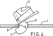
図4に示すように、枕木1は肩部材4のフック7を受け入れるための円形の穴6を有する(図2及び図3)。穴6は十分に大きくてフック7の心棒8と突起部9とを受け入れなければならない。肩部材4は、レールが設置される位置(図4においては左側)へ向かって上部を傾けてからフック7を穴6を通して送り込んで、できるだけ意図するレール位置へ向かって肩部材を動かすことによって穴6に挿入される。次に、肩部材4を正常な位置へ戻すように回転させて、肩部材の上部のベースが枕木1の上部に平坦に載置されるようにする。この動作中に突起部9は枕木1の穴6を通り抜ける。最後に、肩部材を意図するレール位置からできるだけ遠くへ動かして、これにより突起部9を枕木1の穴6に隣接する下面に係合させる。
【0023】
その後、図5に示すように肩部材絶縁具3を所定の位置に配置する。下向きに延びた差込部11を心棒8と枕木1との間に残された空間に嵌入して、それによって肩部材4を枕木の接触点10に押しつけるようにして所定の位置に保持する。
【0024】
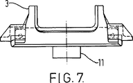
差込部11を備えた肩部材絶縁具3を図6及び図7に多面的に示している。差込部11の形状は穴6の利用可能な空間に合致してそれを実質的に満たすようなものである。穴6は円形とするのが便利だけれども、他の形状の穴も可能である。そして、そのような異なった形状の穴に収まるように、肩部材の心棒8と差込部11とを形成する。例えば、穴6は卵形であって卵形の心棒8と実質的に合致する。これのひとつの利点は、レールを取付ける前における肩部材と事前装着クリップとの組立体の回転できる量を制限することにあって、それにより現場でのレールの組立は確実に簡単になる。また、穴6とこれに合致する心棒8とは正方形または五角形でもよいが、応力集中部として作用するようないかなる鋭利な角部も避けるのが望ましい。
【0025】
絶縁具3には凹部12が設けられていて、肩部材4の翼部を取囲んで下向きに摺動できると共に、垂直を除いたすべての方向について絶縁具3を拘束する。代わりに、絶縁具3は、事前装着位置において、絶縁具3の一部に乗りかかるクリップ5によって所定の位置に保持してもよい。
【0026】
図8は肩部材4を示していて、これにはフック7と心棒8と突起部9とが備えられている。また、側部翼部13も示されていて、これは絶縁具3の対応する凹部12に受け入れられる。
【0027】
図9には枕木の一部を示していて、レールを受けるためのすべての構成要素が所定の位置に事前装着されている。従って、組立体の全体は工場において自動化プロセスによって事前装着することができて、レールが設置される現場に輸送される。いったん所定の位置に設置したならば、スプリングクリップ5を従来の機械的な装置を使用して単にその最終的な位置に押し込んで、組立体をレールに固定する。図1には、この最終的な状態を示している。
【0028】
クリップを事前装着又は一時固定することができるという特徴は、軌道にてレールを交換するときにも有用であって、クリップを取外すための機械はクリップを完全に取除く代わりにクリップを事前装着位置に動かすことができる。このことは、レール交換の後にはただ単にクリップ固定機械を使用してクリップをその最終的な位置に押し戻すことだけが必要であるということを意味していて、従って軌道の脇からクリップや他の構成要素を拾うのに必要な手作業の労働を省く。
【図面の簡単な説明】
【図1】 図1は、本発明の実施形態による枕木とレールの組立体を示す長手軸線を通る模式的な横断面図である。
【図2】 図2は、図1の枕木の一部を示す側面図である。
【図3】 図3は、図1の枕木を示す端面図である。
【図4】 図4は、枕木の上部を通る断面図であって、肩部材のフックが枕木の穴を通して通されている状態での肩部材を示している。
【図5】 図5は、穴内における肩部材の最終的な配置を示している。
【図6】 図6は、本発明の実施形態による絶縁具の底部を上向きに見た図である。
【図7】 図7は、絶縁具の側立面図であって、中央の差込部を示している。
【図8】 図8は、肩部材を示す平面図である。
【図9】 図9は、すべての構成要素が所定位置に事前装着されてレールを受ける準備のできた枕木レール座を示している。[0001]
BACKGROUND OF THE INVENTION
The present invention relates to a rail clip and an insulator that are pre-mounted on a steel railroad sleeper.
[0002]
[Prior art]
Steel railway sleepers have been widely used for many years and are usually formed from brushed steel or rolled into a suitable cross section at a steel mill. The thickness of the steel is usually in the range of 6-12 mm. Provide abutment for placing rails by attaching shoulder members to sleepers so that the correct rail gauge width can be maintained. Usually, these shoulder members also serve as attachments for fixtures that hold the rails. The fixture is an ordinary bolt or a resilient spring clip.
[0003]
Many different means have been used to secure the shoulder members in place. These include bolts and nuts, welding, deforming the top of the sleeper to form a rail abutment for use with the clip and securing the clip to the through hole in the top of the sleeper, and the top of the sleeper Includes a shoulder member that is secured to the hole. However, there are a number of problems in actual track use, such as the nuts becoming constantly loose, the sleepers cracking around the shoulder edge welds, or the local hardened areas are formed. There was a problem that the sleeper cracked adjacent to the abutment or that the sleeper cracked from the edge of the hole penetrating in the high stress area.
[0004]
One of the most successful methods of attaching the shoulder member is to snap the shoulder member into a round hole near the lateral center of the top of the sleeper where the stress is relatively low. The highest stress occurs near the side edge of the top of the sleeper with the greatest stiffness. In this type of shoulder member, a substantially circular mandrel is provided so as to protrude below the upper portion of the shoulder member, and a hook and a protrusion extend from the lower end thereof. In use, the hook extends toward the rail and the protrusion extends away from the rail.
[0005]
[Problems to be solved by the invention]
Hook type fixation as described above is prior art and generally works well. However, it has one serious disadvantage that the clip cannot be pre-mounted on the shoulder member in the temporarily fixed position before the rail is installed.
[0006]
An important issue for railways is to reduce the labor costs associated with installing new tracks and replacing existing track rails.
[0007]
One way to obtain a significant labor cost reduction is to pre-install clips, insulation and rail pads on the new sleepers at the sleeper manufacturing plant, according to which the sleepers are placed on track. When doing so, it is only necessary to place the rail in place and mechanically push the rail clip into its final position.
[0008]
The feature of pre-attaching such a clip is well known for concrete sleepers, but for the shoulder members for staking steel sleepers until the rails and insulators are in place This is not possible because the shoulder member is not actually locked to the sleeper. As a result, if the clip is pushed into place without the rail in place, there is a considerable possibility that the shoulder member will come out of the hole in the sleeper. Even if the clip can be pre-installed on the shoulder member, the shoulder member will still pop out of the hole due to the impact of the rolling mill and other vibrations that are received on the rail vehicle on the way to the track installation site.
[0009]
Pre-installing is much more than distributing the pads, insulators and clips along the track and then manually placing the components in place and manually introducing the clips into the shoulder members. There is no cost. Obviously, this manual process is not an efficient process, and labor costs are limited due to the loss time and access time to the trajectory of workers moving back and forth on the job site. Is expensive.
[0010]
The sleeper plant is a fixed and easily controlled environment, so that the pre-installation of the components can be mechanized on a large scale.
Accordingly, it is desirable that the clip, the insulator, and the shoulder member be pre-mounted on the steel sleeper and held there during transport to the desired site of the track operation.
[0011]
[Means for Solving the Problems]
According to one aspect of the present invention, a rail insulator for use with a steel railroad sleeper of the type including an opening for receiving a shoulder member, the insulator being disposed between the rail and the shoulder member. The insulator includes a member that extends below the upper surface of the sleeper and enters the opening so as to be interposed between the wall surfaces of the opening and the shoulder member, and maintains the shoulder member in its predetermined position. Such a rail insulator is provided.
[0012]
Accordingly, embodiments of the present invention provide a novel attachment device, the insulator of which includes a protrusion or plug that extends into the sleeper opening.
[0013]
This protrusion acts to prevent relative movement between the sleeper and the shoulder member so that the shoulder member, insulator and clip assembly does not loosen from the sleeper during transport. This makes it possible to prepare a pre-mounted sleeper and place it on a predetermined track ready for the rail to be fixed. This provides significant labor savings compared to previous proposals.
[0014]
The sleeper opening is preferably circular or oval in shape.
The shape of the member is preferably adapted to substantially fill the cavity of the opening caused by the difference in size between the opening and the portion of the shoulder member passing through the opening.
[0015]
In a preferred embodiment, the insulator is held on the shoulder member by a pair of recesses for receiving a corresponding pair of flanges or wings of the shoulder member.
[0016]
In accordance with another aspect of the present invention, a pre-mounted sleeper assembly, including a steel railroad sleeper having two shoulder member mounting openings for each rail, associated with each mounting opening. A combination of a shoulder member including a hook and a protrusion that is inserted into the opening and disposed at a predetermined position, and an insulator disposed on the shoulder member on a side close to an intended rail position, Includes a protrusion extending into the mounting opening to prevent movement of the shoulder member toward the intended rail position, and the rail clip is attached to the temporary fixing position of the shoulder member to provide the shoulder member, the insulator, and the clip. A sleeper assembly is provided such that is held by the sleeper.
[0017]
According to still another aspect of the present invention, a method of pre-attaching a shoulder member, a rail clip, and an insulator to a steel railway sleeper, wherein the sleeper has two shoulder member mounting openings for each rail. And the shoulder member includes a hook and a protrusion, the method comprising:
a) inserting the shoulder member into the opening and rotating it to position the hook towards the intended rail position and the protrusion away;
b) placing the insulator on the side of the shoulder member near the intended rail position, the insulator including a protrusion extending into the mounting opening, thereby preventing movement of the shoulder member toward the intended rail position; Such a stage,
c) driving the rail clip into a pre-mounted temporarily fixed position so that the shoulder member, the insulator and the clip are held by the sleeper;
Such a method is provided.
[0018]
Preferably, the step of disposing the insulator on the shoulder member includes the step of sliding the insulator over the pair of flanges of the shoulder member that are slidably received in the corresponding recesses of the insulator. .
[0019]
The insulator is held in its position because the pre-mounted and temporarily secured clip engages in that position.
Hereinafter, exemplary embodiments will be described with reference to the accompanying drawings.
[0020]
DETAILED DESCRIPTION OF THE INVENTION
FIG. 1 shows a completed rail assembly according to an embodiment of the present invention, in which a rail 2 is installed on a sleeper 1. In order to fix the rail 2 on the sleeper 1, connecting elements on both sides of the rail are used. Each coupling element comprises a shoulder member 4 and a spring clip 5.
[0021]
In many cases the rail 2 is energized (for signal purposes), so that the insulator is used to insulate the energized rail from other sections. Specifically, the insulating
[0022]
As shown in FIG. 4, the sleeper 1 has a
[0023]
Thereafter, as shown in FIG. 5, the shoulder member insulator 3 is disposed at a predetermined position. The downwardly extending
[0024]
The shoulder member insulator 3 provided with the
[0025]
The insulator 3 is provided with a
[0026]
FIG. 8 shows the shoulder member 4, which is provided with a hook 7, a
[0027]
FIG. 9 shows a part of a sleeper, with all components for receiving the rails pre-installed in place. Thus, the entire assembly can be pre-installed by an automated process at the factory and transported to the site where the rails are installed. Once in place, the spring clip 5 is simply pushed into its final position using conventional mechanical devices to secure the assembly to the rail. FIG. 1 shows this final state.
[0028]
The feature that the clip can be pre-mounted or temporarily fixed is also useful when replacing the rails on the track, and the machine for removing the clip is a pre-mounted position instead of removing the clip completely. Can be moved to. This means that after a rail change, it is only necessary to push the clip back to its final position using a clip-fixing machine, so that clips and other Eliminates the manual labor required to pick up components.
[Brief description of the drawings]
FIG. 1 is a schematic cross-sectional view through a longitudinal axis showing a sleeper and rail assembly according to an embodiment of the present invention.
FIG. 2 is a side view showing a part of the sleepers of FIG. 1;
FIG. 3 is an end view showing the sleeper of FIG. 1;
FIG. 4 is a cross-sectional view through the top of the sleeper, showing the shoulder member with the hook of the shoulder member being threaded through the hole in the sleeper.
FIG. 5 shows the final placement of the shoulder member within the hole.
FIG. 6 is an upward view of the bottom of the insulator according to the embodiment of the present invention.
FIG. 7 is a side elevational view of the insulator, showing a central plug.
FIG. 8 is a plan view showing a shoulder member.
FIG. 9 shows a sleeper rail seat with all components pre-installed in place and ready to receive the rail.
Claims (6)
a) 前記肩部材(4)を前記開口(6)へ挿入してこれを回転させて、フック(7)は意図するレール位置へ向かうように、そして突起部(9)は遠ざかるように配置するような段階と、
b) 前記絶縁具(3)を肩部材(4)の意図するレール位置の近くの側に配置して、前記絶縁具(3)は前記開口(6)と前記肩部材(4)との壁面間に介在するように取付開口(6)内へ延びる部材(11)を含み、それにより肩部材(4)の意図するレール位置へ向かう動きを阻止するような段階と、
c) 前記レールクリップ(5)を事前装着の一時固定の位置に打込んで、肩部材(4)と絶縁具(3)とクリップ(5)とが前記枕木(1)に保持されるようにする段階と、 を備えていることを特徴とする方法。A method of pre-attaching a shoulder member (4), a rail clip (5), and an insulator (3) to a steel railroad sleeper (1), wherein the sleeper (1) is for each rail (2) In a method comprising two shoulder member mounting openings (6), said shoulder member (4) comprising a hook (7) and a protrusion (9), said method comprising:
a) Insert the shoulder member (4) into the opening (6) and rotate it to position the hook (7) towards the intended rail position and the protrusion (9) away. Such a stage,
b) The insulator (3) is arranged on the side near the intended rail position of the shoulder member (4), and the insulator (3) is a wall surface between the opening (6) and the shoulder member (4). Including a member (11) extending into the mounting opening (6) so as to intervene, thereby preventing movement of the shoulder member (4) toward the intended rail position;
c) The rail clip (5) is driven into a pre-mounted temporarily fixed position so that the shoulder member (4), the insulator (3) and the clip (5) are held by the sleeper (1). And a method characterized by comprising:
Applications Claiming Priority (3)
| Application Number | Priority Date | Filing Date | Title |
|---|---|---|---|
| AUPP7260A AUPP726098A0 (en) | 1998-11-23 | 1998-11-23 | Preloading rail clips in steel sleepers |
| AU7260 | 1998-11-23 | ||
| PCT/GB1999/003833 WO2000031343A1 (en) | 1998-11-23 | 1999-11-17 | Preloading rail clips in steel sleepers |
Publications (3)
| Publication Number | Publication Date |
|---|---|
| JP2002530558A JP2002530558A (en) | 2002-09-17 |
| JP2002530558A5 JP2002530558A5 (en) | 2007-01-11 |
| JP4084928B2 true JP4084928B2 (en) | 2008-04-30 |
Family
ID=3811469
Family Applications (1)
| Application Number | Title | Priority Date | Filing Date |
|---|---|---|---|
| JP2000584143A Expired - Lifetime JP4084928B2 (en) | 1998-11-23 | 1999-11-17 | Sleeper assembly and its assembly method |
Country Status (8)
| Country | Link |
|---|---|
| US (1) | US6499667B1 (en) |
| JP (1) | JP4084928B2 (en) |
| AU (1) | AUPP726098A0 (en) |
| BR (1) | BR9916862A (en) |
| CA (1) | CA2351360C (en) |
| GB (1) | GB2358423B (en) |
| OA (1) | OA11804A (en) |
| WO (1) | WO2000031343A1 (en) |
Families Citing this family (7)
| Publication number | Priority date | Publication date | Assignee | Title |
|---|---|---|---|---|
| DE102004031632A1 (en) * | 2004-06-21 | 2006-01-26 | Bwg Gmbh & Co. Kg | Arrangement for fastening a rail |
| WO2006032072A1 (en) * | 2004-09-21 | 2006-03-30 | Airboss Railway Products Inc | Improved rail clip insulators |
| GB2435285A (en) | 2006-02-21 | 2007-08-22 | Pandrol Ltd | Fastening railway rails |
| MX2012010194A (en) * | 2010-03-03 | 2012-10-01 | Vossloh Werke Gmbh | Hook bolt for fastening rails to hollow sleepers. |
| USD736609S1 (en) * | 2013-01-08 | 2015-08-18 | Pandrol Limited | Clamp shoulder |
| CN108408588A (en) * | 2018-04-25 | 2018-08-17 | 唐山钢铁集团有限责任公司 | A kind of adjustable crane trolley track clamping device |
| USD923465S1 (en) * | 2019-05-02 | 2021-06-29 | Gripple Limited | Cross wire connecting device |
Family Cites Families (6)
| Publication number | Priority date | Publication date | Assignee | Title |
|---|---|---|---|---|
| US5083706A (en) * | 1988-01-28 | 1992-01-28 | Amatek Limited | Concrete sleeper with east-in insert cooperating with a fastener assembly |
| US4967954A (en) * | 1988-12-15 | 1990-11-06 | American Track Systems, Inc. | Rail fastening device |
| GB2228958A (en) | 1989-03-09 | 1990-09-12 | Pandrol Ltd | Rail clip locating device and concrete foundation therefor |
| JP2508758Y2 (en) * | 1991-04-26 | 1996-08-28 | 財団法人鉄道総合技術研究所 | Rail fastening device |
| DE4116306A1 (en) * | 1991-05-15 | 1992-11-19 | Salzgitter Peine Stahlwerke | Securing rail to two parallel cross-sleepers - using pre-mounted fitting watch will accept various screen size and is electrically insulated |
| GB2316702A (en) | 1996-08-28 | 1998-03-04 | British Steel Plc | Spring steel rail clip for use with steel sleeper and insulator |
-
1998
- 1998-11-23 AU AUPP7260A patent/AUPP726098A0/en not_active Abandoned
-
1999
- 1999-11-17 OA OA1200100125A patent/OA11804A/en unknown
- 1999-11-17 GB GB0111057A patent/GB2358423B/en not_active Expired - Lifetime
- 1999-11-17 BR BR9916862-6A patent/BR9916862A/en not_active IP Right Cessation
- 1999-11-17 JP JP2000584143A patent/JP4084928B2/en not_active Expired - Lifetime
- 1999-11-17 CA CA002351360A patent/CA2351360C/en not_active Expired - Lifetime
- 1999-11-17 US US09/856,013 patent/US6499667B1/en not_active Expired - Lifetime
- 1999-11-17 WO PCT/GB1999/003833 patent/WO2000031343A1/en active IP Right Grant
Also Published As
| Publication number | Publication date |
|---|---|
| JP2002530558A (en) | 2002-09-17 |
| AUPP726098A0 (en) | 1998-12-17 |
| GB0111057D0 (en) | 2001-06-27 |
| US6499667B1 (en) | 2002-12-31 |
| GB2358423A (en) | 2001-07-25 |
| BR9916862A (en) | 2001-08-21 |
| GB2358423B (en) | 2002-04-03 |
| WO2000031343A1 (en) | 2000-06-02 |
| CA2351360A1 (en) | 2000-06-02 |
| CA2351360C (en) | 2006-09-26 |
| OA11804A (en) | 2005-08-10 |
Similar Documents
| Publication | Publication Date | Title |
|---|---|---|
| US6954974B2 (en) | Method of constructing a rail track on a concrete slab and a temporary tie plate for use in the method | |
| CS235058B2 (en) | Clamp for fastening of railway rail | |
| US7669779B2 (en) | Rail clip support shoulder | |
| US7690584B2 (en) | Fastener for supporting railroad ties | |
| CA2642109A1 (en) | Railway rail fastening clip | |
| CZ68799A3 (en) | Steel railway sleeper and process for producing thereof | |
| CN102301070B (en) | Railway clip insulator with two stable positions for standby, parked or preloaded position and installed, loaded or final position | |
| JP4084928B2 (en) | Sleeper assembly and its assembly method | |
| MXPA05005891A (en) | An abrasion assembly for supporting railroad ties related. | |
| EP0826826B1 (en) | Fastening railway rails | |
| JP3058592B2 (en) | Rail fastening device with height adjustment function | |
| US4190200A (en) | Rail clip assembly | |
| AU752883B2 (en) | Preloading rail clips in steel sleepers | |
| JP2004190284A (en) | Track vicinity paving method | |
| JP3058594B2 (en) | Rail fastening device with height adjustment function | |
| EP0066995A2 (en) | Two piece rail fastening assemblies for wooden cross ties | |
| US4732320A (en) | Railroad grade crossing with transverse securing splines | |
| US4919330A (en) | Quick release railroad highway crossing | |
| US6398123B1 (en) | Railway fastening anchor and clip | |
| JPH0449202Y2 (en) | ||
| AU772838B2 (en) | A resilient fastening assembly for a rail | |
| JPS6120082Y2 (en) | ||
| KR100681917B1 (en) | Base plate fixing structure | |
| JPH045526Y2 (en) | ||
| RU2436884C2 (en) | Rail plate, rail fastening terminal and rail fastening |
Legal Events
| Date | Code | Title | Description |
|---|---|---|---|
| A521 | Request for written amendment filed |
Free format text: JAPANESE INTERMEDIATE CODE: A523 Effective date: 20061114 |
|
| A621 | Written request for application examination |
Free format text: JAPANESE INTERMEDIATE CODE: A621 Effective date: 20061114 |
|
| A131 | Notification of reasons for refusal |
Free format text: JAPANESE INTERMEDIATE CODE: A131 Effective date: 20070918 |
|
| A521 | Request for written amendment filed |
Free format text: JAPANESE INTERMEDIATE CODE: A523 Effective date: 20071102 |
|
| TRDD | Decision of grant or rejection written | ||
| A01 | Written decision to grant a patent or to grant a registration (utility model) |
Free format text: JAPANESE INTERMEDIATE CODE: A01 Effective date: 20080128 |
|
| A61 | First payment of annual fees (during grant procedure) |
Free format text: JAPANESE INTERMEDIATE CODE: A61 Effective date: 20080218 |
|
| R150 | Certificate of patent or registration of utility model |
Free format text: JAPANESE INTERMEDIATE CODE: R150 Ref document number: 4084928 Country of ref document: JP Free format text: JAPANESE INTERMEDIATE CODE: R150 |
|
| FPAY | Renewal fee payment (event date is renewal date of database) |
Free format text: PAYMENT UNTIL: 20110222 Year of fee payment: 3 |
|
| FPAY | Renewal fee payment (event date is renewal date of database) |
Free format text: PAYMENT UNTIL: 20120222 Year of fee payment: 4 |
|
| R250 | Receipt of annual fees |
Free format text: JAPANESE INTERMEDIATE CODE: R250 |
|
| FPAY | Renewal fee payment (event date is renewal date of database) |
Free format text: PAYMENT UNTIL: 20130222 Year of fee payment: 5 |
|
| R250 | Receipt of annual fees |
Free format text: JAPANESE INTERMEDIATE CODE: R250 |
|
| FPAY | Renewal fee payment (event date is renewal date of database) |
Free format text: PAYMENT UNTIL: 20140222 Year of fee payment: 6 |
|
| R250 | Receipt of annual fees |
Free format text: JAPANESE INTERMEDIATE CODE: R250 |
|
| R250 | Receipt of annual fees |
Free format text: JAPANESE INTERMEDIATE CODE: R250 |
|
| R250 | Receipt of annual fees |
Free format text: JAPANESE INTERMEDIATE CODE: R250 |
|
| R250 | Receipt of annual fees |
Free format text: JAPANESE INTERMEDIATE CODE: R250 |
|
| R250 | Receipt of annual fees |
Free format text: JAPANESE INTERMEDIATE CODE: R250 |
|
| R250 | Receipt of annual fees |
Free format text: JAPANESE INTERMEDIATE CODE: R250 |
|
| R250 | Receipt of annual fees |
Free format text: JAPANESE INTERMEDIATE CODE: R250 |
|
| EXPY | Cancellation because of completion of term |