JP4081239B2 - A device that supplies positive pressure to the subject's airways - Google Patents
A device that supplies positive pressure to the subject's airways Download PDFInfo
- Publication number
- JP4081239B2 JP4081239B2 JP2000535400A JP2000535400A JP4081239B2 JP 4081239 B2 JP4081239 B2 JP 4081239B2 JP 2000535400 A JP2000535400 A JP 2000535400A JP 2000535400 A JP2000535400 A JP 2000535400A JP 4081239 B2 JP4081239 B2 JP 4081239B2
- Authority
- JP
- Japan
- Prior art keywords
- pressure
- subject
- airway
- breathing
- gas
- Prior art date
- Legal status (The legal status is an assumption and is not a legal conclusion. Google has not performed a legal analysis and makes no representation as to the accuracy of the status listed.)
- Expired - Lifetime
Links
Images


Classifications
-
- A—HUMAN NECESSITIES
- A61—MEDICAL OR VETERINARY SCIENCE; HYGIENE
- A61M—DEVICES FOR INTRODUCING MEDIA INTO, OR ONTO, THE BODY; DEVICES FOR TRANSDUCING BODY MEDIA OR FOR TAKING MEDIA FROM THE BODY; DEVICES FOR PRODUCING OR ENDING SLEEP OR STUPOR
- A61M16/00—Devices for influencing the respiratory system of patients by gas treatment, e.g. mouth-to-mouth respiration; Tracheal tubes
- A61M16/20—Valves specially adapted to medical respiratory devices
- A61M16/201—Controlled valves
- A61M16/202—Controlled valves electrically actuated
- A61M16/203—Proportional
- A61M16/205—Proportional used for exhalation control
-
- A—HUMAN NECESSITIES
- A61—MEDICAL OR VETERINARY SCIENCE; HYGIENE
- A61M—DEVICES FOR INTRODUCING MEDIA INTO, OR ONTO, THE BODY; DEVICES FOR TRANSDUCING BODY MEDIA OR FOR TAKING MEDIA FROM THE BODY; DEVICES FOR PRODUCING OR ENDING SLEEP OR STUPOR
- A61M16/00—Devices for influencing the respiratory system of patients by gas treatment, e.g. mouth-to-mouth respiration; Tracheal tubes
- A61M16/0051—Devices for influencing the respiratory system of patients by gas treatment, e.g. mouth-to-mouth respiration; Tracheal tubes with alarm devices
-
- A—HUMAN NECESSITIES
- A61—MEDICAL OR VETERINARY SCIENCE; HYGIENE
- A61M—DEVICES FOR INTRODUCING MEDIA INTO, OR ONTO, THE BODY; DEVICES FOR TRANSDUCING BODY MEDIA OR FOR TAKING MEDIA FROM THE BODY; DEVICES FOR PRODUCING OR ENDING SLEEP OR STUPOR
- A61M16/00—Devices for influencing the respiratory system of patients by gas treatment, e.g. mouth-to-mouth respiration; Tracheal tubes
- A61M16/0057—Pumps therefor
- A61M16/0066—Blowers or centrifugal pumps
- A61M16/0069—Blowers or centrifugal pumps the speed thereof being controlled by respiratory parameters, e.g. by inhalation
-
- A—HUMAN NECESSITIES
- A61—MEDICAL OR VETERINARY SCIENCE; HYGIENE
- A61M—DEVICES FOR INTRODUCING MEDIA INTO, OR ONTO, THE BODY; DEVICES FOR TRANSDUCING BODY MEDIA OR FOR TAKING MEDIA FROM THE BODY; DEVICES FOR PRODUCING OR ENDING SLEEP OR STUPOR
- A61M16/00—Devices for influencing the respiratory system of patients by gas treatment, e.g. mouth-to-mouth respiration; Tracheal tubes
- A61M16/021—Devices for influencing the respiratory system of patients by gas treatment, e.g. mouth-to-mouth respiration; Tracheal tubes operated by electrical means
- A61M16/022—Control means therefor
- A61M16/024—Control means therefor including calculation means, e.g. using a processor
-
- A—HUMAN NECESSITIES
- A61—MEDICAL OR VETERINARY SCIENCE; HYGIENE
- A61M—DEVICES FOR INTRODUCING MEDIA INTO, OR ONTO, THE BODY; DEVICES FOR TRANSDUCING BODY MEDIA OR FOR TAKING MEDIA FROM THE BODY; DEVICES FOR PRODUCING OR ENDING SLEEP OR STUPOR
- A61M16/00—Devices for influencing the respiratory system of patients by gas treatment, e.g. mouth-to-mouth respiration; Tracheal tubes
- A61M16/20—Valves specially adapted to medical respiratory devices
- A61M16/201—Controlled valves
- A61M16/202—Controlled valves electrically actuated
- A61M16/203—Proportional
- A61M16/204—Proportional used for inhalation control
-
- A—HUMAN NECESSITIES
- A61—MEDICAL OR VETERINARY SCIENCE; HYGIENE
- A61M—DEVICES FOR INTRODUCING MEDIA INTO, OR ONTO, THE BODY; DEVICES FOR TRANSDUCING BODY MEDIA OR FOR TAKING MEDIA FROM THE BODY; DEVICES FOR PRODUCING OR ENDING SLEEP OR STUPOR
- A61M16/00—Devices for influencing the respiratory system of patients by gas treatment, e.g. mouth-to-mouth respiration; Tracheal tubes
- A61M16/0057—Pumps therefor
- A61M16/0066—Blowers or centrifugal pumps
-
- A—HUMAN NECESSITIES
- A61—MEDICAL OR VETERINARY SCIENCE; HYGIENE
- A61M—DEVICES FOR INTRODUCING MEDIA INTO, OR ONTO, THE BODY; DEVICES FOR TRANSDUCING BODY MEDIA OR FOR TAKING MEDIA FROM THE BODY; DEVICES FOR PRODUCING OR ENDING SLEEP OR STUPOR
- A61M16/00—Devices for influencing the respiratory system of patients by gas treatment, e.g. mouth-to-mouth respiration; Tracheal tubes
- A61M16/0003—Accessories therefor, e.g. sensors, vibrators, negative pressure
- A61M2016/0015—Accessories therefor, e.g. sensors, vibrators, negative pressure inhalation detectors
- A61M2016/0018—Accessories therefor, e.g. sensors, vibrators, negative pressure inhalation detectors electrical
- A61M2016/0021—Accessories therefor, e.g. sensors, vibrators, negative pressure inhalation detectors electrical with a proportional output signal, e.g. from a thermistor
-
- A—HUMAN NECESSITIES
- A61—MEDICAL OR VETERINARY SCIENCE; HYGIENE
- A61M—DEVICES FOR INTRODUCING MEDIA INTO, OR ONTO, THE BODY; DEVICES FOR TRANSDUCING BODY MEDIA OR FOR TAKING MEDIA FROM THE BODY; DEVICES FOR PRODUCING OR ENDING SLEEP OR STUPOR
- A61M16/00—Devices for influencing the respiratory system of patients by gas treatment, e.g. mouth-to-mouth respiration; Tracheal tubes
- A61M16/0003—Accessories therefor, e.g. sensors, vibrators, negative pressure
- A61M2016/003—Accessories therefor, e.g. sensors, vibrators, negative pressure with a flowmeter
- A61M2016/0033—Accessories therefor, e.g. sensors, vibrators, negative pressure with a flowmeter electrical
- A61M2016/0036—Accessories therefor, e.g. sensors, vibrators, negative pressure with a flowmeter electrical in the breathing tube and used in both inspiratory and expiratory phase
-
- A—HUMAN NECESSITIES
- A61—MEDICAL OR VETERINARY SCIENCE; HYGIENE
- A61M—DEVICES FOR INTRODUCING MEDIA INTO, OR ONTO, THE BODY; DEVICES FOR TRANSDUCING BODY MEDIA OR FOR TAKING MEDIA FROM THE BODY; DEVICES FOR PRODUCING OR ENDING SLEEP OR STUPOR
- A61M16/00—Devices for influencing the respiratory system of patients by gas treatment, e.g. mouth-to-mouth respiration; Tracheal tubes
- A61M16/0003—Accessories therefor, e.g. sensors, vibrators, negative pressure
- A61M2016/003—Accessories therefor, e.g. sensors, vibrators, negative pressure with a flowmeter
- A61M2016/0033—Accessories therefor, e.g. sensors, vibrators, negative pressure with a flowmeter electrical
- A61M2016/0039—Accessories therefor, e.g. sensors, vibrators, negative pressure with a flowmeter electrical in the inspiratory circuit
Description
【0001】
関連出願に対する相互参照
本願は、1994年6月3日に出願された特許出願番号第08/253496号で現在米国特許第5,535,738号の一部継続出願として、1996年6月15日に出願された特許出願番号第08/679898号の一部継続出願である。
【0002】
【発明の背景】
1.技術分野
本発明は、呼吸及び/又は心臓疾患を治療する方法と装置、特に、閉塞性睡眠無呼吸症候群、慢性閉塞性肺疾患、鬱血性心不全及び他の呼吸器疾患及び/又は呼吸疾患を治療するため、呼吸サイクルの少なくとも一部間で被験者(患者)の気道に呼吸気体の圧力を供給する方法と装置に関する。
【0003】
2.関連技術の説明
閉塞性睡眠無呼吸症候群(OSAS)の間、被験者が眠る間に気道は狭窄状態及び/又は虚脱状態(圧潰状態)となる傾向がある。連続的気道正圧(連続的気道正圧(CPAP))療法は、気道を強制的に開放する圧力を供給して狭窄状態を回避する副木的機能がある。連続的気道正圧(CPAP)では、気道開放圧力は、睡眠研究の間、気道の狭窄を防止するのに十分な大きさに最適化され一定に保持される。一定の強制気道開放圧力、即ち連続的気道正圧(Continuous Positive Airway Pressure-CPAP)を与えることは、圧潰気道により提起される問題の単純な解決法である。しかしながら、この解決法は、大部分の呼吸サイクルに対して気道の開放を支持するのに必要な圧力より高い圧力を被験者に供給しなければならない。
【0004】
吸気作用の間、肺内で形成される圧力は、鼻での圧力より低い。この圧力差により、肺への空気流れを発生する。この圧力差により、肺と鼻を接続する気道の気圧勾配を形成する。即ち、被験者の肺及び気道は大気圧(周辺圧力)より低いか負圧であるのに対し、鼻は通常大気圧(周辺圧力)である。この負圧は、気道に作用して、気道を圧潰する。吸気作用により発生する低周囲圧力を除去して、気道組織の構造、筋肉の緊張状態及び身体状態から生じるいかなる機械的な圧潰力を克服するのに必要なレベルまで全呼吸系の圧力レベルを上昇するように、連続的気道正圧(CPAP)のレベルが設定される。2レベルの気道正圧力系の吸入圧力、即ち気道吸気正圧(IPAP-Inspiratory Positive Airway Pressure)は、類似の方法で設定される。
【0005】
呼気の間では、肺の内部と身体の外部との間に正圧勾配が存在する。呼気の間では、正圧勾配により気道が開放状態に保持される。呼気の終端に気圧勾配はほぼ本質的にゼロとなり、呼吸気体の流れは同様にゼロとなるので、気道は呼吸作用の影響を受けない。呼気の終端では、気道のいかなる圧潰も、気道組織の構造、筋肉の緊張状態及び身体状態の機能である。2レベルの装置は、呼気の終端で気道の支持に必要な呼気圧力を供給しようとする。
【0006】
呼吸サイクルの経過中に、一対の肺と身体の外部との間の圧力勾配が一定でない点に留意する必要がある。吸気圧力勾配は、吸気開始時のゼロから負ピーク値に向かい、その後、吸気作用の終端でゼロに上昇する。呼気圧力勾配は、呼気開始時のゼロからピーク値に向かい、その後、呼気の終端でゼロに戻る。呼吸サイクルを通じて気圧勾配が変化するので、理想的には気道圧潰の克服に必要な圧力は呼吸サイクルを通じて変化しなければならない。
【0007】
従来の連続的気道正圧(CPAP)療法は、圧力条件での前記変化を無視して、単一の圧力レベルでの療法となる。従来の連続的気道正圧(CPAP)は単に最悪の場合の治療パラメータである吸気作用の間のピーク圧力条件のみに基づくため、連続的気道正圧(CPAP)の圧力がむしろ大ざっぱであり、最適な療法からほど遠い。
【0008】
従来の連続的気道正圧(CPAP)の前進を表す2レベルの気道正圧(2レベルのPositive Air Pressure-PAP)の療法は、異なる圧力条件を利用して、呼気の間、圧力を下げる。にもかかわらず、2レベルの気道吸気正圧(IPAP)は、なお吸気作用の間に遭遇する被験者のピークの必要に基づいて、全吸気段階を通じて一定のままであるから、2レベルの療法も最適の治療を行うことができない。また、2レベルの治療の間、呼気状態気道圧力(Expiratory Position Airway Pressure-EPAP)は、一定のままで、呼気の終端での開放支持要求にのみに専ら関連する。
【0009】
睡眠無呼吸症候群(OSAS)に加えて、気道正圧治療(例えば2レベルの気道正圧療法)は、例えば慢性閉塞性肺疾患(Chronic Obstructive Pulmonary Disorder-COPD)等の他の呼吸疾患の治療に適用された。しかし、このモードに関する治療課題の1つは、被験者が吸気流を停止することが困難である点にある。この現象は、吸気作用の終端で被験者の呼吸抵抗を克服する必要のある圧力と、印加される気道吸気正圧(IPAP)の相違のために発生する。前者の圧力が概して後者の圧力を上回るので、吸気作用の終端での「剰余」気道吸気正圧(IPAP)は被験者の肺に対する不快で潜在的に有害な超膨張を招来する。
【0010】
逆に、吸気流を開始するために、慢性閉塞性肺疾患(COPD)の被験者は、呼吸系の入口で周囲圧力に満たない圧力まで、肺内部の圧力を減少しなければならない。「自動呼気終端圧力」として共通に公知の条件のために、被験者の肺の圧力は、一般的に呼気の終端では周辺圧力より高い。従って、被験者の呼吸する筋肉は、肺への空気流が発生する前に、肺を拡張する追加の動作を実行して、肺の圧力を周辺圧力のレベルより低く減圧しなければならない。呼気終端圧力(Positive End Expiratory Pressure-PEEP)として公知の抵抗性逆圧力によって、自動呼気終端圧力を一般的に取り扱わなければならない。呼気終端圧力(PEEP)は、被験者の自動呼気終端圧力(Auto-PEEP)直下のレベルに設定され、吸気流の開始に必要な呼吸動作量を低減することができる。
【0011】
例えば圧力保持、連続的気道正圧(CPAP)又は2レベル療法等の従来の治療法では、全呼気段階、例えば2レベルの気道正圧(PAP)療法の呼気状態気道圧力(EPAP)段階を通じて同一の圧力を印加することにより呼気終端圧力(PEEP)を達成できる。呼気状態気道圧力(EPAP)が呼気終端圧力(PEEP)と同義でない点に留意する必要がある。呼気状態気道圧力(EPAP)は呼気の全体にわたり被験者に供給される一定の圧力を示すのに対し、呼気終端圧力(PEEP)は正の呼気終端圧力を示す。自明であるが、呼気終端圧力(PEEP)は、呼気の終端で必要なだけである。このように、呼気サイクルを通じて呼気状態気道圧力(EPAP)を実施すると、満足な呼気終端圧力(PEEP)を維持できる反面、呼気の間に被験者が実行しなければならない呼吸動作には不都合な影響を与える。
【0012】
連続的気道正圧(CPAP)及び2レベルの気道正圧(PAP)に加えて、被験者の呼吸動作を誘発し、無用にし、援助し及び/又は抵抗する方法及び装置の集合機能を付与する睡眠無呼吸症候群(OSAS)、慢性閉塞性肺疾患(COPD)及び他の呼吸疾患の治療を含む臨床の調査及び/又は治療の適用に対する他のシステムが提案された。これらのシステムには、例えば、これらに限られないが、吸気流及び/又は呼気流、吸気圧及び/又は呼気圧力、周期的容積及び鼾音等の気道障害を表す徴候を含む被験者の呼吸活動に関連する一つ又はそれ以上の要因に応答する所定の機能を実行するものもある。また、経胸腔的に目的を達成するものもあれば、正圧又は負圧で被験者の気道に直接空気を供給するものもある。
【0013】
「鉄肺」と一般に呼称するこの種の装置の初期の例は、「肺気腫での呼吸に対する機械的補助、患者により制御されたサーボ式人工呼吸装置の成果」と題する刊行物(ジェームズ・アール・ハリース(医学博士)及びジョン・エム・タイラー(医学博士)共著、アメリカ医学ジャーナルにて公表、1964年1月出版、第36巻、第68〜78頁)に掲載された。前記刊行物に提案された鉄肺は、広い加圧室内で着座する被験者の身体の外面に対して経胸腔的な圧力を印加し又は除去することにより、被験者の呼吸作用(即ち、鉄肺は、吸気作用の間負圧を印加し、呼気作用の間に周辺空気圧又は正圧を印加する)を補助する人工呼吸装置である。その日のために精巧に作動する人工呼吸装置は、具体的には、被験者の自然発生的な一呼吸を構成する検出呼吸の気体流量又は気体容積に応答して絶えず内部室圧力を制御する。実際に、被験者の胸部に取り付けられる歪み計呼吸曲線記録器から得られる信号は、気体容積に比例するもの、吸気流量に比例するもの及び呼気流量に比例するものの3つの成分に電気的に分割される。各成分は、個別の利得制御装置に割り当てられる。その後、成分信号は再結合され、送風機と加圧室との間に設けられた電動可変バルブにより加圧室内の圧力が制御される。
【0014】
所期の目的に対して有効であるが、通常、サイズが大きく、取扱が煩雑で、コストが高くかつ応用範囲が制限されるため、前記及び他の鉄肺装置は嫌われる。即ち、サイズが大きく価格が高いため、病院及び診療所等の医療設備によってほぼ独占的に購入され維持される。更に、被験者の協力及び治療の有効性に対し安心感及び謙虚さが決定的な場合に、鉄肺は、睡眠無呼吸症候群(OSAS)及び関連する疾患の治療に役立たない。これは、吸気作用の間に印加される負圧が、吸気段階の間に気道を圧潰させる要因を構成するためである。
【0015】
「呼吸系機械的負荷を変更する装置」と題する論文(エム・ヨウンズ、ディ・ビラン、ディ・ユング及びエッチ・クロークス共著、1987年アメリカ生理学協会発行、第2491頁〜第2499頁)は、被験者の呼吸動作に負荷を掛け又は負荷を除去して種々の呼吸応答性を生ずるシステムを開示する。このシステムは、吸気作用、呼気作用又はこれらの両方で負荷を発生し又は負荷を除去して被験者の自然発生的な呼吸動作を補助し又は抵抗することができる。このシステムは、連続的な正圧又は負圧を被験者の気道に直接印加して、検出された呼吸気体の流量、容積、印加した電圧、外部機能又は他の信号源により発生する指令信号を通して、加負荷又は負荷除去が行われる。
【0016】
しかしながら、このシステムに対する欠点は、抵抗性の負荷又は負荷除去に対して、単一の抵抗利得のみしか選択できない点にある。単一の利得は、呼吸サイクルの「半波」(吸気作用か呼気作用)又は呼吸サイクルの「全波」(吸気作用及び呼気作用の両方)に適用される。換言すれば、全波呼吸の負荷又は負荷解除に従って、吸気作用及び呼気作用の両方の間に、選択された単一の利得値が使用される。このように、吸気作用の間、呼吸動作の低減について良好な結果を生ずる利得により、例えば、呼気作用の間にとても望ましいとはいえず、有害でさえある結果が生じることがある。逆に、呼気作用の低減を最適化するために特に選択された利得に対しても、同様の作用がある。
【0017】
また、ヨウンズその他が提案するシステムは、閉鎖された密封システムとして作動する。解放式の耐漏洩システムで機能する能力を予測することには問題がある。このように、装置が睡眠無呼吸症候群(OSAS)の治療に適するか否か、どの装置がある程度の公知のシステム漏洩及び不可避の未知のシステム漏洩を一定不変に含むか否かは疑わしい。
【0018】
ヨウンズ名義の米国特許第5,107,830号は、前記アメリカ生理学協会発行の刊行物のヨウンズその他に開示された「呼吸補助」(負荷解除)の全てを本質的に反復する。しかしながら、米国特許第5,107,830号に開示されたシステムでは、呼気の間に、圧力出力がゼロに設定されるので、吸気作用の間のみ調節可能な圧力増加を実現することができる。また、検出された被験者の吸気流量及び吸気容積の両方の関数として、出力圧力が算出される。更に、システムは慢性閉塞性肺疾患(COPD)に適用できるが、睡眠無呼吸症候群(OSAS)の治療には適用できない。
【0019】
「呼吸気管の機械的負荷解除を行う装置」と題する記事(チ・サン・プーン及びスーザン・エイ・ワード共著、1987年3月発行、IEEE生物工学報告、第BME-33巻、No.3、第361頁〜第365頁)は、ヨウンズの両刊行物に記載された操作モードの一つに幾分類似する機能を生ずる装置を示す。即ち、プーンその他の装置は被験者の呼吸負荷を解除する作用があるが、それは吸気の間に過ぎない。プーンその他の装置は、瞬間的な流れに対して一定の比率で全吸気作用を通じて口腔正圧を確立することによって、呼吸補助機能を実施する。(1)検出した口腔正圧信号に対し所望の利得を選択する、(2)瞬間的な流れを反映する検出信号を超えて利得修正された口腔圧力信号の比率を算出する、(3)算出した比率を選択された基準比率と比較して、弁モータ制御信号を発生する、(4)弁モータ制御信号を使用してサーボバルブを駆動するモータを操作して、被験者の気道に印加される正圧を制御することにより、一定の比率を達成することができる。このように、装置の出力圧力は検出される圧力及び流量の両方の関数として決定される。更に、圧力対流量の一定比率を維持するのに十分な値で、この圧力を出力しなければならない。
【0020】
「正圧人工呼吸装置により構成されるサーボ式面体」と題する刊行物「ジャーナルオブアプライドフィシオロジィ」(ジョン・イー・レマース及びヘンリイ・ガウチャー共著、1976年8月発行第41巻、No.2、第252頁〜第255頁)は、横隔膜導出性の呼吸呼気量に比例する経胸腔的な圧力を生成する「デマンド型」面体として機能する改善された人工呼吸装置を示す。横隔膜導出性の呼吸呼気量は横隔膜機能を制御する横隔膜神経への脳出力信号を示す。横隔膜導出性の呼吸呼気量信号によって横隔膜を収縮させ、これにより被験者が吸気動作を行うことができる。横隔膜導出性の呼吸呼気量は装置の指令信号として役立ち、電気的に処理されて平均動作時間(Moving Time Average-MTA)を生じ、被験者の気管圧力は負帰還信号として役立つ。プーンその他による装置と同様に、レマースその他の装置は、吸気作用の間だけ、呼吸動作を補助するに過ぎない。
【0021】
人工呼吸装置の流量出力及び圧力出力を自動的に制御する装置は、エルンストその他名義の米国特許第3,961,627号に開示す。しかしながら、前記プーンその他等の装置と同様に、送出される出力流量及び出力圧力を算出する場合に、エルンストその他の装置は、検出される呼吸圧力及び呼吸流量に基づき過度に複雑な構成に依存する。詳述すると、エルンストその他の装置は、呼吸サイクルの間に人工呼吸装置内の呼吸気体の送出される流量及び圧力を制御することにより、被験者のインターフェイス(界面材)に隣接して配置される測定装置により呼吸気体の実際の流量と圧力を測定する技術を提案する。測定された値は電気信号に変換され、呼吸気体源と測定装置との間に配置されたバルブを通じて呼吸サイクルの吸気作用の部分及び呼気作用の部分の間に呼吸ガスの流量及び圧力を制御する。流量出力及び圧力出力を制御する方法は、(1)被験者に隣接する呼吸気体の実際の流量を測定する、(2)被験者に隣接する呼吸気体の実際の圧力を測定する、(3)予め選択された固定値及び実際の値から流量及び圧力の名目値を算出する、(4)流量及び圧力に対する実測値を名目値と比較する、(5)この比較からバルブを調整する制御信号を形成して呼吸気体の流量と圧力を制御する、ことにより行う。
【0022】
また、検出した2つの呼吸要因(流量及び圧力)を利用すること及び前記要因及び他の要因を反復して処理して装置の流量出力及び圧力出力を発生する複雑な方法からとは別に、被験者に必要な呼気終端圧力に等しい基礎圧力を送出することができるが、エルンストその他の装置では、特に呼吸サイクルの呼気段階で被験者が呼吸に必要な動作以上の動作を行うことが必要であるため、被験者の安心感に有害な影響を与え、被験者は治療に対して連続的に協力しなければならない。
【0023】
呼吸不全の治療に加えて、気道正圧治療は、鬱血性心不全(CHF)の治療に適用されてきた。鬱血性心不全(CHF)に連続的気道正圧(CPAP)を使用する際に、連続的気道正圧(CPAP)の効果は、心臓を包囲する胸腔内の圧力を増加することである。これは、体内に血液を送るポンプ作用を行う心臓の圧力量を減少する影響がある。心臓が発生する圧力を減少することによって、心臓に必要な動作は減少する。これは、潜在的に病気の心臓に休息を与え、改善することになる。
【0024】
また、胸腔内の圧力は、呼吸動作に影響される。吸気作用では、胸内の圧力は、吸気動作のために減少する(休息時の圧力に対して負となる)。これは、体内に血液を強く送ることを心臓に強制する。呼気では、胸の弾力性特性のために、胸の圧力はわずかに増加する(休息時の圧力に対して正となる)。これにより血液を送る心臓の負担を減少させる。従来の連続的気道正圧(CPAP)は、心臓の負担を軽減できるが、呼気動作が増加したり、圧力により不安が増加するので、被験者には容認できない欠陥がある。
【0025】
【発明の開示】
本発明の目的は、加圧空気を被験者の気道に供給でき、睡眠無呼吸症候群(OSAS)、慢性閉塞性肺疾患(COPD)及び他の呼吸疾患及び/又は肺疾患の治療に容易に適応でき、従来での加圧技術の欠点のない簡単なシステムを提供することである。被験者の気道に加圧された呼吸用気体を供給する装置を設けることにより、この目的を達成できる。「比例気道正圧」装置又は「PPAP」装置として本明細書に記載する装置は、気流発生器と、気流発生器を被験者の気道に連結する被験者の界面材と、被験者の界面材内を流れる気体の流体特性を検出するセンサと、被験者に供給される呼吸用気体の圧力を制御する圧力コントローラと、圧力コントローラを制御する制御ユニットとを含む。
【0026】
制御装置は圧力コントローラを制御するので、呼吸サイクルの少なくとも一部の間に、最小限に充分な圧力で呼吸用気体が被験者に供給され、いかなる所定の瞬間に以下の機能のうちの少なくとも1つが実行される:(1)呼吸負荷の不存在中に心臓の前負荷及び後負荷の減少に必要な圧力と、心臓の前負荷及び後負荷の際に呼吸負荷による影響を克服するのに必要な圧力との和となる最小限に充分な圧力で心臓の前負荷及び後負荷を減少する、(2)気道圧潰の防止に必要な圧力となる最小限に充分な圧力で気道圧潰を防ぐ。装置は、第1の利得を確立するセレクタユニットを含む。制御装置は、圧力コントローラを制御して、第1の利得及びセンサからの検出信号に基づいて呼吸サイクルの少なくとも一部の間に、最小限に充分な圧力で呼吸用気体を送出する。
【0027】
本発明の気道比例正圧(PPAP)システムは、従来の連続的気道正圧(CPAP)又は2レベルの気道正圧(PAP)療法を使用して通常治療する睡眠無呼吸症候群(OSAS)の治療に一般的に必要な圧力に満たない気道圧力を形成する。気道比例正圧(PPAP)では、被験者は、従来の2レベルの呼気の気道正圧(PAP)のレベルより低くかつ従来の連続的気道正圧(CPAP)より十分に低い呼気圧力を受ける。また、従来の又は2レベルの気道正圧(PAP)気道吸気正圧又は連続的気道正圧(CPAP)のレベルより吸気作用の間に送出される平均圧力を低くすることができるのに対し、気道比例正圧(PPAP)のピーク圧力は、従来の気道吸気正圧(IPAP)又は連続的気道正圧(CPAP)のレベルにほぼ等しい。気道比例正圧(PPAP)圧力範囲(最小限の呼気圧力に対するピーク吸入圧力)は、2〜20cmH2Oの間にほぼ該当し、典型的な値は8〜14cmH2Oの範囲内にある。これは、6cmH2O又はそれ以上の最小呼気圧力差でピーク吸気が発生すると十分な安心感及び対応性が得られる2レベルの気道正圧(PAP)療法に調和する。本発明の装置を使用する滴定の複雑さは、現在の2レベルの気道正圧(PAP)滴定にほぼ等しい。また、フィードバック回路に滴定システムを組み合わせて、充分に自動化された気道比例正圧(PPAP)を得ることができる。
【0028】
睡眠無呼吸症候群(OSAS)の治療と同様に、呼気終端圧力(PEEP)を有する従来の2レベルの気道正圧(PAP)療法を使用し又は呼気終端圧力(PEEP)を有する比例援助換気(PAV)を使用して慢性閉塞性肺疾患(COPD)の治療に必要な圧力より低い中間気道圧力を気道比例正圧(PPAP)により送出することができる。即ち、気道比例正圧(PPAP)では、従来の呼気状態気道圧力(EPAP)レベルより低い平均呼気圧力と、従来の気道吸気正圧(IPAP)より低い平均吸気作用圧力と、従来の気道吸気正圧(IPAP)び従来のピークの比例援助換気(PAV)レベルにほぼ等しいピークの気道比例正圧(PPAP)とを被験者が受けることができる。従って、呼吸動作は、気道比例正圧(PPAP)では従来の比例援助換気(PAV)又は慢性閉塞性肺疾患(COPD)又は睡眠無呼吸症候群(OSAS)の2レベルの治療より少なくてよい。
【0029】
本発明の他の目的は、容易に呼気を検出でき、呼気圧力を修正して選択された圧力変動に一致させることができる修正された連続的気道正圧(CPAP)装置を提供することにある。気流発生器と、気流発生器を被験者の気道に連結する被験者の界面材と、呼吸サイクルの呼気段階と吸気段階との間の識別に適する生理的条件を検出するセンサと、被験者に供給される呼吸用気体の圧力を制御する圧力コントローラと、圧力コントローラを制御する制御装置を含む装置を提供することにより前記目的は達成される。詳述すれば、従来の連続的気道正圧(CPAP)装置の動作と整合して、呼吸サイクルの吸気段階の間に制御装置により第1の圧力レベルで呼吸用気体が送出される。しかしながら、呼吸サイクルの呼気段階の間に、制御装置により所定の圧力変動に従って呼吸用気体が送出される。この側面では、被験者に付与される呼気状態気道圧力(EPAP)は減少する。既存の連続的気道正圧(CPAP)装置の動作を制御して圧力変動が得られるので、この種の多くの装置に直ちに取り付けて、既存の装置を使用して、被験者に対しより優れた療法を提供することができる。
【0030】
本発明の更に他の目的は、気道比例正圧(PPAP)装置の使用で発生する被験者の呼気作用の間に供給される気体流の振動を排除するシステムを提供することである。本発明による第1の実施の形態では、圧力コントローラにより、(1)センサによる信号出力に利得を適用することにより決定される第1の最小限に充分な圧力及び(2)被験者に与えられる現在の圧力に相当する第2の最小限に充分な圧力の中で、より大きな圧力を、呼気作用の間に被験者に供給することによりこの目的を達成できる。被験者に供給される圧力が常に前記2つの圧力の中で確実により大きいものであるので、被験者に供給すべき圧力が現在の圧力より低く減少し始めると、装置は算出圧力を使用せずに、被験者に現在の圧力を供給し続け、現在の圧力より低く圧力が減少することを防止するので、呼気の間に被験者が受け圧力は振動しない。
【0031】
本発明による第2の実施の形態では、呼気の間に被験者に供給される気流の振動を防止する目的は、排出される気体の容積及び利得に基づいて決定される呼気圧力を圧力コントローラにより発生することにより達成される。この利得は、吸気作用(もしあれば)の間にセンサからの検出信号に適用される同一の利得又は異なる利得でもよい。排出される気体の容積は、被験者内の現在の気体容積と、安静な被験者内の気体容積との差に相当する。
【0032】
構造を構成する関連要素の操作法及び機能並びに部品の組合せ法及び製造方法の経済性に加えて、前記目的及び他の目的、本発明の特徴及び特性は、本明細書の一部を構成する添付図面についての下記説明及び特許請求の範囲の記載から明らかとなろう。但し、種々の図面に示す同一の箇所には同一の符号を付す。また、添付図面は図示及び説明の目的を有するに過ぎず、本発明を限定するものではないことを明確に理解すべきである。
【0033】
【好適な本実施の形態の説明】
図1は、本発明の好適な実施の形態による比例気道正圧装置10を機能ブロック図で示す。比例気道正圧装置10は、新規なプロセスに従って操作され、睡眠無呼吸症候群(OSAS)、慢性閉塞性肺疾患(COPD)及び他の呼吸不全を治療するため、被験者(患者)12の呼吸気体流量に比例して、比較的高い圧力及び低い圧力(即ち、周辺気圧にほぼ等しいか又はこれより高い)で、例えば空気、酸素又はこれらの混合気体である呼吸用気体を被験者12に供給する。
【0034】
比例気道正圧装置10は、例えば、酸素若しくは空気、周辺空気又はこれらの組合せを含む加圧気体容器16等の適当な加圧気体源から呼吸用気体を受け取る気流発生器14を備え、気流発生器14は、遠心送風機等の従来の連続的気道正圧(CPAP)又は2レベルの気道正圧(PAP)送風機により構成され、一定の速度で、比較的急変する圧力-流量特性を有する。気流発生器14からの気体流は、配給導管18を通じて被験者12が着用する適切な公知の構造を有する呼吸用器具又は被験者界面材(インターフェイス)20に供給される。本発明の典型的な実施の形態では、配給導管18は大きい口径の可撓性チューブであり、被験者の界面材20は、図示のように、鼻マスク又は全面面体(フェースマスク)である。マスクの代わりに使用できる他の呼吸器具は、口金(マウスピース)と、鼻シールと、鼻プロング又はカニューレと、気管内チューブと、気管アダプタ又は呼吸用気体源と被験者とを相互に連結する他のいかなる適切な器具とを備えている。また、用語「被験者界面材」は、被験者が着用する界面材(インターフェイス)を含む。例えば、被験者の界面材は、配給導管18及び被験者を加圧呼吸用気体の供給源に接続する他のいかなる構造も含む。
【0035】
比例気道正圧装置10は、被験者の界面材20、配給導管18又は気流発生器14を含む呼吸気体管路の内部又は付近に設けられた流れ変換器22又は類似するセンサ要素により構成されるセンサを備えている。流れ変換器22は、例えば双方向性の力学的流量センサ等のいかなる適切なガス流量計でよい。しかしながら、流れ変換器は、好ましくは、被験者の気道の入口と肺との間の気圧勾配の大きさを検出する圧力応答型センサである。本発明の範囲内では、流量と呼吸圧力気圧勾配は、相互に関連する。
【0036】
好適な本実施の形態では、流れ変換器22は、最も好ましくは圧力コントローラ24の下流で配給導管18中に配置される。流れ変換器22は、出力信号を発生し、この出力信号は、導線26を介して下記に詳述する気道比例正圧(PPAP)回路28に供給される。この出力信号は、被験者の吸気作用を表す第1の流量信号及び被験者の呼気作用を表す第2の流量信号を含む。配給導管18内の呼吸用気体の瞬間的な流量と一致する信号は、連続的に伝達される。
【0037】
また、流れ変換器22の出力は、導線30を介して漏洩検出装置32に供給される。本目的に対し適当な漏洩検出器は、本明細書の一部として参照される米国特許第5,148,802号に開示す。しかしながら、例えば、マスク排出ポート34により放出される公知の漏洩及び例えば多様な配給導管継手又は被験者の界面材20の接触部分での未知の漏洩を含み、実質的に瞬間漏洩算出システムの他の技術も使用することができる。即ち、本発明のいかなる非侵入性の実施の形態では、気管内管又は気管アダプタ含まず、前記公知の漏洩及び未知のシステム漏洩を勘案して被験者の呼吸流量を評価しなければならない。
【0038】
漏洩検出装置32からの出力信号は導線36を介して気道比例正圧(PPAP)回路28に供給される。この方法では、気道比例正圧(PPAP)の論理回路は、流れ変換器22からの出力信号を漏洩検出装置32からの出力信号と連続的に比較して、被験者の呼吸に関連するシステム流れの部分をシステム漏洩によって発生する部分とを識別することができる。その結果、気道比例正圧(PPAP)回路28は、システムの全体的な流れでなく被験者による呼吸の流れの関数として圧力コントローラ24の出力を一層正確に制御する。
【0039】
図示のように、マスクとして形成される場合、被験者界面材20は、呼気の間に呼吸用気体を排出するため、略示する適切な排出システム34を通常含む。排出システム34は、好ましくは排気ガス流に適切な流れ抵抗を与える連続的に開放するポート(貫通孔)を備え、気流発生器14と被験者界面材20との間の配給導管18に設けられた圧力コントローラ24により配給導管18内及び被験者の気道内の気流圧力を制御することができる。例えば、排出ポート34は、10cmH2Oのシステム圧力で毎分ほぼ15リットルの連続する排出流を維持するのに充分な断面積の流れ領域を有するとよい。排出ポート34を通る流れは、1要素、即ちシステム操作に重要な要因である全体的なシステム漏洩の主要部である。他の実施の形態では、連続的に開いたポートの代わりに、非再呼吸式弁を使用できることが判明した。
【0040】
圧力コントローラ24は、配給導管18内及び被験者の気道内の呼吸用気体圧力を制御する。必ずしも限定されないが、好ましくは気流発生器14の下流に圧力コントローラ24を配置するとよく、調節可能な電子制御弁を使用することができる。
【0041】
また、比例気道正圧装置10は、調節可能な最大圧力設定制御装置38及び圧力コントローラ24に作動接続された調節可能な最小圧力設定制御装置40とを備えた安全管路を含むとよい。安全管路によって、製造業者、被験者又は被験者の健康を管理するヘルスケアの専門家は、システムが加圧気体を分配しない圧力に満たない最低システム出力圧力及びシステムが加圧気体を分配しない圧力を超えた最大システム出力圧力を選択的に設定することができる。最低圧力は、勿論少なくてもゼロであり、好ましくは、呼気の間に咽頭の開通を維持するのに十分な閾値圧力である。他方、最大圧力は、被験者の肺の過膨張及び多分肺の決裂が発生する圧力より幾分少ない圧力である。安全管路は、例えば、連続的気道正圧(CPAP)規定圧力又は2レベルの気道正圧(PAP)療法に使用される気道吸気正圧(IPAP)及び呼気状態気道圧力(EPAP)規定圧力を決定する圧力制御装置とは異なって機能する。即ち、装置(気道比例正圧(PPAP)回路28の影響を受ける)の通常の使用の間に、管理すべき下方規定圧力及び上方規定圧力を設定する代わりに、最大圧力設定制御装置38及び最小圧力設定装置40は、超えてはならない絶対的な最小フェイルセーフ出力圧力限界及び最大フェイルセーフ出力圧力限界を設定する。従って、例えば、規定圧力制御装置等の他のシステム構成要素の故障の場合に、被験者に物理的な傷害を与える潜在的な危険性を効果的に除去することができる。
【0042】
本発明では、気道比例正圧(PPAP)回路28は、基礎圧力制御装置42と、吸気利得設定制御装置44と、呼気利得設定制御装置46とを含む追加の本質的な制御装置の影響を受ける。基礎圧力制御装置42は、呼気の始端及び終端で気道開通を維持するのに十分な2レベルの療法での呼気状態気道圧力(EPAP)レベルに概念的に等しい、通常ゼロより大きいかゼロに等しい基礎圧力(Pbase)を確立する。吸気利得設定制御装置44により検出された吸気流に適用すべき抵抗利得(GainInsp)が選択される。同様に、呼気利得設定制御装置46により検出された呼気流に適用すべき抵抗利得(GainInsp)が選択される。
【0043】
広義では、気道比例正圧(PPAP)療法及び気道比例正圧(PPAP)装置10は、鼻界面材、鼻及び口腔界面材、口腔界面材又は気管界面材を通して被験者に圧力を供給して、睡眠無呼吸症候群(OSAS)、慢性閉塞性肺疾患(COPD)及び他の呼吸疾患を治療する新しいシステムを構成する。被験者に供給される圧力は、被験者への気体流量の関数である。その関数を下式で表す:
Pdelivered = Pbase + 利得 * 流れ
但し、「Pdelivered」は、被験者の界面材に供給される圧力、「Pbase」は、基礎ライン圧力(ゼロより大きいかゼロに等しく、概念的に呼気状態気道圧力(EPAP)に等しい)、「流れ」は、流れ変換器により決定される被験者の概算流量、「利得」は流量に基づき圧力の増加に用いる定数である。利得定数は、吸気作用(正の流れ)に対して1つの定数が精密に決定され、呼気作用(負の流れ)に対して異なる定数が精密に決定される。
【0044】
図3A及び図3Bは、呼吸サイクルの吸気段階及び呼気段階の両方で流れ変換器22により検出される被験者の気体流れに対して比例関係にある加圧呼吸用気体を比例気道正圧装置10が出力する際の流量及び圧力をそれぞれ視覚的に示すグラフである。図3Bの圧力曲線は、吸気流及び呼気流の両方に同一の利得を選択した場合の状況を反映する。ヨウンズその他による「人工呼吸システムの機械的負荷を変更する装置」と題する前記論文に開示された装置により、恐らく、本質的に同一の圧力曲線を生ずることができ、吸気作用及び呼気作用の両方に適用できる単一の抵抗利得を使用できる。
【0045】
しかしながら、気道比例正圧(PPAP)装置10では、吸気作用及び呼気作用に対して、別々で独立する利得を選択することができ、これにより性能の最適化、即ち呼吸動作の最小化に最も適する利得は、吸気段階及び呼気段階の各々に正確に合致させることができる。このように、ヨウンズその他の論文に記載された装置の機能は、選択された吸気利得及び呼気利得が同一となる本発明の特定なかつ比較的制限された適用法に相当する。
【0046】
しかしながら、この場合から離れて、最適な吸気利得は、最適な呼気利得ではなく、その逆も同じである。従って、気道比例正圧(PPAP)回路28内にコード化できる以下の機能により気道比例正圧(PPAP)装置10の出力をより正確に説明する。
【0047】
Pinhalation = Pbase + GainInsp * 流れ
及び
Pexhalation = Pbase + GainExp * 流れ
但し、「GainInsp」は、流量に基づいて圧力を上昇するために吸気作用(正の流れ)の間に使用される定数、「GainExp」は流量に基づいて圧力を減少するために呼気作用(負の流れ)の間に使用される定数である。
【0048】
代表的に選択される利得は、吸気作用に対し約0〜10cmH2O/リットル/秒の範囲を有する。所望又は必要により吸気作用及び/又は呼気作用に対してより高い増加値を選択できるが、呼気に対して選択できる利得は、例えば、0〜4cmH2O/リットル/秒の範囲の値で吸気利得より通常低い。
【0049】
選択された利得値に関係なく、通常の呼吸のパターンから誘導される流れ信号を適用することにより、吸気作用の間はPbaseより高く圧力が上昇し、呼気作用の間はPbaseより圧力が低下する。即ち、呼気作用の始端及び終端と同様に吸気作用の始端及び終端で被験者の呼吸気体流れがゼロに近いときに、出力圧力はPbaseに接近する。
【0050】
図4A及び図4Bは、呼吸サイクルの吸気段階及び呼気段階の両方で異なる利得の選択は圧力出力曲線を有する効果を明らかに例示する。GainInsp(a)、GainInsp(b)、GainInsp(c)及びGainInsp(d)は、吸気作用の間に印加できる無限の幅のある利得値のいくつかを減少順序で表す。同様に、GainExp(e)、GainExp(f)、GainExp(g)及びGainExp(h)は、増加する呼気利得値を示す。異なる利得設定では、いかなる数の波形式も発生できる。例えば、GainInspに対して高く設定でき、GainExpに対して低く設定でき、その逆も成立し、吸気流量及び呼気流量に対する利得の設定を同一に行うことができる。
【0051】
本発明の実施の形態では、気道比例正圧(PPAP)療法は、呼吸サイクルの間のいかなる所与の瞬間にも気道虚脱崩壊の防止に必要な圧力のみを提供する目的がある。これにより、一般的に、負の気道吸入ピーク圧力を検出したときのみ適当な時期に最大圧力を適用し、正の気道呼気ピーク圧力を検出したときのみ適当な時期に最小圧力を適用することになる。呼吸サイクルの間の全ての他の時間に、気道比例正圧(PPAP)装置は、最大圧力と最小圧力との間の範囲の可変圧力で被験者の呼吸動作に応答して空気を供給する。上記のように、瞬間的な流れ(吸気及び呼気)の時点で選択された利得を形成して連続的に加えて気道比例正圧(PPAP)装置の瞬間的な出力圧力を形成する場合よりも高い基礎圧力又はゼロの基礎圧力の管理が気道比例正圧(PPAP)治療に含まれる。吸気及び呼気に対して同一の利得を選択できるが、吸気及び呼気に対して独立して異なる利得値を選択することもできる。基礎圧力は、気道組織、筋肉の緊張状態及び身体状態から生じるいかなる機械的な圧潰力も克服するのに必要な圧力である。換言すれば、基礎圧力は、呼気気道正圧又は2レベルの気道比例正圧(PPAP)療法に代表的に使用される「呼気状態気道圧力(EPAP)」にほぼ等しい。
【0052】
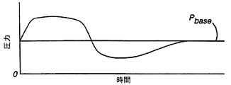
これに関連して、図5Bは、単一の呼吸サイクル上で従来の連続的気道正圧(CPAP)及び2レベルの気道正圧(PAP)装置と比較して気道比例正圧(PPAP)装置10によって発生する圧力出力曲線を示す。時点48(ピーク吸気流)、時点50(呼気開始)及び時点52(呼気終端)で適切な吸気副木圧力及び呼気副木圧力を印加する限り、通常従来の連続的気道正圧(CPAP)又は2レベルの気道正圧(PAP)療法によって供給される圧力より低い圧力が呼吸サイクルの間の別の全時間で供給される。図5Bの「気道比例正圧(PPAP)」曲線によりこの減少する出力圧力を表す。図5Bのハッチング領域は、典型的な呼吸サイクルの間に、2レベルの気道正圧(PAP)の気道比例正圧(PPAP)、気道吸気正圧(IPAP)及び呼気状態気道圧力(EPAP)段階により印加される圧力の相違を反映する。ハッチング領域は、気道比例正圧(PPAP)に起因する呼吸動作又は動作軽減を概念化して示す。期待されるように、気道比例正圧(PPAP)により補助される被験者に対して動作軽減により大きな安心感が与えられ、呼吸治療に対する協力が増加する。従って、本発明では、気道比例正圧(PPAP)療法は、被験者の安心感(及び治療への協力)が連続的気道正圧(CPAP)又は2レベルの気道正圧(PAP)療法により与えられる治療を上回る新規な呼吸不全治療を行うことができる。
【0053】
再び図1に関連して、気道比例正圧(PPAP)回路28からの指令信号54に応答して圧力コントローラ24は連続的に制御され、可変圧力を出力する。次に、指令信号54は、流れ変換器22、漏洩検出システム32、基礎圧力制御装置42、吸気利得設定制御装置44、呼気利得設定制御装置46及び他の実施の形態で使用する圧力変動制御装置56からの出力の1つ又はそれ以上の影響を受けて形成され、圧力変動制御装置56は後述する。
【0054】
通常の呼吸では、流れが開始する前に、負の気圧勾配を発生しなければならない。従って、気道に発生する負圧波形は、吸気作用の開始時に先行して、吸気流を誘発しなければならない。例えば睡眠無呼吸症候群(OSAS)に特有な不安定な気道では、適切な補償手段によって適応できない場合、負圧勾配及び吸気流開始の非同期関係により、気道内の負圧を克服するのに充分な圧力(低い流れのため)を気道比例正圧(PPAP)療法が生成しない状況になり、全体的又は部分的な気道崩壊が発生することがある。多くの方法によりこの課題を解決することができる。例えば、より高い気道比例正圧(PPAP)基礎圧力を使用して、追加の圧力により吸気作用の開始時に気道を支えることができる。別法として、図6A及び図6Bに示すように、気道比例正圧(PPAP)方法を駆動する充分な流れが発生するまで、吸気作用の開始時に一時的に圧力を増加して気道を支持することが可能である。本発明では、吸気作用の所期段階の間に圧力を加えて、吸気流の増加に伴い圧力が気道を支えるいくつかの現実的な方法を提供する。
【0055】
気道比例正圧(PPAP)回路28に作動接続された圧力変動制御装置56を使用して、一時的に圧力を増加し、吸気作用の初期段階に所望の高圧力波形を選択することができる。これに関連して、吸気作用の発端で出力される圧力に対して最小値として圧力変動を使用して、吸気作用の間に利用できる出力に対する下記の代替式を与えることができる。
【0056】
Pinhalation = 下記の大きい方
Pbase + GainInsp *流れ
又は
Pbase + Pprofile
但し、「Pinhalation」は吸気作用の間に被験者の界面材に供給される圧力、「Pbase」は、基礎ライン圧力(概念的に呼気状態気道圧力(EPAP)に等しい)、「流れ」は、見積もられた被験者に対する気体流、「GainInsp」は、流量に基づいて圧力を増加するために吸気作用(正流れ)の間に使用する定数、「Pprofile」は、吸気作用の開始時に気道を支えるために圧力変動を発生する関数である。この種の圧力変動機能は、タイムベース(例えば図6Bの点線60で示す後方傾斜変化)の例えば図6Bの点線58で示す段階変化又は他の機能的形状のように連続的でよい。
【0057】
別法として、吸気作用の所定の初期部分に対する出力圧力を制御するためのみに圧力変動を使用することができる。下式は、この種の制御条件で吸気作用の間のシステム出力圧力を示す。
【0058】
Pinhalation = Pprofile呼吸開始からXまで
及び
Pinhalation = Pbase + GainInsp * 流れ Xから呼気開始まで
但し、「Pinhalation」は、吸気作用の間に被験者の界面材に供給される圧力、「Pbase」は、基礎ライン圧力(概念的に呼気状態気道圧力(EPAP)に等しい)、「流れ」は、見積もられた被験者の気体流、「GainInsp」は、流量に基づいて圧力を増加するために吸気作用(正流れ)の間に使用される定数、「Pprofile」は吸気作用の開始時に気道を支える圧力変動を生成するいかなる関数である。この種の関数は、例えば後方に傾斜する変化のような段階変化又はタイムベースのように連続的な形状又は他の機能的形状でよい。「X」は、時間又は曲率、ピーク流量からの低下百分率、積分、導関数、従来の呼吸分析又は流量分析と時間との組合せのように流れ信号の解析により決定される予め選択された転移点である。
【0059】
気道比例正圧(PPAP)装置10は、周期的容積、吸気時間、呼気時間、ピーク圧力、ピーク流量、O2飽和値(外部電源から入力される電圧として)、複数の圧力の1つ(外部電源から入力される電圧として)、面体圧力、推定される漏洩及び例えばPbase、Auto GainInsp、GainInsp、GainEsp、気道吸気正圧(IPAP)及び呼気状態気道圧力(EPAP)等のシステム要因等の要因を測定しかつ記憶装置62の(図1)内に記憶する性能を有する。このリストは限定的でなく、他の要因も記憶装置62に記憶させることができる。
【0060】
被験者に変更を要する課題を解決する本発明のシステムの方法は、気道比例正圧(PPAP)の有益な特徴を図7A及び図7Bに示す連続的気道正圧(CPAP)のような制御された療法に組み合わせることにある。
【0061】
連続的気道正圧(CPAP)では、単一の圧力が発生して、全睡眠時間中に供給される。気道比例正圧(PPAP)を連続的気道正圧(CPAP)と好適に連結して呼気の間に、被験者に供給される圧力を低下することができる。結合された気道比例正圧(PPAP)と連続的気道正圧(CPAP)の下に供給される圧力に対して下式が得られる:
Pinhalation = CPAP(連続的気道正圧)
及び
Pexhalation = CPAP(連続的気道正圧)+ GainExp *流れ
但し、「GainExp」は、流量に基づいて圧力を減少するために呼気(負流れ)の間に使用される定数である。
【0062】
図8A及び図8Bは、種々の方法で気道比例正圧(PPAP)を2レベルの気道正圧(PAP)療法と組み合わせて効果的な治療の圧力波形を形成できることを示す。前記気道比例正圧(PPAP)と連続的気道正圧(CPAP)との構成とほぼ同様であるが、適用例の1つは、呼気の間に圧力を低下する気道比例正圧(PPAP)を使用することである。合成気道比例正圧(PPAP)と2レベル気道正圧(PAP)との合成圧力を供給する式を下記に示す:
Pinhalation = IPAP(気道吸気正圧)
及び
Pexhalation = EPAP(呼気状態気道圧力)+ GainExp * 流れ
但し、「GainExp」は、流量に基づいて圧力を減少するために呼気(負流れ)の間に使用される定数である。
【0063】
気道比例正圧(PPAP)を2レベルの療法に合併する他の方法は、図9A及び図9Bに示すように、吸気サイクルの第1の部分に対して被験者に気道吸気正圧(IPAP)を適用し、呼吸サイクルの残部に気道比例正圧(PPAP)を適用するものである。気道吸気正圧(IPAP)及び流量に基づき各呼吸に対して、GainInspは下式により自動的に算出される:
Pinhalation(t0〜tl)= IPAP(気道吸気正圧)
Pinhalation(tl〜t2)= Pbase + AutoGainInsp * 流れ
及び
Pexhalation = Pbase + GainExp * 流れ
但し、「流れ」は、推定された流量、「t0」は、呼吸開始時点、「t1」は、推定された流量が吸気ピーク流量の所定の百分率であるときの時点、「t2」は、呼気開始時点、「IPAP」は、連続的に印加される気道吸気正圧、「Pinhalation(t0〜tl)」は、時点t0からt1まで被験者に供給される圧力、「Pbase」は、連続的基礎圧力、「AutoGainInsp」は、時点t1での(IPAP-Pbase)/流れに等しい、「Pinhalation(tl〜t2)」は、時点t1からt2まで被験者に供給される圧力、「GainExp」は、被験者に供給される圧力を減少するために呼気の間に使用される定数、「Pexhalation」は、呼気の間に被験者に供給される圧力である。
【0064】
図3A〜図9Bに示す流量出力曲線及び気道比例正圧(PPAP)圧力出力曲線は単一の呼吸サイクルの吸気段階と呼気段階の間に装置が出力する圧力及び流量を示す。気道比例正圧(PPAP)曲線及び流量曲線は、勿論、下記のように、特に充分に自動化された気道比例正圧(PPAP)療法の下に、被験者の呼吸条件に従い呼吸サイクルから呼吸サイクルまで幾分変化すると思われる。更に、特に睡眠無呼吸症候群(OSAS)治療の間に、拡張治療期間の異なる段階に関連する呼吸サイクルの間に、幾分より大きいバリエーションが発生することもある。
【0065】
図2は、本発明による気道比例正圧(PPAP)装置10’の別の好適な実施の形態を表す。加算気道吸気正圧(IPAP)/呼気状態気道圧力(EPAP)(2レベルの気道比例正圧(PPAP))回路64を除き、気道比例正圧(PPAP)装置10’は、気道比例正圧(PPAP)装置10に対して構造及び機能の点で同一である。この実施の形態では、流れ変換器22からの出力66は、2レベルの気道正圧(PAP)回路64に供給される。2レベルの気道正圧(PAP)回路64は、例えば米国特許第5,148,802号、第5,433,193号及び第5,632,269号に開示された、従来の回路を使用でき、前記特許の内容を本明細書に引用する。2レベルの気道比例正圧(PPAP)回路64からの出力68は、気道比例正圧(PPAP)回路28に送られる。被験者が肺まで息を吸い込んでいる場合、出力68は気道吸気正圧(IPAP)信号から成り、被験者が息を吐き出している場合、出力68は、呼気状態気道圧力(EPAP)から成る。気道比例正圧(PPAP)回路28の論理は、気道比例正圧(PPAP)-2レベル療法の前記組合せのうちの予め選択された一つに従ってこの入力を利用して、所望の圧力指令信号54を発生する。
【0066】
本発明では、基礎圧力、流量及び利得(及び使用すれば圧力変動)により被験者に供給する圧力を決定する。所与の被験者条件のに対し、気道の安定化に必要なように、これらの設定を調整することができる。睡眠無呼吸症候群(OSAS)では、被験者の周期的な条件、即ち最低限度で瞬間的な条件は睡眠状態及び体調によって変化する。従って、睡眠期間の一部の間に設定は充分良好に機能しても、設定は異なる時間には同様には機能しない。換言すれば、最も不安定な状態で気道を支える設定によって、より安定した時間の間に必要なレベルより圧力を上昇することができる。同様に、その期間中の1時点で良好に機能する設定は他の時点では不十分かもしれない。
【0067】
本発明は、気道比例正圧(PPAP)療法の最適化に必要な被験者の変化による影響を最小にするいくつかの方法を提案する。その一つの方法は、利得、圧力変動及び基線圧力を自動的に調整して被験者の要求に合致させることである。この調整は、例えば大きさ、形、導関数、積分(容積)、圧力、鼾、動脈の酸素飽和度、吐出されるCO2、気道直径又は他の要因等の流れに関する被験者パラメータの分析値に基づいて行うことができる。
【0068】
前記要因(パラメータ)の一つ又はそれ以上を使用して、システムのGainInspを調整し、部分的な気道の呼吸低下を防止することができる。このシステムの目標は、以下の被験者条件のいずれにでも応答するGainInspを増加することにある:
°吸気流の減少;
°吸気容積の減少;
°流れ又は圧力信号分析により定まる気道抵抗の増加;
°圧力又は音の変化により示される気道不安定性;
°動脈中の酸素飽和度の低下;又は
°気道直径の減少
【0069】
また、本発明による装置では、これらの条件が存在しない場合、最小のGainInspを維持することができる。
また、現在のシステムでは、基礎圧力(Pbase)を調整して、気道(呼吸停止)の完全な崩壊又は危険な圧潰(危険な呼吸低下)を防止することができる。流れ信号の分析及び/又は反射圧力波又は圧力及び流量の組合せにより呼吸停止を検出して、気道開通を決定することができる。更に、気道圧潰又は呼吸運動の欠陥の何れによって呼吸停止が発生したのかを決定することが重要な場合もある。妨害事由を検出した場合、基礎圧力を増加して、気道を開くことができる。本発明のシステムの別の性能は、前記の条件が存在しない場合に、最小のPbaseを維持することである。
【0070】
また、本発明のシステムでは、圧力変動(Pprofile)を調整して吸気作用の開始時に呼吸停止又は呼吸低下を防止することができる。このように、本発明のシステムでは、気道抵抗の増大、気道不安定性を示す圧力変動若しくは音の変化、動脈内の酸素飽和度の低下、気道直径の減少又は吐出されるCO2の変化等を示す吸気流の減少、呼吸容量の減少、流れ波形分析に応答してPprofileを増加することができる。本発明は、前記の条件が存在しない場合、最小圧力変動を維持する機能がある。
【0071】
図10は、本発明により構築された充分に自動化された気道比例正圧(PPAP)装置10''の好適な本実施の形態を示す。図1の気道比例正圧(PPAP)装置の構造及び機能とほぼ同様に、気道比例正圧(PPAP)装置10''は、マイクロプロセッサ又は中央制御ユニット70を備え、中央制御ユニット70は、連続的帰還信号として流れ変換器28からの出力信号72を利用して、Pbase、Pprofile、GainInsp及びGainExpを必要に応じて連続的に調節することができる。しかしながら、中央制御ユニット70は、呼吸気体流れに関連する又は関連しない前記被験者要因の何れかに応答して、連続的なシステム制御機能を行うように構成できる。
【0072】
また、比例気道正圧装置10''は、所定帰還の間にピーク流れ及び/又は周期的容積が減少することにより呼吸低下を検出し、所定期間の間に非常に流量が減少することにより呼吸停止の発生を検出する性能がある。例えば、呼吸低下を検出するために、吸気ピーク流量又は周期的容積の短期平均(例えば3息平均)と、ピーク流量又は周期的容積(の長期平均例えば、20息以上)とを比較するように中央制御ユニット70をプログラム制御することができる。25%を超える減少値を検出する場合、システムは呼吸低下の存在を決定する。漏洩量が正しく推定されかつ安定する場合にのみ、この判定は好適に行われる。従って、漏洩量の大きい変更又は漏洩回復の初期のデータは無視される。
【0073】
本発明は、呼吸停止の間に、気道が開放(中心呼吸停止)しているか又は遮断(遮断性呼吸停止)しているかを決定する方法を更に含む。長時間の呼吸停止を一度検出すると、システムは、中央制御ユニット70の指令に従ってGainInspを2cmH2Oだけ自動的に増加し、約1秒間待ってから圧力を初期の値に減少させる。この圧力変化の間に、流れの重大な変化が発生する場合に、システムは気道が開いている(中心呼吸停止)と判断する。流れの重大な変化が発生しない場合、システムは気道が遮断されている(閉鎖性呼吸停止)と判断する。システムは、周期的な間隔で全期間の間各呼吸停止を連続的に監視して、呼吸停止の本質を決定する。
【0074】
好適な実施の形態では、気道比例正圧(PPAP)装置10の制御は下記のように自動的に調整される。呼吸低下のとき、2cm/リットル/秒だけGainInspを増加する。閉鎖性呼吸停止のとき、1cmH2OだけPbaseを増加する。長時間閉鎖性呼吸停止を検出する限り、装置はPbaseを増加し続ける。必要に応じて5息が経過するまで、装置は再びGainInspを増加しない。30息の期間を超えて呼吸低下又は呼吸停止が起こらない場合、GainInspは1cm/リットル/秒だけ減少する。50息の期間を超えて呼吸低下又は呼吸停止が起こらない場合、Pbaseは1cmH2Oだけ減少する。更に、必要又は所望に応じて、被験者の呼吸気体の流れがゼロより大きい間、装置は、O2の供給を制御できる。
【0075】
図示しないが、本発明の更なる実施の形態では、充分に自動化された気道比例正圧(PPAP)と、連続的気道正圧(CPAP)及び/又は2レベルの気道正圧(PAP)療法とを組み合わせることができる。これらの場合に、充分に自動化された気道比例正圧(PPAP)システム内のGainInspを制御する同一の論理を使用することにより、連続的気道正圧(CPAP)又は気道吸気正圧(IPAP)を制御することができる。同様に、充分に自動化された気道比例正圧(PPAP)について説明した方法に類似する方法でPbaseを制御することができる。
【0076】
充分に自動化された気道比例正圧(PPAP)-連続的気道正圧(CPAP)又は気道比例正圧(PPAP)-2レベル気道正圧(PAP)システムにより、Pprofileを調整して、吸気作用の開始時の呼吸停止又は呼吸低下を防止することができる。従って、この種のシステムでは、以下の被験者の条件のいずれかに直面しても、連続的気道正圧(CPAP)(又は気道吸気正圧(IPAP))又はPprofileを増加することができる:
°吸気流の減少;
°吸息性の容積の減少;
°流量信号分析又は圧力信号分析により決定される気道抵抗の増加;
°圧力変化又は音変化により示される気道不安定性;
°動脈中の酸素飽和度の低下;
°気道直径の減少。
【0077】
前記の条件が存在しないとき、連続的気道正圧(CPAP)又は気道吸気正圧(IPAP)は最小レベルに維持される。
【0078】
従って、気道比例正圧(PPAP)療法を使用すれば、呼気流量に応答して気道比例正圧(PPAP)を加えて使用することにより、睡眠無呼吸症候群(OSAS)の治療で呼気の間に圧力をPbaseより低く減少する前記の方法と同様に、呼気段階の全終端を通じて被験者の呼気終端圧力(PEEP)レベルより少ないレベルに呼気の間に印加される圧力を減少することができる。このように、呼気段階で印加される圧力を呼気終端圧力(PEEP)より低く減少させることにより、呼気状態気道圧力(EPAP)の間に印加される一定の呼気段階圧力と比較して呼吸動作を減らして、被験者の快適さを増進することができる。実際に、呼気終端圧力(PEEP)を使用するいかなる換気モードにも気道比例正圧(PPAP)を適合させることができる。この適用例は、呼気終端圧力(PEEP)による圧力保持、呼気終端圧力(PEEP)による比例援助換気(PAV)又は呼吸援助療法での呼気終端圧力(PEEP)の他の応用法を含むことができる。
【0079】
更に、吸気段階では、気道比例正圧(PPAP)療法により酸素を容易に管理して、補足的な酸素を必要とする慢性閉塞性肺疾患(COPD)被験者を治療することができる。
【0080】
本発明は、時間に対して変化させて被験者に供給するガスの圧力を制御することができる。例えば、本発明の一実施の形態では、全期間にわたり第1の最小圧力から所望の療法圧力まで被験者に供給する圧力を増加することができる。この傾斜圧力増加により、時間中に療法圧力まで増加される比較的低い圧力の下に被験者に熟睡する時間を与えることができる。その後、圧力は増加して、被験者が眠た後に治療圧力が印加される。朝には逆の過程を実行することができ、被験者が起床しようとする直前に圧力は治療圧力から減少される。図10に示す傾斜制御装置120は、気道比例正圧(PPAP)回路28に指令信号を付与し、傾斜サイクルに従って圧力を供給する手動動作コントローラを略示する。また、中央制御ユニット70の出力により傾斜制御装置120を調整することができる。傾斜制御装置120を使用して、圧力傾斜期間、傾斜圧力開始時間、傾斜圧力終了時間、圧力傾斜形状等の圧力傾斜関数(圧力傾斜作用)に関連して要因(パラメータ)を設定することができる。
【0081】
被験者の圧力を制御する他の方法のみならず、一つ又はそれ以上の圧力傾斜作用により被験者に供給される圧力レベルを制御する技術の例は、本願明細書の一部として参照される米国特許第5,492,114号及び第5,551,418号並びに米国再発行特許第RE35,295号に開示される。これらの米国特許に開示された多くの技術を本発明の装置及び方法に組み合わせて、被験者の治療に必要な最適な療法を提供することができる。
【0082】
本発明の更に別の実施の形態では、気道比例正圧(PPAP)回路28及び/又は中央制御ユニット70に警報装置122が接続される。様々な状況の結果を報知するように、警報装置122を制御して作動することができる。しかしながら、本発明の好適な実施の形態では、自動的に決定される利得が所定範囲外の値に該当することに対応して、警報装置122を作動することができる。
【0083】
本発明では、前記AutoGainInspのように自動的に決定される利得に対する値を限定することにより、例えば、被験者に供給される過度に高い圧力となり限界を超過するような、自動的に決定される利得が所定の限界値を超えることを防止することができる。所定の期間にわたり前記限界値を変更して、利得自体を変更することもできる。また、所定の期間にわたり自動的に決定される利得内で実施できる変更値も変更制御して、所定の期間にわたりかつ所定の値を超えて自動的に決定される利得が変化することを防止することができる。
【0084】
鬱血性心不全(CHF)の治療に気道比例正圧(PPAP)を使用する場合に、本発明は、心臓に休止の同じレベルを供給しながら、中間圧力及び呼気動作を減少する。心臓の前負荷及び後負荷(好ましくは5〜10cm H2Oの範囲で)の減少に必要な圧力にほぼ等しい正の基礎圧力を印加することにより、本発明は心臓の負担を軽減する。呼吸動作に比例する吸気作用間の追加的正圧により、被験者は吸気作用の間に発生する負圧作用を克服することができる。典型的な鬱血性心不全(CHF)の被験者は正常な順応性を有する点で、気道比例正圧(PPAP)は特に鬱血性心不全(CHF)の被験者に適合する。前記被験者では、呼吸負荷の多くを流れ信号から推定することができる。呼気の間に圧力を基礎圧力より低く減少することにより、被験者は、心臓に対する利点を低減させずに、呼気動作を減少することができる。呼吸動作が減少して平均圧力が低下しても、正味効果による心臓に対する利益は同一である。
【0085】
気道圧潰を防ぐ気道比例正圧(PPAP)療法の使用と同様に、鬱血性心不全(CHF)を治療する気道比例正圧(PPAP)療法は、心臓の前負荷及び後負荷の減少に必要な圧力の最小量のみを供給する。これにより、呼吸負荷の存在せずに、心臓の前負荷及び後負荷の減少に必要な圧力に等しい基礎圧力を心臓の外部に適用すると共に、呼吸動作を最小化しながら、心臓の前負荷及び後負荷に対する呼吸負荷の影響を克服するのに必要な変化する圧力を供給することができる。
【0086】
呼吸系を介して心臓の外部に正圧を供給することは、2つの利点があり、第1に、鬱血性心不全(CHF)被験者の肥大した心臓を正圧により正常に近いサイズに減少する。正常サイズへの復帰により、心臓の筋肉をより効率的に作動させることができる。第2に、胸腔内の正圧により、心臓が身体の他の部分に血液を圧送するのに打ち勝つ圧力量を低減する。
【0087】
心臓及び胸腔は、同じ圧力である。一般的に、この圧力は、呼吸負荷の影響のために周囲圧力を中心に変動する。循環システムは、心臓のポンプ作用により変化するが、通常の緊張作用のある被験者では平均100mmHgの動作圧力を有する。心臓は、胸腔から加圧血液循環システムに血液を圧送する力を発揮しなければならない。胸腔内の圧力を増加することにより、心臓が血液を圧送しなければならない圧力量を減少することができる。10cmH2O又はほぼ10mmHgである胸腔内の圧力により、10mmHg/100mmHg又はほぼ10%だけ心臓の負担を軽減することができる。
【0088】
心臓に対する呼吸作用の影響は、次の通りである:吸気作用の間に、胸(心臓を包囲する)の圧力は、身体の他の部分に対してより負になる。この増加する負圧により、心臓が胸腔から身体に血液を圧送するために発生する圧力量を増加する。吸気作用の間に基礎圧力を超える圧力を供給することにより、気道比例正圧(PPAP)は胸腔圧力の減少を補い相殺して、胸部内の圧力を比較的一定に維持することができる。
【0089】
呼気の間に胸部内の圧力は、身体の他の部分に対してより少ない負圧になる。呼気の間に圧力を減少することにより、気道比例正圧(PPAP)は胸腔内の圧力の増加を補い相殺して、胸部内の圧力を比較的一定に維持することができる。
【0090】
呼気の間に、圧力の減少を最小にして、増加する圧力を利用することにより、気道比例正圧(PPAP)の可変部分により下方基線を設定して、一定の圧力を使用し、心臓に同一の利点を与えることができる。呼気の間に基線を下げかつ圧力を低減することにより呼吸動作を軽減し、被験者の快適さを増進することができる。
【0091】
既存の連続的気道正圧(CPAP)装置について図7に示す構造と同様の気道比例正圧(PPAP)の変形例を実施することが望ましい。既存の連続的気道正圧(CPAP)装置に関する気道比例正圧(PPAP)の変形例により被験者の快適さが増進され、気道比例正圧(PPAP)モードを含む新規な連続的気道正圧(CPAP)装置を製造し、導入することに伴う重大な財政的負担又は他の負担がなく協力が得られる。連続的気道正圧(CPAP)装置で気道比例正圧(PPAP)療法を行うことは、例えば図7A及び図7Bについて説明したように、様々な方法で実行することができる。
【0092】
図7に示すように、呼気の間に減少する圧力曲線を生成するために用いる反動的な構成要素が所定の減少する圧力変動と交換した場合、より経済的な方法の連続的気道正圧(CPAP)システムに気道比例正圧(PPAP)の変形例を実施することができる。この圧力変動は、被験者が呼吸サイクルの呼気段階の間に連続的気道正圧(CPAP)装置によって異なる状態で適用される一定の連続的気道正圧(CPAP)圧力と交換される。本発明の好適な実施の形態では、所定の圧力変動は、被験者の通常の流れにほぼ符号する形状を有する。
【0093】
図11A及び図11Bは、単純化された圧力変動発生技術を利用する本発明の別の実施の形態により得られた装置圧力曲線出力を示す図7A及び図7Bに類似する流量と圧力を示すグラフである。図11Aの流れ信号80は、被験者の吸気段階82及び呼気段階84を示す。図11Bに示すように、吸気段階82の間に連続的気道正圧(CPAP)圧力86が供給される。呼気段階の間、圧力サポート装置が制御され、所定の圧力変動88に続く減少圧力が供給される。結合された連続的気道正圧(CPAP)と気道比例正圧(PPAP)との下に供給される圧力に対する式は、次の通りである:
Pinhalation = CPAP(連続的気道正圧)
Pexhalation = CPAP(連続的気道正圧)−(所定の圧力変動)。
【0094】
連続的気道正圧(CPAP)圧力を減少するのに使用される所定の圧力変動は、主に呼吸治療専門家により0〜4cmH2Oの範囲内で選択される大きさMと、図7Bの圧力曲線とは異なり、被験者の瞬間的な流量又は容積に基づいて直接決定されない持続時間Dとを有する。大きさMは、一定の連続的気道正圧(CPAP)値からの圧力降下を示す。持続時間Dの値は、被験者の平均呼気期間の分数であることが好ましい。
【0095】
異なる大きさ、持続時間又はこれらの両方を有する多数の所定の圧力変動を連続的気道正圧(CPAP)/気道比例正圧(PPAP)装置に記憶させて被験者に供給することができる。図11Bは、それぞれ大きさM1、M2及びM3及び持続時間D1、D2及びD3を有する3つの予め定められた圧力変動P1、P2及びP3を示す。本発明の好適な実施の形態では、呼気の間に、被験者に供給される圧力は、例えば図3A及び図3Bに示すように、流量又は容積に基づく気道比例正圧(PPAP)から発生する圧力変動にほぼ符号するように圧力変動が選択される。図11Bに示すように、圧力は、呼気の開始時に急激に低下し、その後基線の連続的気道正圧(CPAP)に向かって徐々に上昇する。
【0096】
連続的気道正圧(CPAP)/気道比例正圧(PPAP)装置のこの実施の形態は、気道比例正圧(PPAP)装置及び前記の技術の場合のように、被験者からの流量信号又は圧力信号に基づいて被験者に供給される流量及び/又は圧力を制御せず、単に開始時又は吸気作用及び/又は呼気作用を検出するに過ぎないので、この実施の形態に必要なセンサは前記実施の形態程、正確である必要はない。例えば、呼気状態及び呼気状態を決定するのに高価な呼吸流量計をサーミスタ又は熱電対に交換することができる。また、速度制御型モータを使用して呼気段階の間に被験者に供給される圧力変動を発生して、圧力制御弁を省略できる。
【0097】
所定の圧力変動を使用して、呼気の間に連続的気道正圧(CPAP)を減少する実施の形態について説明したが、同一の技術を2レベルの圧力支援装置に適用して、例えば、所定の圧力変動により2レベルの呼気状態気道圧力(EPAP)を減少して、図8Bに示す圧力曲線を形成することができる。
【0098】
気道比例正圧(PPAP)を実行して、例えば2〜3cm/リットル/秒の範囲を越えるある値を超えて利得を設定する場合に、装置により発生する圧力が不安定になる傾向のあることが判明した。即ち、図12に示すように、被験者の呼気段階94の間に被験者に加えられる圧力波形92内に振動90が発生する。これらの振動は、呼気段階の開始に続く最初の圧力低下の後に発生するのが通例であり、被験者の気体流の相互作用及び及び得られる圧力減少の結果として発生すると思われる。
【0099】
この振動が発生する可能性があるにも係わらず、呼気段階の残り時間の間に、極力円滑な圧力変動を維持しながら、呼気の開始時に被験者に供給される圧力を比較的大きく減少することが望ましい。本発明の一実施の形態では、下式に従って呼気の間に被験者に圧力を供給することによってこれを達成できる:
Pexhalation = 下記のより大きい方:
Pbase -(GainExp *流れ)
又は
現在の圧力、
但し、「現在の圧力」は、呼気段階の間のその時点で被験者に供給される圧力である。
【0100】
図13は、前記技術を使用して呼気段階の間に発生する振動を除去する点を除き、図12に示す圧力変動92に類似する圧力変動92'を示す。例えば、圧力振動のために直前の圧力から圧力が減少し始める時点96では、算出圧力、即ち、Pbase−GainExp *流れが現在の圧力より小さいその後の全ての時点での圧力、即ち現在の圧力を置き換えることにより、上記の技術はこの減少を防止し、これにより、算出圧力が現在の圧力より大きくなる時点100まで現在の圧力、即ち時点96の圧力に符号する安定領域98を形成する。
【0101】
被験者に供給される圧力が常に現在の圧力及び算出圧力の中で確実により大きいものであることによって、呼気の間に被験者が受ける圧力は振動しない。被験者に供給すべき圧力が現在の圧力より低く減少し始める場合、装置は算出圧力を使用せずに、被験者に現在の圧力を供給し続けることにより、現在の圧力より低い圧力減少を防止する。
【0102】
本発明による第2の実施の形態では、呼気段階の間に被験者に供給される圧力を決定する完全に異なる算出法を使用して、圧力振動を回避することができる。前記実施の形態のように、手動又は自動のいずれかで選択された利得により操作される被験者の流れに基づいて、被験者に供給される圧力の算出基礎を形成する代わりに、被験者に供給すべき圧力は、吐出すべき量として示すように、肺にまだ含まれる気体量に基づいて算出される。吐出すべき量は、被験者内の現在の気体容積と、安静状態の被験者内の気体容積との差異に相当する。肺内の気体容積は、現在流れ信号から容易に推定できる。安静状態の被験者内の気体容積は、従来の技術を使用して決定されて、周期的に更新して確実に算出精度を向上することができる。
【0103】
本実施の形態では、気道比例正圧(PPAP)装置による少なくとも呼気段階の間の圧力出力は、気道比例正圧(PPAP)回路にコード化できる下式で表される:
Pexhalation = Pbase −(Volumeto be exhaled * GainExp)
但し、「Pbase」は、基礎ライン圧力(ゼロ以上で概念的に呼気状態気道圧力(EPAP)に等しい)、「Volumeto be exhaled」は、被験者内の現在の気体容積から安静状態の被験者の気体容積を引いた差、「GainExp」は圧力の減少のために呼気(負流れ)の間に使用される定数である。
【0104】
吸気段階の間の圧力出力は、前記技術を使用して決定される。図14は、上式を使用して被験者に供給すべき圧力を決定した圧力曲線102を示す。図14から明らかなように、圧力曲線102は、呼気の間に圧力を低下し、呼気段階の終端で圧力を基線に戻し気道圧潰を防ぐ機能を達成する。
【0105】
吐出すべき気体容量(Volumeto be exhaled)は、呼気段階の開始時に比較的大きいので、呼気段階の初期の圧力低下は非常に大きくなる。被験者に供給すべき圧力の算出に減衰要因を追加することにより、呼気段階の初期の大きな圧力降下を平滑化することが好ましい。
【0106】
呼気段階の開始時に初期圧力降下を減衰させるのに使用できる多くの技術がある。しかしながら、本発明の好適な実施の形態では、呼気段階の間に被験者に供給される圧力は、下式で表される:
呼気段階の開始(t0)からXまで:
【式1】
![]()
Pexhalation = Pbase -(Volumeto be exhaled * GainExp)
但し、「t」は、呼気段階の開始に続く現在の時間、「X」は、時間又は例えば曲率、ピーク流量からの降下百分率、積分値、導関数、事前の呼吸分析若しくは流れ分析と時間との組合せ等の流れ信号の分析により決定される呼気段階の開始後に予め定められた転移点である。
【0107】
図14に示すように、減衰計数(減衰要因)t/Xを考慮して、t0からXまでの初期期間中に被験者に供給される圧力を算出することにより、呼気の開始時の圧力降下を減少するようにX値が選択される。その後、減衰要因を考慮せず、上記2式中第2式に従って被験者に印加すべき呼気圧力を算出する。従って、本発明の本実施の形態では、呼気の開始時の初期圧力降下を確実に予想可能なパラメータの範囲内に維持しながら、全呼気段階にわたり圧力曲線が円滑になる。
【0108】
本実施の形態では、呼気段階の開始時に初期圧力降下の大きさを平滑化する他の減衰技術も使用できる。従って、本発明は、前記減衰技術に限定されない。
【0109】
本発明による最良の実施の形態を図示する目的で本発明を説明したが、前記説明は図示の目的に過ぎず、本発明は前記実施の形態に限定されず、本発明の特許請求の範囲及び本発明の精神に該当する全ての変形例及び均等な装置を含む。
【図面の簡単な説明】
【図1】 本発明による装置の機能を示すブロック図
【図2】 本発明による装置の別の実施の形態の機能を示すブロック図
【図3A及び図3B】 本発明による装置が単一の呼吸サイクルの吸気段階と呼気段階の両方で、加圧された呼吸用気体を比例状態で被験者に出力する一般的な方法を視覚的に表す流量及び圧力を示すグラフ
【図4A及び図4B】 それぞれ図3A及び図3Bと同様に、本発明の比例気道正圧回路の吸気及び呼気利得設定制御部を選択的に調整することにより達成される複数の装置出力圧力曲線を例示する流量及び圧力を示すグラフ
【図5A及び図5B】 それぞれ図3A及び図3Bと同様に、従来の呼吸援助装置の圧力出力曲線と共に、本発明による装置に代表的な圧力出力曲線を対比する流量及び圧力を示すグラフ
【図6A及び図6B】 それぞれ図3A及び図3Bと同様に、吸気作用の開始を容易にするために呼吸の吸気段階の初めに使用される選択的圧力変動を表す流量及び圧力を示すグラフ
【図7A及び図7B】 それぞれ図3A及び図3Bと同様に、本発明の他の実施の形態による装置圧力出力曲線を表す流量及び圧力を示すグラフ
【図8A及び図8B】 それぞれ図3A及び図3Bと同様に、従来の2レベルの気道正圧治療を本発明による比例気道正圧治療に組み合わせることによって得られる装置圧力出力曲線を表す流量及び圧力を示す線図
【図9A及び図9B】 それぞれ図3A及び図3Bと同様に、従来の2レベルの気道正圧治療を本発明による比例気道正圧治療と組み合わせることによって更に得られる装置圧力出力曲線を示す流量及び圧力を示すグラフ
【図10】 本発明による装置の更なる実施の形態を示すブロック図
【図11A及び図11B】 それぞれ図7A及び図7Bと同様に、簡略化された圧力変動技術を利用する本発明の他の実施の形態により得られる装置圧力出力曲線を示す流れ及び圧力を示すグラフ
【図12】 呼気の間に被験者に供給される圧力振動を示すグラフ
【図13】 図12に示す振動を減少する第1の技術による圧力を示すグラフ
【図14】 図12に示す振動を減少する第2の技術による圧力を示すグラフ
【符号の説明】
14・・気流発生器、 24・・圧力コントローラ、 22・・流れ変換器、 28・・気道比例正圧回路、 32・・漏洩検出装置、 38・・最大圧力設定制御装置、 40・・最小圧力設定制御装置、 42・・基礎圧力制御装置、 44・・吸気利得設定制御装置、 46・・呼気利得設定制御装置、 56・・圧力変動制御装置、 62・・記憶装置、[0001]
Cross-reference to related applications
This application is a patent application filed on June 15, 1994 as part of a continuation-in-part of U.S. Pat. No. 5,535,738, filed on June 3, 1994. This is a continuation-in-part application No. 08/679898.
[0002]
BACKGROUND OF THE INVENTION
1. Technical field
The present invention relates to a method and apparatus for treating respiratory and / or cardiac disease, in particular for treating obstructive sleep apnea syndrome, chronic obstructive pulmonary disease, congestive heart failure and other respiratory and / or respiratory diseases. And a method and apparatus for supplying respiratory gas pressure to a subject's (patient) airway during at least a portion of a respiratory cycle.
[0003]
2. Explanation of related technology
During obstructive sleep apnea syndrome (OSAS), the airway tends to become stenotic and / or collapsed (collapsed) while the subject sleeps. Continuous positive airway pressure (continuous positive airway pressure (CPAP)) therapy has a splint function that avoids stenosis by supplying pressure that forces the airway to open. With continuous positive airway pressure (CPAP), the airway opening pressure is optimized and kept constant enough to prevent airway constriction during sleep studies. Providing a constant forced airway opening pressure, or Continuous Positive Airway Pressure-CPAP, is a simple solution to the problem posed by collapsed airways. However, this solution must provide the subject with a higher pressure than is necessary to support airway opening for most respiratory cycles.
[0004]
During inspiration, the pressure created in the lungs is lower than the pressure at the nose. This pressure difference creates an air flow to the lungs. This pressure difference creates a pressure gradient in the airway that connects the lungs and nose. That is, the subject's lungs and airways are below atmospheric pressure (ambient pressure) or negative pressure, while the nose is usually at atmospheric pressure (ambient pressure). This negative pressure acts on the airway and collapses the airway. Eliminates low ambient pressure generated by inspiration and raises the pressure level of the entire respiratory system to a level necessary to overcome any mechanical crushing force resulting from airway tissue structure, muscle tension and physical condition As such, a continuous positive airway pressure (CPAP) level is set. The suction pressure of the two-level airway positive pressure system, that is, the airway positive pressure (IPAP-Inspiratory Positive Airway Pressure) is set in a similar manner.
[0005]
During expiration, there is a positive pressure gradient between the inside of the lungs and the outside of the body. During expiration, the airway is kept open by the positive pressure gradient. At the end of expiration, the air pressure gradient is almost essentially zero and the flow of breathing gas is likewise zero, so the airway is not affected by the respiratory action. At the end of expiration, any collapse of the airway is a function of airway tissue structure, muscle tension and physical condition. The two level device attempts to provide the exhalation pressure necessary to support the airway at the end of exhalation.
[0006]
It should be noted that the pressure gradient between a pair of lungs and the outside of the body is not constant during the course of the respiratory cycle. The intake pressure gradient goes from zero at the start of intake to a negative peak value, and then increases to zero at the end of the intake action. The exhalation pressure gradient goes from zero at the start of exhalation to a peak value and then returns to zero at the end of exhalation. Since the pressure gradient changes throughout the respiratory cycle, ideally the pressure required to overcome airway collapse should change throughout the respiratory cycle.
[0007]
Conventional continuous positive airway pressure (CPAP) therapy results in therapy at a single pressure level, ignoring the change in pressure conditions. Since conventional continuous positive airway pressure (CPAP) is based solely on peak pressure conditions during inspiration, which is the worst case treatment parameter, the pressure of continuous positive airway pressure (CPAP) is rather sketchy and optimal It ’s a long way from the therapy.
[0008]
Traditional two-level positive air pressure-PAP therapy, which represents the progression of continuous positive airway pressure (CPAP), utilizes different pressure conditions to lower pressure during expiration. Nevertheless, since the two levels of positive airway inspiratory pressure (IPAP) still remain constant throughout the entire inspiration phase, based on the subject's peak need encountered during the inspiratory effect, The optimal treatment cannot be performed. Also, during the two levels of therapy, the Expiratory Position Airway Pressure-EPAP remains constant and is only related to the open support request at the end of expiration.
[0009]
In addition to sleep apnea syndrome (OSAS), positive airway pressure therapy (eg, two levels of positive airway pressure therapy) is used to treat other respiratory diseases such as chronic obstructive Pulmonary Disorder-COPD. Applied. However, one of the treatment challenges associated with this mode is that it is difficult for the subject to stop inspiratory flow. This phenomenon occurs because of the difference between the pressure required to overcome the subject's respiratory resistance at the end of the inspiratory action and the applied positive airway inspiratory pressure (IPAP). Since the former pressure generally exceeds the latter pressure, "residual" airway inspiratory positive pressure (IPAP) at the end of inspiratory action results in unpleasant and potentially harmful superinflation on the subject's lungs.
[0010]
Conversely, in order to initiate inspiratory flow, subjects with chronic obstructive pulmonary disease (COPD) must reduce pressure inside the lungs to a pressure below ambient pressure at the entrance of the respiratory system. Because of a condition commonly known as “auto-expiratory end pressure”, the lung pressure of the subject is generally higher than the ambient pressure at the end of expiration. Thus, the subject's breathing muscle must perform additional actions to dilate the lungs before the air flow to the lungs occurs to reduce the lung pressure below the level of ambient pressure. Automatic end expiratory pressure must generally be handled by a resistive back pressure known as Positive End Expiratory Pressure-PEEP. The end-expiratory pressure (PEEP) is set to a level just below the subject's automatic end-expiratory pressure (Auto-PEEP), and the amount of breathing movement necessary to start inspiratory flow can be reduced.
[0011]
In conventional therapies such as pressure retention, continuous positive airway pressure (CPAP) or two-level therapy, the same throughout the entire exhalation phase, for example the exhalation airway pressure (EPAP) phase of the two-level positive airway pressure (PAP) therapy The end expiratory pressure (PEEP) can be achieved by applying a pressure of. It should be noted that expiratory airway pressure (EPAP) is not synonymous with end expiratory pressure (PEEP). Expiratory airway pressure (EPAP) indicates the constant pressure delivered to the subject throughout the exhalation, while end expiratory pressure (PEEP) indicates the positive end expiratory pressure. Obviously, end-expiratory pressure (PEEP) is only needed at the end of expiration. Thus, performing exhaled airway pressure (EPAP) throughout the exhalation cycle can maintain a satisfactory end-expiratory pressure (PEEP), but adversely affects the breathing movements that the subject must perform during exhalation. give.
[0012]
Sleep that provides a collective function of methods and devices that induce, useless, assist, and / or resist a subject's breathing movements in addition to continuous positive airway pressure (CPAP) and two levels of positive airway pressure (PAP) Other systems have been proposed for clinical research and / or therapeutic applications, including treatment of apnea syndrome (OSAS), chronic obstructive pulmonary disease (COPD) and other respiratory diseases. These systems include, for example, but are not limited to, respiratory activity of a subject, including signs representing airway disorders such as inspiratory and / or expiratory airflow, inspiratory and / or expiratory pressure, periodic volume and stuttering Some perform certain functions in response to one or more factors associated with the. Others achieve their objectives transthoracically, while others supply air directly to the subject's airways with positive or negative pressure.
[0013]
An early example of this type of device, commonly referred to as “Iron Lung”, is a publication entitled “Mechanical Assistance for Respiration in Emphysema, Results of Servo-Respirator Controlled by the Patient” (James R. Co-authored by Harrys (Doctor of Medicine) and John M. Tyler (Doctor of Medicine), published in the American Journal of Medicine, published in January 1964, Vol. 36, pp. 68-78). The iron lung proposed in the publication is based on the subject's respiratory action (i.e., iron lung is applied by removing or applying transthoracic pressure to the outer surface of the subject's body seated in a large pressurized chamber). , Applying a negative pressure during the inspiration action, and applying an ambient air pressure or a positive pressure during the exhalation action). A ventilator that works well for the day specifically controls the internal chamber pressure in response to the gas flow or volume of detected breaths that make up the subject's spontaneous breathing. In fact, the signal obtained from a strain gauge breathing curve recorder attached to the subject's chest is electrically divided into three components: one proportional to gas volume, one proportional to inspiratory flow, and one proportional to expiratory flow. The Each component is assigned to a separate gain controller. Thereafter, the component signals are recombined, and the pressure in the pressurizing chamber is controlled by an electric variable valve provided between the blower and the pressurizing chamber.
[0014]
While effective for the intended purpose, these and other iron lung devices are disliked because they are usually large in size, cumbersome to handle, expensive and limited in scope. In other words, because of its large size and high price, it is purchased and maintained almost exclusively by medical facilities such as hospitals and clinics. In addition, iron lungs are not useful for the treatment of sleep apnea syndrome (OSAS) and related diseases where reassurance and humility are crucial to the effectiveness of the subject's cooperation and treatment. This is because the negative pressure applied during the inspiratory action constitutes a factor that collapses the airway during the inspiratory phase.
[0015]
The article entitled “A device that changes the mechanical load of the respiratory system” (M Yodnes, Di Billan, Di Jung and Etch Cloaks, published in 1987 by the American Physiological Association, pages 2491 to 2499) Disclosed is a system that produces various respiratory responsiveness by loading or unloading the breathing motion of the device. The system can generate or remove a load with inspiration, expiration, or both to assist or resist the subject's spontaneous breathing movement. The system applies a continuous positive or negative pressure directly to the subject's airway, through a command signal generated by the detected respiratory gas flow, volume, applied voltage, external function or other signal source, Loading or unloading is performed.
[0016]
However, a drawback to this system is that only a single resistance gain can be selected for resistive loading or unloading. A single gain applies to the “half wave” of the respiratory cycle (inspiratory or expiratory) or the “full wave” of the respiratory cycle (both inspiratory and expiratory). In other words, a single selected gain value is used during both inspiratory and expiratory effects according to full wave respiration loading or unloading. Thus, gains that produce good results for the reduction of breathing activity during inspiratory effects may produce results that are not very desirable, for example during exhalation effects, but are even harmful. Conversely, there is a similar effect on the gain that is specifically selected to optimize the reduction of expiratory effects.
[0017]
Also, the system proposed by Yons et al. Operates as a closed sealing system. There are problems in predicting the ability to function in an open leakproof system. Thus, it is questionable whether the device is suitable for the treatment of sleep apnea syndrome (OSAS), and which device contains some known and unavoidable unknown system leaks.
[0018]
U.S. Pat. No. 5,107,830 in the name of Ions essentially repeats all of the "respiratory assistance" (unloading) disclosed in the publication published by the American Physiological Association. However, in the system disclosed in US Pat. No. 5,107,830, the pressure output is set to zero during exhalation, so that an adjustable pressure increase can be achieved only during inspiration. Also, the output pressure is calculated as a function of both the detected subject's inspiratory flow rate and inspiratory volume. In addition, the system is applicable to chronic obstructive pulmonary disease (COPD) but not to the treatment of sleep apnea syndrome (OSAS).
[0019]
Article entitled “Mechanical load release device for respiratory trachea” (Ji Sun Poon and Susan A. Ward, published in March 1987, IEEE Biotechnology Report, Volume BME-33, No. 3, Pp. 361-365) show an apparatus that produces a function somewhat similar to one of the modes of operation described in both of the Jons publications. That is, Poon and other devices act to release the subject's respiratory load, but only during inspiration. Poon and other devices perform a respiratory assist function by establishing oral positive pressure through total inspiration at a constant rate relative to instantaneous flow. (1) Select a desired gain for the detected oral positive pressure signal, (2) Calculate the ratio of the oral pressure signal whose gain is corrected beyond the detection signal reflecting the instantaneous flow, (3) Calculation Compare the selected ratio with the selected reference ratio to generate a valve motor control signal. (4) Operate the motor that drives the servo valve using the valve motor control signal and apply it to the subject's airway By controlling the positive pressure, a certain ratio can be achieved. Thus, the output pressure of the device is determined as a function of both the detected pressure and the flow rate. In addition, this pressure must be output at a value sufficient to maintain a constant ratio of pressure to flow.
[0020]
Publication "Journal of Applied Fissiology" entitled "Servo-type Face Consists of Positive Pressure Ventilator" (Jon E. Lemers and Henry Gaucher, August 1976, Vol. 41, No. 2) Pp. 252-255) show an improved ventilator that functions as a “demand-type” mask that produces a transthoracic pressure proportional to the diaphragm exhaled breath volume. Diaphragm-derived respiratory expiratory volume represents a brain output signal to the phrenic nerve that controls the diaphragm function. The diaphragm is contracted by the breathing exhalation signal derived from the diaphragm, so that the subject can perform an inhalation operation. Diaphragm-derived respiratory expiratory volume serves as a command signal for the device and is electrically processed to produce Moving Time Average-MTA, and the subject's tracheal pressure serves as a negative feedback signal. Like the Poon et al. Device, the Remers et al. Device only assists breathing movements during inspiration.
[0021]
A device for automatically controlling the flow output and pressure output of a ventilator is disclosed in U.S. Pat. No. 3,961,627 in the name of Ernst et al. However, as with the Poon and other devices, Ernst and other devices rely on overly complex configurations based on the detected respiratory pressure and flow rate when calculating the delivered output flow and output pressure. . Specifically, Ernst and other devices measure adjacent to the subject's interface (interface material) by controlling the flow rate and pressure of the breathing gas delivered within the ventilator during the breathing cycle. We propose a technique for measuring the actual flow rate and pressure of breathing gas using a device. The measured value is converted into an electrical signal to control the flow and pressure of the breathing gas during the inspiratory and expiratory portions of the respiratory cycle through a valve located between the breathing gas source and the measuring device. . The methods for controlling the flow and pressure outputs are: (1) measure the actual flow of breathing gas adjacent to the subject, (2) measure the actual pressure of breathing gas adjacent to the subject, (3) preselect Calculate nominal values of flow and pressure from the fixed and actual values, (4) compare actual values for flow and pressure with nominal values, and (5) form a control signal to adjust the valve from this comparison. This is done by controlling the flow rate and pressure of the breathing gas.
[0022]
Apart from using the two detected respiratory factors (flow rate and pressure) and the complicated method of generating the flow rate output and pressure output of the device by iteratively processing the factors and other factors, Can deliver a basal pressure equal to the end-expiratory pressure required for ER, but Ernst and other devices require the subject to perform more than necessary for breathing, especially during the expiratory phase of the breathing cycle, It has a detrimental effect on the subject's sense of security, and the subject must continuously cooperate with the treatment.
[0023]
In addition to the treatment of respiratory failure, positive airway pressure treatment has been applied to the treatment of congestive heart failure (CHF). In using continuous positive airway pressure (CPAP) for congestive heart failure (CHF), the effect of continuous positive airway pressure (CPAP) is to increase the pressure in the thoracic cavity surrounding the heart. This has the effect of reducing the amount of pressure in the heart that pumps blood into the body. By reducing the pressure generated by the heart, the motion required for the heart is reduced. This will rest and improve the potentially sick heart.
[0024]
Further, the pressure in the thoracic cavity is affected by the breathing motion. In inspiratory action, the pressure in the chest decreases due to inspiratory activity (negative with respect to resting pressure). This forces the heart to send blood strongly into the body. In exhalation, the chest pressure increases slightly (positive for resting pressure) due to the elastic nature of the chest. This reduces the burden on the heart sending blood. Conventional continuous positive airway pressure (CPAP) can alleviate the burden on the heart, but the subject has unacceptable deficiencies because of increased expiratory activity and increased anxiety due to pressure.
[0025]
DISCLOSURE OF THE INVENTION
It is an object of the present invention to provide pressurized air to a subject's airways and can be easily adapted for the treatment of sleep apnea syndrome (OSAS), chronic obstructive pulmonary disease (COPD) and other respiratory and / or pulmonary diseases. It is to provide a simple system without the disadvantages of conventional pressurization techniques. This object can be achieved by providing a device for supplying pressurized breathing gas to the subject's airway. The device described herein as a “proportional airway positive pressure” device or “PPAP” device includes an airflow generator, a subject interface material connecting the airflow generator to the subject airway, and flowing in the subject interface material. A sensor for detecting a fluid property of the gas, a pressure controller for controlling the pressure of the breathing gas supplied to the subject, and a control unit for controlling the pressure controller.
[0026]
The controller controls the pressure controller so that at least part of the breathing cycle, the breathing gas is delivered to the subject at a minimum sufficient pressure and at any given moment at least one of the following functions: Executed: (1) Pressure required to reduce heart preload and afterload in the absence of respiratory load and necessary to overcome the effects of respiratory load during heart preload and afterload Reduce the pre-load and post-load of the heart with a pressure sufficient to be the sum of the pressure, and (2) prevent airway collapse with a pressure sufficient to prevent airway collapse. The apparatus includes a selector unit that establishes a first gain. The controller controls the pressure controller to deliver breathing gas at a minimum sufficient pressure during at least a portion of the breathing cycle based on the first gain and the detection signal from the sensor.
[0027]
The airway proportional positive pressure (PPAP) system of the present invention treats sleep apnea syndrome (OSAS) that is usually treated using conventional continuous positive airway pressure (CPAP) or two levels of positive airway pressure (PAP) therapy. In general, the airway pressure is less than the required pressure. With airway proportional positive pressure (PPAP), the subject experiences an expiratory pressure that is lower than the level of conventional two-level expiratory positive airway pressure (PAP) and well below conventional continuous positive airway pressure (CPAP). In addition, the average pressure delivered during inspiration can be lower than the conventional or two levels of positive airway pressure (PAP) airway inspiration positive pressure or continuous airway positive pressure (CPAP) level, The peak pressure of airway proportional positive pressure (PPAP) is approximately equal to the level of conventional airway inspiratory positive pressure (IPAP) or continuous airway positive pressure (CPAP). Airway proportional positive pressure (PPAP) pressure range (peak inhalation pressure for minimum exhalation pressure) is 2-20 cmH2Almost applicable between O, typical value is 8-14cmH2Within the range of O. This is 6cmH2Harmonize with two levels of positive airway pressure (PAP) therapy, where peak inspiration occurs with a minimum expiratory pressure difference of O or greater, providing sufficient comfort and responsiveness. The complexity of titration using the device of the present invention is approximately equal to the current two-level positive airway pressure (PAP) titration. Also, a fully automated airway proportional positive pressure (PPAP) can be obtained by combining a titration system with a feedback circuit.
[0028]
Similar to the treatment of sleep apnea syndrome (OSAS), use conventional two-level positive airway pressure (PAP) therapy with end expiratory pressure (PEEP) or proportional assisted ventilation (PAV) with end expiratory pressure (PEEP) ) Can be used to deliver intermediate airway pressure lower than that required to treat chronic obstructive pulmonary disease (COPD) by airway proportional positive pressure (PPAP). That is, with airway proportional positive pressure (PPAP), the average expiratory pressure lower than the conventional expiratory airway pressure (EPAP) level, the average inspiratory working pressure lower than the conventional airway inspiratory positive pressure (IPAP), The subject can receive pressure (IPAP) and a peak airway proportional positive pressure (PPAP) approximately equal to the conventional peak proportional assisted ventilation (PAV) level. Thus, respiratory motion may be less with airway proportional positive pressure (PPAP) than with conventional two-level treatment of proportional assisted ventilation (PAV) or chronic obstructive pulmonary disease (COPD) or sleep apnea syndrome (OSAS).
[0029]
It is another object of the present invention to provide a modified continuous positive airway pressure (CPAP) device that can easily detect exhalation and modify exhalation pressure to match selected pressure fluctuations. . Supplied to the subject, an airflow generator, a subject interface material connecting the airflow generator to the subject's airway, a sensor for detecting physiological conditions suitable for distinguishing between the exhalation phase and the inspiration phase of the respiratory cycle The object is achieved by providing a device including a pressure controller for controlling the pressure of the breathing gas and a control device for controlling the pressure controller. Specifically, consistent with the operation of a conventional continuous positive airway pressure (CPAP) device, a breathing gas is delivered by the controller at a first pressure level during the inspiration phase of the breathing cycle. However, during the exhalation phase of the breathing cycle, breathing gas is delivered by the controller according to a predetermined pressure variation. In this aspect, the expiratory airway pressure (EPAP) applied to the subject is reduced. Control the operation of existing continuous positive airway pressure (CPAP) devices to obtain pressure fluctuations, so you can quickly attach to many devices of this type and use your existing devices to provide better therapy for your subjects Can be provided.
[0030]
Yet another object of the present invention is to provide a system that eliminates vibrations in the gas flow supplied during the exhalation of a subject that occurs with the use of an airway proportional positive pressure (PPAP) device. In a first embodiment according to the present invention, a pressure controller (1) a first minimum sufficient pressure determined by applying a gain to the signal output by the sensor and (2) a current pressure applied to the subject. This objective can be achieved by supplying a greater pressure to the subject during the exhalation action, in a second minimum sufficient pressure corresponding to the pressure of. Since the pressure supplied to the subject is always always greater than the two pressures, if the pressure to be supplied to the subject begins to decrease below the current pressure, the device will not use the calculated pressure, Since the subject continues to be supplied with the current pressure and prevents the pressure from decreasing below the current pressure, the subject does not vibrate during exhalation.
[0031]
In the second embodiment according to the present invention, the purpose of preventing the vibration of the airflow supplied to the subject during exhalation is to generate an exhalation pressure determined based on the volume and gain of the exhausted gas by the pressure controller. Is achieved. This gain may be the same gain or a different gain applied to the detection signal from the sensor during the inspiratory action (if any). The volume of gas discharged corresponds to the difference between the current gas volume in the subject and the gas volume in the resting subject.
[0032]
In addition to the operating methods and functions of the related elements that make up the structure and the economics of the method of combining and manufacturing the parts, these and other objects, features and characteristics of the present invention, form part of this specification. The following description of the accompanying drawings and the appended claims will become apparent. However, the same code | symbol is attached | subjected to the same location shown in various drawings. In addition, it should be clearly understood that the accompanying drawings are only for the purpose of illustration and description and do not limit the present invention.
[0033]
[Description of Preferred Embodiment]
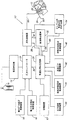
FIG. 1 is a functional block diagram illustrating a proportional airway
[0034]
Proportional airway
[0035]
Proportional airway
[0036]
In the preferred embodiment, the
[0037]
Further, the output of the
[0038]
An output signal from the
[0039]
As illustrated, when formed as a mask, the
[0040]
The
[0041]
The proportional positive
[0042]
In the present invention, the airway proportional positive pressure (PPAP)
[0043]
In a broad sense, airway proportional positive pressure (PPAP) therapy and airway proportional positive pressure (PPAP)
Pdelivered = Pbase + gain * flow
Where “Pdelivered” is the pressure applied to the subject's interface material, “Pbase” is the baseline pressure (greater than or equal to zero, conceptually equal to expiratory airway pressure (EPAP)), “flow "Is the approximate flow rate of the subject determined by the flow transducer, and" Gain "is a constant used to increase the pressure based on the flow rate. For the gain constant, one constant is precisely determined for the inspiratory action (positive flow), and a different constant is precisely determined for the expiratory action (negative flow).
[0044]
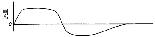
3A and 3B show that the proportional airway
[0045]
However, the airway proportional positive pressure (PPAP)
[0046]
However, away from this case, the optimal inspiration gain is not the optimal exhalation gain, and vice versa. Accordingly, the output of the airway proportional positive pressure (PPAP)
[0047]
Pinhalation = Pbase + GainInsp * Flow
as well as
Pexhalation = Pbase + GainExp * Flow
However, “GainInsp"Is a constant used during inspiration (positive flow) to increase pressure based on flow rate," GainExp"Is a constant used during exhalation (negative flow) to reduce pressure based on flow rate.
[0048]
Typically selected gain is about 0-10 cmH for inspiratory action2Has a range of O / liter / second. A higher increase value can be selected for inspiratory and / or expiratory effects as desired or necessary, but the gain that can be selected for exhalation is, for example, 0-4 cmH.2Usually in the range of O / litre / second below the intake gain.
[0049]
Regardless of the selected gain value, by applying a flow signal derived from a normal breathing pattern, the pressure rises above Pbase during inspiration and falls below Pbase during exhalation . That is, the output pressure approaches Pbase when the subject's breathing gas flow is near zero at the beginning and end of the inspiratory action as well as the beginning and end of the exhalation action.
[0050]
4A and 4B clearly illustrate the effect of selecting different gains in both the inspiratory and expiratory phases of the respiratory cycle having a pressure output curve. GainInsp (a), GainInsp (b), GainInsp (c)And GainInsp (d)Represents some of the infinitely wide gain values that can be applied during the inspiratory action in decreasing order. Similarly, GainExp (e), GainExp (f), GainExp (g)And GainExp (h)Indicates an increasing exhalation gain value. Any number of waveform expressions can be generated at different gain settings. For example, GainInspCan be set higher thanExpThe gain can be set to the same value for the inspiratory flow rate and the expiratory flow rate.
[0051]
In embodiments of the invention, airway proportional positive pressure (PPAP) therapy is intended to provide only the pressure necessary to prevent collapse of the airway at any given moment during the respiratory cycle. Thus, in general, the maximum pressure is applied at an appropriate time only when a negative airway inhalation peak pressure is detected, and the minimum pressure is applied at an appropriate time only when a positive airway exhalation peak pressure is detected. Become. At all other times during the breathing cycle, the airway proportional positive pressure (PPAP) device delivers air in response to the subject's breathing movement at a variable pressure in the range between the maximum and minimum pressures. As described above, it creates a selected gain at the moment of instantaneous flow (inspiration and expiration) and adds it continuously to form the instantaneous output pressure of the airway proportional positive pressure (PPAP) device. Management of high or zero basal pressure is included in airway proportional positive pressure (PPAP) treatment. The same gain can be selected for inspiration and expiration, but different gain values can be selected independently for inspiration and expiration. Basal pressure is the pressure required to overcome any mechanical crushing forces arising from airway tissue, muscle tension and physical condition. In other words, the basal pressure is approximately equal to “exhaled airway pressure (EPAP)” typically used for expiratory airway positive pressure or two-level airway proportional positive pressure (PPAP) therapy.
[0052]
In this regard, FIG. 5B shows an airway proportional positive pressure (PPAP) device compared to a conventional continuous airway positive pressure (CPAP) and two-level airway positive pressure (PAP) device on a single respiratory cycle. The pressure output curve generated by 10 is shown. Conventional continuous continuous airway positive pressure (CPAP) or as long as appropriate inspiratory and expiratory splint pressures are applied at time 48 (peak inspiratory flow), time 50 (start of expiration) and time 52 (end of expiration) A pressure lower than that delivered by two levels of positive airway pressure (PAP) therapy is delivered for another entire time during the respiratory cycle. This decreasing output pressure is represented by the “Airway Proportional Positive Pressure (PPAP)” curve of FIG. 5B. The hatched area in FIG. 5B shows two levels of airway positive pressure (PAP), airway proportional positive pressure (PPAP), airway inspiratory positive pressure (IPAP), and expiratory airway pressure (EPAP) phases during a typical respiratory cycle. Reflects the difference in pressure applied by. The hatched area conceptually indicates respiratory motion or motion mitigation due to airway proportional positive pressure (PPAP). As expected, the reduction in motion provides greater relief for subjects assisted by airway proportional positive pressure (PPAP) and increases cooperation in respiratory therapy. Thus, in the present invention, airway proportional positive pressure (PPAP) therapy provides subject comfort (and co-operation with treatment) given by continuous airway positive pressure (CPAP) or two levels of airway positive pressure (PAP) therapy. New respiratory insufficiency treatments can be performed that exceed treatment.
[0053]
Referring again to FIG. 1, in response to
[0054]
In normal breathing, a negative pressure gradient must be generated before flow begins. Therefore, the negative pressure waveform generated in the airway must induce the inspiratory flow prior to the start of the inspiratory action. For example, in the unstable airways unique to sleep apnea syndrome (OSAS), the negative relationship between the negative pressure gradient and the onset of inspiratory flow is sufficient to overcome the negative pressure in the airway if it cannot be accommodated by appropriate compensation measures. A situation where airway proportional positive pressure (PPAP) therapy does not produce pressure (due to low flow) can cause total or partial airway collapse. This problem can be solved by many methods. For example, a higher airway proportional positive pressure (PPAP) basal pressure can be used to support the airway at the beginning of inspiration by additional pressure. Alternatively, as shown in FIGS. 6A and 6B, the pressure is temporarily increased at the start of inspiration to support the airway until sufficient flow is generated to drive the airway proportional positive pressure (PPAP) method. It is possible. The present invention provides several practical ways in which pressure is applied during the desired phase of inspiration and the pressure supports the airway as the inspiratory flow increases.
[0055]
A
[0056]
Pinhalation = the larger one below
Pbase + GainInsp *flow
Or
Pbase + Pprofile
However, “Pinhalation” is the pressure supplied to the subject's interface during inspiration, “Pbase” is the baseline pressure (conceptually equal to the expiratory airway pressure (EPAP)), and “flow” is an estimate “Gain”Insp"Is a constant used during inspiration (positive flow) to increase pressure based on flow rate, and" Pprofile "is a function that generates pressure fluctuations to support the airway at the start of inspiration. This type of pressure variation function may be continuous, such as a step change or other functional shape, for example as shown by dotted line 58 in FIG. 6B, in a time base (eg, backward tilt change as shown by dotted line 60 in FIG. 6B).
[0057]
Alternatively, pressure fluctuations can be used only to control the output pressure for a predetermined initial portion of inspiration. The following equation shows the system output pressure during inspiratory action under this type of control condition.
[0058]
Pinhalation = Pprofile From breath start to X
as well as
Pinhalation = Pbase + GainInsp * From flow X to the start of expiration
However, “Pinhalation” is the pressure supplied to the subject's interface during inspiration, “Pbase” is the baseline pressure (conceptually equal to the expiratory airway pressure (EPAP)), and “flow” is Estimated subject gas flow, “GainInsp"Is a constant used during inspiration (positive flow) to increase pressure based on flow rate, and" Pprofile "is any function that produces pressure fluctuations that support the airway at the beginning of inspiration. This type of function may be a continuous shape or other functional shape such as a step change or time base, for example a backward slope change. “X” is a preselected transition point determined by analysis of the flow signal, such as time or curvature, percentage drop from peak flow, integral, derivative, conventional respiratory analysis or flow analysis and time combined. It is.
[0059]
The airway proportional positive pressure (PPAP)
[0060]
The method of the system of the present invention that solves the subject's need to change the controlled features of the airway proportional positive pressure (PPAP) such as continuous airway positive pressure (CPAP) shown in FIGS. 7A and 7B. To combine with therapy.
[0061]
With continuous positive airway pressure (CPAP), a single pressure is generated and delivered during the entire sleep period. Airway proportional positive pressure (PPAP) can be suitably coupled with continuous airway positive pressure (CPAP) to reduce the pressure delivered to the subject during exhalation. For pressures delivered under combined airway proportional positive pressure (PPAP) and continuous positive airway pressure (CPAP), the following equation is obtained:
Pinhalation = CPAP (continuous positive airway pressure)
as well as
Pexhalation = CPAP (continuous positive airway pressure) + GainExp *flow
However, “GainExp"Is a constant used during expiration (negative flow) to reduce pressure based on flow rate.
[0062]
8A and 8B illustrate that airway proportional positive pressure (PPAP) can be combined with two levels of airway positive pressure (PAP) therapy to form an effective therapeutic pressure waveform in various ways. The configuration of the airway proportional positive pressure (PPAP) and continuous airway positive pressure (CPAP) is almost the same, but one application example is airway proportional positive pressure (PPAP) that reduces the pressure during expiration. Is to use. The formula for supplying the combined pressure of synthetic airway proportional positive pressure (PPAP) and two-level airway positive pressure (PAP) is shown below:
Pinhalation = IPAP (Airway intake positive pressure)
as well as
Pexhalation = EPAP (expired airway pressure) + GainExp * Flow
However, “GainExp"Is a constant used during expiration (negative flow) to reduce pressure based on flow rate.
[0063]
Another method of combining airway proportional positive pressure (PPAP) with two levels of therapy is to provide the subject with airway inspiratory positive pressure (IPAP) for the first part of the inspiratory cycle, as shown in FIGS. 9A and 9B. Apply and apply airway proportional positive pressure (PPAP) to the rest of the respiratory cycle. Gain for each breath based on positive airway inspiratory pressure (IPAP) and flow rateInspIs automatically calculated by the following formula:
Pinhalation (t0~ Tl) = IPAP (Airway intake positive pressure)
Pinhalation (tl~ T2) = Pbase + AutoGainInsp * Flow
as well as
Pexhalation = Pbase + GainExp * Flow
Where “flow” is the estimated flow rate, “t0"Is the time when breathing starts," t1"Is the point in time when the estimated flow is a predetermined percentage of the inspiratory peak flow," t2”Is the exhalation start time,“ IPAP ”is the positive airway inspiration positive pressure applied continuously,“ Pinhalation (t0~ Tl) ”At time t0To t1The pressure supplied to the subject until "Pbase" is the continuous basal pressure, "AutoGainInspIs at time t1Equal to (IPAP-Pbase) / flow in, “Pinhalation (tl~ T2) ”At time t1To t2The pressure supplied to the subject until "GainExp"Is a constant used during exhalation to reduce the pressure delivered to the subject, and" Pexhalation "is the pressure delivered to the subject during exhalation.
[0064]
The flow output curves and airway proportional positive pressure (PPAP) pressure output curves shown in FIGS. 3A-9B show the pressure and flow output by the device during the inspiration and expiration phases of a single respiratory cycle. Airway proportional positive pressure (PPAP) curves and flow curves, of course, vary from breathing cycle to breathing cycle according to the subject's breathing conditions, particularly under fully automated airway proportional positive pressure (PPAP) therapy, as described below. It seems to change minute. Furthermore, somewhat greater variations may occur during the respiratory cycle associated with different phases of the extended treatment period, particularly during sleep apnea syndrome (OSAS) treatment.
[0065]
FIG. 2 represents another preferred embodiment of an airway proportional positive pressure (PPAP) device 10 'according to the present invention. Except for the additive airway inspiratory positive pressure (IPAP) / expiratory state airway pressure (EPAP) (two-level airway proportional positive pressure (PPAP))
[0066]
In the present invention, the pressure to be supplied to the subject is determined by the basic pressure, flow rate, and gain (and pressure fluctuations if used). These settings can be adjusted as needed for airway stabilization for a given subject condition. In sleep apnea syndrome (OSAS), the subject's periodic conditions, that is, the minimum and instantaneous conditions, vary depending on the sleep state and physical condition. Thus, even if the settings function well enough during a part of the sleep period, the settings do not function as well at different times. In other words, the setting that supports the airway in the most unstable state allows the pressure to rise above the required level during a more stable time. Similarly, a setting that works well at one point in time may not be sufficient at other points in time.
[0067]
The present invention proposes several ways to minimize the effects of subject changes necessary to optimize airway proportional positive pressure (PPAP) therapy. One way is to automatically adjust gain, pressure fluctuations and baseline pressure to meet subject requirements. This adjustment can be, for example, size, shape, derivative, integral (volume), pressure, hemorrhoids, arterial oxygen saturation, discharged CO2, Based on analysis of subject parameters related to flow, such as airway diameter or other factors.
[0068]
Using one or more of the above factors (parameters), the gain of the systemInspCan be adjusted to prevent partial airway respiratory depression. The goal of this system is Gain to respond to any of the following subject conditions:InspIs to increase:
° Reduction of intake flow;
° Reduction in intake volume;
° Increased airway resistance as determined by flow or pressure signal analysis;
° airway instability indicated by changes in pressure or sound;
° reduced oxygen saturation in the artery; or
° Reducing airway diameter
[0069]
Also, in the apparatus according to the present invention, if these conditions do not exist, the minimum gain is obtained.InspCan be maintained.
Also, in current systems, the basal pressure (Pbase) can be adjusted to prevent complete collapse of the airway (breathing arrest) or dangerous collapse (dangerous hypopnea). Respiratory arrest can be detected by analyzing flow signals and / or reflected pressure waves or a combination of pressure and flow to determine airway opening. In addition, it may be important to determine whether respiratory arrest has occurred due to airway collapse or respiratory movement defects. If an obstruction event is detected, the basal pressure can be increased to open the airway. Another performance of the system of the present invention is to maintain a minimum Pbase when the above conditions do not exist.
[0070]
Further, in the system of the present invention, the pressure fluctuation (Pprofile) can be adjusted to prevent breathing stop or breathing reduction at the start of the inspiration action. Thus, in the system of the present invention, increased airway resistance, pressure fluctuations or changes in sound indicative of airway instability, decreased oxygen saturation in the arteries, decreased airway diameter, or exhaled CO2Pprofile can be increased in response to a decrease in inspiratory flow, a change in respiratory volume, flow waveform analysis, etc. The present invention has the function of maintaining the minimum pressure fluctuation when the above condition does not exist.
[0071]
FIG. 10 illustrates a preferred embodiment of a fully automated airway proportional positive pressure (PPAP)
[0072]
Proportional airway positive pressure device 10 '' also detects a decrease in respiration due to a decrease in peak flow and / or periodic volume during a predetermined feedback, and a respiration due to a significant decrease in flow during a predetermined period. Has the ability to detect the occurrence of a stop. For example, to detect hypopnea, compare the short-term average of inspiratory peak flow or periodic volume (eg, 3 breath average) with the peak flow or periodic volume (long-term average of
[0073]
The present invention further includes a method for determining whether the airway is open (central respiratory arrest) or blocked (obstructive respiratory arrest) during respiratory arrest. Once a long-term respiratory arrest is detected, the system follows the command of the
[0074]
In the preferred embodiment, the control of the airway proportional positive pressure (PPAP)
[0075]
Although not shown, in further embodiments of the invention, fully automated airway proportional positive pressure (PPAP), continuous airway positive pressure (CPAP) and / or two levels of airway positive pressure (PAP) therapy, Can be combined. In these cases, Gain in a fully automated airway proportional positive pressure (PPAP) systemInspBy using the same logic to control, continuous airway positive pressure (CPAP) or airway inspiration positive pressure (IPAP) can be controlled. Similarly, Pbase can be controlled in a manner similar to that described for fully automated airway proportional positive pressure (PPAP).
[0076]
Fully automated airway proportional positive pressure (PPAP)-continuous airway positive pressure (CPAP) or airway proportional positive pressure (PPAP)-2 level airway positive pressure (PAP) system to adjust Pprofile and It is possible to prevent respiratory stop or hypopnea at the start. Thus, with this type of system, continuous positive airway pressure (CPAP) (or positive airway inspiratory pressure (IPAP)) or Pprofile can be increased in the face of any of the following subject conditions:
° Reduction of intake flow;
° reduction in inspiratory volume;
° Increased airway resistance as determined by flow signal analysis or pressure signal analysis;
° airway instability indicated by pressure or sound changes;
° reduced oxygen saturation in the arteries;
° Airway diameter reduction.
[0077]
When the above conditions do not exist, continuous airway positive pressure (CPAP) or airway inspiratory positive pressure (IPAP) is maintained at a minimum level.
[0078]
Therefore, if you use airway proportional positive pressure (PPAP) therapy, you can add airway proportional positive pressure (PPAP) in response to expiratory flow to treat sleep apnea syndrome (OSAS) during expiration. Similar to the above method of reducing the pressure below Pbase, the pressure applied during expiration can be reduced to a level below the subject's end-expiratory pressure (PEEP) level throughout the end of the expiration phase. Thus, by reducing the pressure applied during the expiratory phase below the end-expiratory pressure (PEEP), the breathing action is compared to the constant expiratory pressure applied during the expiratory airway pressure (EPAP). This can increase the comfort of the subject. In fact, airway proportional positive pressure (PPAP) can be adapted to any ventilation mode that uses end expiratory pressure (PEEP). This application may include pressure retention by end-expiratory pressure (PEEP), proportional assisted ventilation (PAV) by end-expiratory pressure (PEEP) or other applications of end-expiratory pressure (PEEP) in respiratory assistance therapy .
[0079]
In addition, during the inspiratory phase, oxygen can be easily managed with airway proportional positive pressure (PPAP) therapy to treat subjects with chronic obstructive pulmonary disease (COPD) who require supplemental oxygen.
[0080]
The present invention can control the pressure of the gas supplied to the subject by changing with respect to time. For example, in one embodiment of the invention, the pressure delivered to the subject from the first minimum pressure to the desired therapy pressure can be increased over the entire period. This ramp pressure increase can give the subject time to sleep under a relatively low pressure that is increased to therapy pressure over time. Thereafter, the pressure increases and therapeutic pressure is applied after the subject sleeps. In the morning, the reverse process can be performed, and the pressure is reduced from the treatment pressure just before the subject attempts to wake up. The
[0081]
An example of a technique for controlling the pressure level delivered to a subject by one or more pressure ramps, as well as other methods of controlling the subject's pressure, is a U.S. patent referenced as part of this specification. No. 5,492,114 and 5,551,418 and US Reissue Patent RE 35,295. Many of the techniques disclosed in these US patents can be combined with the devices and methods of the present invention to provide the optimal therapy necessary to treat a subject.
[0082]
In yet another embodiment of the present invention,
[0083]
In the present invention, the AutoGainInspBy limiting the value for the automatically determined gain, such as, for example, the automatically determined gain that exceeds the limit due to the excessively high pressure supplied to the subject is set to a predetermined limit value. This can be prevented. The gain itself can be changed by changing the limit value over a predetermined period. In addition, the change value that can be implemented within the gain that is automatically determined over a predetermined period is also controlled to prevent the gain that is automatically determined over a predetermined period and exceeding the predetermined value from changing. be able to.
[0084]
When using airway proportional positive pressure (PPAP) for the treatment of congestive heart failure (CHF), the present invention reduces intermediate pressure and expiratory activity while delivering the same level of rest to the heart. Heart preload and afterload (preferably 5-10 cm H2By applying a positive basal pressure approximately equal to the pressure required for reduction (in the range of O), the present invention reduces the burden on the heart. The additional positive pressure between the inspiratory effects, which is proportional to the respiratory action, allows the subject to overcome the negative pressure effects that occur during the inspiratory effects. Airway proportional positive pressure (PPAP) is particularly suited for congestive heart failure (CHF) subjects in that typical congestive heart failure (CHF) subjects have normal adaptability. The subject can estimate most of the respiratory load from the flow signal. By reducing the pressure below the basal pressure during exhalation, the subject can reduce exhalation activity without reducing the benefit to the heart. Even if the respiratory action is reduced and the average pressure is reduced, the benefit to the heart from the net effect is the same.
[0085]
Similar to the use of airway proportional positive pressure (PPAP) therapy to prevent airway collapse, airway proportional positive pressure (PPAP) therapy to treat congestive heart failure (CHF) is the pressure required to reduce heart preload and afterload. Only supply a minimum amount of. This applies a basal pressure equal to the pressure required to reduce the pre-load and post-load of the heart in the absence of respiratory load, while minimizing respiratory motion while minimizing respiratory motion. The changing pressure required to overcome the effect of respiratory load on the load can be provided.
[0086]
Providing positive pressure outside the heart via the respiratory system has two advantages: First, the enlarged heart of a congestive heart failure (CHF) subject is reduced to near normal size by positive pressure. By returning to normal size, the heart muscles can be operated more efficiently. Second, the positive pressure in the thoracic cavity reduces the amount of pressure that the heart overcomes to pump blood to other parts of the body.
[0087]
The heart and chest cavity are at the same pressure. In general, this pressure fluctuates around ambient pressure due to the effects of respiratory load. The circulatory system varies with the pumping action of the heart, but has an average working pressure of 100 mmHg in subjects with normal tension. The heart must exert the force to pump blood from the thoracic cavity to the pressurized blood circulation system. By increasing the pressure in the thoracic cavity, the amount of pressure that the heart must pump blood can be reduced. 10cmH2A pressure in the thoracic cavity that is O or approximately 10 mm Hg can reduce the heart burden by 10 mm Hg / 100 mm Hg or approximately 10%.
[0088]
The effects of respiratory action on the heart are as follows: During inspiration, the pressure on the chest (which surrounds the heart) becomes more negative with respect to other parts of the body. This increasing negative pressure increases the amount of pressure that the heart generates to pump blood from the chest cavity to the body. By supplying a pressure that exceeds the basal pressure during inspiration, airway proportional positive pressure (PPAP) can compensate for the decrease in chest pressure and keep the pressure in the chest relatively constant.
[0089]
During expiration, the pressure in the chest is less negative than the rest of the body. By reducing the pressure during expiration, airway proportional positive pressure (PPAP) can compensate for the increase in pressure in the thoracic cavity and keep the pressure in the chest relatively constant.
[0090]
During exhalation, the lower baseline is set by the variable part of the airway proportional positive pressure (PPAP) by minimizing the decrease in pressure and utilizing the increasing pressure, using a constant pressure, identical to the heart Can give you the advantage. By lowering the baseline and reducing pressure during exhalation, breathing motion can be reduced and the subject's comfort can be enhanced.
[0091]
It is desirable to implement an airway proportional positive pressure (PPAP) variant similar to the structure shown in FIG. 7 for an existing continuous positive airway pressure (CPAP) device. A variation of airway proportional positive pressure (PPAP) on existing continuous airway positive pressure (CPAP) devices enhances subject comfort and includes a new continuous airway positive pressure (CPAP) that includes airway proportional positive pressure (PPAP) mode ) Cooperation can be obtained without significant financial or other burdens associated with the manufacture and installation of equipment. Performing airway proportional positive pressure (PPAP) therapy with a continuous positive airway pressure (CPAP) device can be performed in various ways, eg, as described with respect to FIGS. 7A and 7B.
[0092]
As shown in FIG. 7, when the reactive components used to generate a pressure curve that decreases during exhalation are exchanged for a predetermined decreasing pressure fluctuation, a more economical method of continuous airway positive pressure ( A variation of airway proportional positive pressure (PPAP) can be implemented in the CPAP system. This pressure fluctuation is exchanged for a constant continuous positive airway pressure (CPAP) pressure that the subject applies in different states by the continuous positive airway pressure (CPAP) device during the expiratory phase of the respiratory cycle. In a preferred embodiment of the present invention, the predetermined pressure fluctuation has a shape that substantially corresponds to the normal flow of the subject.
[0093]
FIGS. 11A and 11B are graphs showing flow and pressure similar to FIGS. 7A and 7B showing the apparatus pressure curve output obtained by another embodiment of the present invention utilizing a simplified pressure fluctuation generation technique. It is. The
Pinhalation = CPAP (continuous positive airway pressure)
Pexhalation = CPAP (continuous positive airway pressure)-(predetermined pressure fluctuation).
[0094]
The predetermined pressure variation used to reduce continuous positive airway pressure (CPAP) pressure is 0-4 cmH, mainly by respiratory therapists.2A magnitude M selected within the range of O and, unlike the pressure curve of FIG. 7B, has a duration D that is not directly determined based on the subject's instantaneous flow rate or volume. The magnitude M indicates the pressure drop from a constant continuous positive airway pressure (CPAP) value. The value of duration D is preferably a fraction of the subject's average expiration period.
[0095]
A number of predetermined pressure fluctuations having different magnitudes, durations or both can be stored in a continuous positive airway pressure (CPAP) / airway proportional positive pressure (PPAP) device and supplied to the subject. FIG. 11B shows three predetermined pressure fluctuations P1, P2 and P3 having magnitudes M1, M2 and M3 and durations D1, D2 and D3, respectively. In a preferred embodiment of the present invention, during exhalation, the pressure delivered to the subject is a pressure generated from airway proportional positive pressure (PPAP) based on flow rate or volume, for example as shown in FIGS. 3A and 3B. The pressure variation is selected to approximately signify the variation. As shown in FIG. 11B, the pressure drops rapidly at the start of exhalation and then gradually increases toward the baseline continuous positive airway pressure (CPAP).
[0096]
This embodiment of the continuous airway positive pressure (CPAP) / airway proportional positive pressure (PPAP) device is a flow signal or pressure signal from the subject, as in the case of the airway proportional positive pressure (PPAP) device and the technique described above. Based on the above, the flow rate and / or pressure supplied to the subject is not controlled, but is merely detected at the start or inspiratory action and / or expiratory action. It doesn't have to be as accurate. For example, an expiratory respiratory flow meter can be replaced with a thermistor or thermocouple to determine the expiration state and expiration state. In addition, the pressure control valve can be omitted by generating a pressure fluctuation supplied to the subject during the exhalation phase using a speed control type motor.
[0097]
Although an embodiment has been described in which predetermined pressure fluctuations are used to reduce continuous positive airway pressure (CPAP) during exhalation, the same technique can be applied to a two-level pressure assist device, e.g. The two-level expiratory state airway pressure (EPAP) can be reduced by pressure fluctuations to form the pressure curve shown in FIG. 8B.
[0098]
When airway proportional positive pressure (PPAP) is performed and the gain is set beyond a certain value, for example exceeding the range of 2-3 cm / liter / second, the pressure generated by the device tends to become unstable There was found. That is, as shown in FIG. 12, a
[0099]
In spite of the possibility of this vibration, the pressure supplied to the subject at the start of exhalation is relatively greatly reduced while maintaining as smooth a pressure fluctuation as possible during the remaining time of the exhalation phase. Is desirable. In one embodiment of the invention, this can be achieved by supplying pressure to the subject during exhalation according to the following formula:
Pexhalation = Greater than:
Pbase-(GainExp *flow)
Or
Current pressure,
However, “current pressure” is the pressure supplied to the subject at that time during the exhalation phase.
[0100]
FIG. 13 shows a
[0101]
By ensuring that the pressure supplied to the subject is always greater than the current pressure and the calculated pressure, the pressure experienced by the subject during exhalation does not oscillate. If the pressure to be supplied to the subject begins to decrease below the current pressure, the device prevents a pressure decrease below the current pressure by continuing to supply the current pressure to the subject without using the calculated pressure.
[0102]
In a second embodiment according to the invention, pressure oscillations can be avoided using a completely different calculation method for determining the pressure delivered to the subject during the exhalation phase. Instead of forming a basis for calculating the pressure supplied to the subject based on the flow of the subject operated with a gain selected either manually or automatically as in the previous embodiment, it should be supplied to the subject The pressure is calculated based on the amount of gas still contained in the lung, as shown as the amount to be discharged. The amount to be discharged corresponds to the difference between the current gas volume in the subject and the gas volume in the subject in a resting state. The gas volume in the lung can be easily estimated from the current flow signal. The gas volume in the resting subject is determined using conventional techniques and can be updated periodically to reliably improve calculation accuracy.
[0103]
In this embodiment, the pressure output by the airway proportional positive pressure (PPAP) device at least during the exhalation phase is represented by the following equation that can be encoded into an airway proportional positive pressure (PPAP) circuit:
Pexhalation = Pbase − (Volumeto be exhaled * GainExp)
However, “Pbase” is the baseline pressure (equal to zero exhalation airway pressure (EPAP) above zero), “Volumeto be exhaled"Is the difference between the current gas volume in the subject minus the gas volume of the resting subject," GainExp"Is a constant used during expiration (negative flow) for pressure reduction.
[0104]
The pressure output during the inspiratory phase is determined using the technique. FIG. 14 shows a
[0105]
Volume of gas to be discharged (Volumeto be exhaled) Is relatively large at the beginning of the exhalation phase, so the initial pressure drop in the exhalation phase is very large. It is preferable to smooth out the large pressure drop at the beginning of the exhalation phase by adding an attenuation factor to the calculation of the pressure to be supplied to the subject.
[0106]
There are many techniques that can be used to attenuate the initial pressure drop at the beginning of the exhalation phase. However, in a preferred embodiment of the present invention, the pressure supplied to the subject during the exhalation phase is expressed as:
Start of exhalation phase (t0) To X:
[Formula 1]
![]()
Pexhalation = Pbase-(Volumeto be exhaled * GainExp)
Where “t” is the current time following the start of the expiratory phase, “X” is the time or eg time, curvature, percentage drop from peak flow, integral value, derivative, prior breath analysis or flow analysis and time The transition point is predetermined after the start of the expiration phase determined by analysis of the flow signal such as a combination of
[0107]
As shown in FIG. 14, in consideration of the attenuation coefficient (attenuation factor) t / X, t0The X value is selected to reduce the pressure drop at the start of exhalation by calculating the pressure delivered to the subject during the initial period from to. Thereafter, exhalation pressure to be applied to the subject is calculated according to the second equation of the above two equations without considering the attenuation factor. Thus, in this embodiment of the invention, the pressure curve is smooth throughout the entire exhalation phase while ensuring that the initial pressure drop at the start of exhalation is within a predictable parameter range.
[0108]
In this embodiment, other attenuation techniques can be used that smooth the magnitude of the initial pressure drop at the start of the exhalation phase. Therefore, the present invention is not limited to the attenuation technique.
[0109]
The present invention has been described for the purpose of illustrating the best mode of the present invention, but the above description is only for the purpose of illustration, and the present invention is not limited to the above-described embodiment. All modifications and equivalent devices falling within the spirit of the invention are included.
[Brief description of the drawings]
FIG. 1 is a block diagram illustrating the function of an apparatus according to the present invention.
FIG. 2 is a block diagram showing the function of another embodiment of the device according to the invention.
FIGS. 3A and 3B visually illustrate a general method by which a device according to the present invention outputs pressurized breathing gas to a subject in a proportional state during both the inspiratory and expiratory phases of a single respiratory cycle. Graph showing flow rate and pressure
4A and 4B, similar to FIGS. 3A and 3B, respectively, are multiple device output pressure curves achieved by selectively adjusting the inspiratory and expiratory gain setting controls of the proportional airway positive pressure circuit of the present invention. Showing flow rate and pressure illustrating
FIGS. 5A and 5B are graphs showing flow and pressure comparing pressure output curves of a conventional respiratory assistance device, as well as pressure output curves typical of a device according to the present invention, similar to FIGS. 3A and 3B, respectively.
FIGS. 6A and 6B are graphs showing flow and pressure representing selective pressure fluctuations used at the beginning of the inspiratory phase of breathing to facilitate the onset of inspiration, similar to FIGS. 3A and 3B, respectively.
7A and 7B, similar to FIGS. 3A and 3B, respectively, are graphs showing flow rates and pressures representing apparatus pressure output curves according to other embodiments of the present invention.
8A and 8B, similar to FIGS. 3A and 3B, respectively, flow rate and pressure representing a device pressure output curve obtained by combining a conventional two-level positive airway pressure therapy with a proportional positive airway pressure therapy according to the present invention. Diagram showing
FIGS. 9A and 9B, similar to FIGS. 3A and 3B, respectively, show a device pressure output curve further obtained by combining a conventional two-level airway positive pressure treatment with a proportional airway positive pressure treatment according to the present invention, and Graph showing pressure
FIG. 10 is a block diagram showing a further embodiment of the device according to the invention.
FIGS. 11A and 11B, similar to FIGS. 7A and 7B, respectively, show flow and pressure graphs showing apparatus pressure output curves obtained with other embodiments of the present invention utilizing a simplified pressure variation technique. FIGS.
FIG. 12 is a graph showing pressure oscillations supplied to a subject during exhalation
13 is a graph showing pressure according to the first technique for reducing the vibration shown in FIG.
14 is a graph showing pressure according to the second technique for reducing the vibration shown in FIG.
[Explanation of symbols]
14 ...
Claims (16)
被験者の気道と気流発生器とを接続する被験者用界面材と、
被験者用界面材内を流れる気体の流体特性を検出して、流体特性に対応する検出信号を発生するセンサと、
気流発生器及び被験者の界面材の少なくとも一方に設けられかつ気流発生器により供給される呼吸用気体の圧力を制御する圧力コントローラと、
センサから検出信号を受信して圧力コントローラを制御し、呼吸サイクルの少なくとも一部の間に最小限に充分な圧力で被験者に呼吸用気体を供給して、
(1) 呼吸負荷の不存在中に心臓の前負荷及び後負荷の減少に必要な圧力と、心臓の前負荷及び後負荷の際に呼吸負荷による影響を克服するのに必要な圧力との和となる最小限に充分な圧力で心臓の前負荷及び後負荷を減少する、
(2) 気道圧潰の防止に必要な圧力となる最小限に充分な圧力で気道圧潰を防ぐ、
2機能の少なくとも一つを所与の時点で実行する制御手段と、
制御手段に作動接続されかつ選択的に第1の利得を決める第1のセレクタユニットとを備え、
制御手段は、圧力コントローラを制御して、呼気作用の間の流体特性の振動を防止し、圧力コントローラを制御して、第1のセレクタユニットからの第1の利得及びセンサからの検出信号に基づいて呼吸サイクルの少なくとも一部の間で最小限に充分な圧力で呼吸用気体を被験者の気道に送出することを特徴とする呼吸用加圧気体供給装置。An air flow generator,
A subject interface material connecting the subject's airway and the airflow generator;
A sensor that detects a fluid characteristic of a gas flowing in the interface material for a subject and generates a detection signal corresponding to the fluid characteristic;
A pressure controller provided on at least one of the airflow generator and the subject's interface and controlling the pressure of the breathing gas supplied by the airflow generator;
Receiving a detection signal from the sensor and controlling the pressure controller to supply a breathing gas to the subject with a minimally sufficient pressure during at least part of the breathing cycle;
(1) The sum of the pressure required to reduce the heart preload and afterload in the absence of the respiratory load and the pressure required to overcome the effects of the respiratory load during the heart preload and afterload. Reduce the preload and afterload of the heart with a minimum sufficient pressure
(2) Prevent airway crushing with a minimum sufficient pressure to prevent airway crushing,
Control means for performing at least one of the two functions at a given time;
A first selector unit operatively connected to the control means and selectively determining a first gain;
The control means controls the pressure controller to prevent fluid characteristic oscillations during exhalation and controls the pressure controller based on the first gain from the first selector unit and the detection signal from the sensor. A pressurized pressurized gas supply device for breathing, wherein the breathing gas is delivered to the subject's respiratory tract at a minimally sufficient pressure during at least a portion of the breathing cycle.
被験者の気道と気流発生器とを接続する被験者用界面材と、
被験者用界面材内を流れる気体の流体特性を検出して、流体特性に対応する検出信号を発生するセンサと、
気流発生器及び被験者の界面材の少なくとも一方に設けられかつ気流発生器により供給される呼吸用気体の圧力を制御する圧力コントローラと、
センサから検出信号を受信して圧力コントローラを制御し、呼吸サイクルの少なくとも一部の間に最小限に充分な圧力で被験者に呼吸用気体を供給して、
(1) 呼吸負荷の不存在中に心臓の前負荷及び後負荷の減少に必要な圧力と、心臓の前負荷及び後負荷の際に呼吸負荷による影響を克服するのに必要な圧力との和となる最小限に充分な圧力で心臓の前負荷及び後負荷を減少する、
(2) 気道圧潰の防止に必要な圧力となる最小限に充分な圧力で気道圧潰を防ぐ、
2機能の少なくとも一つを所与の時点で実行する制御手段と、
制御手段に作動接続されかつ選択的に第1の利得を決める第1のセレクタユニットと、
一定期間にわたり第1の最小圧力から最小限に充分な圧力まで被験者に供給される気体の圧力を作動時に増加する手段とを備え、
制御手段は、圧力コントローラを制御して、第1のセレクタユニットからの第1の利得及びセンサからの検出信号に基づいて呼吸サイクルの少なくとも一部の間に最小限に充分な圧力で呼吸用気体を被験者の気道に送出することを特徴とする呼吸用加圧気体供給装置。An air flow generator,
A subject interface material connecting the subject's airway and the airflow generator;
A sensor that detects a fluid characteristic of a gas flowing in the interface material for a subject and generates a detection signal corresponding to the fluid characteristic;
A pressure controller provided on at least one of the airflow generator and the subject's interface and controlling the pressure of the breathing gas supplied by the airflow generator;
Receiving a detection signal from the sensor and controlling the pressure controller to supply a breathing gas to the subject with a minimally sufficient pressure during at least part of the breathing cycle;
(1) The sum of the pressure required to reduce the heart preload and afterload in the absence of the respiratory load and the pressure required to overcome the effects of the respiratory load during the heart preload and afterload. Reduce the preload and afterload of the heart with a minimum sufficient pressure
(2) Prevent airway crushing with a minimum sufficient pressure to prevent airway crushing,
Control means for performing at least one of the two functions at a given time;
A first selector unit operatively connected to the control means and selectively determining a first gain;
Means for increasing in operation the pressure of the gas supplied to the subject from a first minimum pressure to a minimum sufficient pressure over a period of time;
The control means controls the pressure controller so that the breathing gas is at a minimum sufficient pressure during at least part of the breathing cycle based on the first gain from the first selector unit and the detection signal from the sensor. Is supplied to the subject's respiratory tract.
被験者の気道と気流発生器とを接続する被験者用界面材と、
被験者用界面材内を流れる気体の流体特性を検出して、流体特性に対応する検出信号を発生するセンサと、
気流発生器及び被験者の界面材の少なくとも一方に設けられかつ気流発生器により供給される呼吸用気体の圧力を制御する圧力コントローラと、
センサから検出信号を受信して圧力コントローラを制御し、呼吸サイクルの少なくとも一部の間に最小限に充分な圧力で被験者に呼吸用気体を供給して、
(1) 呼吸負荷の不存在中に心臓の前負荷及び後負荷の減少に必要な圧力と、心臓の前負荷及び後負荷の際に呼吸負荷による影響を克服するのに必要な圧力との和となる最小限に充分な圧力で心臓の前負荷及び後負荷を減少する、
(2) 気道圧潰の防止に必要な圧力となる最小限に充分な圧力で気道圧潰を防ぐ、
2機能の少なくとも一つを所与の時点で実行する制御手段と、
自動的に決定されかつ所定範囲外の値に該当する第1の利得に応答して作動される警報装置とを備え、
制御手段は、圧力コントローラを制御して、第1のセレクタユニットからの第1の利得及びセンサからの検出信号に基づいて呼吸サイクルの少なくとも一部の間に最小限に充分な圧力で呼吸用気体を被験者の気道に送出することを特徴とする呼吸用加圧気体供給装置。An air flow generator,
A subject interface material connecting the subject's airway and the airflow generator;
A sensor that detects a fluid characteristic of a gas flowing in the interface material for a subject and generates a detection signal corresponding to the fluid characteristic;
A pressure controller provided on at least one of the airflow generator and the subject's interface and controlling the pressure of the breathing gas supplied by the airflow generator;
Receiving a detection signal from the sensor and controlling the pressure controller to supply a breathing gas to the subject with a minimally sufficient pressure during at least part of the breathing cycle;
(1) The sum of the pressure required to reduce the heart preload and afterload in the absence of the respiratory load and the pressure required to overcome the effects of the respiratory load during the heart preload and afterload. Reduce the preload and afterload of the heart with a minimum sufficient pressure
(2) Prevent airway crushing with a minimum sufficient pressure to prevent airway crushing,
Control means for performing at least one of the two functions at a given time;
An alarm device automatically activated and activated in response to a first gain corresponding to a value outside a predetermined range;
The control means controls the pressure controller so that the breathing gas is at a minimum sufficient pressure during at least part of the breathing cycle based on the first gain from the first selector unit and the detection signal from the sensor. Is supplied to the subject's respiratory tract.
前記被験者の前記気道に気流発生器を接続する被験者用界面材と、
呼吸サイクルの呼気段階と吸気段階との間の差異を示す被験者の少なくとも一つの生理的状態を検出して、生理的状態を表す信号を生ずるセンサと、
気流発生器及び被験者用界面材の少なくとも一つに接続されかつ気流発生器により供給される呼吸用気体の圧力を制御する圧力コントローラと、
圧力コントローラを制御して、呼吸サイクルの吸気段階の少なくとも一部の間に第1の圧力レベルで被験者に呼吸用気体を供給し、呼吸サイクルの呼気段階の間に予め定められた圧力変動に従って被験者に呼吸用気体を供給する制御手段とを備え、
被験者の監視された呼吸特性から独立して予め定められた圧力変動波形を設定することを特徴とする被験者の気道に加圧された呼吸用気体を供給する比例正圧気体供給装置。An air flow generator,
A subject interface material connecting an airflow generator to the airway of the subject;
A sensor that detects at least one physiological condition of the subject indicative of a difference between the expiratory and inspiratory phases of the respiratory cycle and produces a signal representative of the physiological condition;
A pressure controller connected to at least one of the airflow generator and the subject interface and controlling the pressure of the breathing gas supplied by the airflow generator;
A pressure controller is controlled to supply breathing gas to the subject at a first pressure level during at least a portion of the inspiratory phase of the respiratory cycle, and the subject according to a predetermined pressure variation during the expiratory phase of the respiratory cycle Control means for supplying breathing gas to
A proportional positive pressure gas supply device for supplying a pressurized breathing gas to a subject's airway, wherein a predetermined pressure fluctuation waveform is set independently of the subject's monitored breathing characteristics.
送風機により発生する気体流を被験者の気道に供給する配給導管と、
配給導管内の気体又は気体流に関する特性を監視して、この特性に関する信号を発生するセンサと、
送風機、配給導管又は送風機及び配給導管に取り付けられて、配給導管内の気体の圧力を制御する圧力コントローラと、
圧力コントローラを制御して、呼吸周期の吸気段階の少なくとも一部の間に第1の圧力レベルで被験者に気体流を供給すると共に、呼吸周期の呼気段階の少なくとも一部の間に減少された圧力変動で被験者に気体流を供給する制御手段とを備え、
減少された圧力変動は、圧力変動、大きさ及び持続期間を有し、減少された圧力変動は、呼気段階の初期前に決定される非直線的変化に対応することを特徴とする被験者の気道に加圧気体を供給する供給装置。A blower,
A distribution conduit for supplying a gas flow generated by the blower to the subject's airway;
A sensor for monitoring a characteristic relating to gas or gas flow in the distribution conduit and generating a signal relating to this characteristic;
A pressure controller attached to the blower, distribution conduit or blower and distribution conduit to control the pressure of the gas in the distribution conduit;
Controlling the pressure controller to provide a flow of gas to the subject at a first pressure level during at least a portion of the inspiratory phase of the respiratory cycle and a reduced pressure during at least a portion of the expiratory phase of the respiratory cycle A control means for supplying a gas flow to the subject by variation,
The reduced pressure fluctuation has a pressure fluctuation, magnitude and duration, and the reduced pressure fluctuation corresponds to a non-linear change determined prior to the beginning of the exhalation phase. Supply device that supplies pressurized gas to the tank.
Applications Claiming Priority (3)
| Application Number | Priority Date | Filing Date | Title |
|---|---|---|---|
| US09/041,195 | 1998-03-12 | ||
| US09/041,195 US6105575A (en) | 1994-06-03 | 1998-03-12 | Method and apparatus for providing positive airway pressure to a patient |
| PCT/US1999/005325 WO1999045989A1 (en) | 1998-03-12 | 1999-03-11 | Method and apparatus for providing positive airway pressure to a patient |
Related Child Applications (1)
| Application Number | Title | Priority Date | Filing Date |
|---|---|---|---|
| JP2007320098A Division JP4758413B2 (en) | 1998-03-12 | 2007-12-11 | Supply device for supplying pressurized gas to the subject's airway |
Publications (3)
| Publication Number | Publication Date |
|---|---|
| JP2002505924A JP2002505924A (en) | 2002-02-26 |
| JP2002505924A5 JP2002505924A5 (en) | 2005-11-17 |
| JP4081239B2 true JP4081239B2 (en) | 2008-04-23 |
Family
ID=21915256
Family Applications (2)
| Application Number | Title | Priority Date | Filing Date |
|---|---|---|---|
| JP2000535400A Expired - Lifetime JP4081239B2 (en) | 1998-03-12 | 1999-03-11 | A device that supplies positive pressure to the subject's airways |
| JP2007320098A Expired - Lifetime JP4758413B2 (en) | 1998-03-12 | 2007-12-11 | Supply device for supplying pressurized gas to the subject's airway |
Family Applications After (1)
| Application Number | Title | Priority Date | Filing Date |
|---|---|---|---|
| JP2007320098A Expired - Lifetime JP4758413B2 (en) | 1998-03-12 | 2007-12-11 | Supply device for supplying pressurized gas to the subject's airway |
Country Status (7)
| Country | Link |
|---|---|
| US (2) | US6105575A (en) |
| EP (2) | EP2184080A1 (en) |
| JP (2) | JP4081239B2 (en) |
| AU (1) | AU3080199A (en) |
| CA (1) | CA2323455A1 (en) |
| DE (1) | DE69942719D1 (en) |
| WO (1) | WO1999045989A1 (en) |
Families Citing this family (240)
| Publication number | Priority date | Publication date | Assignee | Title |
|---|---|---|---|---|
| US7081095B2 (en) * | 2001-05-17 | 2006-07-25 | Lynn Lawrence A | Centralized hospital monitoring system for automatically detecting upper airway instability and for preventing and aborting adverse drug reactions |
| US20050062609A9 (en) * | 1992-08-19 | 2005-03-24 | Lynn Lawrence A. | Pulse oximetry relational alarm system for early recognition of instability and catastrophic occurrences |
| US7758503B2 (en) | 1997-01-27 | 2010-07-20 | Lynn Lawrence A | Microprocessor system for the analysis of physiologic and financial datasets |
| US6932084B2 (en) | 1994-06-03 | 2005-08-23 | Ric Investments, Inc. | Method and apparatus for providing positive airway pressure to a patient |
| US6000396A (en) * | 1995-08-17 | 1999-12-14 | University Of Florida | Hybrid microprocessor controlled ventilator unit |
| AUPO163896A0 (en) * | 1996-08-14 | 1996-09-05 | Resmed Limited | Determination of respiratory airflow |
| AU2002306200B2 (en) * | 1996-08-14 | 2004-12-23 | Resmed Limited | Determination of Leak and Respiratory Airflow |
| US9042952B2 (en) | 1997-01-27 | 2015-05-26 | Lawrence A. Lynn | System and method for automatic detection of a plurality of SPO2 time series pattern types |
| US20060161071A1 (en) | 1997-01-27 | 2006-07-20 | Lynn Lawrence A | Time series objectification system and method |
| US8932227B2 (en) | 2000-07-28 | 2015-01-13 | Lawrence A. Lynn | System and method for CO2 and oximetry integration |
| US5881717A (en) * | 1997-03-14 | 1999-03-16 | Nellcor Puritan Bennett Incorporated | System and method for adjustable disconnection sensitivity for disconnection and occlusion detection in a patient ventilator |
| US20070191697A1 (en) * | 2006-02-10 | 2007-08-16 | Lynn Lawrence A | System and method for SPO2 instability detection and quantification |
| AU2007202185B2 (en) * | 1998-03-12 | 2009-09-10 | Respironics, Inc | Method and apparatus for providing positive airway pressure to a patient |
| AUPP366398A0 (en) | 1998-05-22 | 1998-06-18 | Resmed Limited | Ventilatory assistance for treatment of cardiac failure and cheyne-stokes breathing |
| SE9802827D0 (en) * | 1998-08-25 | 1998-08-25 | Siemens Elema Ab | ventilator |
| US6360741B2 (en) | 1998-11-25 | 2002-03-26 | Respironics, Inc. | Pressure support system with a low leak alarm and method of using same |
| ATE408695T1 (en) | 1998-12-16 | 2008-10-15 | Novartis Vaccines & Diagnostic | HUMAN CYCLIN DEPENDENT KINASE (HPNQALRE) |
| US7073501B2 (en) * | 1999-02-04 | 2006-07-11 | Univerity Technologies International Inc. | Ventilatory stabilization technology |
| US6752150B1 (en) | 1999-02-04 | 2004-06-22 | John E. Remmers | Ventilatory stabilization technology |
| US6467477B1 (en) * | 1999-03-26 | 2002-10-22 | Respironics, Inc. | Breath-based control of a therapeutic treatment |
| AUPQ019899A0 (en) | 1999-05-06 | 1999-06-03 | Resmed Limited | Control of supplied pressure in assisted ventilation |
| US6920875B1 (en) * | 1999-06-15 | 2005-07-26 | Respironics, Inc. | Average volume ventilation |
| US6553992B1 (en) | 2000-03-03 | 2003-04-29 | Resmed Ltd. | Adjustment of ventilator pressure-time profile to balance comfort and effectiveness |
| DE10014427A1 (en) * | 2000-03-24 | 2001-10-04 | Weinmann G Geraete Med | Method for controlling a ventilator and device for monitoring |
| US6532956B2 (en) * | 2000-03-30 | 2003-03-18 | Respironics, Inc. | Parameter variation for proportional assist ventilation or proportional positive airway pressure support devices |
| DE10031079A1 (en) * | 2000-06-30 | 2002-02-07 | Map Gmbh | Measuring patient breathing and state, correlates present respiration signals with prior reference measurements, to adjust CPAP therapy pressure accordingly |
| WO2002005884A2 (en) | 2000-07-19 | 2002-01-24 | University Of Florida | Method for treating chronic obstructive pulmonary disorder |
| US6752151B2 (en) * | 2000-09-25 | 2004-06-22 | Respironics, Inc. | Method and apparatus for providing variable positive airway pressure |
| NZ524990A (en) | 2000-09-28 | 2005-02-25 | Invacare Corp | Carbon dioxide-based BI-level CPAP control |
| US9053222B2 (en) | 2002-05-17 | 2015-06-09 | Lawrence A. Lynn | Patient safety processor |
| US7066175B2 (en) * | 2001-05-07 | 2006-06-27 | Emergent Respiratory Products, Inc. | Portable gas powered positive pressure breathing apparatus and method |
| US6651656B2 (en) * | 2001-05-29 | 2003-11-25 | Deka Products Limited Partnership | Method and apparatus for non-invasive breathing assist |
| US7246618B2 (en) * | 2001-06-21 | 2007-07-24 | Nader Maher Habashi | Ventilation method and control of a ventilator based on same |
| US7938114B2 (en) * | 2001-10-12 | 2011-05-10 | Ric Investments Llc | Auto-titration bi-level pressure support system and method of using same |
| US7168429B2 (en) * | 2001-10-12 | 2007-01-30 | Ric Investments, Llc | Auto-titration pressure support system and method of using same |
| US6681623B2 (en) | 2001-10-30 | 2004-01-27 | Honeywell International Inc. | Flow and pressure sensor for harsh fluids |
| US20030140924A1 (en) * | 2001-11-06 | 2003-07-31 | Aylsworth Alonzo C. | Therapeutic gas conserver and control |
| US20030199945A1 (en) * | 2002-02-11 | 2003-10-23 | James Ciulla | Device and method for treating disordered breathing |
| CA2489108C (en) * | 2002-06-27 | 2014-02-11 | Yrt Limited | Method and device for monitoring and improving patient-ventilator interaction |
| US6938620B2 (en) * | 2002-08-09 | 2005-09-06 | Charles E. Payne, Jr. | Headwear for use by a sleep apnea patient |
| US20050061326A1 (en) * | 2002-08-09 | 2005-03-24 | Payne Charles E. | Headwear for use by a sleep apnea patient |
| AU2002951984A0 (en) * | 2002-10-10 | 2002-10-31 | Compumedics Limited | Sleep quality and auto cpap awakening |
| DE10248590B4 (en) * | 2002-10-17 | 2016-10-27 | Resmed R&D Germany Gmbh | Method and device for carrying out a signal-processing observation of a measurement signal associated with the respiratory activity of a person |
| DE10253947C1 (en) * | 2002-11-19 | 2003-12-04 | Seleon Gmbh | Pressure loss compensation method for respiration device with calculation of pressure loss from measured air flow |
| US6904907B2 (en) * | 2002-11-19 | 2005-06-14 | Honeywell International Inc. | Indirect flow measurement through a breath-operated inhaler |
| US7189204B2 (en) | 2002-12-04 | 2007-03-13 | Cardiac Pacemakers, Inc. | Sleep detection using an adjustable threshold |
| DE10337138A1 (en) | 2003-08-11 | 2005-03-17 | Freitag, Lutz, Dr. | Method and arrangement for the respiratory assistance of a patient as well as tracheal prosthesis and catheter |
| US8020555B2 (en) * | 2003-06-18 | 2011-09-20 | New York University | System and method for improved treatment of sleeping disorders using therapeutic positive airway pressure |
| US7588033B2 (en) | 2003-06-18 | 2009-09-15 | Breathe Technologies, Inc. | Methods, systems and devices for improving ventilation in a lung area |
| AU2003903138A0 (en) * | 2003-06-20 | 2003-07-03 | Resmed Limited | Method and apparatus for improving the comfort of cpap |
| US7621270B2 (en) * | 2003-06-23 | 2009-11-24 | Invacare Corp. | System and method for providing a breathing gas |
| US7152598B2 (en) * | 2003-06-23 | 2006-12-26 | Invacare Corporation | System and method for providing a breathing gas |
| US7114497B2 (en) * | 2003-07-18 | 2006-10-03 | Acoba, Llc | Method and system of individually controlling airway pressure of a patient's nares |
| US6988994B2 (en) * | 2003-08-14 | 2006-01-24 | New York University | Positive airway pressure system and method for treatment of sleeping disorder in patient |
| US8002553B2 (en) | 2003-08-18 | 2011-08-23 | Cardiac Pacemakers, Inc. | Sleep quality data collection and evaluation |
| US7787946B2 (en) | 2003-08-18 | 2010-08-31 | Cardiac Pacemakers, Inc. | Patient monitoring, diagnosis, and/or therapy systems and methods |
| US7662101B2 (en) | 2003-09-18 | 2010-02-16 | Cardiac Pacemakers, Inc. | Therapy control based on cardiopulmonary status |
| US7967756B2 (en) | 2003-09-18 | 2011-06-28 | Cardiac Pacemakers, Inc. | Respiratory therapy control based on cardiac cycle |
| US7887493B2 (en) | 2003-09-18 | 2011-02-15 | Cardiac Pacemakers, Inc. | Implantable device employing movement sensing for detecting sleep-related disorders |
| US8606356B2 (en) | 2003-09-18 | 2013-12-10 | Cardiac Pacemakers, Inc. | Autonomic arousal detection system and method |
| US7396333B2 (en) | 2003-08-18 | 2008-07-08 | Cardiac Pacemakers, Inc. | Prediction of disordered breathing |
| US7668591B2 (en) | 2003-09-18 | 2010-02-23 | Cardiac Pacemakers, Inc. | Automatic activation of medical processes |
| AU2004266693B2 (en) | 2003-08-18 | 2011-03-10 | Breathe Technologies, Inc | Method and device for non-invasive ventilation with nasal interface |
| US8251061B2 (en) | 2003-09-18 | 2012-08-28 | Cardiac Pacemakers, Inc. | Methods and systems for control of gas therapy |
| US7044129B1 (en) | 2003-09-03 | 2006-05-16 | Ric Investments, Llc. | Pressure support system and method |
| US7549421B2 (en) * | 2003-09-17 | 2009-06-23 | Datex-Ohmeda Inc. | Method and system for integrating ventilator and medical device activities |
| US20070135724A1 (en) * | 2003-10-17 | 2007-06-14 | Ujhazy Anthony J | Methods and apparatus for heart failure treatment |
| US7802571B2 (en) * | 2003-11-21 | 2010-09-28 | Tehrani Fleur T | Method and apparatus for controlling a ventilator |
| WO2005065757A1 (en) * | 2004-01-07 | 2005-07-21 | Resmed Ltd | Methods for providing expiratory pressure relief in positive airway pressure therapy |
| ES2599856T3 (en) * | 2004-01-09 | 2017-02-03 | Sensormedics Corporation | Positive proportional airway pressure device without sensor |
| DE102004006396B4 (en) * | 2004-02-10 | 2021-11-04 | Löwenstein Medical Technology S.A. | Device for ventilation and method for controlling a ventilator |
| EP1718356B1 (en) * | 2004-02-25 | 2016-09-21 | Resmed Limited | Cardiac monitoring and therapy using a device for providing pressure treatment of sleep disordered breathing |
| WO2005096729A2 (en) * | 2004-03-31 | 2005-10-20 | Resmed Limited | Methods and apparatus for monitoring the cardiovascular condition of patients with sleep disordered breathing |
| US7878198B2 (en) | 2004-03-31 | 2011-02-01 | Michael Farrell | Methods and apparatus for monitoring the cardiovascular condition of patients with sleep disordered breathing |
| US8244340B2 (en) * | 2006-12-22 | 2012-08-14 | Natus Medical Incorporated | Method, system and device for sleep stage determination using frontal electrodes |
| US20060258930A1 (en) * | 2004-05-18 | 2006-11-16 | Jianping Wu | Device for use in sleep stage determination using frontal electrodes |
| US20070208269A1 (en) * | 2004-05-18 | 2007-09-06 | Mumford John R | Mask assembly, system and method for determining the occurrence of respiratory events using frontal electrode array |
| US7575005B2 (en) * | 2004-05-18 | 2009-08-18 | Excel-Tech Ltd. | Mask assembly with integrated sensors |
| US20050268912A1 (en) * | 2004-06-04 | 2005-12-08 | Norman Robert G | System and method for automated titration of continuous positive airway pressure |
| US7158822B2 (en) * | 2004-06-15 | 2007-01-02 | Headwear, Llc | Electrode holder, headwear, and wire jacket adapted for use in sleep apnea testing |
| US20050284469A1 (en) * | 2004-06-25 | 2005-12-29 | Tobia Ronald L | Integrated control of ventilator and nebulizer operation |
| US20060005834A1 (en) * | 2004-07-07 | 2006-01-12 | Acoba, Llc | Method and system of providing therapeutic gas to a patient to prevent breathing airway collapse |
| US20060011195A1 (en) * | 2004-07-14 | 2006-01-19 | Ric Investments, Llc. | Method and apparatus for non-rebreathing positive airway pressure ventilation |
| US20060042627A1 (en) * | 2004-08-31 | 2006-03-02 | Macmillan Nicholas J | PAP titrate control method and apparatus |
| US8578937B2 (en) | 2004-09-21 | 2013-11-12 | Medtronic Xomed, Inc. | Smart mandibular repositioning system |
| US7717110B2 (en) * | 2004-10-01 | 2010-05-18 | Ric Investments, Llc | Method and apparatus for treating Cheyne-Stokes respiration |
| WO2006037184A1 (en) * | 2004-10-06 | 2006-04-13 | Resmed Limited | Method and apparatus for non-invasive monitoring of respiratory parameters in sleep disordered breathing |
| US20060174885A1 (en) * | 2005-02-08 | 2006-08-10 | Acoba, Llc | Method and related system to control applied pressure in CPAP systems |
| US7680534B2 (en) | 2005-02-28 | 2010-03-16 | Cardiac Pacemakers, Inc. | Implantable cardiac device with dyspnea measurement |
| DE102005010488A1 (en) * | 2005-03-04 | 2006-09-07 | Map Medizin-Technologie Gmbh | Apparatus for administering a breathing gas and method for adjusting at least temporarily alternating breathing gas pressures |
| US7958892B2 (en) | 2005-07-29 | 2011-06-14 | Resmed Limited | Air delivery system |
| CN101454041B (en) | 2005-09-20 | 2012-12-12 | 呼吸科技公司 | Systems, methods and apparatus for respiratory support of a patient |
| US8256417B2 (en) * | 2005-11-23 | 2012-09-04 | Curative (Beijing) Medical Technology Co., Ltd. | Method and apparatus for providing positive airway pressure to a patient |
| US7706852B2 (en) * | 2006-01-30 | 2010-04-27 | Nellcor Puritan Bennett Llc | System and method for detection of unstable oxygen saturation |
| US7668579B2 (en) | 2006-02-10 | 2010-02-23 | Lynn Lawrence A | System and method for the detection of physiologic response to stimulation |
| CN103341230A (en) | 2006-02-17 | 2013-10-09 | 雷斯梅德有限公司 | Combination enhanced therapy |
| NZ569976A (en) * | 2006-03-06 | 2011-07-29 | Resmed Ltd | Determination of apnea/hypopnea during CPAP treatment |
| US7900626B2 (en) * | 2006-04-17 | 2011-03-08 | Daly Robert W | Method and system for controlling breathing |
| US8381732B2 (en) * | 2008-03-21 | 2013-02-26 | The Periodic Breathing Foundation, Llc | Nasal interface device |
| US7909033B2 (en) | 2006-05-03 | 2011-03-22 | Comedica Incorporated | Breathing treatment apparatus |
| EP2023987B1 (en) | 2006-05-18 | 2016-11-09 | Breathe Technologies, Inc. | Tracheotomy device |
| EP2068992B1 (en) | 2006-08-03 | 2016-10-05 | Breathe Technologies, Inc. | Devices for minimally invasive respiratory support |
| US7556038B2 (en) * | 2006-08-11 | 2009-07-07 | Ric Investments, Llc | Systems and methods for controlling breathing rate |
| JP2010501290A (en) * | 2006-08-30 | 2010-01-21 | レスメド・リミテッド | Determination of leakage during CPAP treatment |
| US20080060647A1 (en) * | 2006-09-12 | 2008-03-13 | Invacare Corporation | System and method for delivering a breathing gas |
| US8051854B2 (en) | 2006-09-15 | 2011-11-08 | Comedica Incorporated | Continuous high-frequency oscillation breathing treatment apparatus |
| US8327848B2 (en) | 2006-09-28 | 2012-12-11 | Ric Investments, Llc | Pressure reducing valve |
| US8205615B1 (en) | 2006-09-29 | 2012-06-26 | Ric Investments, Llc | Self directing exhaust port assembly |
| US20080114618A1 (en) | 2006-11-03 | 2008-05-15 | Kevin Pysnik | Patient information management system |
| US20080114689A1 (en) | 2006-11-03 | 2008-05-15 | Kevin Psynik | Patient information management method |
| US8789527B2 (en) | 2007-02-12 | 2014-07-29 | Ric Investments, Llc | Pressure support system with automatic comfort feature modification |
| US20080216833A1 (en) * | 2007-03-07 | 2008-09-11 | Pujol J Raymond | Flow Sensing for Gas Delivery to a Patient |
| US20080230062A1 (en) * | 2007-03-23 | 2008-09-25 | General Electric Company | Setting expiratory time in mandatory mechanical ventilation based on a deviation from a stable condition of exhaled gas volumes |
| EP2144674A4 (en) * | 2007-04-13 | 2012-12-26 | Invacare Corp | Apparatus and method for providing positive airway pressure |
| US8371299B2 (en) * | 2007-04-19 | 2013-02-12 | Respironics Respiratory Drug Delivery | Ventilator aerosol delivery |
| NZ614401A (en) | 2007-05-11 | 2015-03-27 | Resmed Ltd | Automated control for detection of flow limitation |
| US9050434B2 (en) | 2007-05-18 | 2015-06-09 | Comedica Incorporated | Lung therapy device |
| WO2008144589A1 (en) | 2007-05-18 | 2008-11-27 | Breathe Technologies, Inc. | Methods and devices for sensing respiration and providing ventilation therapy |
| US20080302365A1 (en) * | 2007-06-08 | 2008-12-11 | Cohen Eric D | Respiratory Mask |
| US8794235B2 (en) * | 2007-06-08 | 2014-08-05 | Ric Investments, Llc | System and method for treating ventilatory instability |
| EP2173249A4 (en) * | 2007-07-26 | 2013-07-24 | Uti Limited Partnership | Transient intervention for modifying the breathing of a patient |
| US8365731B2 (en) * | 2007-07-31 | 2013-02-05 | Ric Investments, Llc | Pressure reducing valve with flexible cuff |
| AU2008203812B2 (en) | 2007-08-17 | 2014-10-02 | ResMed Pty Ltd | Methods and Apparatus for Pressure Therapy in the Treatment of Sleep Disordered Breathing |
| WO2009026582A1 (en) | 2007-08-23 | 2009-02-26 | Invacare Corporation | Method and apparatus for adjusting desired pressure in positive airway pressure devices |
| US10076655B2 (en) | 2007-09-21 | 2018-09-18 | Koninklijke Philips N.V. | Vestibular stimulation system |
| CN101888868B (en) | 2007-09-26 | 2014-01-22 | 呼吸科技公司 | Methods and devices for treating sleep apnea |
| EP2200686A4 (en) | 2007-09-26 | 2017-11-01 | Breathe Technologies, Inc. | Methods and devices for providing inspiratory and expiratory flow relief during ventilation therapy |
| CN101888870B (en) * | 2007-10-26 | 2013-11-27 | 优特埃合伙有限公司 | Ventilation stabilization system |
| US8275553B2 (en) | 2008-02-19 | 2012-09-25 | Nellcor Puritan Bennett Llc | System and method for evaluating physiological parameter data |
| US8365730B2 (en) | 2008-03-24 | 2013-02-05 | Covidien Lp | Method and system for classification of photo-plethysmographically detected respiratory effort |
| US20090247837A1 (en) * | 2008-03-27 | 2009-10-01 | Nellcor Puritan Bennett Llc | System And Method For Diagnosing Sleep Apnea |
| US8272379B2 (en) | 2008-03-31 | 2012-09-25 | Nellcor Puritan Bennett, Llc | Leak-compensated flow triggering and cycling in medical ventilators |
| US8746248B2 (en) | 2008-03-31 | 2014-06-10 | Covidien Lp | Determination of patient circuit disconnect in leak-compensated ventilatory support |
| US8267085B2 (en) | 2009-03-20 | 2012-09-18 | Nellcor Puritan Bennett Llc | Leak-compensated proportional assist ventilation |
| US10207069B2 (en) | 2008-03-31 | 2019-02-19 | Covidien Lp | System and method for determining ventilator leakage during stable periods within a breath |
| WO2009129506A1 (en) | 2008-04-18 | 2009-10-22 | Breathe Technologies, Inc. | Methods and devices for sensing respiration and controlling ventilator functions |
| EP2276535B1 (en) | 2008-04-18 | 2020-05-27 | Breathe Technologies, Inc. | Devices for sensing respiration and controlling ventilator functions |
| US8251876B2 (en) | 2008-04-22 | 2012-08-28 | Hill-Rom Services, Inc. | Breathing exercise apparatus |
| EP2320791B1 (en) | 2008-06-06 | 2016-08-31 | Covidien LP | Systems for ventilation in proportion to patient effort |
| US8844525B2 (en) * | 2008-07-25 | 2014-09-30 | Resmed Limited | Method and apparatus for detecting and treating heart failure |
| CN102196837B (en) | 2008-08-22 | 2015-09-09 | 呼吸科技公司 | Open air flue interface is utilized to provide the method and apparatus of mechanical ventilation |
| US8398555B2 (en) | 2008-09-10 | 2013-03-19 | Covidien Lp | System and method for detecting ventilatory instability |
| US8302602B2 (en) | 2008-09-30 | 2012-11-06 | Nellcor Puritan Bennett Llc | Breathing assistance system with multiple pressure sensors |
| EP2344791B1 (en) | 2008-10-01 | 2016-05-18 | Breathe Technologies, Inc. | Ventilator with biofeedback monitoring and control for improving patient activity and health |
| WO2010067236A1 (en) | 2008-12-09 | 2010-06-17 | Koninklijke Philips Electronics, N.V. | Automatic rise time adjustment |
| WO2010067224A1 (en) * | 2008-12-10 | 2010-06-17 | Koninklijke Philips Electronics, N.V. | Airway pressure release ventilation |
| JP5749655B2 (en) * | 2008-12-19 | 2015-07-15 | コーニンクレッカ フィリップス エヌ ヴェ | System and method for treating pulmonary disease using positive pressure airway support |
| CN102355919B (en) * | 2009-01-15 | 2015-06-17 | 圣米高医院 | Device for determining level of ventilatory assist to patient |
| US9675774B2 (en) | 2009-04-02 | 2017-06-13 | Breathe Technologies, Inc. | Methods, systems and devices for non-invasive open ventilation with gas delivery nozzles in free space |
| US9132250B2 (en) | 2009-09-03 | 2015-09-15 | Breathe Technologies, Inc. | Methods, systems and devices for non-invasive ventilation including a non-sealing ventilation interface with an entrainment port and/or pressure feature |
| BRPI1005998B8 (en) | 2009-02-25 | 2021-06-22 | Koninl Philips Electronics Nv | pressure support system |
| US8424521B2 (en) | 2009-02-27 | 2013-04-23 | Covidien Lp | Leak-compensated respiratory mechanics estimation in medical ventilators |
| EP2408502B1 (en) | 2009-03-20 | 2018-10-24 | Koninklijke Philips N.V. | System for adjusting tidal volume of a self-ventilating subject |
| US8418691B2 (en) | 2009-03-20 | 2013-04-16 | Covidien Lp | Leak-compensated pressure regulated volume control ventilation |
| US9962512B2 (en) | 2009-04-02 | 2018-05-08 | Breathe Technologies, Inc. | Methods, systems and devices for non-invasive ventilation including a non-sealing ventilation interface with a free space nozzle feature |
| WO2010133986A1 (en) | 2009-05-19 | 2010-11-25 | Koninklijke Philips Electronics, N.V. | System and method for prompting a subject to alter one or more breathing parameters |
| US20120097155A1 (en) | 2009-07-09 | 2012-04-26 | Koninklijke Philips Electronics N.V. | System and method for integrated paced breathing and inhalation therapy |
| US8876728B2 (en) | 2009-09-01 | 2014-11-04 | Koninklijke Philips N.V. | System and method for quantifying lung compliance in a self-ventilating subject |
| BR112012004243B1 (en) | 2009-09-01 | 2022-01-04 | Koninklijke Philips N.V. | SYSTEM CONFIGURED TO QUANTIFY PULMONARY COMPLIANCE OF AN INDIVIDUAL |
| CA2774902C (en) | 2009-09-03 | 2017-01-03 | Breathe Technologies, Inc. | Methods, systems and devices for non-invasive ventilation including a non-sealing ventilation interface with an entrainment port and/or pressure feature |
| WO2011048524A1 (en) | 2009-10-22 | 2011-04-28 | Koninklijke Philips Electronics N.V. | System and method for treating dysphagia |
| US9151425B2 (en) | 2009-11-02 | 2015-10-06 | Comedica Incorporated | Multiple conduit connector apparatus and method |
| JP5779186B2 (en) * | 2009-11-16 | 2015-09-16 | レスメド・リミテッドResMedLimited | Method and apparatus for adaptive pressure therapy for sleep disordered breathing |
| EP2329768A1 (en) * | 2009-12-02 | 2011-06-08 | Srett | Respiration monitoring |
| BR112012013548B1 (en) | 2009-12-07 | 2020-03-24 | Koninklijke Philips N.V. | PRESSURE SUPPORT SYSTEM |
| CN102711892B (en) | 2009-12-28 | 2015-05-06 | 皇家飞利浦电子股份有限公司 | Humidity control in pressure support system |
| WO2011086435A2 (en) | 2010-01-14 | 2011-07-21 | Koninklijke Philips Electronics N.V. | Servo ventilation using negative pressure support |
| CN102711887B (en) | 2010-01-14 | 2016-03-16 | 皇家飞利浦电子股份有限公司 | Utilize the servo-ventilation from the pressure drop of baseline |
| AU2010342297B2 (en) | 2010-01-15 | 2014-09-11 | Koninklijke Philips Electronics N.V. | Humidification system with signal transmission optimization |
| US8707952B2 (en) | 2010-02-10 | 2014-04-29 | Covidien Lp | Leak determination in a breathing assistance system |
| DE102010010248A1 (en) * | 2010-03-03 | 2011-09-08 | Forschungszentrum Borstel Leibniz-Zentrum Für Medizin Und Biowissenschaften | Ventilation method and ventilator |
| EP2569035B1 (en) | 2010-05-14 | 2018-01-17 | Koninklijke Philips N.V. | System for detecting sleep onset in a subject based on responsiveness to breathing cues |
| WO2011141841A1 (en) | 2010-05-14 | 2011-11-17 | Koninklijke Philips Electronics N.V. | System and method of delivering positive airway pressure therapy to individual airway orifices of a subject |
| EP2575942B1 (en) * | 2010-05-22 | 2016-04-06 | Maquet Critical Care AB | Breathing system with flow estimation |
| CN103096981B (en) | 2010-08-16 | 2015-07-22 | 呼吸科技公司 | Methods, systems and devices using lox to provide ventilatory support |
| US9370633B2 (en) | 2010-09-10 | 2016-06-21 | Carefusion 207, Inc. | Nasal intermittent mandatory ventilation (NIMV) control system in a ventilator |
| US9295797B2 (en) | 2010-09-10 | 2016-03-29 | Koninklijke Philips N.V. | System and method of detecting and responding to spontaneous respiration subsequent to a respiratory event |
| CN103124574B (en) | 2010-09-10 | 2016-06-08 | 皇家飞利浦电子股份有限公司 | System and method for identification of breathing conversion |
| CA3027061C (en) | 2010-09-30 | 2020-12-01 | Breathe Technologies, Inc. | Methods, systems and devices for humidifying a respiratory tract |
| CN103221086B (en) | 2010-11-23 | 2015-11-25 | 皇家飞利浦电子股份有限公司 | Fat hypoventilation syndrome disposal system |
| US8991392B1 (en) | 2010-12-21 | 2015-03-31 | Fisher & Paykel Healthcare Limited | Pressure adjustment method for CPAP machine |
| US8783250B2 (en) | 2011-02-27 | 2014-07-22 | Covidien Lp | Methods and systems for transitory ventilation support |
| CN103458781B (en) * | 2011-03-16 | 2016-07-06 | 皇家飞利浦有限公司 | The system of diagnosis centric sleep apnea |
| CN103547307B (en) | 2011-03-24 | 2016-04-27 | 皇家飞利浦有限公司 | The childbirth of rhythmical breathing is utilized to train |
| US8714154B2 (en) | 2011-03-30 | 2014-05-06 | Covidien Lp | Systems and methods for automatic adjustment of ventilator settings |
| EP2691136B1 (en) | 2011-03-30 | 2016-07-13 | Koninklijke Philips N.V. | Methods to transition adjacent to or in conjunction with a secondary airway pressure therapy |
| EP2514469B1 (en) * | 2011-04-19 | 2017-01-11 | Löwenstein Medical Technology S.A. | Device for reducing ventilation pressure |
| US8776792B2 (en) | 2011-04-29 | 2014-07-15 | Covidien Lp | Methods and systems for volume-targeted minimum pressure-control ventilation |
| CN108245131B (en) * | 2011-10-19 | 2021-05-28 | 皇家飞利浦有限公司 | Detecting mouth breathing in early expiration |
| US9364624B2 (en) | 2011-12-07 | 2016-06-14 | Covidien Lp | Methods and systems for adaptive base flow |
| US9498589B2 (en) | 2011-12-31 | 2016-11-22 | Covidien Lp | Methods and systems for adaptive base flow and leak compensation |
| US9022031B2 (en) | 2012-01-31 | 2015-05-05 | Covidien Lp | Using estimated carinal pressure for feedback control of carinal pressure during ventilation |
| CN104136065B (en) | 2012-02-22 | 2017-05-17 | 皇家飞利浦有限公司 | System and method for determining a target subject interface temperature based on a baseline temperature |
| CN104144722B (en) | 2012-02-29 | 2017-04-19 | 皇家飞利浦有限公司 | Compensating for variations in air density in a pressure support device |
| WO2013128347A1 (en) | 2012-03-01 | 2013-09-06 | Koninklijke Philips N.V. | Method and apparatus for determining a liquid level in a humidified pressure support device |
| US9180271B2 (en) | 2012-03-05 | 2015-11-10 | Hill-Rom Services Pte. Ltd. | Respiratory therapy device having standard and oscillatory PEP with nebulizer |
| WO2013144893A1 (en) | 2012-03-28 | 2013-10-03 | Koninklijke Philips N.V. | System and method for a wakeful sleep detection alarm |
| US8844526B2 (en) | 2012-03-30 | 2014-09-30 | Covidien Lp | Methods and systems for triggering with unknown base flow |
| CN104302338B (en) * | 2012-04-13 | 2018-02-16 | 瑞思迈有限公司 | Apparatus and method for ventilation therapy |
| US9993604B2 (en) | 2012-04-27 | 2018-06-12 | Covidien Lp | Methods and systems for an optimized proportional assist ventilation |
| CN104507522B (en) * | 2012-05-02 | 2017-06-20 | 瑞思迈有限公司 | For the equipment of pressure therapy regulation |
| US10362967B2 (en) | 2012-07-09 | 2019-07-30 | Covidien Lp | Systems and methods for missed breath detection and indication |
| US9375542B2 (en) | 2012-11-08 | 2016-06-28 | Covidien Lp | Systems and methods for monitoring, managing, and/or preventing fatigue during ventilation |
| US9795752B2 (en) | 2012-12-03 | 2017-10-24 | Mhs Care-Innovation, Llc | Combination respiratory therapy device, system, and method |
| BR112015015298A2 (en) | 2012-12-28 | 2017-07-11 | Koninklijke Philips Nv | pressure support system, and method of applying a pressurized flow of moisture controlled breathable gas to an individual's airway |
| US9492629B2 (en) | 2013-02-14 | 2016-11-15 | Covidien Lp | Methods and systems for ventilation with unknown exhalation flow and exhalation pressure |
| US9358355B2 (en) | 2013-03-11 | 2016-06-07 | Covidien Lp | Methods and systems for managing a patient move |
| US9981096B2 (en) | 2013-03-13 | 2018-05-29 | Covidien Lp | Methods and systems for triggering with unknown inspiratory flow |
| US9655766B2 (en) * | 2013-03-15 | 2017-05-23 | Elwha Llc | Sleep-apnea-treatment system that changes the treatment pressure over a period that begins or ends at a settable time |
| US10780017B2 (en) | 2013-03-15 | 2020-09-22 | Somne Llc | Treating sleep apnea with negative pressure |
| WO2014199264A1 (en) * | 2013-06-11 | 2014-12-18 | Koninklijke Philips N.V. | Synchronous airway pressure release ventilation |
| US20150290418A1 (en) * | 2013-10-11 | 2015-10-15 | Beth Israel Deaconess Medical Center, Inc. | Treatment of respiratory condition using targeted delivery |
| US9675771B2 (en) | 2013-10-18 | 2017-06-13 | Covidien Lp | Methods and systems for leak estimation |
| WO2015125037A1 (en) * | 2014-02-19 | 2015-08-27 | Koninklijke Philips N.V. | Reverse dual positive airway pressure challenges for breathing disorder diagnostics |
| US9937309B2 (en) * | 2014-07-22 | 2018-04-10 | Devilbiss Healthcare Llc | Method of optimizing therapy pressure in a breathing therapy machine having an auto-adjust feature |
| US9808591B2 (en) | 2014-08-15 | 2017-11-07 | Covidien Lp | Methods and systems for breath delivery synchronization |
| US9950129B2 (en) | 2014-10-27 | 2018-04-24 | Covidien Lp | Ventilation triggering using change-point detection |
| US10842958B1 (en) * | 2014-12-23 | 2020-11-24 | New York University | Method and system for diagnosis and treatment of sleep disordered breathing of a patient |
| US9925346B2 (en) | 2015-01-20 | 2018-03-27 | Covidien Lp | Systems and methods for ventilation with unknown exhalation flow |
| EP4186548A1 (en) | 2015-04-02 | 2023-05-31 | Hill-Rom Services PTE. LTD. | Mask leakage detection for a respiratory device |
| WO2017075154A1 (en) | 2015-10-29 | 2017-05-04 | Cardiac Pacemakers, Inc. | Prediction of worsening of heart failure |
| US11298074B2 (en) | 2015-12-08 | 2022-04-12 | Fisher & Paykel Healthcare Limited | Flow-based sleep stage determination |
| JP7039038B2 (en) | 2015-12-14 | 2022-03-22 | スティムディア メディカル, インコーポレイテッド | Electrical stimulation for retention and restoration of diaphragmatic function |
| US11433211B2 (en) | 2016-03-17 | 2022-09-06 | Zoll Medical Corporation | Flow sensor for ventilation |
| US10080521B2 (en) | 2016-08-01 | 2018-09-25 | Timothy Joshua Parrish | Sleep apnea bi-level positive airway pressure machine with advanced diagnostics and self-cleaning capabilities |
| US20180071468A1 (en) * | 2016-09-13 | 2018-03-15 | Resmed Limited | Respiratory augmentation device |
| CN110325110B (en) | 2016-11-10 | 2022-08-09 | 纽约州立大学研究基金会 | Systems, methods, and biomarkers for airway obstruction |
| US10792449B2 (en) | 2017-10-03 | 2020-10-06 | Breathe Technologies, Inc. | Patient interface with integrated jet pump |
| EP3525857B1 (en) | 2017-11-14 | 2020-01-29 | Covidien LP | Systems for drive pressure spontaneous ventilation |
| EP3793656A1 (en) | 2018-05-14 | 2021-03-24 | Covidien LP | Systems and methods for respiratory effort detection utilizing signal distortion |
| EP3813917B1 (en) * | 2018-06-26 | 2023-05-10 | ResMed Pty Ltd | Headgear tubing for a patient interface |
| US11517691B2 (en) | 2018-09-07 | 2022-12-06 | Covidien Lp | Methods and systems for high pressure controlled ventilation |
| US11752287B2 (en) | 2018-10-03 | 2023-09-12 | Covidien Lp | Systems and methods for automatic cycling or cycling detection |
| WO2020157559A1 (en) | 2019-01-29 | 2020-08-06 | ResMed Pty Ltd | Headgear tubing for a patient interface |
| US11278695B2 (en) * | 2020-03-12 | 2022-03-22 | Jeff Majdali | Oxygen therapy administration methods and related apparatus |
| ES1253434Y (en) * | 2020-04-07 | 2020-12-30 | Servicio Andaluz De Salud | Quick-build, robust artificial respirator |
| US11247008B1 (en) | 2020-08-05 | 2022-02-15 | Effortless Oxygen, Llc | Flow triggered gas delivery |
| US11318276B2 (en) | 2020-08-05 | 2022-05-03 | Effortless Oxygen, Llc | Flow triggered gas delivery |
| US11420007B2 (en) | 2020-08-05 | 2022-08-23 | Effortless Oxygen, Llc | Flow triggered gas delivery |
| DE102022117970A1 (en) | 2021-08-05 | 2023-02-09 | Löwenstein Medical Technology S.A. | DEVICE FOR VENTILATION WITH REGULATED PRESSURE TRANSITION |
Family Cites Families (26)
| Publication number | Priority date | Publication date | Assignee | Title |
|---|---|---|---|---|
| CH568756A5 (en) * | 1973-09-07 | 1975-11-14 | Hoffmann La Roche | |
| US4706664A (en) * | 1986-04-11 | 1987-11-17 | Puritan-Bennett Corporation | Inspiration oxygen saver |
| US4932402A (en) * | 1986-04-11 | 1990-06-12 | Puritan-Bennett Corporation | Inspiration oxygen saver |
| GB8704104D0 (en) * | 1987-02-21 | 1987-03-25 | Manitoba University Of | Respiratory system load apparatus |
| US5199424A (en) * | 1987-06-26 | 1993-04-06 | Sullivan Colin E | Device for monitoring breathing during sleep and control of CPAP treatment that is patient controlled |
| US4938212A (en) * | 1987-10-16 | 1990-07-03 | Puritan-Bennett Corporation | Inspiration oxygen saver |
| US4957107A (en) * | 1988-05-10 | 1990-09-18 | Sipin Anatole J | Gas delivery means |
| US5259373A (en) * | 1989-05-19 | 1993-11-09 | Puritan-Bennett Corporation | Inspiratory airway pressure system controlled by the detection and analysis of patient airway sounds |
| US5134995A (en) * | 1989-05-19 | 1992-08-04 | Puritan-Bennett Corporation | Inspiratory airway pressure system with admittance determining apparatus and method |
| US5148802B1 (en) * | 1989-09-22 | 1997-08-12 | Respironics Inc | Method and apparatus for maintaining airway patency to treat sleep apnea and other disorders |
| US5239995A (en) * | 1989-09-22 | 1993-08-31 | Respironics, Inc. | Sleep apnea treatment apparatus |
| US5161525A (en) * | 1990-05-11 | 1992-11-10 | Puritan-Bennett Corporation | System and method for flow triggering of pressure supported ventilation |
| JP2693620B2 (en) | 1990-04-09 | 1997-12-24 | 日本石油株式会社 | 6-Epithioethyl-3-oxatricyclo [3.2.1. O2.4] Octane and method for producing the same |
| US5390666A (en) * | 1990-05-11 | 1995-02-21 | Puritan-Bennett Corporation | System and method for flow triggering of breath supported ventilation |
| US5183038A (en) * | 1991-11-04 | 1993-02-02 | The Trustees Of The University Of Pennsylvania | Gated programmable ventilator |
| US5188098A (en) * | 1991-11-04 | 1993-02-23 | The Trustees Of The University Of Pennsylvania | Method and apparatus for ECG gated ventilation |
| DE69231157T2 (en) * | 1991-11-14 | 2001-02-15 | Univ Technologies Int | AUTOMATIC SYSTEM FOR GENERATING CONTINUOUS POSITIVE AIRWAY PRESSURE |
| US5335654A (en) * | 1992-05-07 | 1994-08-09 | New York University | Method and apparatus for continuous adjustment of positive airway pressure for treating obstructive sleep apnea |
| US5353788A (en) * | 1992-09-21 | 1994-10-11 | Miles Laughton E | Cardio-respiratory control and monitoring system for determining CPAP pressure for apnea treatment |
| US5339807A (en) * | 1992-09-22 | 1994-08-23 | Puritan-Bennett Corporation | Exhalation valve stabilizing apparatus |
| BR9304638A (en) * | 1993-12-06 | 1995-07-25 | Intermed Equipamento Medico Ho | Respiratory cycle control system |
| US5794615A (en) * | 1994-06-03 | 1998-08-18 | Respironics, Inc. | Method and apparatus for providing proportional positive airway pressure to treat congestive heart failure |
| US5535738A (en) * | 1994-06-03 | 1996-07-16 | Respironics, Inc. | Method and apparatus for providing proportional positive airway pressure to treat sleep disordered breathing |
| US5598838A (en) * | 1995-04-07 | 1997-02-04 | Healthdyne Technologies, Inc. | Pressure support ventilatory assist system |
| JPH08322936A (en) * | 1995-06-01 | 1996-12-10 | I M I Kk | Control method and device for artificial breathing apparatus |
| US5810759A (en) * | 1997-03-27 | 1998-09-22 | Michigan Critical Care Consultants, Inc. | Control system for regulating gas exchange in extracoporeal circulation |
-
1998
- 1998-03-12 US US09/041,195 patent/US6105575A/en not_active Expired - Lifetime
-
1999
- 1999-03-11 JP JP2000535400A patent/JP4081239B2/en not_active Expired - Lifetime
- 1999-03-11 AU AU30801/99A patent/AU3080199A/en not_active Abandoned
- 1999-03-11 WO PCT/US1999/005325 patent/WO1999045989A1/en active Application Filing
- 1999-03-11 EP EP10151636A patent/EP2184080A1/en not_active Withdrawn
- 1999-03-11 CA CA002323455A patent/CA2323455A1/en not_active Abandoned
- 1999-03-11 EP EP99912425A patent/EP1061981B1/en not_active Expired - Lifetime
- 1999-03-11 DE DE69942719T patent/DE69942719D1/en not_active Expired - Lifetime
-
2000
- 2000-07-06 US US09/610,733 patent/US6609517B1/en not_active Expired - Lifetime
-
2007
- 2007-12-11 JP JP2007320098A patent/JP4758413B2/en not_active Expired - Lifetime
Also Published As
| Publication number | Publication date |
|---|---|
| EP1061981A4 (en) | 2002-10-23 |
| EP1061981B1 (en) | 2010-09-01 |
| EP2184080A1 (en) | 2010-05-12 |
| CA2323455A1 (en) | 1999-09-16 |
| AU3080199A (en) | 1999-09-27 |
| JP2002505924A (en) | 2002-02-26 |
| US6105575A (en) | 2000-08-22 |
| WO1999045989A1 (en) | 1999-09-16 |
| EP1061981A1 (en) | 2000-12-27 |
| JP4758413B2 (en) | 2011-08-31 |
| DE69942719D1 (en) | 2010-10-14 |
| US6609517B1 (en) | 2003-08-26 |
| JP2008110221A (en) | 2008-05-15 |
Similar Documents
| Publication | Publication Date | Title |
|---|---|---|
| JP4081239B2 (en) | A device that supplies positive pressure to the subject's airways | |
| JP4426462B2 (en) | Device for supplying positive airway pressure to patients | |
| US5794615A (en) | Method and apparatus for providing proportional positive airway pressure to treat congestive heart failure | |
| JP5775882B2 (en) | Ventilation system controlled automatically | |
| US5535738A (en) | Method and apparatus for providing proportional positive airway pressure to treat sleep disordered breathing | |
| JP4773368B2 (en) | Mechanical ventilation in the presence of sleep-disordered breathing | |
| AU2489601A (en) | Determining suitable ventilator settings for patients with alveolar hypoventilation during sleep | |
| US20200197642A1 (en) | Pressure support system and method of providing pressure support therapy to a patient | |
| AU2003212056B2 (en) | Method and apparatus for providing positive airway pressure to a patient | |
| AU2004203432B2 (en) | Method and apparatus for providing positive airway pressure to a patient | |
| AU2007202185B2 (en) | Method and apparatus for providing positive airway pressure to a patient |
Legal Events
| Date | Code | Title | Description |
|---|---|---|---|
| A521 | Written amendment |
Free format text: JAPANESE INTERMEDIATE CODE: A523 Effective date: 20040506 |
|
| A621 | Written request for application examination |
Free format text: JAPANESE INTERMEDIATE CODE: A621 Effective date: 20040506 |
|
| A977 | Report on retrieval |
Free format text: JAPANESE INTERMEDIATE CODE: A971007 Effective date: 20060620 |
|
| A131 | Notification of reasons for refusal |
Free format text: JAPANESE INTERMEDIATE CODE: A131 Effective date: 20060626 |
|
| A601 | Written request for extension of time |
Free format text: JAPANESE INTERMEDIATE CODE: A601 Effective date: 20060926 |
|
| A602 | Written permission of extension of time |
Free format text: JAPANESE INTERMEDIATE CODE: A602 Effective date: 20061011 |
|
| A521 | Written amendment |
Free format text: JAPANESE INTERMEDIATE CODE: A523 Effective date: 20061226 |
|
| A131 | Notification of reasons for refusal |
Free format text: JAPANESE INTERMEDIATE CODE: A131 Effective date: 20070712 |
|
| A601 | Written request for extension of time |
Free format text: JAPANESE INTERMEDIATE CODE: A601 Effective date: 20071010 |
|
| A602 | Written permission of extension of time |
Free format text: JAPANESE INTERMEDIATE CODE: A602 Effective date: 20071025 |
|
| A601 | Written request for extension of time |
Free format text: JAPANESE INTERMEDIATE CODE: A601 Effective date: 20071109 |
|
| A602 | Written permission of extension of time |
Free format text: JAPANESE INTERMEDIATE CODE: A602 Effective date: 20071121 |
|
| A521 | Written amendment |
Free format text: JAPANESE INTERMEDIATE CODE: A523 Effective date: 20071211 |
|
| TRDD | Decision of grant or rejection written | ||
| A01 | Written decision to grant a patent or to grant a registration (utility model) |
Free format text: JAPANESE INTERMEDIATE CODE: A01 Effective date: 20080115 |
|
| A61 | First payment of annual fees (during grant procedure) |
Free format text: JAPANESE INTERMEDIATE CODE: A61 Effective date: 20080208 |
|
| FPAY | Renewal fee payment (event date is renewal date of database) |
Free format text: PAYMENT UNTIL: 20110215 Year of fee payment: 3 |
|
| R150 | Certificate of patent or registration of utility model |
Free format text: JAPANESE INTERMEDIATE CODE: R150 |
|
| FPAY | Renewal fee payment (event date is renewal date of database) |
Free format text: PAYMENT UNTIL: 20120215 Year of fee payment: 4 |
|
| FPAY | Renewal fee payment (event date is renewal date of database) |
Free format text: PAYMENT UNTIL: 20130215 Year of fee payment: 5 |
|
| FPAY | Renewal fee payment (event date is renewal date of database) |
Free format text: PAYMENT UNTIL: 20130215 Year of fee payment: 5 |
|
| FPAY | Renewal fee payment (event date is renewal date of database) |
Free format text: PAYMENT UNTIL: 20140215 Year of fee payment: 6 |
|
| R250 | Receipt of annual fees |
Free format text: JAPANESE INTERMEDIATE CODE: R250 |
|
| R250 | Receipt of annual fees |
Free format text: JAPANESE INTERMEDIATE CODE: R250 |
|
| R250 | Receipt of annual fees |
Free format text: JAPANESE INTERMEDIATE CODE: R250 |
|
| R250 | Receipt of annual fees |
Free format text: JAPANESE INTERMEDIATE CODE: R250 |
|
| R250 | Receipt of annual fees |
Free format text: JAPANESE INTERMEDIATE CODE: R250 |
|
| R250 | Receipt of annual fees |
Free format text: JAPANESE INTERMEDIATE CODE: R250 |
|
| EXPY | Cancellation because of completion of term |