JP4078105B2 - Wireless communication system - Google Patents
Wireless communication system Download PDFInfo
- Publication number
- JP4078105B2 JP4078105B2 JP2002105245A JP2002105245A JP4078105B2 JP 4078105 B2 JP4078105 B2 JP 4078105B2 JP 2002105245 A JP2002105245 A JP 2002105245A JP 2002105245 A JP2002105245 A JP 2002105245A JP 4078105 B2 JP4078105 B2 JP 4078105B2
- Authority
- JP
- Japan
- Prior art keywords
- subcarrier
- transmission
- base station
- subcarriers
- station
- Prior art date
- Legal status (The legal status is an assumption and is not a legal conclusion. Google has not performed a legal analysis and makes no representation as to the accuracy of the status listed.)
- Expired - Lifetime
Links
Images


Classifications
-
- H—ELECTRICITY
- H04—ELECTRIC COMMUNICATION TECHNIQUE
- H04L—TRANSMISSION OF DIGITAL INFORMATION, e.g. TELEGRAPHIC COMMUNICATION
- H04L27/00—Modulated-carrier systems
- H04L27/26—Systems using multi-frequency codes
- H04L27/2601—Multicarrier modulation systems
- H04L27/2626—Arrangements specific to the transmitter only
- H04L27/2627—Modulators
-
- H—ELECTRICITY
- H04—ELECTRIC COMMUNICATION TECHNIQUE
- H04L—TRANSMISSION OF DIGITAL INFORMATION, e.g. TELEGRAPHIC COMMUNICATION
- H04L1/00—Arrangements for detecting or preventing errors in the information received
- H04L1/0001—Systems modifying transmission characteristics according to link quality, e.g. power backoff
- H04L1/0002—Systems modifying transmission characteristics according to link quality, e.g. power backoff by adapting the transmission rate
- H04L1/0003—Systems modifying transmission characteristics according to link quality, e.g. power backoff by adapting the transmission rate by switching between different modulation schemes
-
- H—ELECTRICITY
- H04—ELECTRIC COMMUNICATION TECHNIQUE
- H04L—TRANSMISSION OF DIGITAL INFORMATION, e.g. TELEGRAPHIC COMMUNICATION
- H04L1/00—Arrangements for detecting or preventing errors in the information received
- H04L1/0001—Systems modifying transmission characteristics according to link quality, e.g. power backoff
- H04L1/0009—Systems modifying transmission characteristics according to link quality, e.g. power backoff by adapting the channel coding
-
- H—ELECTRICITY
- H04—ELECTRIC COMMUNICATION TECHNIQUE
- H04L—TRANSMISSION OF DIGITAL INFORMATION, e.g. TELEGRAPHIC COMMUNICATION
- H04L5/00—Arrangements affording multiple use of the transmission path
- H04L5/003—Arrangements for allocating sub-channels of the transmission path
- H04L5/0044—Arrangements for allocating sub-channels of the transmission path allocation of payload
-
- H—ELECTRICITY
- H04—ELECTRIC COMMUNICATION TECHNIQUE
- H04L—TRANSMISSION OF DIGITAL INFORMATION, e.g. TELEGRAPHIC COMMUNICATION
- H04L5/00—Arrangements affording multiple use of the transmission path
- H04L5/003—Arrangements for allocating sub-channels of the transmission path
- H04L5/0058—Allocation criteria
- H04L5/006—Quality of the received signal, e.g. BER, SNR, water filling
-
- H—ELECTRICITY
- H04—ELECTRIC COMMUNICATION TECHNIQUE
- H04L—TRANSMISSION OF DIGITAL INFORMATION, e.g. TELEGRAPHIC COMMUNICATION
- H04L5/00—Arrangements affording multiple use of the transmission path
- H04L5/02—Channels characterised by the type of signal
- H04L5/06—Channels characterised by the type of signal the signals being represented by different frequencies
-
- H—ELECTRICITY
- H04—ELECTRIC COMMUNICATION TECHNIQUE
- H04B—TRANSMISSION
- H04B17/00—Monitoring; Testing
- H04B17/30—Monitoring; Testing of propagation channels
- H04B17/309—Measuring or estimating channel quality parameters
- H04B17/345—Interference values
-
- H—ELECTRICITY
- H04—ELECTRIC COMMUNICATION TECHNIQUE
- H04J—MULTIPLEX COMMUNICATION
- H04J11/00—Orthogonal multiplex systems, e.g. using WALSH codes
- H04J2011/0003—Combination with other multiplexing techniques
- H04J2011/0013—Combination with other multiplexing techniques with TDM/TDMA
Description
【0001】
【発明の属する技術分野】
本発明は、面的あるいは線的にサービスエリアを有し、サービスエリアを小さな区画(セル)に分割し、セル毎に基地局を設けてセル内の端末と通信するセルラーシステムにおいて、同一周波数を用いてセルを構成する場合に高速かつ安定した通信を可能とする無線通信システムに関する。
【0002】
【従来の技術】
携帯電話等の無線システムでは、面的に通信エリアをカバーする必要性があること、電波の到達距離が限られており、1つの基地局だけではサービスエリア全体をカバーできないことから、複数の基地局(アクセスポイント:以下「アクセスポイントAP」と称す。)を設け、端末局が移動しても継続して通信が出来るように構成されている。例えば、図10に示すようなセル構成を有するシステムが用いられる。
【0003】
図10に示すように、略六角形のセル39が面内においてハニカム状に多数配置されており、各セル39の中心にアクセスポイントAP38が設けられている。また、各セル39内に存在する端末MT40は、アクセスポイントAP38により制御され、アクセスポイントAP38を介して各端末MT40間で通信が行われる。
【0004】
このような構成において、端末MT40が移動しても、継続して電話等のサービスを行うため、各セル39は隣接するか、或いは一部が重複して設置されている。この場合、電波が隣接セルに入り干渉となることを避けるため、各セル毎に通信に使用する周波数を変更し、同一周波数を利用する場合には、数セル分離して干渉波が十分に減衰した状態で利用する。このような方式は、周波数分割多重方式(FDMA: Frequency Division MultipleAccess)と称され、現在のデジタル携帯電話システムであるPDC(Personal digital cellular)などにおいて用いられている。
【0005】
しかしながら、FDMA方式を用いた上記の構成においては、実際に1つのセル39で使用できる周波数は、システム全体に割り当てられている周波数の数分の1であるため、同一セル内で収容できる回線容量の大容量化に関する限界があった。
【0006】
そこで、TDMA(Time Divison Multiple Access)方式を用い、同一周波数でセルを構成する提案がなされている。TDMA方式における周波数と時間の共用方法について図11を参照して説明する。尚、図11は、横軸に時間を縦軸に周波数をとり、図11(A)はFDMA方式に関し、図11(B)はTDMA方式に関する周波数の利用方法を示している。
【0007】
図11(A)に示すように、FDMA方式では、ユーザーごとに、例えばf1からf8までの別々の周波数が割り当てられるため、時間軸上においては同一の周波数をユーザーが占有して通信する。また、1つのセル内には、複数のユーザーが存在するため、複数個の周波数チャンネルをセルごとに割り当てている。
【0008】
図11(B)に示すように、TDMA方式では、使っている周波数帯は1つであり、時間軸上において細かいスロット(タイムスロット)に分割し、ユーザーはそのスロットのいずれかを用いることにより通信を行う。但し、通信を継続するためには、繰り返しユーザー毎へのスロットの割り当てが必要であり、図示する繰返し周期を1サイクルとして周期毎にユーザーに対してスロットを割当てる。
【0009】
TDMA方式において、2つ以上のアクセスポイントAP、例えばアクセスポイントAP1とアクセスポイントAP2とが存在する場合のタイムスロットの使い方について、図12を参照して説明する。図12においては、8個のタイムスロットTS1から8までを有するシステムを示している。
【0010】
2つのアクセスポイントAP1、AP2は、TDMA無線通信方式で動作しており、同一のタイムスロット数(繰り返し周期)、タイムスロット時間(1タイムスロットの時間幅)を有しているものとする。加えて、タイムスロット時間は同期しているものとする。
【0011】
図12に示すように、第1のアクセスポイントAP1と端末(MT:図示せず。)間では、2つ目のタイムスロットTS2を用いて通信している。従って、タイムスロットとしては、TS1、TS3から8までの7つのタイムスロットが空いている。第2のアクセスポイントAP2と端末間の通信をタイムスロットTS2で行うと干渉が大きいため、TS1、TS3から8までの7つのタイムスロットのいずれかを用いて通信する。このように同一周波数を用いながら、時間領域で分割することにより、異なるアクセスポイントAP間での周波数共用が行える。
【0012】
また、周波数分割方式(FDMA)では、フィルタ等のアナログ回路の制限から自由に周波数幅を変えることは困難であるが、TDMA方式においては時間軸上でスロットを分けているので、回路的な制約が少ない。従って、1つの端末が使用可能なタイムスロットは、1つのタイムスロットに限定されず、2つ又は3つのタイムスロットを用いることもできる。この場合には、通信容量を2倍又は3倍にすることも可能であり、マルチメディア通信に対して自由に帯域をコントロールできる。このように、TDMA方式は、伝送容量が常に変化するパケットデータ通信等にも有利な通信方式である。
【0013】
加えて、TDMA方式による無線通信システムを実現するための付加技術として、パワーコントロールがあげられる。端末は、セルの中心からセルの端(セルエッジ)まで存在する可能性があるが、電波の性質上、アクセスポイントとセル中心の端末間の通信においては伝播減衰が少なく、セルエッジの端末間との通信においては減衰が大きくなる。
【0014】
一方、通信に必要とされる品質は決まっているため、同一の送信レベルにする必要はなく、セル中心では送信電力を小さくし、セルエッジでは送信電力を大きくするなどして、信号電力を一定に保つことで不必要な電波の放出を減らすことができる。このようなシステムでセルを構成する場合、一般的に干渉の影響に関する手当を行っている隣接するセル間のみでなく、さらにそれに隣接するセル(隣隣接セル)などに与える干渉を抑えることができる。
【0015】
【発明が解決しようとする課題】
前記のようなシステムによりセルを構成していく場合に、その最小単位となるタイムスロット数とパワーコントロールによる電力制御とが、セル内に収容できる端末(MT)数に大きく影響する。
同一周波数でセルを組む場合において、各アクセスポイントAPで共通して周波数を使うため、他局からの干渉の大きさが収容できる数を決めることになる。特に、前述のようなパワーコントロールを行うことで、セル中心のMTからの放射は抑えられる。セルエッジに存在する端末MTは、所要の受信電力がとれることになる。しかしながらが、セルエッジに存在する端末MTにおいて電力(パワー)を上げた分だけ他セルへの干渉も大きくなる。
【0016】
かかる問題点を解消するためには、干渉を可能な限り小さくすることが必要であるが、伝播による減衰は物理的に決まるので、安定した受信を行うことと、干渉電力をできるだけ小さくすることとは、トレードオフの関係になる。加えて、干渉が大きい場合であって、特に、許容電力以上の干渉電力が全てのタイムスロットに入っていると、アクセスポイントAP−端末MT間における信号電波がビジー状態になり通信ができなくなるという問題も生じていた。
本発明は、干渉を抑制しつつ安定した通信(受信)を確保することができるTDMA無線通信技術を提供することを目的とする。
【0017】
【課題を解決するための手段】
本発明の一観点によれば、複数サブキャリア変調方式を用い、少なくとも第1及び第2の無線局を有するTDMA無線通信システムであって、前記第2の無線局は、前記第1の無線局のサブキャリア毎の受信状況に基づき、前記第1の無線局において一定値以上の伝送レートを得ることができるサブキャリアのみを選択し、かつ、選択されたサブキャリアをその受信状況に応じた多値数又は符号化率により変調して通信を行うことを特徴としたTDMA無線通信システムが提供される。
【0018】
また、複数サブキャリア変調方式を用い、少なくとも第1及び第2の無線局を有するTDMA無線通信システムであって、前記第1の無線局は、サブキャリア毎の受信電力を検知するサブキャリア電力検出手段と、該サブキャリア電力検出手段により検知された前記受信電力に関する情報を前記第2の無線局に通知する通知手段とを有し、前記第2の無線局は、前記第1の無線局から送られたサブキャリア毎の受信状況に基づき、前記第1の無線局において一定値以上の伝送レートで通信可能な受信電力が得られるサブキャリアであるか否かを判別する判別手段と、該判別手段により通信可能と判別されたサブキャリアのみを選択する送信サブキャリア選択手段とを含み、該送信サブキャリア選択手段により選択されたサブキャリアをその受信状況に応じた多値数又は符号化率により変調して通信を行うことを特徴としたTDMA無線通信システムが提供される。
【0019】
上記TDMA無線通信システムでは、前記第1の無線局において一定値以上の伝送レートで通信可能な受信電力が得られないサブキャリアは送信せず、通信可能なサブキャリアのみを、その受信状況に応じた多値数又は符号化率により送信するため、受信電力を確保しつつ、干渉の影響を低減できる。
【0020】
また、複数サブキャリア変調方式を用い、互いに同じ周波数を用いて通信を行う少なくとも1つの基地局と端末局とを有するTDMA無線通信システムであって、前記端末局は、サブキャリアの受信電力に関するブロードキャスト情報を前記基地局に通知する通知手段を有し、前記基地局は、前記ブロードキャスト情報を検出するブロードキャスト情報検出手段と、該ブロードキャスト情報に応じてサブキャリア毎の受信電力を検出するサブキャリア電力検出手段と、該サブキャリア電力検出手段により検出された受信電力に基づいて、前記端末局において一定値以上の伝送レートで通信可能な受信電力が得られるサブキャリアであるか否かを判別する判別手段と、該判別手段により通信可能と判別されたサブキャリアのみを選択的する送信サブキャリア選択手段とを含み、該送信サブキャリア選択手段により選択された各サブキャリアをその受信電力に応じた多値数又は符号化率により変調して通信を行うことを特徴としたTDMA無線通信システムが提供される。
【0021】
上記TDMA無線通信システムによれば、端末局はサブキャリア毎の受信電力を検出する必要がなく、基地局が検出すれば良い。
本発明の他の観点によれば、複数サブキャリア変調方式を用い、少なくとも1つの基地局と端末局とを有するTDMA無線通信システムであって、前記基地局は、前記端末局のサブキャリア毎の受信状況に基づき、前記端末局において一定値以上の伝送レートを得ることができるサブキャリアのみを選択し、かつ、選択されたサブキャリアをその受信状況と前記基地局を基準とした前記端末局の位置とに応じて割当てられる多値数又は符号化率により変調して通信を行うことを特徴としたTDMA無線通信システムが提供される。
【0022】
上記TDMA無線通信システムによれば、端末局の位置により変化する受信電力と干渉電力とのバランスをとることにより、干渉を抑制しつつ良好な無線通信を行うことができる。
また、複数サブキャリア変調方式を用い、少なくとも1つの基地局と端末局とを有するTDMA無線通信システムであって、前記端末局は、サブキャリア毎の受信電力を検知するサブキャリア電力検出手段と、該サブキャリア電力検出手段により検知された前記受信電力に関する情報を前記基地局に通知する通知手段とを有し、前記基地局は、前記端末局から送られたサブキャリア毎の受信状況に基づき、前記端末局において一定値以上の伝送レートで通信可能な受信電力が得られるサブキャリアであるか否かを判別する判別手段と、前記受信状況と前記基地局を基準とした前記端末局の位置とに応じて多値数又は符号化率を割当てる割当て手段と、該判別手段により通信可能と判別されたサブキャリアのみを選択的に、かつ、前記割当て手段により割当てられた多値数又は符号化率により送信するサブキャリアを選択する送信サブキャリア選択手段とを有するTDMA無線通信システムが提供される。
前記受信状況と前記基地局を基準とした前記端末局の位置とに応じて多値数又は符号化率を割当てることにより、受信電力/干渉電力比を大きくすることが出来る。
【0023】
好ましくは、前記一定値以上の伝送レートは、最大の伝送レートである。最大の伝送レートが得られるように設定することにより、無線通信システムの性能を最大限に引き出すことができる。尚、復調できる最大の伝送レートは、例えば、一方の無線局、例えば基地局により検出することができるようにすれば良い。
尚、上記の解決手段において、各構成要素、例えば第1の無線局と第2の無線局、基地局と端末局とは、それぞれ独立に存在していても良い。その場合にも、本発明の範疇に入るものとする。
【0024】
【発明の実施の形態】
一般的なTDMA無線通信システムと同様に、本明細書におけるTDMA無線通信システムも、少なくとも1つのアクセスポイントと端末とを含むセルが、多数集合して形成されるサービスエリアを内に配置されているものとする。
本発明の実施の形態について説明する前に、発明者の行った考察について図面を参照しつつ説明する。
【0025】
まず、1セル繰り返しを用いるTDMA無線通信システムにおいて、図1に示すように、各タイムスロットの時間幅を直交周波数分割多重(Orthgonal Frequency Division Multiplexing:OFDM)スロットの時間幅の整数倍とした構成にする。尚、OFDMスロットとは、OFDMの最小構成単位で、複数個(数十から数千)のサブキャリアから構成されるOFDMの信号の伝送速度とガードインターバルに相当する時間から決定される時間幅を有している。
【0026】
図1に示すように、周波数は、TDMA方式による複数のタイムスロット、例えばTS1から8までに分割される。加えて、各々のタイムスロットTSは、複数(図1では6)のOFDMシンボル2から構成される。すなわち、タイムスロットTSの時間幅は、OFDMシンボルの時間幅の整数倍(この場合には6倍)に設定される。
【0027】
次に、OFDM信号について説明する。OFDM信号は、複数のサブキャリアと呼ばれる変調信号から構成される。各々のサブキャリアは独立した信号を直交した関係で伝送するため、各サブキャリア間に相関はなく各々を独立なものとして扱うことができる。
【0028】
図2は、横軸に周波数を縦軸に電力をとって示した信号スペクトルを示す図である。図2(A)に示すように、OFDM方式で変調された送信信号には、最大電力に周波数依存が見られない。一方、図2(B)に示すように、受信電力は、伝播路で反射波等の影響を受けて最大電力に周波数依存を示す。図2(B)に示すように、周波数毎に受ける影響が違う現象を周波数選択性フェージング現象と呼ぶ。信号が周波数選択性フェージングを受けた場合、受信電力が低くなったサブキャリアは、受信信号対雑音比(C/N)が小さくなり誤りが多くなるが、前述のように各々が直交して独立な関係であるため、C/Nの大きいサブキャリアの信号は影響を受けない。
【0029】
加えて、サブキャリアの各々が直交関係にあるため、サブキャリア毎に違った変調方式を当てはめることもできる。例えば、それぞれのサブキャリアに対してBPSK(Binary Phase Shift Keying),QPSK,16QAM,64QAM等の多値数の異なる変調方式を当てはめることができる。
【0030】
一般的な適応変調システムにおいては、このような周波数選択フェージング下でも安定して通信できるようにC/Nの高いところでは、例えば64QAMで通信し、C/Nの低いところでは例えばBPSKで通信するようなことが行われている。
【0031】
発明者は、TDMA−OFDM無線通信方式を用い、かつ、受信した信号から各サブキャリアの受信電力を計算し、受信電力の大きい周波数(帯)ではタイムスロット中に多くの情報を持たせることができる多値度(多値数)の大きい変調方式で送信し、一方、受信電力の小さい周波数(帯)では送信を行わないように制御を行う技術に思い至った。
以下、上記考察に基づいて、本発明の実施の形態による無線通信システムについて図面を参照して説明する。
【0032】
図3は、本発明の第1の実施の形態による無線通信システムの構成例を示す機能フロック図であり、図3(A)は端末側、図3(B)はアクセスポイントAP側の構成例である。図3(C)は、タイムスロット内の繰り返し周期構造を示す概念図である。
【0033】
図3(A)に示すように、端末MTは、受信側から送信側に順に、受信側フィルタ3と、FFT4と、復調器5と、MAC層11と、変調器8と、IFFT7と送信側フィルタ6とを有している。加えて、本実施の形態による端末MTは、ブロードキャスト(検知情報)検出部9と、サブキャリア電力検出回路10と、MAC層(上位レイヤー)11とを有している。MAC層11中には、記憶手段12とタイミング抽出回路11−1とが含まれる。タイミング抽出回路11−1は、遅延時間測定回路11−1aを有している。
【0034】
図3(B)に示すように、アクセスポイントAPは、受信側から送信側に順に、受信側フィルタ13と、FFT14と、復調器15と、MAC層20と、変調器18と、IFFT17と、送信側フィルタ16とを有している。加えて、本実施の形態によるアクセスポイントAPは、送信サブキャリア選択回路19と、MAC層20とを有している。MAC層20は、判別回路21とタイミング抽出回路20−1と算定手段20−2とを有している。タイミング抽出回路20−1は、遅延時間測定回路21aを有している。
あるアクセスポイントAPを含むセル内に端末MTが入った際に、まず、アクセスポイントAPと端末MTとの間で、少なくとも1回は情報のやり取りが行われ、例えば端末MTのIDや機能等がアクセスポイントAPに登録される。
【0035】
次いで、アクセスポイントAPは、図3(C)に示すように、タイムスロットのうちの1つを用いて、定期的にブロードキャスト信号(パケット)を送信する。このブロードキャストパケットは、全ての端末への放送(ブロードキャスト)的な役割を有しており、各端末MTが全て共通で受ける信号であり、変調方式としては最も信頼性の高い方式で伝送される。例えば、ブロードキャストパケットには、アクセスポイントAPの識別番号やサポートしているシステムに関する情報などが含まれている。
【0036】
受信端末側では、データフォーマットの違いなどに基づいて、ブロードキャスト検出部9において、ブロードキャスト信号(パケット)が通常のデータ信号とは異なる旨を識別し、その旨をMAC層11に通知する。また、サブキャリア電力検出回路10では、サブキャリア毎の電力を測定し、その情報をMAC層11以上の上位層(上位レイヤー)に通知し、記憶手段12に、例えば、サブキャリアの識別番号とサブキャリアの電力に関する情報などを例えばテーブル形式などで記憶する。さらに、記憶された情報は、送信情報としてアクセスポイントAPに通知される。
【0037】
アクセスポイントAPでは、そのセル内に入った端末MT側から送信された信号を受信し、その受信信号から、MAC層20が端末MTのサブキャリア毎の受信電力を認識する。その結果に基づき、判別回路21が、端末MTがサポートする一定値以上の伝送レート、例えば最大の伝送レートで通信可能な受信電力が得られるサブキャリアであるか否かを判別し、通信可能と判別されたサブキャリアのみを送信サブキャリア選択回路19により選択(オンオフ)して送信を行う。
【0038】
遅延時間測定回路11−1a及び21aは、アクセスポイントAPと端末MTとの間の信号のやり取りにおける遅延時間を測定することにより、後述するようにアクセスポイントAPと端末MTとの間の距離を測定又は推測する。
算出回路20−2は、後述するように隣接するセルへの干渉電力が一定値以下になるような各位置における伝送レートを算出する。
【0039】
図2に示すように、送信側で全サブキャリアを同一電力で送信したとしても、受信系の位置関係によってフェージングが起こり、受信電力の大きいサブキャリアと小さいサブキャリアが存在するようになる。このような場合、例えば全てのサブキャリアを用いて誤りなく通信しようとすると、上述の適応変調のような方式を用い、受信状態の良いサブキャリアは例えば64QAM等の高多値数信号で送り、受信状態の悪いサブキャリアは例えばBPSK等の低多値数信号で送ることになる。
【0040】
ところで、受信状態の悪いサブキャリアは、その端末にとっては受信電力が低いサブキャリアではあるが、それは伝播路でのロスが多いことに起因するものであり、図2(A)に示すように送信信号自体は均等に出力されている。従って、他の端末や他のセルに対してレベルの低い干渉信号が送られるわけではなく、反対に強くなることもある。要するに、統計的に考えれば、全てのサブキャリアの平均的な干渉信号強度は同じである。
【0041】
つまり、伝送できる信号自体は、BPSK等を用いるために数分の1(64QAM 6ビットに対して、BPSK 1ビットで1/6)に落ちているのに対し、他局への干渉については同様であると考えられることから、1ビットあたりの他端末MTへの干渉ノイズ量は数倍になる。
【0042】
これに対して、本実施の形態による無線通信システムを用いると、伝播環境の悪い(受信電力が小さい)サブキャリアは送信しないので、ビットあたりの干渉レベルを最低限に抑えることが可能になる。
このように、TDMA−OFDM無線通信システムにおいて、タイムスロットをOFDMスロットの整数倍とし、かつ、送信するサブキャリアを制御することにより、1ビット送信時に他局に与える干渉量を最低限にすることができる。
【0043】
図4(A)に送信信号のスペクトルを、図4(B)に受信信号のスペクトルを示す。図4(A)は図2(A)に対応する図であり、図4(B)は図2(B)に対応する図である。図2(A)及び図2(B)より、全サブキャリア中において図4(A)に示すように、端末MTがサポートする最大の伝送レートで通信可能な受信電力が得られるサブキャリアのみを用い周波数帯f1、f2及びf3で送信を行い、その他の周波数帯で送信を行わないため、図4(B)に示す受信スペクトルにおいても、受信電力として所定値以上の値を得ることができる。
【0044】
自局のみを考えると一見伝送量が落ちたように思われるが、面的なセル配置を有する無線通信システム全体として考えると、無線通信システム全体のスループットは総干渉量により決まるため、1ビット伝送に伴う干渉が最低限に抑えることによって、無線通信システム全体のスループットが向上し、通信トラフィックの向上を図ることができる。
【0045】
OFDM方式と異なる従来のシングルキャリア方式のTDMA無線通信システムでは、変調度を変えることはできても自局が通信できないことになるため伝播特性に応じて送信をオン/オフすることはできない、これに対して、本実施の形態による無線通信システムにおいては、例えば図3のFFT4、14において処理される結果、サブキャリアの独立性が保たれるため、送信サブキャリア選択回路19などを用いて伝搬特性に応じて送信のオン/オフすることが可能となり、通信の効率を向上させることが可能となる。
【0046】
次に、本発明の第2の実施の形態による無線通信システムについて図面を参照して説明する。本発明の第1の実施の形態による無線通信システムにおいては、受信したレベルにおいて多値の伝送ができるサブキャリアのみを選択して伝送する。本実施の形態による無線通信システムでは、さらに、サブキャリア毎にパワーコントロールを行う。
【0047】
本発明の第1の実施の形態による無線通信システムにおいては、選択したサブキャリアの受信電力をみると、最小の受信電力を有するサブキャリアが多値変調に必要となる最低電力(所要最小電力)となっていて、残りのサブキャリアはまだ強すぎる場合がある。そこで本実施の形態による無線通信システムにおいては、受信側での受信電力が所要最小電力になるように送信電力を制御する。
【0048】
具体的には、ブロードバンドのサブキャリア電力を図3に示すサブキャリア電力検出回路10により測定し、必要となる所要電力以下のサブキャリアは全て送信の対象から除外し、所要電力を超えているサブキャリアは、その所要電力になるように出力を絞る。より詳細には、図3に示す変調器18内に設けられた出力調整回路18aにおいて、各サブキャリアの受信電力の振幅を所望の振幅まで調整する。
実際には、送受信間のシステムの違い等を吸収するための所定のマージンが必要になるため、所要電力に対してシステム設計時のシステムマージンを加えた電力範囲内に入るように設定するのが好ましい。
このように制御した送信スペクトルと受信スペクトルを、図5(A)及び図5(B)に示す。
【0049】
図5(A)に示すように、送信を行う周波数帯f11、f12及びf13におけるサブキャリアのそれぞれの受信電力を矢印に示すように所用電力P1まで絞る。従って受信側においては、ほぼ同一の受信レベルのサブキャリアが受信され、周波数帯f11’、f12’及びf13’以外の周波数帯におけるサブキャリアは送受信されない。その結果、本発明の第1の実施の形態による無線通信システムの場合に加えて必要な電力を絞ることもでき、干渉の影響をさらに低減することができる。
【0050】
尚、本発明の第2の実施の形態による無線通信システムにおいては、無線通信システムのマージンを考慮して、所要電力以下の受信電力しか得られないサブキャリアは、全て送信対象外としたが、実際にはわずかに受信電力が不足しているサブキャリアは、少しパワーを上げて送信しても良い。このようにすると、通信効率が向上する場合もある。特に、送信能力(最大の出力能力)に余裕のある無線通信システムの場合には、サブキャリアの電力を上げるように構成することも可能である。この場合も、例えば図3(B)の調整回路18aを用いれば良い。次に、本発明の第3の実施の形態による無線通信システムについて図6を参照して説明する。本実施の形態による無線通信システムは、TDD(Time Divison Duplex)システムに応用する例である。
【0051】
図6(A)に示すように、本実施の形態による無線通信システム(アクセスポイントAP側)は、受信側から送信側に順に、受信側フィルタ28と、FFT29と、復調器30と、MAC層37と、変調器33と、IFFT32と、送信側フィルタ31とを有している。加えて、本実施の形態によるアクセスポイントAPは、情報信号検出部34と、サブキャリア電力検出回路36と送信サブキャリア選択回路35とを有している。
【0052】
アクセスポイントAPは、図6(B)に示すように、タイムスロットのうちの1つを用いて、定期的に情報信号を送信する。この情報信号は、全ての端末への放送(ブロードキャスト)的な役割を有しており、各端末MTが全て共通で受ける信号であり、変調方式としては最も信頼性の高い方式で伝送される。
【0053】
アクセスポイントAPは、端末MTからの情報信号等を受信し、その受信信号から、電力を測定するサブキャリア電力検出回路36により、各サブキャリアの信号電力を測定し、MAC層37に通知する。情報信号は、例えば全サブキャリアを使って、同一の出力で送信され、変調方式としては全サブキャリア共通で、例えばBPSK方式等で伝送される。
【0054】
アクセスポイントAPは、情報信号に基づいて、自己が送信するサブキャリアを決定し、送信サブキャリア選択回路35において、次に変調及び逆フーリエ変換を行うサブキャリアを選択する。この際、多値変調で通信してデータが問題なく送れるサブキャリアだけを用いて通信を行う。
【0055】
TDDのシステムにおいては、アクセスポイントAPが受けた伝播特性と、端末MTへの伝播特性とがほぼ同一になる。従って、端末MT側で測定しその結果をアクセスポイントAPに通知することなく、使用するサブキャリアをアクセスポイントAP側のみにより選択することができる。すなわち、TDDシステムでは、他のシステムと異なり、アクセスポイントAPと端末MTとの間の通信のうち、上りと下りとの通信周波数が同じである。TDDシステム以外のシステムでは、アクセスポイントAPが端末MTから各サブキャリアの受信電力に関する情報を受ける必要があるのに対して、TDDシステムを用いた場合には、アクセスポイントAPは端末MTの情報を検知する必要がない。
従って、端末MT側でサブキャリア信号の測定等行う必要がなく、端末MT側の小型化、低価格化が可能になるという利点がある。
【0056】
次に、本発明の第4の実施の形態による無線通信システムについて図面を参照して説明する。
上記第1から第3までの実施の形態による無線通信システムにおいては、キャリアの送信レートが最大になるように送信を制限した。
【0057】
ところで、セルエッジに存在する端末は、他のセルとの距離が近いために、大きな電力を出すと隣接するセルへの干渉が大きくなる。そこで、隣接セル近くに存在する端末に関しては意識的に電力が落とせるように、変調レートを所要C/Nが小さいものを選択するのが好ましい。受信に必要な電力は、システムによって異なるので絶対値は定義できないが、例えば64QAM復調に必要な電力とQPSK復調に必要な電力とでは10倍以上違うことがある。
【0058】
一方、障害物などにより信号の影が出来てしまうような見通し外通信において、信号強度は、距離の2.5乗から3乗で減衰するため、例えば、アクセスポイントAPの近くに存在する端末MTが信号を出しても、隣接するセルに届く信号強度は、その数分の1に落ちることになり、問題は少ない。しかしながら、セルエッジの端末MTは、隣接するセルと密着しているために干渉源となりがちである。
また、セルエッジにいる端末MTは、アクセスポイントAPまでの距離が大きくなってしまうので、同一の所要電力をアクセスポイントAPで受けようとすると、必然的に出力が大きくなってしまう。
【0059】
そこで、端末MTがセル中心付近に存在するときは64QAM等を基準に出力の制御を行い、端末MTがセルエッジに存在するときにはQPSK等の変調方式を基準に出力の制御を行うのが好ましい。
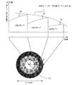
具体的な制御方法の例について図7を参照して説明する。
【0060】
この制御例では、制御の基準として、隣接するアクセスポイントAPでの干渉電力が一定以下になるように制御する。
隣接するアクセスポイントAPの受信する干渉電力は、図7の符号21で示されるように、距離の2.5〜3.5乗則で減衰する。アクセスポイントAPに近づくに従って干渉を与えにくくなり、その分だけ信号出力を出すことが可能となる。
【0061】
一方、例えば64QAM伝送を考えた場合、アクセスポイントAPに近いものは電力が少なくても減衰が少ないが、アクセスポイントAPから離れるほど減衰が大きくなるために出す必要のある出力は増えていく。端末MTにとって必要な出力の距離依存性のカーブを図中の符号22で示す。アクセスポイントAPからの距離が大きくなるに従って、必要な送信電力は増大する。このカーブ22と干渉から制限される上限カーブ28との交点までの距離(エリア)が、64QAMで通信できるエリアとなる(図下の円中の最も淡い色が付されたエリア25)。
【0062】
一方、次のエリアとして、さらにアクセスポイントAPでの受信電力が少なくて良い16QAMがある。この場合も同様に16QAMで通信できるエリアを決めることができる(図下の円中の中間の濃さの色が付されたエリア26)、同様にQPSKでも通信エリア(図下の円中の最も濃い色が付されたエリア27)を決めることができる。
【0063】
以上のように、セルには、変調レートで分けられるゾーンが画定される。このような制御を各サブキャリア単位で行うことにより、各サブキャリアが許容される出力の中で伝送できる最大の伝送レートを確保することができるようになる。
その結果、他セルへの干渉を抑制しつつ、必要な通信を行うことが可能となり、全体のスループットを向上させることができる。
【0064】
尚、端末位置の検出方法としては、受信した電波の遅延を用いる方法や、平均的な受信電力を基準にして求める方法を用いることができる。すなわち、TDMA無線通信システムでは、アクセスポイントAPにおいてスロットの管理を行っているため、近くに存在する端末からは早い時間のタイミングで信号が返ってくるのに対し、遠くに存在する端末の場合には遅延の影響が大きくなるため、遅いタイミングで信号が返ってくる。そこで、この時間を基準にセル内における端末の位置を判定、端末MTがどのゾーンに存在するかを知ることができる。
【0065】
そこで、図3に示したように、タイミング検出回路11−1、20−1内の遅延時間測定回路11−1a、21aにより、アクセスポイントAPと端末MTとの間の信号のやり取りにおける比較的長時間サンプリングして平均的な信号遅延時間を求め、それに基づきアクセスポイントAPと端末MTとの間の距離を測定又は推測することができる。
【0066】
一方、前述のようにOFDM方式においては、各サブキャリア自体は他のサブキャリアとは独立した関係にあり、時間的にはレイリー分布に応じた変動をしている。従って、時々刻々と様々な値を取るが、比較的長い時間範囲で全サブキャリアの平均電力を観察すると、距離の2.5乗則から3.5乗則に応じた減衰を示す。
【0067】
そこで、全サブキャリアの平均電力から、上記のようなゾーンを画定することもできる。全サブキャリアを平均化する時間については、システムで想定している端末MTの移動速度や、セル半径に応じて変化するため、例えば、電力の分散が数dBに落ち着く値として求めることができる。
【0068】
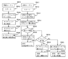
次に、本発明の第5の実施の形態による無線通信システムについて説明する。上記第1から第4までの実施の形態においては、ベストエフォートということで、変調方式と所要電力とを基準に選んでいる。ところで、システムによっては、最低限伝送に必要な容量が決められている場合がある。例えば、最小2Mbpsなどと、帯域保証が決められている場合もある。この場合の処理の流れを図8にフローチャート図で示す。
【0069】
本発明の第5の実施の形態においては、各サブキャリアの電力を測るとともに順位付けを行い、閾値を超えているサブキャリアの数で最小値を満たしている場合には、その閾値を超えたサブキャリアで送れる通信量を最大とする。一方、閾値を超えているサブキャリアの数で最小値を満たしていない場合には、電力の大きいほうから順に選択していき、閾値を下回っても必要となる最小伝送容量を送れるところまではサブキャリアを用いることにする。
以下、具体的に各ステップについて図8を参照して順に説明する。
【0070】
図8に示すように、まず、ステップS802で準備ルーチンS801を開始する。ステップS803で、ブロードキャストスロットを検出する。ステップS804で、サブキャリアの電力を測定する。測定された電力に基づいて、ステップS805で電力の大きい順にサブキャリアの順位付けを行う。ステップS806において、サブキャリアの閾値を比較し、64QAMで送ることができるサブキャリアの個数を算出する。
【0071】
一方、ステップS812において送信ルーチンS811をスタートする。ステップS813において、送信に必要なデータのビット数を算出する。ステップS814で、例えば64QAMで送信した場合に必要なサブキャリア数を算出する。64QAMでは、1サブキャリアは6ビットであるから、ビット数よりサブキャリア数を簡単に求めることができる。
【0072】
ステップS821において、ステップS806で算出したサブキャリア数と、ステップS814で算出したサブキャリア数とを比較する。ステップS806で算出したサブキャリア数が、ステップS814で算出したサブキャリア数より多い場合には、64QAMで全てのサブキャリアを送信することが可能であるため、ステップS822においてサブキャリアを全て64QAM送信に振り分け、ステップS823において64QAMのみで送信を行う。
【0073】
ステップS821において、ステップS806で算出したサブキャリア数が、ステップS814で算出したサブキャリア数よりも少ない場合には、64QAMで全てのサブキャリアを送信することはできないため、ステップS824において不足分を、予め受信電力に基づいて付した順位に従い16QAMに割り当て、ステップS825において64QAMと16QAMとで送信を行う。
【0074】
すなわち、ステップS806で求めた閾値を満たしていないサブキャリアは、必然的に変調方式の多値数を小さくする必要があるので、その分は、次の閾値(例えば、64QAMから16QAMに変更する)を設定値として用いる。
また、このときに図5(A)に示した出力制限を行うことにより、受信電力の大きさに関する順位の高いサブキャリアは出力を絞ることができ、帯域保証を確保しながら、他局への干渉を絞ることができる。
【0075】
次に、本発明の第5の実施の形態の変形例による無線通信システムについて、図9を参照して説明する。本変形例による無線通信システムは、閾値を満足していても、意識的に信号を送信しないように制御する。
例えば、インターネットのように信号情報量が非対称の場合(送信と受信のデータ量が異なるなどの場合)には、信号によっては、ACK(Acknouwledgement)、NAK(Negative Acknowledgement)等、移動局から基地局までの上りチャネル(UPLINK)に、わずかなビット数を送るだけでよいものもある。このような場合に、不必要なサブキャリアの伝送を止めることにより干渉量を減らすことも可能である。
【0076】
この場合も、予め電力に応じて順位付けしたデータを用いて伝播特性の良い順番に必要な数のみサブキャリア送り、残りのサブキャリアについては送信しないように制御を行う。これにより、より一層、干渉を減らすことができる。また、サブキャリアの別の選び方として、伝播特性のみで選ばずに、用いるサブキャリアの優先順位を端末MT毎に決めておき、その中から電力の順位付けを行うことも可能である。
【0077】
伝播特性だけで順位付けした場合、それぞれの端末MTが同じ伝播状況になることはあまり考えられないが、それでも、独立に測定し順位付けした項目だけで通信すると、制約がないため特定のサブキャリアを多くの端末MTが使ってしまう可能性も無視できない。
そこで、端末MT毎に、伝播路順位付けとアクセスポイントAPの指示や生産時に割り振られる優先サブキャリア情報を用いることで、すべての端末MTが同一サブキャリアを選んでしまうことを回避することができる。
【0078】
この場合、閾値を超えていると判定されているサブキャリアと、必要な伝送量が、割当て制限で割り当てられたサブキャリア内にある場合には、その範囲で通信を終了するが、割り当て制限内で納まらないときには、第2位の割当てサブキャリアを用いて通信を行う。
かかる制御方法について図9を参照して説明する。
【0079】
図9に示すように、まず、ステップS902で準備ルーチンS901を開始する。ステップS903で、ブロードキャストスロットを検出する。ステップS904で、サブキャリアの電力を測定する。測定された電力に基づいて、ステップS905で電力の大きい順にサブキャリアの順位付けを行う。ステップS906において、サブキャリアの閾値を比較し、64QAMで送ることができるサブキャリアの個数を算出する。
【0080】
一方、ステップS912において送信ルーチンS911をスタートする。ステップS913において、送信に必要なデータのビット数を算出する。ステップS914で、例えば64QAMで送信した場合に必要なサブキャリア数を算出する。
【0081】
ステップS915において、サブキャリアの割当て制限を行うか否かを判断する。サブキャリアの割当て制限を行わない場合には、ステップS916に進み、順位の高いサブキャリアから割当てを行う。ステップS917において、64QAMのみで送信を行う。尚、データ量が少ない場合を想定すると、図8に示すステップS821の判断ステップを省略することができる。
【0082】
ステップS915においてグループ化されたサブキャリアの割当て制限を行う場合には、ステップS918に進む。ステップS918において、以下に詳細に説明するようにサブキャリア数の比較を行う。グループ化された1グループ内でサブキャリアの割り当てが足りれば、ステップS919でサブキャリアの振り分けを行い、ステップS920において第1制限にみにより送信を行う。
【0083】
ステップS918において、グループ化された1グループ内でサブキャリアの割り当てが足りなければ、ステップS921に進み、第2位割当てサブキャリアに振り分け、ステップS922において第1及び第2の制限に基づいて送信を行う。
【0084】
以上のステップ、特にグループ分けの思想を具体的に説明すると、例えば、全サブキャリア数を128とし、32サブキャリア毎にグループ化し、4グループまであるものとし、端末MT毎に優先順位を設定する。
準備ルーチンで、128のサブキャリアのうち60のサブキャリアが閾値を越え、多値通信可能であるとして準備されている。
【0085】
この状態で送信信号として、5サブキャリア相当のデータが送信必要な場合、自端末MTに割り当てられた第1優先32サブキャリア中に、前記60サブキャリアの中の5サブキャリアがあれば、それで送信を行う。しかしながら、その中に閾値を超えているサブキャリアが5未満であった場合には、第2優先のサブキャリアを使うことになる。
このように制御することで、簡易的に周波数分割の効果が得られ、帯域内の電力の均一化に有効な場合がある。
【0086】
以上のように、本発明の各実施の形態による無線通信システムにおいては、他局への干渉を最小限に抑えることができ、TDMAを用いた1セル周波数繰り返しシステムの問題点であった回線容量を多く取ることができるようになる。これは、時間分割したTDMAのタイムスロットをOFDMのサブキャリアレベルで制御することで、周波数軸上での干渉波抑圧することにより、統計的な雑音量を下げることができるためである。また、このときには、伝送情報1ビットに対する干渉電力を最低にできる。
【0087】
また、本発明の実施の形態による無線通信システムでは、セルにおける端末の位置関係、つまり隣接セルに与える影響を考慮し、送信出力と多値変調方式を制御することで、端末の場所に関わらず、隣接セルに対する干渉を一定化でき、干渉抑圧が可能になる。
【0088】
また、全サブキャリアを閾値で2値判定するだけではなく、順位付けすることで、送信データの所要量が最大多値数のみで送れない場合や、送信データが少ない場合にも効率よく、干渉の少ない状態で送ることができるようになる。
また、測定結果を相手に通知する手段を用いることで、サブキャリア制御の基準を個別に持つことができるので、受信電力(C)のみではなく、干渉電力との比(C/I)での制御や、送信と受信の周波数が異なる場合にも、本発明の実施の形態による無線通信システムを用いることができ、回線容量の向上をはかることが出きるようになる。
尚、多値数の代わりに符号化率を用いて変調しても良い。
【0089】
以上、実施の形態に沿って本発明を説明したが、本発明はこれらに制限されるものではない。その他、種々の変更、改良、組み合わせが可能なことは当業者に自明であろう。
本明細書に記載されている発明は、特許請求の範囲に記載されているそれぞれの発明に加えて、少なくとも以下の付記に記載されている発明を含むものとする。
【0090】
(付記1)一方の無線局、例えば基地局が設定した端末局の伝送レート以上の複数の伝送レートをサポートしている場合に、基地局では端末局から返信されてきたサブキャリア毎の受信状況に応じて、設定以上の複数種類の変調方式、符号化率を用いてサブキャリア毎の伝送レートを複数コントロールすることを特徴とするTDMA無線通信システム。
【0091】
(付記2)無線局(通信機)がサポートできる最大伝送レート、所望の受信電力に関して、一方の通信機から他方の通信機に伝送することを特徴とするTDMA無線通信システム。
【0092】
(付記3)複数サブキャリア変調方式を用い、少なくとも第1及び第2の無線局を有するTDMA無線通信システムに用いるのに適しており、
前記第2の無線局は、前記第1の無線局のサブキャリア毎の受信状況に基づき、前記第1の無線局において一定値以上の伝送レートを得ることができるサブキャリアのみを選択し、かつ、選択されたサブキャリアをその受信状況に応じた多値数又は符号化率により変調して通信を行うことを特徴とした第2の無線局。
【0093】
(付記4)複数サブキャリア変調方式を用い、少なくとも第1及び第2の無線局を有するTDMA無線通信システムに用いるのに適しており、サブキャリア毎の受信電力を検知するサブキャリア電力検出手段と、該サブキャリア電力検出手段により検知された前記受信電力に関する情報を前記第2の無線局に通知する通知手段とを有する第1の無線局。
【0094】
(付記5)複数サブキャリア変調方式を用い、少なくとも第1及び第2の無線局を有するTDMA無線通信システムに用いるのに適しており、前記第1の無線局から送られたサブキャリア毎の受信状況に基づき、前記第1の無線局において一定値以上の伝送レートで通信可能な受信電力が得られるサブキャリアであるか否かを判別する判別手段と、該判別手段により通信可能と判別されたサブキャリアのみを選択する送信サブキャリア選択手段とを含み、該送信サブキャリア選択手段により選択されたサブキャリアをその受信状況に応じた多値数又は符号化率により変調して通信を行うことを特徴とした第2の無線局。
【0095】
(付記6)複数サブキャリア変調方式を用い、互いに同じ周波数を用いて通信を行う少なくとも1つの基地局と端末局とを有するTDMA無線通信システムに用いるのに適しており、サブキャリア毎の受信電力を検出するサブキャリア電力検出手段と、該サブキャリア電力検出手段により検出された受信電力に基づいて、前記端末局において一定値以上の伝送レートで通信可能な受信電力が得られるサブキャリアであるか否かを判別する判別手段と、該判別手段により通信可能と判別されたサブキャリアのみを選択的する送信サブキャリア選択手段とを含み、該送信サブキャリア選択手段により選択された各サブキャリアをその受信電力に応じた多値数又は符号化率により変調して通信を行うことを特徴とした基地局。
【0096】
(付記7)複数サブキャリア変調方式を用い、少なくとも1つの基地局と端末局とを有するTDMA無線通信システムに用いるのに適しており、前記端末局のサブキャリア毎の受信状況に基づき、前記端末局において一定値以上の伝送レートを得ることができるサブキャリアのみを選択し、かつ、選択されたサブキャリアをその受信状況と前記基地局を基準とした前記端末局の位置とに応じて割当てられる多値数又は符号化率により変調して通信を行うことを特徴とした基地局。
【0097】
(付記8)複数サブキャリア変調方式を用い、少なくとも1つの基地局と端末局とを有するTDMA無線通信システムに用いるのに適しており、サブキャリア毎の受信電力を検知するサブキャリア電力検出手段と、該サブキャリア電力検出手段により検知された前記受信電力に関する情報を前記基地局に通知する通知手段とを有する端末局。
【0098】
(付記9)複数サブキャリア変調方式を用い、少なくとも1つの基地局と端末局とを有するTDMA無線通信システムに用いるのに適しており、前記端末局から送られたサブキャリア毎の受信状況に基づき、前記端末局において一定値以上の伝送レートで通信可能な受信電力が得られるサブキャリアであるか否かを判別する判別手段と、前記受信状況と前記基地局を基準とした前記端末局の位置とに応じて多値数又は符号化率を割当てる割当て手段と、該判別手段により通信可能と判別されたサブキャリアのみを選択的に、かつ、前記割当て手段により割当てられた多値数又は符号化率により送信するサブキャリアを選択する送信サブキャリア選択手段とを有する基地局。
【0099】
(付記10)複数サブキャリア変調方式を用い、互いに同じ周波数を用いて通信を行う少なくとも1つの基地局と端末局とを有するTDMA無線通信システムに用いるのに適しており、前記端末局のサブキャリア毎の受信状況に基づき、前記端末局において一定値以上の伝送レートを得ることができるサブキャリアのみを選択し、かつ、選択されたサブキャリアをその受信状況と前記基地局を基準とした前記端末局の位置とに応じて割当てられる多値数又は符号化率により変調して通信を行うことを特徴とした基地局。
【0100】
(付記11)複数サブキャリア変調方式を用い、互いに同じ周波数を用いて通信を行う少なくとも1つの基地局と端末局とを有するTDMA無線通信システムに用いるのに適しており、サブキャリア毎の受信電力を検出するサブキャリア電力検出手段と、該サブキャリア電力検出手段により検出された受信電力に基づいて、前記端末局において一定値以上の伝送レートで通信可能な受信電力が得られるサブキャリアであるか否かを判別する判別手段と、前記受信電力と前記基地局を基準とした前記端末局の位置とに応じて多値数又は符号化率を各サブキャリアに対して割当てる割当て手段と、前記判別手段により通信可能と判別されたサブキャリアのみを選択的に、かつ、前記割当て手段により割当てられた多値数又は符号化率で送信する送信サブキャリア選択手段とを有する基地局。
【0101】
【発明の効果】
以上のように、本発明を用いることによって、他局への干渉を最小限に抑えることができ、TDMAを用いた1セル周波数繰り返しシステムの問題点であった回線容量について、多く取ることができるようになる。
【0102】
また、セルにおけるMTの位置関係、つまり隣接セルに与える影響を考慮し、送信出力と多値変調方式を制御することで、MTの場所に関わらず、隣接セルに対する干渉を一定化でき、干渉抑圧が可能になる。
さらに、全サブキャリアを電力に基づいて順位付けすることで、送信データの所要量が最大多値数のみでおくれない場合や、送信データが少ない場合にも効率よく、干渉の少ない状態で送ることができる。
【図面の簡単な説明】
【図1】 本発明の実施の形態による無線通信システムにおけるTDMA−OFDM方式のタイムスロットの割当てを示す図である。
【図2】 図2(A)及び(B)は、本発明の実施の形態による無線通信システムにおけるサブキャリアがフェージング等の影響により歪む様子を示す電力スペクトル図である。
【図3】 図3(A)は、本発明の実施の形態による無線通信システムにおける端末の構成を示す機能ブロック図であり、図3(B)は、本発明の実施の形態による無線通信システムにおけるアクセスポイントの構成を示す機能ブロック図であり、図3(C)は、ブロードキャストパケットを含む信号の繰り返し周期を示す図である。
【図4】 図4(A)及び(B)は、本発明の実施の形態による無線通信システムにおけるサブキャリアがフェージング等の影響により歪む様子を示す電力スペクトル図であり、図4(A)は送信スペクトル、図4(B)は受信スペクトル図である。
【図5】 図5(A)は、図4(B)に示す送信スペクトルを所定の受信電力値P1に調整する様子を示す図であり、図5(B)は、調整後の受信スペクトルを示す図である。
【図6】 図6(A)は、本発明の他の実施の形態による無線通信システムによるアクセスポイントの構成を示す機能ブロック図であり、図6(B)は、情報信号を含む信号の繰り返し周期を示す図である。
【図7】 本発明の実施の形態による無線通信システムであって、TDD方式を用いた場合のアクセスポイントの制御の様子を示す図である。
【図8】 本発明の他の実施の形態による無線通信システムによる送信側の処理を示すフローチャート図である。
【図9】 本発明の他の実施の形態による無線通信システムによる送信側の処理を示すフローチャート図である。
【図10】 セルラーシステムの一般的な概念を示す図である。
【図11】 図11(A)はFDMA方式、図11(B)はTDMA方式による周波数の利用法を示す図である。
【図12】 TDMAシステムにおけるタイムスロットの使い方を説明するための図である。
【符号の説明】
TS…タイムスロット、MT…端末、AP…アクセスポイント、2…OFDMシンボル、3,6,13,16…フィルタ、4,14…FFT、5,15…復調器、7、17…IFFT、8…変調器、9…ブロードキャスト検出部、10…サブキャリア電力検出回路、11,20…MAC層、11−1…タイミング抽出回路、11−1a…遅延時間測定回路、12…記憶手段、19…送信サブキャリア選択回路、20−1…タイミング抽出回路、20−2…算出回路、21…判別回路、34…検知情報検出部、35…送信サブキャリア選択回路。[0001]
BACKGROUND OF THE INVENTION
The present invention provides a cellular system that has a service area in a plane or line, divides the service area into small sections (cells), and establishes a base station for each cell to communicate with terminals in the cell. The present invention relates to a wireless communication system that enables high-speed and stable communication when a cell is configured by using.
[0002]
[Prior art]
In wireless systems such as mobile phones, it is necessary to cover the communication area, and the reach of radio waves is limited, and a single base station cannot cover the entire service area. A station (access point: hereinafter referred to as “access point AP”) is provided so that communication can be continued even if the terminal station moves. For example, a system having a cell configuration as shown in FIG. 10 is used.
[0003]
As shown in FIG. 10, a large number of substantially
[0004]
In such a configuration, even if the terminal MT40 moves, the
[0005]
However, in the above configuration using the FDMA system, the frequency that can actually be used in one
[0006]
Therefore, a proposal has been made to configure cells at the same frequency using a TDMA (Time Division Multiple Access) method. A frequency and time sharing method in the TDMA system will be described with reference to FIG. 11 shows time on the horizontal axis and frequency on the vertical axis, FIG. 11A shows a frequency utilization method for the FDMA system, and FIG. 11B shows a frequency usage method for the TDMA system.
[0007]
As shown in FIG. 11A, in the FDMA system, different frequencies from f1 to f8, for example, are assigned to each user, so that the user occupies the same frequency on the time axis for communication. In addition, since there are a plurality of users in one cell, a plurality of frequency channels are assigned to each cell.
[0008]
As shown in FIG. 11B, in the TDMA system, the frequency band used is one, and is divided into fine slots (time slots) on the time axis, and the user uses one of the slots. Communicate. However, in order to continue communication, it is necessary to repeatedly assign a slot to each user, and a slot is assigned to a user for each period, with the illustrated repetition period being one cycle.
[0009]
In the TDMA scheme, how to use time slots when there are two or more access point APs, for example, access point AP1 and access point AP2, will be described with reference to FIG. FIG. 12 shows a system having eight time slots TS1 to TS8.
[0010]
It is assumed that the two access points AP1 and AP2 operate in the TDMA wireless communication system and have the same number of time slots (repetition period) and time slot time (time width of one time slot). In addition, the time slot time is assumed to be synchronized.
[0011]
As shown in FIG. 12, communication is performed using the second time slot TS2 between the first access point AP1 and the terminal (MT: not shown). Accordingly, seven time slots from TS1, TS3 to 8 are vacant as time slots. When communication between the second access point AP2 and the terminal is performed in the time slot TS2, the interference is large, and therefore communication is performed using any one of the seven time slots from TS1 and TS3 to TS8. Thus, by using the same frequency and dividing in the time domain, frequency sharing between different access points AP can be performed.
[0012]
In the frequency division method (FDMA), it is difficult to freely change the frequency width due to limitations of analog circuits such as filters. However, in the TDMA method, slots are divided on the time axis, so circuit restrictions are imposed. Less is. Therefore, the time slots that can be used by one terminal are not limited to one time slot, and two or three time slots can also be used. In this case, the communication capacity can be doubled or tripled, and the bandwidth can be freely controlled for multimedia communication. As described above, the TDMA method is an advantageous communication method for packet data communication or the like in which the transmission capacity constantly changes.
[0013]
In addition, power control can be given as an additional technique for realizing a TDMA wireless communication system. The terminal may exist from the center of the cell to the end of the cell (cell edge). However, due to the nature of the radio wave, there is little propagation attenuation in communication between the access point and the terminal in the cell center. In communication, the attenuation becomes large.
[0014]
On the other hand, the quality required for communication is fixed, so there is no need to set the same transmission level. The signal power is kept constant by reducing the transmission power at the cell center and increasing the transmission power at the cell edge. By maintaining it, unnecessary radio wave emissions can be reduced. When a cell is configured with such a system, it is possible to suppress interference not only between adjacent cells that are generally paying for the influence of interference but also adjacent cells (adjacent adjacent cells). .
[0015]
[Problems to be solved by the invention]
When a cell is configured by the system as described above, the number of time slots as the minimum unit and power control by power control greatly affect the number of terminals (MT) that can be accommodated in the cell.
When cells are assembled at the same frequency, the frequency is shared by each access point AP, and therefore the number of interferences from other stations can be accommodated. In particular, by performing power control as described above, radiation from the MT at the cell center can be suppressed. The terminal MT present at the cell edge can obtain the required received power. However, interference with other cells also increases as power (power) is increased at the terminal MT existing at the cell edge.
[0016]
In order to eliminate such problems, it is necessary to reduce interference as much as possible. However, attenuation due to propagation is physically determined, so that stable reception is performed and interference power is minimized. Is a trade-off relationship. In addition, when the interference is large, especially when interference power greater than the allowable power is in all the time slots, the signal radio wave between the access point AP and the terminal MT becomes busy and communication becomes impossible. There was also a problem.
An object of the present invention is to provide a TDMA wireless communication technique capable of ensuring stable communication (reception) while suppressing interference.
[0017]
[Means for Solving the Problems]
According to an aspect of the present invention, there is provided a TDMA radio communication system using a plurality of subcarrier modulation schemes and having at least first and second radio stations, wherein the second radio station is the first radio station. Based on the reception status of each subcarrier, only the subcarrier that can obtain a transmission rate of a certain value or higher is selected in the first radio station, and the selected subcarrier is selected according to the reception status. There is provided a TDMA wireless communication system characterized in that communication is performed by modulation according to the number of values or the coding rate.
[0018]
A TDMA radio communication system using a plurality of subcarrier modulation schemes and having at least first and second radio stations, wherein the first radio station detects subcarrier power detection for each subcarrier. Means and a notification means for notifying the second radio station of information relating to the received power detected by the subcarrier power detection means, wherein the second radio station receives information from the first radio station. A discriminating means for discriminating whether or not the first radio station is a subcarrier capable of obtaining a reception power communicable at a transmission rate equal to or higher than a predetermined value, based on the reception status of each subcarrier transmitted; Transmitting subcarrier selecting means for selecting only subcarriers determined to be communicable by the means, and receiving the subcarriers selected by the transmitting subcarrier selecting means. TDMA wireless communication system and performing modulation on communication is provided by the multi-level number or encoding rate according to the situation.
[0019]
In the TDMA wireless communication system, the first wireless station does not transmit subcarriers that cannot be received at a transmission rate higher than a certain value, and transmits only subcarriers that can be communicated according to the reception status. In addition, since transmission is performed with a multi-value number or a coding rate, the influence of interference can be reduced while ensuring reception power.
[0020]
A TDMA wireless communication system having at least one base station and a terminal station that perform communication using the same frequency using a plurality of subcarrier modulation schemes, wherein the terminal station broadcasts the received power of subcarriers. Notification means for notifying the base station of information, the base station detecting means for detecting broadcast information, and subcarrier power detection for detecting received power for each subcarrier according to the broadcast information And determining means for determining whether or not the terminal station is a subcarrier capable of obtaining received power communicable at a transmission rate equal to or higher than a predetermined value based on the received power detected by the subcarrier power detecting means. And selectively transmitting only the subcarriers determined to be communicable by the determining means A TDMA wireless communication system comprising: a subcarrier selecting means for performing communication by modulating each subcarrier selected by the transmission subcarrier selecting means with a multi-value number or a coding rate according to the received power Is provided.
[0021]
According to the TDMA radio communication system, the terminal station does not need to detect the reception power for each subcarrier, and the base station may detect it.
According to another aspect of the present invention, there is provided a TDMA wireless communication system using a plurality of subcarrier modulation schemes and having at least one base station and a terminal station, wherein the base station is provided for each subcarrier of the terminal station. Based on the reception status, the terminal station selects only subcarriers that can obtain a transmission rate of a certain value or higher, and the selected subcarrier is selected based on the reception status and the base station. There is provided a TDMA wireless communication system characterized in that communication is performed by modulation according to a multi-value number or a coding rate assigned in accordance with a position.
[0022]
According to the TDMA wireless communication system, it is possible to perform good wireless communication while suppressing interference by balancing the received power that changes depending on the position of the terminal station and the interference power.
Also, a TDMA wireless communication system that uses a plurality of subcarrier modulation schemes and has at least one base station and a terminal station, wherein the terminal station includes subcarrier power detection means for detecting received power for each subcarrier; Notification means for notifying the base station of information related to the received power detected by the subcarrier power detection means, the base station based on the reception status of each subcarrier sent from the terminal station, Discriminating means for discriminating whether or not the terminal station is a subcarrier capable of obtaining received power that can be communicated at a transmission rate equal to or higher than a certain value; and the reception status and the position of the terminal station with reference to the base station; An allocation unit that allocates a multi-value number or a coding rate according to each of the subcarriers that are determined to be communicable by the determination unit, and the allocation unit TDMA radio communication system having a transmission subcarrier selection section that selects a subcarrier to be transmitted by the multi-level number or encoding rate assigned by is provided.
A reception power / interference power ratio can be increased by assigning a multi-value number or a coding rate according to the reception status and the position of the terminal station with reference to the base station.
[0023]
Preferably, the transmission rate equal to or higher than the predetermined value is a maximum transmission rate. By setting so as to obtain the maximum transmission rate, the performance of the wireless communication system can be maximized. The maximum transmission rate that can be demodulated may be detected by, for example, one radio station, for example, a base station.
In the above solution, each component, for example, the first radio station and the second radio station, the base station, and the terminal station may exist independently. Even in that case, it shall fall under the category of the present invention.
[0024]
DETAILED DESCRIPTION OF THE INVENTION
Similar to a general TDMA wireless communication system, the TDMA wireless communication system in this specification also includes a service area formed by a large number of cells each including at least one access point and a terminal. Shall.
Before describing embodiments of the present invention, considerations made by the inventors will be described with reference to the drawings.
[0025]
First, in a TDMA wireless communication system using 1-cell repetition, as shown in FIG. 1, the time width of each time slot is set to an integral multiple of the time width of an Orthogonal Frequency Division Multiplexing (OFDM) slot. To do. An OFDM slot is a minimum unit of OFDM, and is a time width determined from the transmission rate of an OFDM signal composed of a plurality (tens to thousands) of subcarriers and the time corresponding to a guard interval. Have.
[0026]
As shown in FIG. 1, the frequency is divided into a plurality of time slots according to the TDMA scheme, for example, TS1 to 8. In addition, each time slot TS is composed of a plurality (6 in FIG. 1) of
[0027]
Next, the OFDM signal will be described. The OFDM signal is composed of a plurality of modulated signals called subcarriers. Since each subcarrier transmits independent signals in an orthogonal relationship, there is no correlation between the subcarriers and each can be treated as independent.
[0028]
FIG. 2 is a diagram showing a signal spectrum in which the horizontal axis represents frequency and the vertical axis represents power. As shown in FIG. 2 (A), the transmission signal modulated by the OFDM method does not have frequency dependence on the maximum power. On the other hand, as shown in FIG. 2B, the received power is influenced by the reflected wave or the like in the propagation path and shows frequency dependence on the maximum power. As shown in FIG. 2 (B), a phenomenon in which the influence received for each frequency is different is called a frequency selective fading phenomenon. When a signal is subjected to frequency selective fading, subcarriers with low received power have a low received signal-to-noise ratio (C / N) and a large number of errors. Therefore, the subcarrier signal having a large C / N is not affected.
[0029]
In addition, since each of the subcarriers is orthogonal, a different modulation scheme can be applied to each subcarrier. For example, different sub-carrier modulation schemes such as BPSK (Binary Phase Shift Keying), QPSK, 16QAM, and 64QAM can be applied.
[0030]
In a general adaptive modulation system, communication is performed at 64 CAM, for example, at a high C / N, and communication is performed at, for example, BPSK, at a low C / N so that stable communication can be performed even under such frequency selective fading. Something like that has been done.
[0031]
The inventor uses the TDMA-OFDM wireless communication system, calculates the reception power of each subcarrier from the received signal, and has a lot of information in the time slot at a frequency (band) with a large reception power. The inventors have come up with a technique for performing control so that transmission is performed with a modulation method having a large degree of multi-value (number of multi-values), while transmission is not performed at a frequency (band) with low reception power.
Hereinafter, based on the above consideration, a wireless communication system according to an embodiment of the present invention will be described with reference to the drawings.
[0032]
FIG. 3 is a functional block diagram illustrating a configuration example of the wireless communication system according to the first embodiment of the present invention. FIG. 3A illustrates a configuration example on the terminal side, and FIG. 3B illustrates a configuration example on the access point AP side. It is. FIG. 3C is a conceptual diagram showing a repetitive periodic structure in a time slot.
[0033]
As shown in FIG. 3 (A), the terminal MT, in order from the reception side to the transmission side, receives
[0034]
As shown in FIG. 3B, the access point AP, in order from the receiving side to the transmitting side, receives-
When a terminal MT enters a cell including a certain access point AP, first, information is exchanged at least once between the access point AP and the terminal MT. For example, the terminal MT ID, function, etc. Registered in the access point AP.
[0035]
Next, as shown in FIG. 3C, the access point AP periodically transmits a broadcast signal (packet) using one of the time slots. This broadcast packet has a broadcasting (broadcast) role to all terminals, is a signal received by all terminals MT in common, and is transmitted in the most reliable scheme as a modulation scheme. For example, the broadcast packet includes an identification number of the access point AP, information on a supported system, and the like.
[0036]
On the receiving terminal side, the
[0037]
In the access point AP, a signal transmitted from the terminal MT side that enters the cell is received, and from the received signal, the
[0038]
The delay time measurement circuits 11-1a and 21a measure the distance between the access point AP and the terminal MT as described later by measuring the delay time in the exchange of signals between the access point AP and the terminal MT. Or guess.
As will be described later, the calculation circuit 20-2 calculates the transmission rate at each position such that the interference power to the adjacent cell is a certain value or less.
[0039]
As shown in FIG. 2, even if all the subcarriers are transmitted with the same power on the transmission side, fading occurs due to the positional relationship of the reception system, and there are subcarriers with large received power and small subcarriers. In such a case, for example, when trying to communicate without error using all subcarriers, a method such as the above-described adaptive modulation is used, and a subcarrier having a good reception state is sent as a high multilevel signal such as 64QAM, A subcarrier having a poor reception state is transmitted by a low multilevel signal such as BPSK.
[0040]
By the way, a subcarrier with a poor reception state is a subcarrier with low reception power for the terminal, but this is due to a large loss in the propagation path, and transmission is performed as shown in FIG. The signals themselves are output evenly. Therefore, an interference signal with a low level is not sent to other terminals or other cells, and may be stronger on the contrary. In short, if considered statistically, the average interference signal strength of all the subcarriers is the same.
[0041]
In other words, the signal itself that can be transmitted falls to a fraction (1/6 for BPSK 1 bit compared to 6 bits for 64QAM) due to the use of BPSK or the like, but the same is true for interference with other stations. Therefore, the amount of interference noise to other terminals MT per bit is several times.
[0042]
On the other hand, when the radio communication system according to the present embodiment is used, subcarriers having a poor propagation environment (reception power is low) are not transmitted, so that the interference level per bit can be minimized.
Thus, in a TDMA-OFDM wireless communication system, the amount of interference given to other stations during 1-bit transmission is minimized by setting the time slot to an integral multiple of the OFDM slot and controlling the subcarriers to be transmitted. Can do.
[0043]
FIG. 4A shows the spectrum of the transmission signal, and FIG. 4B shows the spectrum of the reception signal. 4A is a diagram corresponding to FIG. 2A, and FIG. 4B is a diagram corresponding to FIG. 2B. From FIG. 2 (A) and FIG. 2 (B), as shown in FIG. 4 (A) in all the subcarriers, only the subcarrier that can obtain the received power that can be communicated at the maximum transmission rate supported by the terminal MT. Since transmission is performed in the used frequency bands f1, f2, and f3 and transmission is not performed in other frequency bands, a value equal to or higher than a predetermined value can be obtained as reception power even in the reception spectrum shown in FIG. 4B.
[0044]
Considering only the own station, the transmission amount seems to have dropped, but when considering the entire wireless communication system having a planar cell arrangement, the throughput of the entire wireless communication system is determined by the total amount of interference, so 1-bit transmission By minimizing the interference caused by the above, the throughput of the entire wireless communication system can be improved and communication traffic can be improved.
[0045]
In a conventional single-carrier TDMA wireless communication system different from the OFDM system, even though the modulation degree can be changed, the local station cannot communicate, so transmission cannot be turned on / off according to propagation characteristics. On the other hand, in the radio communication system according to the present embodiment, for example, as a result of processing in the
[0046]
Next, the radio | wireless communications system by the 2nd Embodiment of this invention is demonstrated with reference to drawings. In the wireless communication system according to the first embodiment of the present invention, only subcarriers that can perform multi-value transmission at the received level are selected and transmitted. In the radio communication system according to the present embodiment, power control is further performed for each subcarrier.
[0047]
In the wireless communication system according to the first embodiment of the present invention, when the received power of the selected subcarrier is viewed, the minimum power (required minimum power) that the subcarrier having the minimum received power needs for multi-level modulation. And the remaining subcarriers may still be too strong. Therefore, in the radio communication system according to the present embodiment, the transmission power is controlled so that the reception power on the reception side becomes the required minimum power.
[0048]
Specifically, the broadband subcarrier power is measured by the subcarrier
Actually, since a predetermined margin is necessary to absorb the difference in system between transmission and reception, it is necessary to set it so that it falls within the power range obtained by adding the system margin at the time of system design to the required power. preferable.
The transmission spectrum and reception spectrum controlled in this way are shown in FIG. 5 (A) and FIG. 5 (B).
[0049]
As shown in FIG. 5A, the reception power of each subcarrier in the frequency bands f11, f12, and f13 in which transmission is performed is reduced to the required power P1 as indicated by an arrow. Therefore, on the receiving side, subcarriers having substantially the same reception level are received, and subcarriers in frequency bands other than the frequency bands f11 ′, f12 ′, and f13 ′ are not transmitted / received. As a result, in addition to the case of the wireless communication system according to the first embodiment of the present invention, the necessary power can be reduced, and the influence of interference can be further reduced.
[0050]
In the radio communication system according to the second embodiment of the present invention, considering the margin of the radio communication system, all subcarriers that can obtain only received power equal to or less than the required power are excluded from transmission targets. In actuality, subcarriers for which the reception power is slightly insufficient may be transmitted with slightly higher power. In this case, communication efficiency may be improved. In particular, in the case of a radio communication system with a sufficient transmission capability (maximum output capability), it is possible to increase the power of subcarriers. Also in this case, for example, the adjustment circuit 18a shown in FIG. Next, the radio | wireless communications system by the 3rd Embodiment of this invention is demonstrated with reference to FIG. The radio communication system according to the present embodiment is an example applied to a TDD (Time Division Duplex) system.
[0051]
As shown in FIG. 6 (A), the radio communication system (access point AP side) according to the present embodiment, in order from the reception side to the transmission side, receives
[0052]
As shown in FIG. 6B, the access point AP periodically transmits an information signal using one of the time slots. This information signal has a role of broadcasting to all terminals, is a signal received by all terminals MT in common, and is transmitted by the most reliable modulation method.
[0053]
The access point AP receives an information signal or the like from the terminal MT, measures the signal power of each subcarrier from the received signal by the subcarrier
[0054]
Based on the information signal, the access point AP determines a subcarrier to be transmitted by itself, and the transmission
[0055]
In the TDD system, the propagation characteristics received by the access point AP and the propagation characteristics to the terminal MT are almost the same. Therefore, the subcarrier to be used can be selected only by the access point AP without measuring the terminal MT and notifying the access point AP of the result. That is, unlike other systems, the TDD system has the same uplink and downlink communication frequencies in the communication between the access point AP and the terminal MT. In a system other than the TDD system, the access point AP needs to receive information on the reception power of each subcarrier from the terminal MT. On the other hand, when the TDD system is used, the access point AP displays information on the terminal MT. There is no need to detect.
Therefore, there is no need to measure the subcarrier signal on the terminal MT side, and there is an advantage that the terminal MT side can be reduced in size and price.
[0056]
Next, the radio | wireless communications system by the 4th Embodiment of this invention is demonstrated with reference to drawings.
In the wireless communication system according to the first to third embodiments, transmission is limited so that the carrier transmission rate is maximized.
[0057]
By the way, since a terminal existing at a cell edge is close to another cell, interference with an adjacent cell increases when a large amount of power is output. Therefore, it is preferable to select a terminal having a small required C / N so that power can be consciously reduced for terminals existing in the vicinity of adjacent cells. Since the power required for reception differs depending on the system, the absolute value cannot be defined. For example, the power required for 64QAM demodulation and the power required for QPSK demodulation may differ by 10 times or more.
[0058]
On the other hand, in non-line-of-sight communication in which a shadow of a signal is caused by an obstacle or the like, the signal strength is attenuated by the 2.5th power to the third power of the distance, and thus, for example, the terminal MT present near the access point AP Even if a signal is output, the signal intensity reaching the adjacent cell falls to a fraction of that, and there are few problems. However, the terminal MT at the cell edge tends to be an interference source because it is in close contact with an adjacent cell.
Further, since the terminal MT at the cell edge has a large distance to the access point AP, if the access point AP receives the same required power, the output will inevitably increase.
[0059]
Therefore, it is preferable to perform output control based on 64QAM or the like when the terminal MT exists in the vicinity of the cell center, and to control output based on a modulation scheme such as QPSK when the terminal MT exists at the cell edge.
An example of a specific control method will be described with reference to FIG.
[0060]
In this control example, as a reference for control, control is performed so that the interference power at the adjacent access point AP becomes a certain level or less.
The interference power received by the adjacent access point AP is attenuated by the 2.5 to 3.5 power law of the distance, as indicated by reference numeral 21 in FIG. As the access point AP is approached, interference is less likely to occur, and signal output can be output accordingly.
[0061]
On the other hand, for example, in the case of 64QAM transmission, attenuation close to the access point AP is small even if the power is small, but the output increases because the attenuation increases as the distance from the access point AP increases. A distance dependence curve of the output necessary for the terminal MT is indicated by reference numeral 22 in the figure. The required transmission power increases as the distance from the access point AP increases. The distance (area) to the intersection of the curve 22 and the
[0062]
On the other hand, as the next area, there is 16QAM in which the reception power at the access point AP may be further reduced. In this case as well, the area that can be communicated by 16QAM can be determined (area 26 with a medium dark color in the circle at the bottom of the figure). Similarly, the communication area (most of the circles at the bottom of the figure is also represented by QPSK). An area 27) with a dark color can be determined.
[0063]
As described above, zones that are divided by the modulation rate are defined in the cell. By performing such control for each subcarrier, it is possible to ensure the maximum transmission rate at which each subcarrier can be transmitted within the allowable output.
As a result, necessary communication can be performed while suppressing interference with other cells, and the overall throughput can be improved.
[0064]
As a method for detecting the terminal position, a method using a delay of a received radio wave or a method obtained based on average received power can be used. That is, in the TDMA wireless communication system, since the slot is managed at the access point AP, a signal is returned from a nearby terminal at an early timing, whereas in the case of a remote terminal Since the influence of delay becomes large, a signal is returned at a late timing. Therefore, it is possible to determine the position of the terminal in the cell based on this time and know in which zone the terminal MT exists.
[0065]
Therefore, as shown in FIG. 3, the delay time measurement circuits 11-1a and 21a in the timing detection circuits 11-1 and 20-1 are relatively long in the exchange of signals between the access point AP and the terminal MT. The average signal delay time is obtained by time sampling, and the distance between the access point AP and the terminal MT can be measured or estimated based on the average signal delay time.
[0066]
On the other hand, in the OFDM system as described above, each subcarrier itself is independent of other subcarriers, and fluctuates according to the Rayleigh distribution in terms of time. Accordingly, although various values are taken every moment, when the average power of all the subcarriers is observed in a relatively long time range, attenuation according to the 2.5th power law to the 3.5th power law is shown.
[0067]
Therefore, the above zone can be defined from the average power of all subcarriers. Since the time for averaging all subcarriers varies depending on the moving speed of the terminal MT assumed in the system and the cell radius, for example, it can be obtained as a value at which the power distribution settles to several dB.
[0068]
Next, a radio communication system according to the fifth embodiment of the present invention is described. In the first to fourth embodiments, the best effort is selected, and the modulation method and the required power are selected as a reference. By the way, depending on the system, there is a case where a minimum capacity required for transmission is determined. For example, there is a case where the bandwidth guarantee is determined to be 2 Mbps minimum. FIG. 8 is a flowchart showing the processing flow in this case.
[0069]
In the fifth embodiment of the present invention, the power of each subcarrier is measured and ranked, and if the minimum value is satisfied with the number of subcarriers exceeding the threshold, the threshold is exceeded. Maximize the amount of communication that can be sent on subcarriers. On the other hand, if the number of subcarriers exceeding the threshold does not satisfy the minimum value, the power is selected in order from the highest power, and the sub-carrier is sent until it reaches the required minimum transmission capacity even if it falls below the threshold. I will use a carrier.
Hereinafter, each step will be specifically described in order with reference to FIG.
[0070]
As shown in FIG. 8, first, a preparation routine S801 is started in step S802. In step S803, a broadcast slot is detected. In step S804, the power of the subcarrier is measured. Based on the measured power, subcarriers are ranked in descending order of power in step S805. In step S806, the subcarrier threshold values are compared to calculate the number of subcarriers that can be transmitted in 64QAM.
[0071]
On the other hand, in step S812, the transmission routine S811 is started. In step S813, the number of data bits required for transmission is calculated. In step S814, for example, the number of subcarriers required when transmitting by 64QAM is calculated. In 64QAM, since one subcarrier is 6 bits, the number of subcarriers can be easily obtained from the number of bits.
[0072]
In step S821, the number of subcarriers calculated in step S806 is compared with the number of subcarriers calculated in step S814. If the number of subcarriers calculated in step S806 is greater than the number of subcarriers calculated in step S814, it is possible to transmit all subcarriers in 64QAM, so that all subcarriers are transmitted in 64QAM transmission in step S822. In step S823, only 64QAM is transmitted.
[0073]
In step S821, when the number of subcarriers calculated in step S806 is smaller than the number of subcarriers calculated in step S814, since all subcarriers cannot be transmitted in 64QAM, the shortage is determined in step S824. In accordance with the order assigned in advance based on the received power, it is assigned to 16QAM, and transmission is performed at 64QAM and 16QAM in step S825.
[0074]
That is, the subcarriers that do not satisfy the threshold obtained in step S806 inevitably need to reduce the multi-value number of the modulation scheme, and accordingly, the next threshold (for example, change from 64 QAM to 16 QAM). Is used as a set value.
In addition, by performing the output restriction shown in FIG. 5A at this time, it is possible to reduce the output of subcarriers with high ranks related to the magnitude of received power, while ensuring bandwidth guarantee, Interference can be narrowed down.
[0075]
Next, the radio | wireless communications system by the modification of the 5th Embodiment of this invention is demonstrated with reference to FIG. The wireless communication system according to this modification performs control so as not to transmit a signal consciously even if the threshold is satisfied.
For example, when the amount of signal information is asymmetric as in the Internet (when the amount of data for transmission and reception is different), depending on the signal, from the mobile station to the base station, such as ACK (Acknowledgement), NAK (Negative Acknowledgment), etc. In some cases, only a small number of bits need be sent to the upstream channel (UPLINK). In such a case, it is possible to reduce the amount of interference by stopping transmission of unnecessary subcarriers.
[0076]
In this case as well, control is performed so that the necessary number of subcarriers are transmitted in the order of good propagation characteristics and the remaining subcarriers are not transmitted using data that has been ranked in advance according to power. Thereby, interference can be reduced further. Further, as another method of selecting subcarriers, it is possible to determine the priority order of subcarriers to be used for each terminal MT without selecting only the propagation characteristics, and to rank the power among them.
[0077]
When ranking is based only on the propagation characteristics, it is unlikely that each terminal MT will have the same propagation status, but even if communication is performed using only items that are independently measured and ranked, there are no restrictions, so there is no specific subcarrier. The possibility that many terminals MT use it cannot be ignored.
Therefore, it is possible to avoid that all terminals MT select the same subcarrier by using propagation path ranking, access point AP instruction, and priority subcarrier information allocated at the time of production for each terminal MT. .
[0078]
In this case, if the subcarrier determined to exceed the threshold and the necessary transmission amount are within the subcarriers allocated by the allocation limit, the communication is terminated within that range, but the allocation limit is not exceeded. If not, communication is performed using the second highest assigned subcarrier.
Such a control method will be described with reference to FIG.
[0079]
As shown in FIG. 9, first, a preparation routine S901 is started in step S902. In step S903, a broadcast slot is detected. In step S904, the power of the subcarrier is measured. Based on the measured power, subcarriers are ranked in descending order of power in step S905. In step S906, the subcarrier threshold values are compared, and the number of subcarriers that can be transmitted in 64QAM is calculated.
[0080]
On the other hand, transmission routine S911 is started in step S912. In step S913, the number of data bits required for transmission is calculated. In step S914, for example, the number of subcarriers necessary for transmission with 64QAM is calculated.
[0081]
In step S915, it is determined whether or not to restrict allocation of subcarriers. When the subcarrier allocation restriction is not performed, the process proceeds to step S916, and allocation is performed from the subcarrier with the highest rank. In step S917, transmission is performed only with 64QAM. If it is assumed that the amount of data is small, the determination step of step S821 shown in FIG. 8 can be omitted.
[0082]
If the allocation restriction of the subcarriers grouped in step S915 is performed, the process proceeds to step S918. In step S918, the number of subcarriers is compared as will be described in detail below. If the allocation of subcarriers is sufficient within one group, grouping of subcarriers is performed in step S919, and transmission is performed only in accordance with the first restriction in step S920.
[0083]
In step S918, if there is not enough subcarrier allocation in the grouped group, the process proceeds to step S921, where the subcarriers are allocated to the second highest allocation subcarrier, and transmission is performed based on the first and second restrictions in step S922. Do.
[0084]
The above steps, particularly the idea of grouping, will be described in detail. For example, the total number of subcarriers is 128, grouped every 32 subcarriers, up to 4 groups, and priorities are set for each terminal MT. .
In the preparation routine, 60 subcarriers out of 128 subcarriers exceed the threshold value, and preparation is made that multilevel communication is possible.
[0085]
When data corresponding to 5 subcarriers needs to be transmitted as a transmission signal in this state, if there are 5 subcarriers among the 60 subcarriers in the
By controlling in this way, the effect of frequency division can be easily obtained, and it may be effective for equalizing the power in the band.
[0086]
As described above, in the radio communication system according to each embodiment of the present invention, interference with other stations can be minimized, and the channel capacity that has been a problem of the one-cell frequency repetition system using TDMA. You will be able to take more. This is because the time-divided TDMA time slot is controlled at the OFDM subcarrier level to suppress the interference wave on the frequency axis, thereby reducing the statistical noise amount. At this time, the interference power for one bit of transmission information can be minimized.
[0087]
In addition, in the radio communication system according to the embodiment of the present invention, the positional relationship of terminals in a cell, that is, the influence on adjacent cells is taken into account, and the transmission power and the multi-level modulation scheme are controlled, so , Interference with adjacent cells can be made constant and interference suppression can be achieved.
[0088]
In addition, not only binary determination with threshold values for all subcarriers but also ranking makes it possible to efficiently transmit interference even when the required amount of transmission data cannot be transmitted only with the maximum multi-level number or when there is little transmission data. It will be possible to send in a state with little.
In addition, by using means for notifying the other party of the measurement result, it is possible to individually have a reference for subcarrier control, so that not only the received power (C) but also the ratio (C / I) with the interference power Even when the control and transmission and reception frequencies are different, the radio communication system according to the embodiment of the present invention can be used, and the line capacity can be improved.
In addition, you may modulate using a coding rate instead of a multi-value number.
[0089]
As mentioned above, although this invention was demonstrated along embodiment, this invention is not restrict | limited to these. It will be apparent to those skilled in the art that other various modifications, improvements, and combinations can be made.
The invention described in the present specification includes at least the invention described in the following supplementary notes, in addition to each invention described in the claims.
[0090]
(Supplementary Note 1) When a plurality of transmission rates equal to or higher than the transmission rate of one wireless station, for example, the terminal station set by the base station, are supported, the reception status of each subcarrier returned from the terminal station in the base station In accordance with the TDMA wireless communication system, a plurality of transmission rates for each subcarrier are controlled using a plurality of types of modulation schemes and coding rates higher than the set.
[0091]
(Supplementary note 2) A TDMA wireless communication system, wherein a maximum transmission rate and a desired received power that can be supported by a wireless station (communication device) are transmitted from one communication device to the other communication device.
[0092]
(Appendix 3) Suitable for use in a TDMA wireless communication system using at least a first and a second wireless station using a multiple subcarrier modulation scheme,
The second radio station selects only subcarriers that can obtain a transmission rate of a certain value or higher in the first radio station based on the reception status of each subcarrier of the first radio station, and A second radio station that performs communication by modulating the selected subcarrier with a multi-value number or a coding rate according to the reception status.
[0093]
(Supplementary Note 4) Subcarrier power detection means suitable for use in a TDMA wireless communication system having at least first and second radio stations using a plurality of subcarrier modulation schemes, and detecting received power for each subcarrier; A first wireless station having notification means for notifying the second wireless station of information relating to the received power detected by the subcarrier power detection means.
[0094]
(Supplementary Note 5) Suitable for use in a TDMA radio communication system having at least first and second radio stations using a multi-subcarrier modulation scheme, and receiving each subcarrier transmitted from the first radio station Based on the situation, it is determined that the first wireless station is a subcarrier capable of obtaining reception power that can be communicated at a transmission rate equal to or higher than a certain value, and the determination means determines that communication is possible. Transmitting subcarrier selection means for selecting only the subcarrier, and performing communication by modulating the subcarrier selected by the transmission subcarrier selection means with a multi-value number or a coding rate according to the reception status. The featured second radio station.
[0095]
(Appendix 6) Suitable for use in a TDMA wireless communication system having at least one base station and a terminal station that use a plurality of subcarrier modulation schemes and perform communication using the same frequency, and receive power per subcarrier Subcarrier power detection means for detecting the received signal, and whether the received power can be received at a transmission rate equal to or higher than a certain value at the terminal station based on the received power detected by the subcarrier power detection means. Determination means for determining whether or not, and transmission subcarrier selection means for selectively selecting only the subcarriers determined to be communicable by the determination means, each subcarrier selected by the transmission subcarrier selection means A base station which performs communication by modulating with a multi-level number or a coding rate according to received power.
[0096]
(Supplementary note 7) Suitable for use in a TDMA wireless communication system using a plurality of subcarrier modulation schemes and having at least one base station and terminal station, and based on the reception status of each subcarrier of the terminal station, the terminal Only subcarriers that can obtain a transmission rate of a certain value or higher at the station are selected, and the selected subcarriers are allocated according to the reception status and the position of the terminal station with reference to the base station A base station which performs communication by modulating with a multi-value number or a coding rate.
[0097]
(Supplementary Note 8) Subcarrier power detection means suitable for use in a TDMA wireless communication system that uses a plurality of subcarrier modulation schemes and has at least one base station and a terminal station, and detects received power for each subcarrier; A terminal station having notification means for notifying the base station of information relating to the received power detected by the subcarrier power detection means.
[0098]
(Supplementary Note 9) Suitable for use in a TDMA wireless communication system using at least one base station and a terminal station, using a plurality of subcarrier modulation schemes, and based on the reception status of each subcarrier sent from the terminal station Determining means for determining whether or not the terminal station is a subcarrier capable of receiving power that can be communicated at a transmission rate equal to or higher than a certain value; and the position of the terminal station based on the reception status and the base station And assigning means for assigning a multi-value number or coding rate according to the above, and selectively selecting only the subcarriers determined to be communicable by the judging means and the multi-value number or coding assigned by the assigning means A base station having transmission subcarrier selection means for selecting subcarriers to be transmitted at a rate.
[0099]
(Supplementary Note 10) Suitable for use in a TDMA wireless communication system having at least one base station and a terminal station that use a plurality of subcarrier modulation schemes and perform communication using the same frequency. The terminal selects only subcarriers that can obtain a transmission rate of a certain value or more at the terminal station based on the reception status of each terminal, and the terminal uses the selected subcarrier as a reference for the reception status and the base station A base station that performs communication by modulating with a multi-value number or a coding rate assigned according to the position of the station.
[0100]
(Supplementary Note 11) Suitable for use in a TDMA wireless communication system having at least one base station and a terminal station that use a plurality of subcarrier modulation schemes and perform communication using the same frequency, and receive power for each subcarrier. Subcarrier power detection means for detecting the received signal, and whether the received power can be received at a transmission rate equal to or higher than a certain value at the terminal station based on the received power detected by the subcarrier power detection means. Determining means for determining whether or not, allocating means for allocating a multi-value number or coding rate to each subcarrier according to the received power and the position of the terminal station with reference to the base station, and the determination A transmission that selectively transmits only the subcarriers determined to be communicable by the means and the multi-value number or coding rate assigned by the assigning means. Base station and a sub-carrier selecting means.
[0101]
【The invention's effect】
As described above, by using the present invention, it is possible to minimize interference with other stations, and it is possible to increase the line capacity that has been a problem of the one-cell frequency repetition system using TDMA. It becomes like this.
[0102]
In addition, considering the positional relationship of the MT in the cell, that is, the influence on the neighboring cell, and controlling the transmission output and the multi-level modulation method, the interference with the neighboring cell can be made constant regardless of the location of the MT, and interference suppression is performed. Is possible.
Furthermore, by ranking all subcarriers based on power, even when the required amount of transmission data cannot be kept at the maximum multi-level number or when there is little transmission data, it can be transmitted efficiently and with little interference. Can do.
[Brief description of the drawings]
FIG. 1 is a diagram showing allocation of time slots in a TDMA-OFDM scheme in a wireless communication system according to an embodiment of the present invention.
FIGS. 2A and 2B are power spectrum diagrams showing how subcarriers are distorted by the influence of fading or the like in the wireless communication system according to the embodiment of the present invention.
FIG. 3 (A) is a functional block diagram showing a configuration of a terminal in a wireless communication system according to the embodiment of the present invention, and FIG. 3 (B) is a wireless communication system according to the embodiment of the present invention. FIG. 3C is a diagram illustrating a repetition cycle of a signal including a broadcast packet.
4 (A) and 4 (B) are power spectrum diagrams showing how subcarriers are distorted by the influence of fading or the like in the wireless communication system according to the embodiment of the present invention, and FIG. A transmission spectrum, FIG. 4B is a reception spectrum diagram.
FIG. 5 (A) is a diagram showing how the transmission spectrum shown in FIG. 4 (B) is adjusted to a predetermined received power value P1, and FIG. 5 (B) shows the adjusted reception spectrum. FIG.
FIG. 6 (A) is a functional block diagram showing a configuration of an access point by a wireless communication system according to another embodiment of the present invention, and FIG. 6 (B) is a repetition of a signal including an information signal. It is a figure which shows a period.
FIG. 7 is a diagram showing a state of access point control when a TDD scheme is used in the wireless communication system according to the embodiment of the present invention.
FIG. 8 is a flowchart showing processing on the transmission side by a wireless communication system according to another embodiment of the present invention.
FIG. 9 is a flowchart showing processing on the transmission side by the wireless communication system according to another embodiment of the present invention.
FIG. 10 is a diagram showing a general concept of a cellular system.
11A is a diagram illustrating a frequency usage method according to an FDMA system, and FIG. 11B is a diagram illustrating a frequency usage method according to a TDMA system.
FIG. 12 is a diagram for explaining how to use time slots in a TDMA system;
[Explanation of symbols]
TS ... Time slot, MT ... Terminal, AP ... Access point, 2 ... OFDM symbol, 3, 6, 13, 16 ... Filter, 4, 14 ... FFT, 5, 15 ... Demodulator, 7, 17 ... IFFT, 8 ... Modulator, 9 ... broadcast detection unit, 10 ... subcarrier power detection circuit, 11, 20 ... MAC layer, 11-1 ... timing extraction circuit, 11-1a ... delay time measurement circuit, 12 ... storage means, 19 ... transmission sub Carrier selection circuit, 20-1 ... timing extraction circuit, 20-2 ... calculation circuit, 21 ... discrimination circuit, 34 ... detection information detection unit, 35 ... transmission subcarrier selection circuit.
Claims (16)
前記端末局は、サブキャリア毎の受信状況に基づき、全サブキャリアのうち前記端末局において、変調レートで分けられるゾーン毎に設定される一定値以上の伝送レートを得ることができるサブキャリアのみを選択し、かつ、選択されたサブキャリア情報を基地局に通知する手段を有し、
前記基地局は、時間分割した前記端末局に割り当てるタイムスロットにおいて、送信するか否かをサブキャリアレベルで判別し、前記判別されたサブキャリアのみを含む周波数帯を用い、それ以外の周波数帯は用いずに、前記一定値以上の伝送レートを得られる多値数又は符号化率により変調して通信を行うことを特徴としたOFDM−TDMA無線通信システムであって、
前記基地局は、FFTにおいて処理されることでサブキャリアの独立性が保たれることを利用して、伝搬特性に応じて送信をオン/オフする送信サブキャリア選択回路を有し、
該送信サブキャリア選択回路により、サブキャリアを送信する周波数帯と送信しない周波数帯とを切り分けて送信することを特徴とするOFDM−TDMA無線通信システム。An OFDM-TDMA wireless communication system that uses a plurality of subcarrier modulation schemes, has a base station and a plurality of terminal stations, and the plurality of terminal stations share frequency and time by a time division scheme,
Based on the reception status of each subcarrier, the terminal station uses only the subcarriers that can obtain a transmission rate higher than a certain value set for each zone divided by the modulation rate in the terminal station among all subcarriers. Means for selecting and notifying the selected subcarrier information to the base station;
In the time slot assigned to the terminal station divided in time, the base station determines whether to transmit at a subcarrier level, uses a frequency band including only the determined subcarrier, and other frequency bands are An OFDM-TDMA wireless communication system characterized in that communication is performed by modulation with a multi-value number or a coding rate that can obtain a transmission rate equal to or higher than the predetermined value without using the transmission rate ,
The base station has a transmission subcarrier selection circuit that turns on / off transmission according to propagation characteristics by utilizing the fact that independence of subcarriers is maintained by being processed in FFT,
An OFDM-TDMA wireless communication system, wherein the transmission subcarrier selection circuit separates and transmits a frequency band in which subcarriers are transmitted and a frequency band in which subcarriers are not transmitted .
前記端末局は、サブキャリア毎の受信電力を検知するサブキャリア電力検出手段と、該サブキャリア電力検出手段により検知された前記受信電力に関する情報を前記基地局に通知する通知手段とを有し、
前記基地局は、前記端末局から送られたサブキャリア毎の受信状況に基づき、前記端末局において、変調レートで分けられるゾーン毎に設定される一定値以上の伝送レートで通信可能な受信電力が得られるサブキャリアであるか否かを判別する判別手段と、該判別手段により通信可能と判別されたサブキャリアのみを選択する送信サブキャリア選択手段とを含み、該送信サブキャリア選択手段により選択されたサブキャリアのみを含む周波数帯を用い、それ以外の周波数帯は用いずに、時間分割した前記端末局に割り当てるTDMAのタイムスロットにおいて、送信するか否かをサブキャリアレベルで制御し、前記一定値以上の伝送レートを得られる多値数又は符号化率により変調して通信を行うことを特徴としたOFDM−TDMA無線通信システムであって、
前記基地局は、FFTにおいて処理されることでサブキャリアの独立性が保たれることを利用して、伝搬特性に応じて送信をオン/オフする送信サブキャリア選択回路を有し、
該送信サブキャリア選択回路により、サブキャリアを送信する周波数帯と送信しない周波数帯とを切り分けて送信することを特徴とするOFDM−TDMA無線通信システム。An OFDM-TDMA wireless communication system that uses a plurality of subcarrier modulation schemes, has a base station and a plurality of terminal stations, and the plurality of terminal stations share frequency and time by a time division scheme,
The terminal station has subcarrier power detection means for detecting reception power for each subcarrier, and notification means for notifying the base station of information related to the reception power detected by the subcarrier power detection means,
Based on the reception status of each subcarrier transmitted from the terminal station, the base station has received power at which the terminal station can communicate at a transmission rate equal to or higher than a predetermined value set for each zone divided by a modulation rate. A determination means for determining whether or not the subcarrier is obtained, and a transmission subcarrier selection means for selecting only subcarriers determined to be communicable by the determination means, and selected by the transmission subcarrier selection means In the TDMA time slot allocated to the terminal station that is time-divided using a frequency band that includes only subcarriers and not using other frequency bands, whether or not to transmit is controlled at the subcarrier level, An OFDM-TDMA wireless communication characterized in that communication is performed by modulation with a multi-value number or a coding rate that can obtain a transmission rate higher than a value. A system,
The base station has a transmission subcarrier selection circuit that turns on / off transmission according to propagation characteristics by utilizing the fact that independence of subcarriers is maintained by being processed in FFT,
An OFDM-TDMA wireless communication system, wherein the transmission subcarrier selection circuit separates and transmits a frequency band in which subcarriers are transmitted and a frequency band in which subcarriers are not transmitted .
前記端末局は、サブキャリアの受信電力に関するブロードキャスト情報を前記基地局に通知する通知手段を有し、
前記基地局は、前記ブロードキャスト情報を検出するブロードキャスト情報検出手段と、該ブロードキャスト情報に応じてサブキャリア毎の受信電力を検出するサブキャリア電力検出手段と、該サブキャリア電力検出手段により検出された受信電力に基づいて、前記端末局において、変調レートで分けられるゾーン毎に設定される一定値以上の伝送レートで通信可能な受信電力が得られるサブキャリアであるか否かを判別する判別手段と、該判別手段により通信可能と判別されたサブキャリアのみを選択する送信サブキャリア選択手段とを含み、該送信サブキャリア選択手段により選択されたサブキャリアのみを含む周波数帯を用い、それ以外の周波数帯は用いずに、時間分割した前記端末局に割り当てるTDMAのタイムスロットにおいて、送信するか否かをサブキャリアレベルで制御し、前記一定値以上の伝送レートを得られる多値数又は符号化率により変調して通信を行うことを特徴としたOFDM−TDMA無線通信システムであって、
前記基地局は、FFTにおいて処理されることでサブキャリアの独立性が保たれることを利用して、伝搬特性に応じて送信をオン/オフする送信サブキャリア選択回路を有し、
該送信サブキャリア選択回路により、サブキャリアを送信する周波数帯と送信しない周波数帯とを切り分けて送信することを特徴とするOFDM−TDMA無線通信システム。An OFDM-TDMA wireless communication system having a base station and a plurality of terminal stations that use a plurality of subcarrier modulation schemes and perform communication using the same frequency.
The terminal station has notification means for notifying the base station of broadcast information regarding received power of subcarriers,
The base station includes broadcast information detection means for detecting the broadcast information, subcarrier power detection means for detecting reception power for each subcarrier according to the broadcast information, and reception detected by the subcarrier power detection means. Based on the power, in the terminal station, a determination means for determining whether or not the subcarrier is capable of obtaining received power that can be communicated at a transmission rate equal to or higher than a predetermined value set for each zone divided by the modulation rate ; A transmission subcarrier selection unit that selects only subcarriers determined to be communicable by the determination unit, and uses a frequency band including only subcarriers selected by the transmission subcarrier selection unit, and other frequency bands In the time slot of TDMA assigned to the terminal station divided in time without using Controls whether to transmit a sub-carrier level, met OFDM-TDMA radio communication system characterized by performing modulation to communication by said multi-value number is obtained a constant value or more transmission rate or coding rate And
The base station has a transmission subcarrier selection circuit that turns on / off transmission according to propagation characteristics by utilizing the fact that independence of subcarriers is maintained by being processed in FFT,
An OFDM-TDMA wireless communication system, wherein the transmission subcarrier selection circuit separates and transmits a frequency band in which subcarriers are transmitted and a frequency band in which subcarriers are not transmitted .
前記基地局を基準とした前記端末局の位置に応じて選択の基準となる伝送レートが設定されることを特徴とする請求項1から3までのいずれか1項に記載のOFDM−TDMA無線通信システム。The transmission rate above a certain level is
The OFDM-TDMA wireless communication according to any one of claims 1 to 3 , wherein a transmission rate serving as a reference for selection is set according to a position of the terminal station with respect to the base station. system.
前記基地局は、FFTにおいて処理されることでサブキャリアの独立性が保たれることを利用して、伝搬特性に応じて送信をオン/オフする送信サブキャリア選択回路を有し、
該送信サブキャリア選択回路により、サブキャリアを送信する周波数帯と送信しない周波数帯とを切り分けて送信することを特徴とする基地局。Suitable for use in OFDM-TDMA wireless communication systems that have at least one base station and terminal station that use multiple subcarrier modulation schemes and communicate using the same frequency, and detect received power for each subcarrier The terminal station can communicate at a transmission rate equal to or higher than a predetermined value set for each zone divided by the modulation rate, based on the subcarrier power detection means that performs the detection and the received power detected by the subcarrier power detection means. The transmission subcarrier selection means, comprising: a determination means for determining whether or not the received carrier is a subcarrier; and a transmission subcarrier selection means for selecting only a subcarrier determined to be communicable by the determination means. Use the frequency band that includes only each subcarrier selected by, and do not use the other frequency bands. By controlling the TDMA time slots in the sub-carrier level, a base station which is characterized in that communication is performed by modulating the multi-level number or encoding rate according to the received power,
The base station has a transmission subcarrier selection circuit that turns on / off transmission according to propagation characteristics by utilizing the fact that independence of subcarriers is maintained by being processed in FFT,
A base station characterized in that the transmission subcarrier selection circuit separates and transmits a frequency band in which subcarriers are transmitted and a frequency band in which subcarriers are not transmitted .
前記基地局は、FFTにおいて処理されることでサブキャリアの独立性が保たれることを利用して、伝搬特性に応じて送信をオン/オフする送信サブキャリア選択回路を有し、
該送信サブキャリア選択回路により、サブキャリアを送信する周波数帯と送信しない周波数帯とを切り分けて送信することを特徴とする基地局。 Suitable for use in an OFDM-TDMA wireless communication system that uses a multiple subcarrier modulation scheme and has at least one base station and terminal station, and subdivides the selected subcarrier into time-divided TDMA time slots. By controlling by level, the terminal station obtains a transmission rate equal to or higher than a certain value set for each zone divided by the modulation rate based on the reception status of each subcarrier of the terminal station according to the reception status Select only the subcarriers that can be used, use the frequency band including only the selected subcarrier, and not use the other frequency bands, A base station characterized in that communication is performed by modulating with a multi-value number or a coding rate assigned according to a position ,
The base station has a transmission subcarrier selection circuit that turns on / off transmission according to propagation characteristics by utilizing the fact that independence of subcarriers is maintained by being processed in FFT,
A base station characterized in that the transmission subcarrier selection circuit separates and transmits a frequency band in which subcarriers are transmitted and a frequency band in which subcarriers are not transmitted.
前記基地局は、FFTにおいて処理されることでサブキャリアの独立性が保たれることを利用して、伝搬特性に応じて送信をオン/オフする送信サブキャリア選択回路を有し、
該送信サブキャリア選択回路により、サブキャリアを送信する周波数帯と送信しない周波数帯とを切り分けて送信することを特徴とする基地局。It is suitable for use in an OFDM-TDMA wireless communication system having at least one base station and a terminal station that use a plurality of subcarrier modulation schemes and perform communication using the same frequency, and use time-divided TDMA time slots. By controlling at the subcarrier level, based on the reception status of each subcarrier of the terminal station, the terminal station can obtain a transmission rate higher than a certain value set for each zone divided by the modulation rate. Select only the carrier and use the frequency band that includes only the selected subcarrier, without using any other frequency band, depending on the reception status and the position of the terminal station with respect to the base station The base station is characterized in that communication is performed by modulation with a multi-value number or coding rate assigned in a
The base station has a transmission subcarrier selection circuit that turns on / off transmission according to propagation characteristics by utilizing the fact that independence of subcarriers is maintained by being processed in FFT,
A base station characterized in that the transmission subcarrier selection circuit separates and transmits a frequency band in which subcarriers are transmitted and a frequency band in which subcarriers are not transmitted .
前記基地局は、FFTにおいて処理されることでサブキャリアの独立性が保たれることを利用して、伝搬特性に応じて送信をオン/オフする送信サブキャリア選択回路を有し、
該送信サブキャリア選択回路により、サブキャリアを送信する周波数帯と送信しない周波数帯とを切り分けて送信することを特徴とする基地局。Suitable for use in OFDM-TDMA wireless communication systems that have at least one base station and terminal station that use multiple subcarrier modulation schemes and communicate using the same frequency, and detect received power for each subcarrier The terminal station can communicate at a transmission rate equal to or higher than a predetermined value set for each zone divided by the modulation rate, based on the subcarrier power detection means that performs the detection and the received power detected by the subcarrier power detection means. The terminal station based on the received power and the base station by controlling at the subcarrier level the time division TDMA time slot, and determining means for determining whether the received power is a subcarrier. Assigning means for assigning a multi-value number or coding rate to each subcarrier according to the position of Using only the frequency band including only the subcarriers determined to be communicable, without using any other frequency band, and selectively transmitting at the multi-level number or coding rate allocated by the allocation means. A base station having transmission subcarrier selection means ,
The base station has a transmission subcarrier selection circuit that turns on / off transmission according to propagation characteristics by utilizing the fact that independence of subcarriers is maintained by being processed in FFT,
A base station characterized in that the transmission subcarrier selection circuit separates and transmits a frequency band in which subcarriers are transmitted and a frequency band in which subcarriers are not transmitted .
Priority Applications (7)
| Application Number | Priority Date | Filing Date | Title |
|---|---|---|---|
| JP2002105245A JP4078105B2 (en) | 2002-04-08 | 2002-04-08 | Wireless communication system |
| US10/510,505 US7359341B2 (en) | 2002-04-08 | 2003-02-25 | Radio communication system |
| CN03813304.0A CN1659816B (en) | 2002-04-08 | 2003-02-25 | Radio communication system and method, radio station suitable for the system |
| EP03707056.2A EP1494379B1 (en) | 2002-04-08 | 2003-02-25 | Radio communication system |
| AU2003211690A AU2003211690A1 (en) | 2002-04-08 | 2003-02-25 | Radio communication system |
| PCT/JP2003/002059 WO2003085867A1 (en) | 2002-04-08 | 2003-02-25 | Radio communication system |
| KR1020047016039A KR100689992B1 (en) | 2002-04-08 | 2003-02-25 | Radio communication system |
Applications Claiming Priority (1)
| Application Number | Priority Date | Filing Date | Title |
|---|---|---|---|
| JP2002105245A JP4078105B2 (en) | 2002-04-08 | 2002-04-08 | Wireless communication system |
Publications (3)
| Publication Number | Publication Date |
|---|---|
| JP2003304214A JP2003304214A (en) | 2003-10-24 |
| JP2003304214A5 JP2003304214A5 (en) | 2005-09-08 |
| JP4078105B2 true JP4078105B2 (en) | 2008-04-23 |
Family
ID=28786372
Family Applications (1)
| Application Number | Title | Priority Date | Filing Date |
|---|---|---|---|
| JP2002105245A Expired - Lifetime JP4078105B2 (en) | 2002-04-08 | 2002-04-08 | Wireless communication system |
Country Status (7)
| Country | Link |
|---|---|
| US (1) | US7359341B2 (en) |
| EP (1) | EP1494379B1 (en) |
| JP (1) | JP4078105B2 (en) |
| KR (1) | KR100689992B1 (en) |
| CN (1) | CN1659816B (en) |
| AU (1) | AU2003211690A1 (en) |
| WO (1) | WO2003085867A1 (en) |
Families Citing this family (39)
| Publication number | Priority date | Publication date | Assignee | Title |
|---|---|---|---|---|
| AR021908A1 (en) * | 1998-12-18 | 2002-09-04 | Kimberly Clark Co | AN ABSORBENT ARTICLE WITH CLAMPED FASTENERS AND A METHOD TO CONFIRM THE SAME. |
| CA2534677C (en) * | 2003-08-06 | 2017-04-25 | Matsushita Electric Industrial Co. Ltd. | Wireless communication apparatus and wireless communication method |
| US8090857B2 (en) | 2003-11-24 | 2012-01-03 | Qualcomm Atheros, Inc. | Medium access control layer that encapsulates data from a plurality of received data units into a plurality of independently transmittable blocks |
| US7826435B1 (en) * | 2004-03-05 | 2010-11-02 | Zte (Usa) Inc. | Power control in OFDM and OFDMA wireless communication networks |
| JP4423293B2 (en) * | 2004-06-29 | 2010-03-03 | シャープ株式会社 | Wireless communication device |
| US7822132B2 (en) | 2004-11-02 | 2010-10-26 | Nec Corporation | OFDM communication system |
| WO2006070551A1 (en) * | 2004-12-28 | 2006-07-06 | Sharp Kabushiki Kaisha | Wireless transmitter, wireless receiver and wireless communication system |
| JP4564501B2 (en) * | 2005-01-14 | 2010-10-20 | 富士通株式会社 | Frequency division communication system |
| WO2006092856A1 (en) * | 2005-03-02 | 2006-09-08 | Fujitsu Limited | Multi-carrier communication method and base station and mobile station used for the same |
| US8175190B2 (en) | 2005-07-27 | 2012-05-08 | Qualcomm Atheros, Inc. | Managing spectra of modulated signals in a communication network |
| US9065596B2 (en) | 2005-09-30 | 2015-06-23 | Mitsubishi Electric Corporation | Wireless communication system and wireless communication method |
| CN1992962B (en) * | 2005-12-28 | 2010-09-08 | 上海原动力通信科技有限公司 | Inter-cell interference coordination method based on evolution network architecture of 3G system |
| JP4752523B2 (en) * | 2006-01-26 | 2011-08-17 | ソニー株式会社 | Wireless communication apparatus and method |
| US20070218915A1 (en) * | 2006-03-20 | 2007-09-20 | Futurewei Technologies, Inc. | Wireless communication resource allocation and related signaling |
| JP2008042547A (en) | 2006-08-07 | 2008-02-21 | Fujitsu Ltd | Mobile communication system, base station, terminal device, and transmission control method |
| JP4672774B2 (en) * | 2006-09-28 | 2011-04-20 | 富士通株式会社 | WIRELESS BASE STATION FOR MOBILE COMMUNICATION SYSTEM DURING DEGRADE AND MOBILE COMMUNICATION SYSTEM |
| JP5089339B2 (en) | 2006-11-02 | 2012-12-05 | パナソニック株式会社 | Transmission method, transmission apparatus, and reception method |
| WO2008054310A2 (en) * | 2006-11-02 | 2008-05-08 | Telefonaktiebolaget Lm Ericsson (Publ) | Activation and deactivation of sub-carriers for papr reduction |
| US7904021B2 (en) * | 2006-12-21 | 2011-03-08 | Atheros Communications, Inc. | Selecting carriers for modulating signals in a communication network |
| WO2008081876A1 (en) * | 2006-12-28 | 2008-07-10 | Sharp Kabushiki Kaisha | Radio transmission device, control device, radio communication system, and communication method |
| JP4946596B2 (en) * | 2007-04-23 | 2012-06-06 | 日本電気株式会社 | Radio resource allocation apparatus and method |
| WO2008136449A1 (en) * | 2007-04-26 | 2008-11-13 | Kyocera Corporation | Radio base station and transmission control method |
| US7933350B2 (en) * | 2007-10-30 | 2011-04-26 | Telefonaktiebolaget Lm Ericsson (Publ) | Channel-dependent frequency-domain scheduling in an orthogonal frequency division multiplexing communications system |
| JP5108582B2 (en) * | 2008-03-26 | 2012-12-26 | パナソニック株式会社 | OFDM transmitter and OFDM transmission method |
| JP5003818B2 (en) | 2008-03-31 | 2012-08-15 | 富士通株式会社 | Reception device, transmission device, reception method, and transmission method |
| RU2539330C2 (en) * | 2009-06-17 | 2015-01-20 | Телефонактиеболагет Л М Эрикссон (Пабл) | Transmit power control for channels transmitted in different frequency regions |
| JP5519262B2 (en) * | 2009-12-21 | 2014-06-11 | パナソニック株式会社 | Communications system |
| WO2011082145A2 (en) * | 2010-01-04 | 2011-07-07 | Atheros Communications, Inc. | Transmit power control |
| US7899019B1 (en) * | 2010-06-17 | 2011-03-01 | Oto Technologies, Llc | Method and system for bandwidth management |
| JP5307095B2 (en) * | 2010-09-03 | 2013-10-02 | 三菱電機株式会社 | Wireless communication system and wireless communication method |
| KR101862171B1 (en) * | 2011-07-28 | 2018-05-29 | 삼성전자주식회사 | Method for enhancing energy efficiency and communitcation device |
| KR101968605B1 (en) * | 2011-11-17 | 2019-04-15 | 삼성전자주식회사 | Method and apparatus for data communication in wireless power transfer |
| CN103354663B (en) * | 2013-07-04 | 2016-06-08 | 东南大学 | Distributed time slot allocation disturbance coordination method in WLAN (wireless local area network) |
| US9929830B2 (en) * | 2013-09-25 | 2018-03-27 | Time Warner Cable Enterprises Llc | Content delivery over wireless links |
| US9867117B2 (en) | 2014-07-25 | 2018-01-09 | Comcast Cable Communications, Llc | Network admission control |
| JP6461881B2 (en) * | 2016-10-19 | 2019-01-30 | 日本電信電話株式会社 | Receiver |
| US11962358B2 (en) * | 2022-03-31 | 2024-04-16 | Dell Products, L.P. | Power detection in the frequency domain on a subcarrier by subcarrier basis |
| US20230318722A1 (en) * | 2022-03-31 | 2023-10-05 | Dell Products, L.P. | Power Detection in the Time Domain Data on a Periodic Basis |
| US20230318723A1 (en) * | 2022-03-31 | 2023-10-05 | Dell Products, L.P. | Power Detection in the Frequency Domain on a Subcarrier by Subcarrier Basis with Statistical Counters |
Family Cites Families (26)
| Publication number | Priority date | Publication date | Assignee | Title |
|---|---|---|---|---|
| US4679227A (en) * | 1985-05-20 | 1987-07-07 | Telebit Corporation | Ensemble modem structure for imperfect transmission media |
| JPH063956A (en) * | 1992-06-17 | 1994-01-14 | Seiko Epson Corp | Device for detecting remaining quantity of recording material |
| US5726978A (en) | 1995-06-22 | 1998-03-10 | Telefonaktiebolaget L M Ericsson Publ. | Adaptive channel allocation in a frequency division multiplexed system |
| US5940006A (en) * | 1995-12-12 | 1999-08-17 | Lucent Technologies Inc. | Enhanced uplink modulated backscatter system |
| US6072779A (en) | 1997-06-12 | 2000-06-06 | Aware, Inc. | Adaptive allocation for variable bandwidth multicarrier communication |
| US6175550B1 (en) * | 1997-04-01 | 2001-01-16 | Lucent Technologies, Inc. | Orthogonal frequency division multiplexing system with dynamically scalable operating parameters and method thereof |
| GB9709285D0 (en) * | 1997-05-08 | 1997-06-25 | Philips Electronics Nv | Flexible two-way telecommunications system |
| JP3035512B2 (en) * | 1997-08-06 | 2000-04-24 | 日本電信電話株式会社 | Multicarrier signal transmission method and apparatus |
| CA2306255C (en) * | 1997-10-10 | 2010-07-27 | Aware, Inc. | Splitterless multicarrier modem |
| JP3620563B2 (en) * | 1997-12-25 | 2005-02-16 | ソニー株式会社 | Modulation / demodulation method of control device and control device |
| EP0930752A3 (en) | 1998-01-14 | 1999-10-20 | Motorola, Inc. | Method for allocating data and power in a discrete multitone communication system |
| JP2000069033A (en) | 1998-08-21 | 2000-03-03 | Nippon Telegr & Teleph Corp <Ntt> | Radio communication system |
| US7039120B1 (en) * | 1998-11-30 | 2006-05-02 | Canon Kabushiki Kaisha | Device and method for the dynamic allocation of frequencies for multicarrier modulation systems |
| JP2000286821A (en) | 1999-01-29 | 2000-10-13 | Matsushita Electric Ind Co Ltd | Ofdm communication unit |
| JP3191802B2 (en) | 1999-06-17 | 2001-07-23 | 三菱電機株式会社 | Communication device and communication method |
| JP3618600B2 (en) * | 1999-09-28 | 2005-02-09 | 株式会社東芝 | Wireless communication system, wireless communication method, wireless base station, and wireless terminal station |
| US7406261B2 (en) * | 1999-11-02 | 2008-07-29 | Lot 41 Acquisition Foundation, Llc | Unified multi-carrier framework for multiple-access technologies |
| US6816555B2 (en) * | 2000-02-18 | 2004-11-09 | Sony Corporation | Signal component demultiplexing apparatus, filter apparatus, receiving apparatus, communication apparatus, and communication method |
| JP2001320346A (en) * | 2000-02-29 | 2001-11-16 | Toshiba Corp | Transmitter, receiver and base station concurrently using orthogonal frequency division multiple modulation and spectrum spreading |
| JP4359691B2 (en) | 2000-03-03 | 2009-11-04 | 学校法人慶應義塾 | Communications system |
| JP2001308746A (en) * | 2000-04-25 | 2001-11-02 | Mitsubishi Electric Corp | Communication controlling method and communication equipment |
| JP2002016577A (en) * | 2000-06-28 | 2002-01-18 | Sony Corp | Communication method and communication unit |
| US6721569B1 (en) * | 2000-09-29 | 2004-04-13 | Nortel Networks Limited | Dynamic sub-carrier assignment in OFDM systems |
| EP1207662B1 (en) * | 2000-11-20 | 2003-09-17 | Sony International (Europe) GmbH | OFDM system with antenna diversity in the transmitter and pre-equalisation |
| US6940827B2 (en) * | 2001-03-09 | 2005-09-06 | Adaptix, Inc. | Communication system using OFDM for one direction and DSSS for another direction |
| US7126996B2 (en) * | 2001-12-28 | 2006-10-24 | Motorola, Inc. | Adaptive transmission method |
-
2002
- 2002-04-08 JP JP2002105245A patent/JP4078105B2/en not_active Expired - Lifetime
-
2003
- 2003-02-25 WO PCT/JP2003/002059 patent/WO2003085867A1/en active Application Filing
- 2003-02-25 US US10/510,505 patent/US7359341B2/en not_active Expired - Lifetime
- 2003-02-25 EP EP03707056.2A patent/EP1494379B1/en not_active Expired - Lifetime
- 2003-02-25 KR KR1020047016039A patent/KR100689992B1/en active IP Right Grant
- 2003-02-25 AU AU2003211690A patent/AU2003211690A1/en not_active Abandoned
- 2003-02-25 CN CN03813304.0A patent/CN1659816B/en not_active Expired - Lifetime
Also Published As
| Publication number | Publication date |
|---|---|
| EP1494379A4 (en) | 2010-10-20 |
| EP1494379A1 (en) | 2005-01-05 |
| US20050163067A1 (en) | 2005-07-28 |
| WO2003085867A1 (en) | 2003-10-16 |
| KR20040097319A (en) | 2004-11-17 |
| AU2003211690A1 (en) | 2003-10-20 |
| EP1494379B1 (en) | 2016-01-20 |
| US7359341B2 (en) | 2008-04-15 |
| KR100689992B1 (en) | 2007-03-09 |
| CN1659816A (en) | 2005-08-24 |
| CN1659816B (en) | 2011-03-30 |
| JP2003304214A (en) | 2003-10-24 |
Similar Documents
| Publication | Publication Date | Title |
|---|---|---|
| JP4078105B2 (en) | Wireless communication system | |
| KR100754673B1 (en) | Apparatus and method for providing dynamic hybrid multiple access in a communication system | |
| KR100894142B1 (en) | Method and apparatus for resource allocation in a ofdm system | |
| AU2006241620B2 (en) | Method for configuring and managing channels in a wireless communication system using AMC channels and diversity channels, transmission/reception apparatus thereof, and system thereof | |
| EP1509016B1 (en) | Apparatus and method for assigning groups of subcarriers in an OFDM system | |
| RU2430489C2 (en) | Enabling resource sharing for wireless communication system | |
| US7948960B2 (en) | Radio transmission device | |
| US8355391B2 (en) | Wireless communication apparatus, mobile terminal and wireless communication method | |
| US8902874B2 (en) | Sounding channel apparatus and method | |
| WO2006038694A1 (en) | Base station device, radio communication system and radio transmission method | |
| JP2007209031A (en) | Ofdm frequency reuse method in mobile communication system | |
| CN1985539A (en) | Base station device and wireless communication method | |
| CN102170642B (en) | Wireless base station, wireless communication system and wireless communication method | |
| US8331472B2 (en) | Method and apparatus for transmitting/receiving data in an orthogonal frequency division multiple access system | |
| Vallepalli | Spectrum load balancing as a medium access control in a multiuser OFDM based cognitive radio systems | |
| KR20110091394A (en) | Apparatus and method to transmit/receive sounding signal in a wireless communication system |
Legal Events
| Date | Code | Title | Description |
|---|---|---|---|
| A521 | Request for written amendment filed |
Free format text: JAPANESE INTERMEDIATE CODE: A523 Effective date: 20050318 |
|
| A621 | Written request for application examination |
Free format text: JAPANESE INTERMEDIATE CODE: A621 Effective date: 20050318 |
|
| A131 | Notification of reasons for refusal |
Free format text: JAPANESE INTERMEDIATE CODE: A131 Effective date: 20070130 |
|
| A521 | Request for written amendment filed |
Free format text: JAPANESE INTERMEDIATE CODE: A523 Effective date: 20070402 |
|
| A131 | Notification of reasons for refusal |
Free format text: JAPANESE INTERMEDIATE CODE: A131 Effective date: 20070703 |
|
| A521 | Request for written amendment filed |
Free format text: JAPANESE INTERMEDIATE CODE: A523 Effective date: 20070828 |
|
| A02 | Decision of refusal |
Free format text: JAPANESE INTERMEDIATE CODE: A02 Effective date: 20071016 |
|
| A521 | Request for written amendment filed |
Free format text: JAPANESE INTERMEDIATE CODE: A523 Effective date: 20071115 |
|
| A911 | Transfer to examiner for re-examination before appeal (zenchi) |
Free format text: JAPANESE INTERMEDIATE CODE: A911 Effective date: 20071225 |
|
| TRDD | Decision of grant or rejection written | ||
| A01 | Written decision to grant a patent or to grant a registration (utility model) |
Free format text: JAPANESE INTERMEDIATE CODE: A01 Effective date: 20080129 |
|
| A61 | First payment of annual fees (during grant procedure) |
Free format text: JAPANESE INTERMEDIATE CODE: A61 Effective date: 20080204 |
|
| R150 | Certificate of patent or registration of utility model |
Free format text: JAPANESE INTERMEDIATE CODE: R150 Ref document number: 4078105 Country of ref document: JP Free format text: JAPANESE INTERMEDIATE CODE: R150 |
|
| FPAY | Renewal fee payment (event date is renewal date of database) |
Free format text: PAYMENT UNTIL: 20110208 Year of fee payment: 3 |
|
| FPAY | Renewal fee payment (event date is renewal date of database) |
Free format text: PAYMENT UNTIL: 20120208 Year of fee payment: 4 |
|
| FPAY | Renewal fee payment (event date is renewal date of database) |
Free format text: PAYMENT UNTIL: 20120208 Year of fee payment: 4 |
|
| FPAY | Renewal fee payment (event date is renewal date of database) |
Free format text: PAYMENT UNTIL: 20130208 Year of fee payment: 5 |
|
| FPAY | Renewal fee payment (event date is renewal date of database) |
Free format text: PAYMENT UNTIL: 20130208 Year of fee payment: 5 |
|
| FPAY | Renewal fee payment (event date is renewal date of database) |
Free format text: PAYMENT UNTIL: 20140208 Year of fee payment: 6 |
|
| S111 | Request for change of ownership or part of ownership |
Free format text: JAPANESE INTERMEDIATE CODE: R313113 |
|
| R350 | Written notification of registration of transfer |
Free format text: JAPANESE INTERMEDIATE CODE: R350 |
|
| R250 | Receipt of annual fees |
Free format text: JAPANESE INTERMEDIATE CODE: R250 |
|
| R250 | Receipt of annual fees |
Free format text: JAPANESE INTERMEDIATE CODE: R250 |
|
| R250 | Receipt of annual fees |
Free format text: JAPANESE INTERMEDIATE CODE: R250 |
|
| R250 | Receipt of annual fees |
Free format text: JAPANESE INTERMEDIATE CODE: R250 |
|
| R250 | Receipt of annual fees |
Free format text: JAPANESE INTERMEDIATE CODE: R250 |
|
| R250 | Receipt of annual fees |
Free format text: JAPANESE INTERMEDIATE CODE: R250 |
|
| R250 | Receipt of annual fees |
Free format text: JAPANESE INTERMEDIATE CODE: R250 |
|
| R250 | Receipt of annual fees |
Free format text: JAPANESE INTERMEDIATE CODE: R250 |
|
| R250 | Receipt of annual fees |
Free format text: JAPANESE INTERMEDIATE CODE: R250 |
|
| EXPY | Cancellation because of completion of term |