EP1509016B1 - Apparatus and method for assigning groups of subcarriers in an OFDM system - Google Patents
Apparatus and method for assigning groups of subcarriers in an OFDM system Download PDFInfo
- Publication number
- EP1509016B1 EP1509016B1 EP04018458.2A EP04018458A EP1509016B1 EP 1509016 B1 EP1509016 B1 EP 1509016B1 EP 04018458 A EP04018458 A EP 04018458A EP 1509016 B1 EP1509016 B1 EP 1509016B1
- Authority
- EP
- European Patent Office
- Prior art keywords
- sub
- carrier
- carriers
- node
- data
- Prior art date
- Legal status (The legal status is an assumption and is not a legal conclusion. Google has not performed a legal analysis and makes no representation as to the accuracy of the status listed.)
- Expired - Fee Related
Links
Images


Classifications
-
- H—ELECTRICITY
- H04—ELECTRIC COMMUNICATION TECHNIQUE
- H04J—MULTIPLEX COMMUNICATION
- H04J11/00—Orthogonal multiplex systems, e.g. using WALSH codes
-
- H—ELECTRICITY
- H04—ELECTRIC COMMUNICATION TECHNIQUE
- H04L—TRANSMISSION OF DIGITAL INFORMATION, e.g. TELEGRAPHIC COMMUNICATION
- H04L5/00—Arrangements affording multiple use of the transmission path
- H04L5/003—Arrangements for allocating sub-channels of the transmission path
- H04L5/0058—Allocation criteria
- H04L5/006—Quality of the received signal, e.g. BER, SNR, water filling
-
- H—ELECTRICITY
- H04—ELECTRIC COMMUNICATION TECHNIQUE
- H04B—TRANSMISSION
- H04B7/00—Radio transmission systems, i.e. using radiation field
- H04B7/02—Diversity systems; Multi-antenna system, i.e. transmission or reception using multiple antennas
- H04B7/04—Diversity systems; Multi-antenna system, i.e. transmission or reception using multiple antennas using two or more spaced independent antennas
- H04B7/06—Diversity systems; Multi-antenna system, i.e. transmission or reception using multiple antennas using two or more spaced independent antennas at the transmitting station
- H04B7/0602—Diversity systems; Multi-antenna system, i.e. transmission or reception using multiple antennas using two or more spaced independent antennas at the transmitting station using antenna switching
- H04B7/0608—Antenna selection according to transmission parameters
- H04B7/061—Antenna selection according to transmission parameters using feedback from receiving side
-
- H—ELECTRICITY
- H04—ELECTRIC COMMUNICATION TECHNIQUE
- H04L—TRANSMISSION OF DIGITAL INFORMATION, e.g. TELEGRAPHIC COMMUNICATION
- H04L1/00—Arrangements for detecting or preventing errors in the information received
- H04L1/0001—Systems modifying transmission characteristics according to link quality, e.g. power backoff
- H04L1/0023—Systems modifying transmission characteristics according to link quality, e.g. power backoff characterised by the signalling
- H04L1/0026—Transmission of channel quality indication
-
- H—ELECTRICITY
- H04—ELECTRIC COMMUNICATION TECHNIQUE
- H04L—TRANSMISSION OF DIGITAL INFORMATION, e.g. TELEGRAPHIC COMMUNICATION
- H04L5/00—Arrangements affording multiple use of the transmission path
- H04L5/003—Arrangements for allocating sub-channels of the transmission path
- H04L5/0044—Arrangements for allocating sub-channels of the transmission path allocation of payload
- H04L5/0046—Determination of how many bits are transmitted on different sub-channels
-
- H—ELECTRICITY
- H04—ELECTRIC COMMUNICATION TECHNIQUE
- H04L—TRANSMISSION OF DIGITAL INFORMATION, e.g. TELEGRAPHIC COMMUNICATION
- H04L5/00—Arrangements affording multiple use of the transmission path
- H04L5/0091—Signaling for the administration of the divided path
- H04L5/0094—Indication of how sub-channels of the path are allocated
-
- H—ELECTRICITY
- H04—ELECTRIC COMMUNICATION TECHNIQUE
- H04L—TRANSMISSION OF DIGITAL INFORMATION, e.g. TELEGRAPHIC COMMUNICATION
- H04L5/00—Arrangements affording multiple use of the transmission path
- H04L5/0001—Arrangements for dividing the transmission path
- H04L5/0003—Two-dimensional division
- H04L5/0005—Time-frequency
- H04L5/0007—Time-frequency the frequencies being orthogonal, e.g. OFDM(A), DMT
Definitions
- the present invention relates generally to an Orthogonal Frequency Division Multiplex OFDM mobile communication system.
- the present invention relates to a method and apparatus in a Node B for assigning sub-carriers to a mobile terminal for data transmission/reception.
- a signal transmitted on a radio channel arrives at a receiver from different paths because of obstacles between a transmitter and the receiver.
- the characteristics of the multi-path radio channel are defined by the maximum delay spread and signal transmission period of the channel. If the transmission period is longer than the maximum delay spread, no interference is generated between successive signals and the channel is characterized by frequency non-selective fading in a frequency domain. For high-speed transmission in a wide band, however, the transmission period is shorter than the maximum delay spread, causing interference between successive signals. Thus, a received signal undergoes inter-symbol interference (ISI). In this case, the channel is characterized by frequency selective fading in the frequency domain.
- ISI inter-symbol interference
- a single-carrier transmission scheme adopting coherent modulation requires an equalizer to eliminate the ISI. Also, as the data rate increases, distortion caused by the ISI becomes severe, thereby increasing the complexity of the equalizer. As a solution to the equalizer problem in the single-carrier transmission scheme, Orthogonal Frequency Division Multiplex (
- OFDM is defined as a two-dimensional access technology comprising Time Division Access (TDA) and Frequency Division Access (FDA). Therefore, each OFDM symbol is transmitted on a predetermined sub-channel composed of distributed sub-carriers.
- TDA Time Division Access
- FDA Frequency Division Access
- OFDM modulation/demodulation is implemented by Inverse Fast Fourier Transform (IFFT)/Fast Fourier Transform (FFT), a modulator/demodulator can be efficiently realized digitally. Also, the robustness of OFDM against frequency selective fading and narrow band interference makes OFDM effective for high-speed data transmission standards such as IEEE 802.11a, IEEE 802.16a, and IEEE 802.16b for a large-volume radio communication system.
- IFFT Inverse Fast Fourier Transform
- FFT Fast Fourier Transform
- OFDM is a special case of Multi Carrier Modulation (MCM) in which a serial symbol sequence is converted to parallel symbol sequences and modulated to mutually orthogonal sub-carriers (sub-channels) prior to transmission.
- MCM Multi Carrier Modulation
- OFDM Frequency Division Multiplexing
- FDM Frequency Division Multiplexing
- OFDM provides optimum transmission efficiency in high-speed data transmission because it transmits data on sub-carriers, maintaining orthogonality among them.
- the optimum transmission efficiency is further attributed to good frequency use efficiency and robustness against multi-path fading in OFDM.
- Overlapping frequency spectrums lead to efficient frequency use and robustness against frequency selective fading and multi-path fading.
- OFDM reduces the effects of the ISI by using guard intervals and enables the provisioning of a simple equalizer hardware structure.
- OFDM is robust against impulse noise, it is increasingly popular in communication systems.
- FIG. 1 is a block diagram of a conventional OFDM mobile communication system. Its structure will be described in detail with reference to FIG. 1 .
- a channel encoder 100 For the input of bits, a channel encoder 100 outputs code symbols.
- a serial-to-parallel (S/P) converter 105 converts a serial code symbol sequence received from the channel encoder 100 to parallel symbol sequences.
- a modulator 110 maps the code symbol to a signal constellation by Quadrature Phase Shift Keying (QPSK), 8-ary Phase Shift Keying (8PSK), 16-ary Quadrature Amplitude Modulation (16QAM), or 64-ary Quadrature Amplitude Modulation (64QAM).
- QPSK Quadrature Phase Shift Keying
- 8PSK 8-ary Phase Shift Keying
- 16QAM 16-ary Quadrature Amplitude Modulation
- 64QAM 64-ary Quadrature Amplitude Modulation
- the number of bits forming a modulation symbol is preset for each of the modulations: a QPSK modulation symbol has 2 bits, a 8PSK modulation symbol has 3 bits, a 16QAM modulation symbol has 4 bits, and a 64QAM modulation symbol has 6 bits.
- An IFFT 115 inverse-fast-Fourier-transforms modulation symbols received from the modulator 110.
- a parallel-to-serial (P/S) converter 120 converts parallel symbols received from the IFFT 115 to a serial symbol sequence. The serial symbols are transmitted through a transmit antenna 125.
- a receive antenna 130 receives the symbols from the transmit antenna 125.
- a serial-to-parallel (S/P) converter 135 converts a received serial symbol sequence to parallel symbols.
- An FFT 140 fast-Fourier-transforms the parallel symbols.
- a demodulator 145 having the same signal constellation as used in the modulator 110, demodulates the FFT symbols to binary symbols by the signal constellation. The demodulation depends on the modulation.
- a channel estimator 150 channel-estimates the demodulated binary symbols. The channel estimation estimates situations involved in transmission of data from the transmit antenna, to thereby enable efficient data transmission.
- a P/S converter 155 converts the channel-estimated binary symbols to a serial symbol sequence.
- a decoder 160 decodes the serial binary symbols and outputs decoded binary bits.
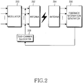
- FIG. 2 illustrates an operation in a Node B for assigning sub-carriers to a User Equipment (UE) in an OFDM mobile communication system.
- UE User Equipment
- Transmission data is modulated in a modulator 200 and transmitted through an antenna 202.
- the modulated data is transmitted on a plurality of sub-carriers.
- the Node B uses all of the sub-carriers or a selected part of the sub-carriers, for transmission of the modulated data.
- a feedback information generator 206 estimates the channel condition of data received through a receive antenna 204.
- the feedback information generator 206 measures the Signal-to-Interference power Ratio (SIR) or Channel-to-Noise Ratio (CNR) of the received signal. That is, the feedback information generator 206 measures the channel condition of an input signal transmitted on a particular channel (or sub-carrier and transmits the measurement to a sub-carrier allocator 208.
- Table 1 illustrates an example of feedback information that the feedback information generator 206 transmits to the sub-carrier allocator 208.
- data is transmitted on N sub-carriers.
- Feedback information a to g is an SIR or CNR generated from the feedback information generator 206.
- the sub-carrier allocator 208 determines a sub-carrier on which data is delivered based on the feedback information.
- the sub-carrier allocator 208 selects a sub-carrier having the highest SIR or CNR. If two or more sub-carriers are used between the Node B and the UE, as many sub-carriers having the highest SIRs or CNRs as required are selected sequentially.
- the sub-carrier allocator 208 assigns sub-carriers in the order of sub-carrier #0, sub-carrier #1, sub-carrier #3, sub-carrier #2, and so on. If one sub-carrier is needed, sub-carrier #0 is selected. If two sub-carriers are used, sub-carrier #0 and sub-carrier #1 are assigned. If three sub-carriers are used, sub-carrier #0, sub-carrier #1, and sub-carrier #3 are assigned. If four sub-carriers are used, sub-carrier #0, sub-carrier #1, sub-carrier #3 and sub-carrier #2 are assigned.
- the above-described sub-carrier assignment is performed in two stages: one is to arrange feedback information according to channel conditions and the other is to assign as many sub-carriers as needed to a UE based on the feedback information.
- the feedback information generator measures the channel condition for each subcarrier and transmits the channel condition measurement to the sub-carrier allocator.
- an existing mobile communication system is limited in the data rate at which uplink data is transmitted. Since the uplink is at a low rate, it is impossible to transmit the measured channel condition information to the Node B on the low-rate uplink.
- the sub-carrier assignment must be periodic and that is shorter than a coherence time.
- WO 02/49306 discloses a method and apparatus for subcarrier selection for systems is described.
- a method for subcarrier for a system employing orthogonal frequency division multiple access comprises partitioning subcarriers into groups of at least one cluster of subcarriers, receiving an indication of a selection by the subscriber of one or more groups in the groups, and allocating at least one cluster in the one or more groups of clusters selected by the subcarrier for use in communication with the subscriber.
- OFDMA orthogonal frequency division multiple access
- An object of the present invention is to substantially solve at least the above problems and/or disadvantages and to provide at least the advantages below. Accordingly, an object of the present invention is to provide an apparatus and method for reducing feedback information transmitted on an uplink.
- Another object of the present invention is to provide an apparatus and method for assigning different sub-carriers to a user equipment (UE) according to a varying channel condition.
- a further object of the present invention is to provide an apparatus and method for prioritizing UEs and assigning sub-carriers to the UEs according to their priority levels when the UEs request sub-carriers.
- an apparatus and method for assigning sub-carriers in an Orthogonal Frequency Division Multiplex (OFDM) system in an OFDM system that transmits data through at least one transmit antenna, assigning at least two sub-carriers in a predetermined frequency band to a UE, for data transmission.
- OFDM Orthogonal Frequency Division Multiplex
- a Node B groups sub-carriers available to the OFDM system into sub-carrier groups, each having at least two sub-carriers, transmits data to the UE on sub-carriers in the sub-carrier groups, selects at least one sub-carrier group for the UE based on channel condition information about each of the sub-carrier groups received from the UE, and assigns the selected sub-carrier group to the UE.
- an OFDM system that transmits data through at least one transmit antenna, assigning to at least two sub-carriers in a predetermined frequency band from a Node B, for data transmission.
- a UE receives from the Node B information about sub-carrier groups.
- the sub-carrier groups are produced by grouping sub-carriers available to the OFDM system, each having at least two sub-carriers.
- the UE then generates channel condition information about data received on sub-carriers of the sub-carrier groups and produces channel condition information about each of the sub-carrier groups.
- the UE transmits the channel condition information about the sub-carrier groups to the Node B.
- an OFDM system that transmits data through at least one transmit antenna, assigning at least two sub-carriers in a predetermined frequency band from a Node B to a UE.
- the Node B groups sub-carriers available to the OFDM system into sub-carrier groups, each having at least two sub-carriers, transmits data to the UE on sub-carriers in the sub-carrier groups, selects a sub-carrier group for the UE based on channel condition information about each of the sub-carrier groups received from the UE, and assigns the selected sub-carrier group to the UE.
- the UE generates channel condition information about data received on the sub-carriers of the sub-carrier groups, produces channel condition information about each of the sub-carrier groups, and transmits the channel condition information about the sub-carrier groups to the Node B.
- FIG. 3 is a block diagram illustrating an operation in a Node B for assigning sub-carriers to a user equipment (UE) in a single-antenna Orthogonal Frequency Division Multiplex (OFDM) system according to an embodiment of the present invention.
- One or more sub-carrier groups are set, each having a plurality of sub-carriers.
- the UE transmits feedback information on a per-sub-carrier group basis, not on a per-sub-carrier basis.
- the sub-carrier assignment to the UE in the Node B will be described with reference to FIG. 3 .
- N sub-carriers are available and grouped into G sub-carrier groups in an OFDM mobile communication system. Grouping of the sub-carriers will first be described.
- the number of sub-carrier groups may vary according to channel conditions. In the case of a channel experiencing serious frequency selective fading, the number of sub-carriers in one group is reduced, whereas in the case of a frequency flat fading channel, one group has more sub-carriers. Also, the data rate of the low-rate uplink may be considered. Therefore, G is determined according to the number of sub-carriers in each group.
- Sub-carriers can be selected for a sub-carrier group by Alternative Sub-carrier Allocation(ASA) or Sub-band Sub-carrier Allocation (SSA).
- ASA Sub-carrier Allocation
- SSA Sub-band Sub-carrier Allocation
- the ASA even numbered subcarriers (sub-carrier #0, sub-carrier #2, ..., sub-carrier #N-2) are included in a first group, and odd numbered subcarriers (sub-carrier #1, sub-carrier #3, ..., sub-carrier #N-1) are included in a second group.
- the SSA groups sub-carrier #0, sub-carrier #1, ..., sub-carrier #(N/2-1) in a first group, and sub-carrier #N/2, sub-carrier #(N/2+1), ..., sub-carrier #N-1 in a second group. It should be appreciated by those skilled in the art that the present invention is not limited to the ASA or SSA methods.
- the Node B selects sub-carriers for each sub-carrier group according to whether the UE requests packet data communication or circuit data communication and according to a desired quality of service (QoS).
- QoS quality of service
- the following description assumes the grouping of directly successive sub-carriers into one group. It should be obvious, however, that many other methods are applicable to the present invention including grouping sub-carriers spaced by a predetermined interval or longer into one group, or cyclically grouping sub-carriers in to every predetermined time periods, and the like. If the grouping method is changed, the Node B notifies the UE of the change in grouping by physical layer signaling or higher-layer signaling. This signaling is beyond the scope of the present invention and thus its detailed description is not provided here. For example, the physical layer signaling may take place on an existing High Speed-Downlink Packet Access (HS-DPA) channel, or a High Speed-Shared Control Channel (HS-SCCH).
- HS-DPA High Speed-Downlink Packet Access
- HS-SCCH High Speed-Shared Control Channel
- a plurality of groups, a modulator, a plurality of adders, a transmit antenna, a receive antenna, a feedback information generator, and a sub-carrier allocator are provided as illustrated in FIG. 3 .
- a modulator 300 modulates received signals and transmits the modulated signals to a plurality of groups.
- the number of the groups is determined according to the number of sub-carriers used and a coherent bandwidth.
- Each group assigns received modulated signals to sub-carriers. As stated, each group has successive sub-carriers.
- a first group 310 assigns received modulated signals to the sub-carriers of the first group 310 and transmits them to an adder 320.
- a G th group 312 assigns received modulated signals to the sub-carriers of the G th group 312 and transmits them to an adder 322.
- the adder 320 adds the received signals and transmits the sum to a transmit antenna 330, and the adder 322 adds the received signals and transmits the sum to the transmit antenna 330.
- the transmit antenna 330 transmits the signals to a receive antenna 340 on a radio channel.
- the receive antenna 340 transmits the signals received on the sub-carriers to a feedback information generator 350.
- the feedback information generator 350 sorts the signals by groups.
- the feedback information generator 350 measures the channel condition of signals received on sub-carriers in each group and transmits the measurement to a sub-carrier allocator 360. The operation of the feedback information generator 350 will be described later in more detail.
- the sub-carrier allocator 360 selects a sub-carrier group to be assigned to the UE based on the received channel condition information (i.e. feedback information).
- a base station (BS) communicates with the UE using the selected sub-carrier group.
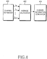
- FIG. 4 is a block diagram of the feedback information generator. With reference to FIG. 4 , the operation of the feedback information generator will now be described.
- the feedback information generator comprises a channel estimator 400, an average calculator 402, and a channel information generator 404.
- the channel estimator 400 channel-estimates a received signal.
- the channel estimation is performed on a sub-carrier basis.
- a Signal to Interference power Ratio SIR
- Signal to Interference plus Noise Ratio SINR
- Bit Error Rate BER
- Frame Error Rate FER
- CNR Channel-to-Noise Ratio
- An exemplary embodiment of the present invention takes the SIR into account. While sub-carriers in one group are used by way of example, the channel estimator 400 can channel-estimate all received sub-carriers.
- the average calculator 402 calculates the average of SIRs (channel estimate values) measured for the sub-carriers of a particular group in the channel estimator 400 and outputs the average SIR as a channel estimate value for the group. Receiving channel estimate values for all received sub-carriers, the average calculator 402 sorts the channel estimate values by groups and calculates the average of channel estimate values for each sub-carrier group.
- SIR g is the average of channel estimate values for the sub-carriers of a sub-carrier group
- SIR f is a channel estimate value for a sub-carrier
- L is the number of sub-carriers in one group
- G is the number of the groups
- f represents a sub-carrier.
- the average calculator 402 Upon receipt of channel estimate values for all received sub-carriers, the average calculator 402 computes the average channel estimate value for each group by Eq. (1).
- the average channel estimate values for the groups are illustrated in Table 2. Table 2 Group number Average channel estimate value 1 st group B 2 nd group A 3 rd group E 4 th group C ... ... G th group G
- the channel information generator 404 maps the average channel estimate values to predetermined values in a preset rule.
- An exemplary set of values to which the average channel estimate values are mapped are illustrated in Table 3.
- the average channel estimate values are mapped to four preset values in Table 3.
- the range of average channel estimate values mapped to the respective mapping values are adjusted by user selection.
- four mapping values are used in Table 3, the average channel estimate values can be mapped to at least two preset values by user selection.
- the average channel estimate values are classified into too many preset values, more bits are used to identify the present values, thereby increasing the volume of data on the uplink. Therefore, the number of mapping values is determined appropriately by taking the uplink into account.
- the ranges of average channel estimate values mapped to "00" and “11" are relatively wide, including A and B, and F and G, respectively, because the probability of the highest and lowest average channel estimate values is low. Since an intermediate average channel estimate value is highly probable, its range mapped to "10" is relatively narrow, thus including only E. Consequently, the probabilities of the mapping values are approximate.
- mapping values can be set by comparing the average channel estimate values with no regard to their absolute generation probabilities. For example, given four groups, "00” is assigned to a group having the highest average estimate value, and "01", "10” and “11” are sequentially assigned to the other groups in a descending order of average estimate values. This mapping method is adopted in an exemplary embodiment of the present invention, though many other methods are available.
- Table 4 illustrates an example of feedback information that the channel information generator 404 delivers to the sub-carrier allocator.
- Table 4 Group number Feedback information 1 st group 00 2 nd group 11 3 rd group 10 4 th group 01 ... ... G th group 11
- the sub-carrier allocator 360 selects a sub-carrier group to assign to the UE based on the feedback information. If the sub-carrier allocator 360 receives the feedback information illustrated in Table 4 and needs one sub-carrier group, it selects the 1 st group (with feedback of "00") and assigns the sub-carriers of the selected sub-carrier group to the UE. If two sub-carriers groups are needed, the sub-carrier allocator 360 assigns the sub-carriers of the first and fourth groups (feedback values of "00" and "01", respectively) to the UE.
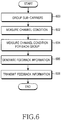
- FIG. 5 is a flowchart illustrating a Node B operation according to an embodiment of the present invention.
- the Node B groups sub-carriers into a plurality of sub-carrier groups according to the number of the sub-carriers and a coherent bandwidth in step 500. It is assumed that each group has successive sub-carriers. For reference, the sub-carriers of each sub-carrier group can be changed every predetermined time period. Otherwise, the same specific band might be repeatedly assigned to a particular user. For example, if a first sub-carrier group includes sub-carriers #0 to #5 at an initial transmission, it may have sub-carriers #2 to #7 a user-determined time later. Upon another time-out, the first group may have sub-carriers #4 to #9. Accordingly, sub-carriers in the other sub-carrier groups are also changed.
- step 502 the Node B assigns transmission data to the sub-carrier groups, that is, to the sub-carriers of each sub-carrier group.
- the Node B transmits the data to the UE in step 504.
- the Node B waits until feedback information is received in step 506.
- the feedback information represents the channel condition of each sub-carrier group.
- the channel condition of each sub-carrier group is the average channel condition values measured for the sub-carriers in the sub-carrier group.
- the Node B selects a sub-carrier group by which to transmit data to the UE.
- the Node B arranges the feedback information in an order of good channel condition and selects the sub-carrier group based on the feedback information.
- the Node B transmits data to the UE on sub-carriers belonging to the selected sub-carrier group in step 510.
- FIG. 6 is a flowchart illustrating a UE operation according to an embodiment of the present invention.
- step 600 the UE groups sub-carriers into a plurality of sub-carrier groups in the same manner as step 500 of FIG. 5 .
- the UE can receive formation about the sub-carrier groups set in the Node B on the same channel as a different channel from the channel on which the data is received.
- the UE measures the channel conditions (i.e. SNRs or CNRs) of received sub-carriers.
- the UE calculates the channel condition of each sub-carrier group using the channel condition measurements in step 604. Specifically, the UE rts the received sub-carriers by groups and calculates the average of the channel condition values of the sub-carriers in each sub-carrier group. This average is the channel condition of the sub-carrier group. Instead of calculating the average of e channel condition values of the sub-carriers in each sub-carrier group, they can summed.
- step 606 the UE generates feedback information from the channel condition formation for each sub-carrier group. If the channel condition information is the m of channel condition values for the sub-carriers in each sub-carrier group, the edback information is generated from channel estimate value sums rather than erage channel estimate values illustrated in Table 3. Assuming the sub-channels e weighted equally, the same result is achieved whether the averages or the ms are used in generating the feedback information in step 608, although in ernate embodiments, weighted calculations may be used.
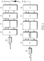
- FIG. 7 is a block diagram of an OFDM mobile communication system using multiple transmit and receive antennas according to anembodiment of the present invention.
- Each transmit antenna transmits data on a plurality of sub-carriers at a predetermined frequency.
- a Node B for a Node B to assign sub-carriers to a UE, a plurality of groups, a modulator, a plurality of adders, transmit antennas, receive antennas, a feedback information generator, and a sub-carrier allocator are provided.
- a modulator 700 modulates received signals and transmits the modulated signals to a plurality of groups.
- the number of the groups is determined according to the number of sub-carriers used, a coherent bandwidth, and the number of transmit/receive antennas.
- Each group assigns received modulated signals to sub-carriers. As stated earlier, each group has successive sub-carriers.
- a first group 710 assigns received modulated signals to the sub-carriers of the first group 710 and transmits them to an adder 720.
- a G th group 712 assigns received modulated signals to the sub-carriers of the G th group 712 and transmits them to an adder 722.
- the adder 720 adds the received signals and transmits the sum to an antenna mapper 730, and the adder 722 adds the received signals and transmits the sum to the antenna mapper 730.
- the antenna mapper 730 assigns the sub-carrier groups to transmit antennas 740, 742 and 744.
- the antenna mapper 730 may assign the sub-carriers of a group to one or more transmit antennas. That is, the sub-carriers of the first group 710 are transmitted on at least one of the transmit antennas 740, 742 and 744. It is assumed hereinbelow that the antenna mapper 730 maps the sub-carriers of a group such that the sub-carriers are delivered to a receiver through the transmit antennas 740, 742 and 744.
- the sub-carrier groups are transmitted to receive antennas 750, 752 and 754 through the transmit antennas 740, 742 and 744. While the same number of transmit and receive antennas are used in FIG. 7 , the number of transmit and receive antennas can be controlled by user selection.
- the receive antennas 750, 752 and 754 deliver received sub-carrier groups to a feedback information generator 760.
- the feedback information generator 760 generates feedback information for the sub-carrier groups in the same manner as the feedback information generator 350 illustrated in FIG. 3 . Yet, the feedback information generator 760 generates more feedback information than the counterpart 350 and that of the respective transmit antennas 740, 742 and 744.
- Table 5 illustrates an example of the feedback information generated in the feedback information generator 760. Table 5 1 st group 2 nd group ... G th group Transmit antenna 740 00 01 ... 11 Transmit antenna 742 01 10 ... 01 ... ... ... ... ... ... Transmit antenna 744 01 10 ... 00
- the feedback information generator 760 generates the feedback information for each group and for transmit antenna as illustrated in Table 5 and transmits the feedback information to a sub-carrier allocator 770.
- the sub-carrier allocator 770 selects a sub-carrier group and a transmit antenna for a particular UE and controls the first to G th groups 710 to 712 and the antenna mapper 730 based on the selection information.
- Table 6 lists feedback information for each transmit antenna and for each UE for sub-carrier assignment in the sub-carrier allocator 770.
- the sub-carrier allocator 770 receiving the feedback information illustrated in Table 5 from two UEs each having two antennas, arranges the feedback information as illustrated in Table 6.
- Table 6 1 st group 2 nd group ... G th group 1 st transmit antenna, UE1 00 01 ... 11 1 st transmit antenna, UE2 01 00 ... 01 2 nd transmit antenna, UE 1 11 11 ... 10 2 nd transmit antenna, UE2 01 10 ... 00
- UE 1 has the best channel condition when data is transmitted on the sub-carriers of the first group through the first transmit antenna
- UE 2 has the best channel condition when data is transmitted on the sub-carriers of the second group through the first transmit antenna, or when data is transmitted on the sub-carriers of the G th group through the second transmit antenna. Therefore, the sub-carrier allocator 770 controls data to be transmitted to UE1 on the sub-carrier of the first group through the first transmit antenna, and to UE2 on the sub-carriers of the G th group through the second transmit antenna.
- a plurality of transmit antennas and a plurality of sub-carrier groups offer a good channel condition to a UE, they are prioritized according to a requested QoS and the type of a requested service. For example, when UE 1 requests packet data and UE 2 requests circuit data and the UEs are at the best channel condition for the same transmit antenna and sub-carrier group, the sub-carrier allocator 770 gives priority to UE 1 requesting packet data over UE 2 requesting circuit data. Yet, sub-carrier assignment criteria are implementation-dependent.
- FIG. 8 illustrates the format of feedback information transmitted from a UE to a Node B in the multi-antenna system according to an embodiment of the present invention. Since the UE and the Node B are aware of the grouping of the sub-carriers, the UE transmits feedback information indexes for the first group to the G th group without any particular indexes for the groups and the Node B assigns a sub-carrier group to the UE based on the received information.
- the feedback information may be transmitted on the HS-DPCCH for HS-DPA, for example.
- the present invention effects single or multi-antenna select diversity in OFDM. Also, transmission of uplink feedback information on a per-sub-carrier group basis leads to efficient use of radio resources.
Description
- The present invention relates generally to an Orthogonal Frequency Division Multiplex OFDM mobile communication system. In particular, the present invention relates to a method and apparatus in a Node B for assigning sub-carriers to a mobile terminal for data transmission/reception.
- A signal transmitted on a radio channel arrives at a receiver from different paths because of obstacles between a transmitter and the receiver. The characteristics of the multi-path radio channel are defined by the maximum delay spread and signal transmission period of the channel. If the transmission period is longer than the maximum delay spread, no interference is generated between successive signals and the channel is characterized by frequency non-selective fading in a frequency domain. For high-speed transmission in a wide band, however, the transmission period is shorter than the maximum delay spread, causing interference between successive signals. Thus, a received signal undergoes inter-symbol interference (ISI). In this case, the channel is characterized by frequency selective fading in the frequency domain. A single-carrier transmission scheme adopting coherent modulation requires an equalizer to eliminate the ISI. Also, as the data rate increases, distortion caused by the ISI becomes severe, thereby increasing the complexity of the equalizer. As a solution to the equalizer problem in the single-carrier transmission scheme, Orthogonal Frequency Division Multiplex (OFDM) was proposed.
- Typically, OFDM is defined as a two-dimensional access technology comprising Time Division Access (TDA) and Frequency Division Access (FDA). Therefore, each OFDM symbol is transmitted on a predetermined sub-channel composed of distributed sub-carriers.
- The orthogonal nature of OFDM allows the spectrums of sub-channels to overlap, having a positive effect on spectral efficiency. Since OFDM modulation/demodulation is implemented by Inverse Fast Fourier Transform (IFFT)/Fast Fourier Transform (FFT), a modulator/demodulator can be efficiently realized digitally. Also, the robustness of OFDM against frequency selective fading and narrow band interference makes OFDM effective for high-speed data transmission standards such as IEEE 802.11a, IEEE 802.16a, and IEEE 802.16b for a large-volume radio communication system.
- OFDM is a special case of Multi Carrier Modulation (MCM) in which a serial symbol sequence is converted to parallel symbol sequences and modulated to mutually orthogonal sub-carriers (sub-channels) prior to transmission.
- The first MCM systems appeared in the late 1950's for military high frequency radio communication, and OFDM with overlapping orthogonal sub-carriers was initially developed in the 1970's. In view of orthogonal modulation between multiple carriers, OFDM has limitations in actual implementation for systems. In 1971, Weinstein, et. al. proposed an OFDM scheme that applies Discrete Fourier Transform (DFT) to parallel data transmission as an efficient modulation/demodulation process, which was a driving force for the development of OFDM. Also, the introduction of a guard interval and a cyclic prefix as the guard interval further mitigates adverse effects of multi-path propagation and delay spread on systems. This is a reason why OFDM has been widely exploited for digital data communications such as digital audio broadcasting (DAB), digital TV broadcasting, wireless local area network (WLAN), and wireless asynchronous transfer mode (W-ATM).
- Although hardware complexity was an obstacle to widespread use of OFDM, recent advances in digital signal processing technology including FFT and IFFT enable OFDM to be implemented. OFDM, similar to Frequency Division Multiplexing (FDM), provides optimum transmission efficiency in high-speed data transmission because it transmits data on sub-carriers, maintaining orthogonality among them. The optimum transmission efficiency is further attributed to good frequency use efficiency and robustness against multi-path fading in OFDM. Overlapping frequency spectrums lead to efficient frequency use and robustness against frequency selective fading and multi-path fading. OFDM reduces the effects of the ISI by using guard intervals and enables the provisioning of a simple equalizer hardware structure. Furthermore, since OFDM is robust against impulse noise, it is increasingly popular in communication systems.
-
FIG. 1 is a block diagram of a conventional OFDM mobile communication system. Its structure will be described in detail with reference toFIG. 1 . - For the input of bits, a
channel encoder 100 outputs code symbols. A serial-to-parallel (S/P)converter 105 converts a serial code symbol sequence received from thechannel encoder 100 to parallel symbol sequences. Amodulator 110 maps the code symbol to a signal constellation by Quadrature Phase Shift Keying (QPSK), 8-ary Phase Shift Keying (8PSK), 16-ary Quadrature Amplitude Modulation (16QAM), or 64-ary Quadrature Amplitude Modulation (64QAM). The number of bits forming a modulation symbol is preset for each of the modulations: a QPSK modulation symbol has 2 bits, a 8PSK modulation symbol has 3 bits, a 16QAM modulation symbol has 4 bits, and a 64QAM modulation symbol has 6 bits. An IFFT 115 inverse-fast-Fourier-transforms modulation symbols received from themodulator 110. A parallel-to-serial (P/S)converter 120 converts parallel symbols received from the IFFT 115 to a serial symbol sequence. The serial symbols are transmitted through atransmit antenna 125. - A
receive antenna 130 receives the symbols from thetransmit antenna 125. A serial-to-parallel (S/P)converter 135 converts a received serial symbol sequence to parallel symbols. An FFT 140 fast-Fourier-transforms the parallel symbols. Ademodulator 145, having the same signal constellation as used in themodulator 110, demodulates the FFT symbols to binary symbols by the signal constellation. The demodulation depends on the modulation. Achannel estimator 150 channel-estimates the demodulated binary symbols. The channel estimation estimates situations involved in transmission of data from the transmit antenna, to thereby enable efficient data transmission. A P/S converter 155 converts the channel-estimated binary symbols to a serial symbol sequence. Adecoder 160 decodes the serial binary symbols and outputs decoded binary bits. -
FIG. 2 illustrates an operation in a Node B for assigning sub-carriers to a User Equipment (UE) in an OFDM mobile communication system. With reference toFIG. 2 , sub-carrier assignment to a UE from a Node B will be described below. - Transmission data is modulated in a
modulator 200 and transmitted through anantenna 202. As stated, the modulated data is transmitted on a plurality of sub-carriers. The Node B uses all of the sub-carriers or a selected part of the sub-carriers, for transmission of the modulated data. - A
feedback information generator 206 estimates the channel condition of data received through a receiveantenna 204. Thefeedback information generator 206 measures the Signal-to-Interference power Ratio (SIR) or Channel-to-Noise Ratio (CNR) of the received signal. That is, thefeedback information generator 206 measures the channel condition of an input signal transmitted on a particular channel (or sub-carrier and transmits the measurement to asub-carrier allocator 208. Table 1 illustrates an example of feedback information that thefeedback information generator 206 transmits to thesub-carrier allocator 208.Table 1 Sub-carrier Feedback information Sub-carrier #0 a Sub-carrier #1 b Sub-carrier #2 d Sub-carrier #3 c Sub-carrier #4 e Sub-carrier #5 g Sub-carrier #6 d Sub-carrier #7 e ... ... Sub-carrier #N-1 f - In the case illustrated in Table 1, data is transmitted on N sub-carriers. Feedback information a to g is an SIR or CNR generated from the
feedback information generator 206. Thesub-carrier allocator 208 determines a sub-carrier on which data is delivered based on the feedback information. Thesub-carrier allocator 208 selects a sub-carrier having the highest SIR or CNR. If two or more sub-carriers are used between the Node B and the UE, as many sub-carriers having the highest SIRs or CNRs as required are selected sequentially. If the SIR or CNR is higher in the order of a>b>c>d>e>f>g, thesub-carrier allocator 208 assigns sub-carriers in the order ofsub-carrier # 0,sub-carrier # 1, sub-carrier #3,sub-carrier # 2, and so on. If one sub-carrier is needed,sub-carrier # 0 is selected. If two sub-carriers are used,sub-carrier # 0 andsub-carrier # 1 are assigned. If three sub-carriers are used,sub-carrier # 0,sub-carrier # 1, and sub-carrier #3 are assigned. If four sub-carriers are used,sub-carrier # 0,sub-carrier # 1, sub-carrier #3 andsub-carrier # 2 are assigned. - The above-described sub-carrier assignment is performed in two stages: one is to arrange feedback information according to channel conditions and the other is to assign as many sub-carriers as needed to a UE based on the feedback information. The feedback information generator measures the channel condition for each subcarrier and transmits the channel condition measurement to the sub-carrier allocator. However, an existing mobile communication system is limited in the data rate at which uplink data is transmitted. Since the uplink is at a low rate, it is impossible to transmit the measured channel condition information to the Node B on the low-rate uplink. Moreover, when the channel environment varies with time as in a mobile communication system, the sub-carrier assignment must be periodic and that is shorter than a coherence time. However, when the feedback information is delivered on a sub-carrier basis as described before, it takes a long time to transmit the feedback information, which makes it impossible to assign subcarries to the UE periodically. The transmission of feedback information for each sub-carrier seriously reduces available radio resources. Therefore, techniques to solve these problems are studied.
WO 02/49306 - An object of the present invention is to substantially solve at least the above problems and/or disadvantages and to provide at least the advantages below. Accordingly, an object of the present invention is to provide an apparatus and method for reducing feedback information transmitted on an uplink.
- Another object of the present invention is to provide an apparatus and method for assigning different sub-carriers to a user equipment (UE) according to a varying channel condition.
A further object of the present invention is to provide an apparatus and method for prioritizing UEs and assigning sub-carriers to the UEs according to their priority levels when the UEs request sub-carriers. - The invention is defined by the appended claims. Embodiments not defined in the appended claims are regarded as examples useful for better understanding the claimed invention.
- The above objects are achieved by providing an apparatus and method for assigning sub-carriers in an Orthogonal Frequency Division Multiplex (OFDM) system. According to one aspect of the present disclosure, in an OFDM system that transmits data through at least one transmit antenna, assigning at least two sub-carriers in a predetermined frequency band to a UE, for data transmission. A Node B groups sub-carriers available to the OFDM system into sub-carrier groups, each having at least two sub-carriers, transmits data to the UE on sub-carriers in the sub-carrier groups, selects at least one sub-carrier group for the UE based on channel condition information about each of the sub-carrier groups received from the UE, and assigns the selected sub-carrier group to the UE.
- According to another aspect of the present disclosure, in an OFDM system that transmits data through at least one transmit antenna, assigning to at least two sub-carriers in a predetermined frequency band from a Node B, for data transmission. A UE receives from the Node B information about sub-carrier groups. The sub-carrier groups are produced by grouping sub-carriers available to the OFDM system, each having at least two sub-carriers. The UE then generates channel condition information about data received on sub-carriers of the sub-carrier groups and produces channel condition information about each of the sub-carrier groups. The UE transmits the channel condition information about the sub-carrier groups to the Node B.
- According to a further aspect of the present disclosure, in an OFDM system that transmits data through at least one transmit antenna, assigning at least two sub-carriers in a predetermined frequency band from a Node B to a UE. The Node B groups sub-carriers available to the OFDM system into sub-carrier groups, each having at least two sub-carriers, transmits data to the UE on sub-carriers in the sub-carrier groups, selects a sub-carrier group for the UE based on channel condition information about each of the sub-carrier groups received from the UE, and assigns the selected sub-carrier group to the UE. The UE generates channel condition information about data received on the sub-carriers of the sub-carrier groups, produces channel condition information about each of the sub-carrier groups, and transmits the channel condition information about the sub-carrier groups to the Node B.
- The above and other objects, features and advantages of the present invention will become more apparent from the following detailed description when taken in conjunction with the accompanying drawings in which:
-
FIG. 1 is a block diagram illustrating a conventional Orthogonal Frequency Division Multiplex (OFDM) mobile communication system; -
FIG. 2 is a block diagram illustrating a conventional operation for assigning sub-carriers to a user equipment (UE) in a sub-carrier allocator of a Node B in the OFDM mobile communication system ofFIG. 1 ; -
FIG. 3 is a block diagram illustrating an operation for assigning sub-carriers to a UE in a sub-carrier allocator of a Node B in a single-carrier OFDM system according to an embodiment of the present invention; -
FIG. 4 is a block diagram illustrating a feedback information generator illustrated inFIG. 3 ; -
FIG. 5 is a flowchart illustrating a Node B operation according to an embodiment of the present disclosure; -
FIG. 6 is a flowchart illustrating a UE operation according to an embodiment of the present disclosure; -
FIG. 7 is a block diagram illustrating an operation for assigning sub-carriers to a UE in the sub-carrier allocator of the Node B in a multi-antenna OFDM system according to an embodiment of the present invention; and -
FIG. 8 is a block diagram illustrating the format of feedback information generated at the UE and transmitted to the Node B in the multi-antenna OFDM system according to an second embodiment of the present disclosure. - It should be understood that in the drawings, like reference numbers refer to like features and structures.
- Embodiments of the present invention will be described with reference to the accompanying drawings. In the following description, well-known functions or constructions are not described in Detail.
FIG. 3 is a block diagram illustrating an operation in a Node B for assigning sub-carriers to a user equipment (UE) in a single-antenna Orthogonal Frequency Division Multiplex (OFDM) system according to an embodiment of the present invention. One or more sub-carrier groups are set, each having a plurality of sub-carriers. The UE transmits feedback information on a per-sub-carrier group basis, not on a per-sub-carrier basis. Hereinafter, the sub-carrier assignment to the UE in the Node B will be described with reference toFIG. 3 .
N sub-carriers are available and grouped into G sub-carrier groups in an OFDM mobile communication system. Grouping of the sub-carriers will first be described. The number of sub-carrier groups may vary according to channel conditions. In the case of a channel experiencing serious frequency selective fading, the number of sub-carriers in one group is reduced, whereas in the case of a frequency flat fading channel, one group has more sub-carriers. Also, the data rate of the low-rate uplink may be considered. Therefore, G is determined according to the number of sub-carriers in each group. - Sub-carriers can be selected for a sub-carrier group by Alternative Sub-carrier Allocation(ASA) or Sub-band Sub-carrier Allocation (SSA). For the purpose of illustration, it is assumed that there are
sub-carriers # 0 to #N-1 and two sub-carrier groups are set. - According to the ASA, even numbered subcarriers (
sub-carrier # 0,sub-carrier # 2, ..., sub-carrier #N-2) are included in a first group, and odd numbered subcarriers (sub-carrier # 1, sub-carrier #3, ..., sub-carrier #N-1) are included in a second group. On the other hand, the SSAgroups sub-carrier # 0,sub-carrier # 1, ..., sub-carrier #(N/2-1) in a first group, and sub-carrier #N/2, sub-carrier #(N/2+1), ..., sub-carrier #N-1 in a second group. It should be appreciated by those skilled in the art that the present invention is not limited to the ASA or SSA methods. Any other suitable method for selection sub-carriers for each sub-carrier group may be used. The Node B selects sub-carriers for each sub-carrier group according to whether the UE requests packet data communication or circuit data communication and according to a desired quality of service (QoS). - Typically, adjacent sub-carriers within the coherence bandwidth of the channel are highly correlated. Therefore, there will not be a significant performance degradation if directly successive sub-carriers are grouped into the same group. Thus, the following description assumes the grouping of directly successive sub-carriers into one group. It should be obvious, however, that many other methods are applicable to the present invention including grouping sub-carriers spaced by a predetermined interval or longer into one group, or cyclically grouping sub-carriers in to every predetermined time periods, and the like. If the grouping method is changed, the Node B notifies the UE of the change in grouping by physical layer signaling or higher-layer signaling. This signaling is beyond the scope of the present invention and thus its detailed description is not provided here. For example, the physical layer signaling may take place on an existing High Speed-Downlink Packet Access (HS-DPA) channel, or a High Speed-Shared Control Channel (HS-SCCH).
- For the Node B to assign sub-carriers to the UE, a plurality of groups, a modulator, a plurality of adders, a transmit antenna, a receive antenna, a feedback information generator, and a sub-carrier allocator are provided as illustrated in
FIG. 3 . - A
modulator 300 modulates received signals and transmits the modulated signals to a plurality of groups. The number of the groups is determined according to the number of sub-carriers used and a coherent bandwidth. Each group assigns received modulated signals to sub-carriers. As stated, each group has successive sub-carriers. Afirst group 310 assigns received modulated signals to the sub-carriers of thefirst group 310 and transmits them to anadder 320. A Gth group 312 assigns received modulated signals to the sub-carriers of the Gth group 312 and transmits them to anadder 322. Theadder 320 adds the received signals and transmits the sum to a transmitantenna 330, and theadder 322 adds the received signals and transmits the sum to the transmitantenna 330. The transmitantenna 330 transmits the signals to a receiveantenna 340 on a radio channel. - The receive
antenna 340 transmits the signals received on the sub-carriers to afeedback information generator 350. Thefeedback information generator 350 sorts the signals by groups. Thefeedback information generator 350 measures the channel condition of signals received on sub-carriers in each group and transmits the measurement to asub-carrier allocator 360. The operation of thefeedback information generator 350 will be described later in more detail. - The
sub-carrier allocator 360 selects a sub-carrier group to be assigned to the UE based on the received channel condition information (i.e. feedback information). A base station (BS) communicates with the UE using the selected sub-carrier group. -
FIG. 4 is a block diagram of the feedback information generator. With reference toFIG. 4 , the operation of the feedback information generator will now be described. The feedback information generator comprises achannel estimator 400, anaverage calculator 402, and achannel information generator 404. - The
channel estimator 400 channel-estimates a received signal. The channel estimation is performed on a sub-carrier basis. As stated before, a Signal to Interference power Ratio (SIR), Signal to Interference plus Noise Ratio (SINR), Bit Error Rate (BER), Frame Error Rate (FER) or Channel-to-Noise Ratio (CNR) is measured as a channel estimate. An exemplary embodiment of the present invention takes the SIR into account. While sub-carriers in one group are used by way of example, thechannel estimator 400 can channel-estimate all received sub-carriers. - The
average calculator 402 calculates the average of SIRs (channel estimate values) measured for the sub-carriers of a particular group in thechannel estimator 400 and outputs the average SIR as a channel estimate value for the group. Receiving channel estimate values for all received sub-carriers, theaverage calculator 402 sorts the channel estimate values by groups and calculates the average of channel estimate values for each sub-carrier group. The operation of theaverage calculator 402 is expressed as
average calculator 402 computes the average channel estimate value for each group by Eq. (1). The average channel estimate values for the groups are illustrated in Table 2.Table 2 Group number Average channel estimate value 1st group B 2nd group A 3rd group E 4th group C ... ... Gth group G - The
channel information generator 404 maps the average channel estimate values to predetermined values in a preset rule. An exemplary set of values to which the average channel estimate values are mapped are illustrated in Table 3.Table 3 Average channel estimate value Mapping value A and B 00 C and D 01 E 10 F and G 11 - The average channel estimate values are mapped to four preset values in Table 3. The range of average channel estimate values mapped to the respective mapping values are adjusted by user selection. Also, although four mapping values are used in Table 3, the average channel estimate values can be mapped to at least two preset values by user selection. However, if the average channel estimate values are classified into too many preset values, more bits are used to identify the present values, thereby increasing the volume of data on the uplink. Therefore, the number of mapping values is determined appropriately by taking the uplink into account.
- In accordance with an embodiment of the present invention, the ranges of average channel estimate values mapped to "00" and "11" are relatively wide, including A and B, and F and G, respectively, because the probability of the highest and lowest average channel estimate values is low. Since an intermediate average channel estimate value is highly probable, its range mapped to "10" is relatively narrow, thus including only E. Consequently, the probabilities of the mapping values are approximate. Alternatively, mapping values can be set by comparing the average channel estimate values with no regard to their absolute generation probabilities. For example, given four groups, "00" is assigned to a group having the highest average estimate value, and "01", "10" and "11" are sequentially assigned to the other groups in a descending order of average estimate values. This mapping method is adopted in an exemplary embodiment of the present invention, though many other methods are available.
- Table 4 illustrates an example of feedback information that the
channel information generator 404 delivers to the sub-carrier allocator.Table 4 Group number Feedback information 1st group 00 2nd group 11 3rd group 10 4th group 01 ... ... Gth group 11 - Hereinafter, it is assumed that feedback information is prioritized in the order of 00, 01, 10 and 11. The
sub-carrier allocator 360 selects a sub-carrier group to assign to the UE based on the feedback information. If thesub-carrier allocator 360 receives the feedback information illustrated in Table 4 and needs one sub-carrier group, it selects the 1st group (with feedback of "00") and assigns the sub-carriers of the selected sub-carrier group to the UE. If two sub-carriers groups are needed, thesub-carrier allocator 360 assigns the sub-carriers of the first and fourth groups (feedback values of "00" and "01", respectively) to the UE. -
FIG. 5 is a flowchart illustrating a Node B operation according to an embodiment of the present invention. - Referring to
FIG. 5 , the Node B groups sub-carriers into a plurality of sub-carrier groups according to the number of the sub-carriers and a coherent bandwidth instep 500. It is assumed that each group has successive sub-carriers. For reference, the sub-carriers of each sub-carrier group can be changed every predetermined time period. Otherwise, the same specific band might be repeatedly assigned to a particular user. For example, if a first sub-carrier group includessub-carriers # 0 to #5 at an initial transmission, it may havesub-carriers # 2 to #7 a user-determined time later. Upon another time-out, the first group may havesub-carriers # 4 to #9. Accordingly, sub-carriers in the other sub-carrier groups are also changed. - In
step 502, the Node B assigns transmission data to the sub-carrier groups, that is, to the sub-carriers of each sub-carrier group. The Node B transmits the data to the UE instep 504. - The Node B waits until feedback information is received in
step 506. The feedback information represents the channel condition of each sub-carrier group. The channel condition of each sub-carrier group is the average channel condition values measured for the sub-carriers in the sub-carrier group. - In
step 508, the Node B selects a sub-carrier group by which to transmit data to the UE. The Node B arranges the feedback information in an order of good channel condition and selects the sub-carrier group based on the feedback information. The Node B transmits data to the UE on sub-carriers belonging to the selected sub-carrier group instep 510. -
FIG. 6 is a flowchart illustrating a UE operation according to an embodiment of the present invention. - Referring to
FIG. 6 , instep 600, the UE groups sub-carriers into a plurality of sub-carrier groups in the same manner asstep 500 ofFIG. 5 . Thus, the UE can receive formation about the sub-carrier groups set in the Node B on the same channel as a different channel from the channel on which the data is received. -
step 602, the UE measures the channel conditions (i.e. SNRs or CNRs) of received sub-carriers. The UE calculates the channel condition of each sub-carrier group using the channel condition measurements instep 604. Specifically, the UE rts the received sub-carriers by groups and calculates the average of the channel condition values of the sub-carriers in each sub-carrier group. This average is the channel condition of the sub-carrier group. Instead of calculating the average of e channel condition values of the sub-carriers in each sub-carrier group, they can summed. -
step 606, the UE generates feedback information from the channel condition formation for each sub-carrier group. If the channel condition information is the m of channel condition values for the sub-carriers in each sub-carrier group, the edback information is generated from channel estimate value sums rather than erage channel estimate values illustrated in Table 3. Assuming the sub-channels e weighted equally, the same result is achieved whether the averages or the ms are used in generating the feedback information instep 608, although in ernate embodiments, weighted calculations may be used. - mobile communication system having one transmit antenna and one receive tenna has been described so far. A description will be made of a mobile communication system having a plurality of transmit antennas and a plurality of receive antennas.
FIG. 7 is a block diagram of an OFDM mobile communication system using multiple transmit and receive antennas according to anembodiment of the present invention. Each transmit antenna transmits data on a plurality of sub-carriers at a predetermined frequency. - Referring to
FIG. 7 , for a Node B to assign sub-carriers to a UE, a plurality of groups, a modulator, a plurality of adders, transmit antennas, receive antennas, a feedback information generator, and a sub-carrier allocator are provided. - A
modulator 700 modulates received signals and transmits the modulated signals to a plurality of groups. The number of the groups is determined according to the number of sub-carriers used, a coherent bandwidth, and the number of transmit/receive antennas. Each group assigns received modulated signals to sub-carriers. As stated earlier, each group has successive sub-carriers. Afirst group 710 assigns received modulated signals to the sub-carriers of thefirst group 710 and transmits them to anadder 720. A Gth group 712 assigns received modulated signals to the sub-carriers of the Gth group 712 and transmits them to anadder 722. Theadder 720 adds the received signals and transmits the sum to anantenna mapper 730, and theadder 722 adds the received signals and transmits the sum to theantenna mapper 730. - The
antenna mapper 730 assigns the sub-carrier groups to transmitantennas antenna mapper 730 may assign the sub-carriers of a group to one or more transmit antennas. That is, the sub-carriers of thefirst group 710 are transmitted on at least one of the transmitantennas antenna mapper 730 maps the sub-carriers of a group such that the sub-carriers are delivered to a receiver through the transmitantennas - The sub-carrier groups are transmitted to receive
antennas antennas FIG. 7 , the number of transmit and receive antennas can be controlled by user selection. - The receive
antennas feedback information generator 760. - The
feedback information generator 760 generates feedback information for the sub-carrier groups in the same manner as thefeedback information generator 350 illustrated inFIG. 3 . Yet, thefeedback information generator 760 generates more feedback information than thecounterpart 350 and that of the respective transmitantennas feedback information generator 760.Table 5 1st group 2nd group ... Gth group Transmit antenna 74000 01 ... 11 Transmit antenna 74201 10 ... 01 ... ... ... ... ... Transmit antenna 744 01 10 ... 00 - The
feedback information generator 760 generates the feedback information for each group and for transmit antenna as illustrated in Table 5 and transmits the feedback information to asub-carrier allocator 770. Thesub-carrier allocator 770 selects a sub-carrier group and a transmit antenna for a particular UE and controls the first to Gth groups 710 to 712 and theantenna mapper 730 based on the selection information. - Table 6 lists feedback information for each transmit antenna and for each UE for sub-carrier assignment in the
sub-carrier allocator 770. For convenience, an OFDM system having two transmit antennas and two UEs is assumed to be used. Thesub-carrier allocator 770, receiving the feedback information illustrated in Table 5 from two UEs each having two antennas, arranges the feedback information as illustrated in Table 6.Table 6 1st group 2nd group ... Gth group 1st transmit antenna, UE1 00 01 ... 11 1st transmit antenna, UE2 01 00 ... 01 2nd transmit antenna, UE 111 11 ... 10 2nd transmit antenna, UE2 01 10 ... 00 - As noted in Table 6,
UE 1 has the best channel condition when data is transmitted on the sub-carriers of the first group through the first transmit antenna, whileUE 2 has the best channel condition when data is transmitted on the sub-carriers of the second group through the first transmit antenna, or when data is transmitted on the sub-carriers of the Gth group through the second transmit antenna. Therefore, thesub-carrier allocator 770 controls data to be transmitted to UE1 on the sub-carrier of the first group through the first transmit antenna, and to UE2 on the sub-carriers of the Gth group through the second transmit antenna. - If a plurality of transmit antennas and a plurality of sub-carrier groups offer a good channel condition to a UE, they are prioritized according to a requested QoS and the type of a requested service. For example, when
UE 1 requests packet data andUE 2 requests circuit data and the UEs are at the best channel condition for the same transmit antenna and sub-carrier group, thesub-carrier allocator 770 gives priority toUE 1 requesting packet data overUE 2 requesting circuit data. Yet, sub-carrier assignment criteria are implementation-dependent. -
FIG. 8 illustrates the format of feedback information transmitted from a UE to a Node B in the multi-antenna system according to an embodiment of the present invention. Since the UE and the Node B are aware of the grouping of the sub-carriers, the UE transmits feedback information indexes for the first group to the Gth group without any particular indexes for the groups and the Node B assigns a sub-carrier group to the UE based on the received information. The feedback information may be transmitted on the HS-DPCCH for HS-DPA, for example. - As described, the present invention effects single or multi-antenna select diversity in OFDM. Also, transmission of uplink feedback information on a per-sub-carrier group basis leads to efficient use of radio resources.
- While the invention has been shown and described with reference to a certain embodiment thereof, it will be understood by those skilled in the art that various changes in form and details may be made therein if they do not depart from the scope of the invention as defined by the appended claims.
Claims (13)
- A method for use in a Node B for assigning at least two sub-carriers in a predetermined frequency band for transmitting data to an user equipment UE for use in an orthogonal frequency division multiplex OFDM system, the method comprising the steps of:transmitting data to the UE on sub-carriers of a plurality of sub-carrier groups from a plurality of transmit antennas, wherein each sub-carrier group comprises at least two adjacent subcarriers;receiving channel condition information about each of the plurality of sub-carrier groups for each transmit antenna of the Node B from the UE;selecting a sub-carrier group for the UE, which is to be used for transmission of the data, and selecting a transmit antenna for transmission of the data, in a descending order of the channel condition information; andtransmitting data on the selected sub-carrier group, through the selected transmit antenna,wherein the channel condition information comprises values representing channel conditions for each sub-carrier group and each transmit antenna.
- The method of claim 1, wherein the sub-carriers of the sub-carrier groups are changed every predetermined time period.
- The method of claim 1, wherein the channel condition information about each of the sub-carrier groups comprises an average of the signal-to-noise ratios SNRs of sub-carriers included in the sub-carrier group.
- The method of claim 1, wherein the selecting step further comprises the step of:
assigning the sub-carrier group to the UE according to a quality of service and a type of a service requested by the UE if the Node B receives channel condition information about the sub-carrier groups from at least two UEs. - A method for use in an user equipment, UE, for assigning at least two sub-carriers in a predetermined frequency band for receiving data from a Node B for use in an orthogonal frequency division multiplex OFDM system, the method comprising the steps of:receiving data transmitted by the Node B on sub-carriers of a plurality of sub-carrier groups from a plurality of transmit antennas, wherein each subcarrier group comprises at least two adjacent subcarriers;generating (606) channel condition information about each of the plurality of sub-carrier groups used for transmission of data for each of the plurality of transmit antennas of the Node B;transmitting (608) the channel condition information to the Node B; andreceiving data transmitted by the Node B on a sub-carrier group through a transmit antenna,wherein the sub-carrier group and the transmit antenna are determined for transmission of the data in a descending order of the channel condition information;wherein the channel condition information comprises values representing channel conditions for each sub-carrier group and each transmit antenna.
- The method of claim 5, wherein signal-to-noise ratio SNR of sub-carriers of the sub-carrier groups is computed by using the received data on subcarriers of the sub-carrier groups.
- The method of claim 6, wherein the channel condition information about each of the sub-carrier groups comprises an average of the SNRs of subcarriers included in the sub-carrier group.
- The method of claim 6, wherein the channel condition information about each of the sub-carrier groups comprises a sum of the SNRs of sub-carriers included in the sub-carrier group.
- The method of claim 5, wherein the sub-carriers of the sub-carrier groups are changed every predetermined time period.
- An apparatus for a Node B for assigning at least two sub-carriers in a predetermined frequency band for transmitting data to an user equipment UE for use in an orthogonal frequency division multiplex OFDM system, the apparatus comprising:a plurality of transmit antennas (740,742,743,744) for transmitting data to the UE on subcarriers of a plurality of subcarrier groups, wherein each subcarrier group comprises at least two adjacent subcarriers;a modulator (700) for modulating data;a controller (770) for receiving channel condition information about each of the plurality of sub-carrier groups for each of the plurality of the transmit antennas of the Node B from the UE, and for selecting a sub-carrier group for the UE, which is to be used for the transmission of the data, and selecting a transmit antenna for transmission of the data, in a descending order of a condition of the channel condition information; anda signal processor for mapping the data to the selected sub-carrier groups under control of the controller,a transmitter (730) for assigning data mapped to the selected sub-carrier group to the selected transmit antenna under control of the controller and transmitting the data on the selected sub-carrier group to the UE through the selected transmit antenna,wherein the channel condition information comprises values representing channel conditions for each sub-carrier group and each transmit antenna.
- The apparatus of claim 10, wherein the Node B changes the sub-carriers of the sub-carrier groups every predetermined time period.
- The apparatus of claim 10, wherein if the Node B receives the channel condition information about the sub-carrier groups from at least two UEs,
the Node B assigns the sub-carrier group to the UE according to a quality of service and a type of service requested by the UE. - An apparatus for a user equipment for receiving data from a Node B for use in an orthogonal frequency division multiplex OFDM system, the apparatus comprising:a demodulator for receiving data transmitted by the Node B on sub-carriers of a plurality of subcarrier groups from a plurality of transmit antennas (740; 742, 744), wherein each subcarrier group comprises at least two adjacent subcarriers;a feedback information generator (760) for generating channel condition information about each of the plurality of sub-carrier groups used for transmission of data for each the plurality of the transmit antennas of the Node B; anda transmitter for transmitting the channel condition information to the Node B,wherein the demodulator further receives data transmitted by the Node B on a sub-carrier group through a transmit antenna, and the sub-carrier group and the transmit antenna are determined for transmission of the data in a descending order of the channel condition information, andwherein the channel condition information comprises values representing channel conditions for each sub-carrier group and each transmit antenna.
Applications Claiming Priority (2)
| Application Number | Priority Date | Filing Date | Title |
|---|---|---|---|
| KR2003058426 | 2003-08-22 | ||
| KR10-2003-0058426A KR100539925B1 (en) | 2003-08-22 | 2003-08-22 | Apparatus and method for sub-carrier alocation in ofdm system |
Publications (2)
| Publication Number | Publication Date |
|---|---|
| EP1509016A1 EP1509016A1 (en) | 2005-02-23 |
| EP1509016B1 true EP1509016B1 (en) | 2018-11-14 |
Family
ID=34056946
Family Applications (1)
| Application Number | Title | Priority Date | Filing Date |
|---|---|---|---|
| EP04018458.2A Expired - Fee Related EP1509016B1 (en) | 2003-08-22 | 2004-08-04 | Apparatus and method for assigning groups of subcarriers in an OFDM system |
Country Status (5)
| Country | Link |
|---|---|
| US (1) | US7545732B2 (en) |
| EP (1) | EP1509016B1 (en) |
| JP (1) | JP4046712B2 (en) |
| KR (1) | KR100539925B1 (en) |
| CN (1) | CN1585394B (en) |
Families Citing this family (87)
| Publication number | Priority date | Publication date | Assignee | Title |
|---|---|---|---|---|
| US8670390B2 (en) | 2000-11-22 | 2014-03-11 | Genghiscomm Holdings, LLC | Cooperative beam-forming in wireless networks |
| US10931338B2 (en) | 2001-04-26 | 2021-02-23 | Genghiscomm Holdings, LLC | Coordinated multipoint systems |
| US9819449B2 (en) | 2002-05-14 | 2017-11-14 | Genghiscomm Holdings, LLC | Cooperative subspace demultiplexing in content delivery networks |
| US10355720B2 (en) | 2001-04-26 | 2019-07-16 | Genghiscomm Holdings, LLC | Distributed software-defined radio |
| US10142082B1 (en) | 2002-05-14 | 2018-11-27 | Genghiscomm Holdings, LLC | Pre-coding in OFDM |
| US10200227B2 (en) | 2002-05-14 | 2019-02-05 | Genghiscomm Holdings, LLC | Pre-coding in multi-user MIMO |
| US9628231B2 (en) | 2002-05-14 | 2017-04-18 | Genghiscomm Holdings, LLC | Spreading and precoding in OFDM |
| US10644916B1 (en) | 2002-05-14 | 2020-05-05 | Genghiscomm Holdings, LLC | Spreading and precoding in OFDM |
| KR100566274B1 (en) * | 2003-11-20 | 2006-03-30 | 삼성전자주식회사 | Apparatus and method for sub-carrier allocation in ofdm system |
| WO2006000955A1 (en) * | 2004-06-24 | 2006-01-05 | Philips Intellectual Property & Standards Gmbh | A method for signaling thestatus of a subcarrier in a mc network and a method for adaptively allocating the subcarriers in a mc network |
| US11381285B1 (en) | 2004-08-02 | 2022-07-05 | Genghiscomm Holdings, LLC | Transmit pre-coding |
| US11552737B1 (en) | 2004-08-02 | 2023-01-10 | Genghiscomm Holdings, LLC | Cooperative MIMO |
| US11184037B1 (en) | 2004-08-02 | 2021-11-23 | Genghiscomm Holdings, LLC | Demodulating and decoding carrier interferometry signals |
| DE05815502T1 (en) * | 2004-10-20 | 2008-05-21 | Qualcomm, Inc., San Diego | MULTI FREQUENCY BAND OPERATION IN WIRELESS NETWORKS |
| KR100764789B1 (en) | 2004-11-16 | 2007-10-11 | 엘지전자 주식회사 | Signal transmission apparatus and method for ofdm system |
| US7590045B2 (en) | 2005-01-11 | 2009-09-15 | Samsung Electronics Co., Ltd | Apparatus and method for transmitting fast feedback information in a wireless communication system |
| US8135088B2 (en) * | 2005-03-07 | 2012-03-13 | Q1UALCOMM Incorporated | Pilot transmission and channel estimation for a communication system utilizing frequency division multiplexing |
| RU2408987C2 (en) * | 2005-04-01 | 2011-01-10 | Нтт Досомо, Инк. | Transmitting device and method of signal transmission |
| EP1722583A1 (en) * | 2005-05-11 | 2006-11-15 | Siemens Aktiengesellschaft | Beam-hopping in a radio communication system |
| KR100768511B1 (en) | 2005-07-19 | 2007-10-18 | 한국전자통신연구원 | Base station transmitter of system for mc-cdma, transmit diversity method for that system, base station transmitter of system for scattered mc-cdma, transmit diversity method for thar system |
| US8229448B2 (en) | 2005-08-01 | 2012-07-24 | Samsung Electronics Co., Ltd. | Apparatus and method for adaptive channel quality feedback in a multicarrier wireless network |
| CN101223718B (en) * | 2005-08-02 | 2011-09-28 | 三菱电机株式会社 | Communication device and radio communication system |
| US8077690B2 (en) * | 2005-08-24 | 2011-12-13 | Motorola Mobility, Inc. | Resource allocation in cellular communication systems |
| WO2007023151A1 (en) * | 2005-08-24 | 2007-03-01 | Nokia Siemens Networks Gmbh & Co. Kg | Method for configuring a radio interface of a radio communication system |
| JP4664980B2 (en) | 2005-08-25 | 2011-04-06 | 富士通株式会社 | Mobile terminal and base station apparatus |
| CN1953437B (en) * | 2005-10-17 | 2010-09-29 | 北京三星通信技术研究有限公司 | Extensional OFDM system and method based on constant subcarrier width |
| US8054894B2 (en) * | 2005-10-31 | 2011-11-08 | Motorola Mobility, Inc. | Method and apparatus for providing channel quality feedback in an orthogonal frequency division multiplexing communication system |
| CN1777161B (en) * | 2005-12-02 | 2010-04-28 | 山东大学 | Adaptive frequency-selecting block transmission method in mobile broadband channel |
| KR100788890B1 (en) | 2005-12-07 | 2007-12-27 | 한국전자통신연구원 | Transmitting Apparatus for transmitting in the multicarrier system using multiple antennas and Receiving Apparatus in the same system |
| KR100819033B1 (en) * | 2005-12-07 | 2008-04-02 | 한국전자통신연구원 | Apparatus & Method for a Statistical Sub-Carrier Mulplexing and Sub-Carrier Multiple Access Optical Network |
| US8412249B2 (en) * | 2005-12-20 | 2013-04-02 | Alcatel Lucent | Resource allocation based on interference mitigation in a wireless communication system |
| JP4870093B2 (en) * | 2005-12-20 | 2012-02-08 | シャープ株式会社 | Communication system and base station and terminal used therefor |
| JP5311711B2 (en) * | 2005-12-22 | 2013-10-09 | 京セラ株式会社 | Communication control system, radio communication terminal and communication control method |
| KR100991796B1 (en) * | 2006-01-13 | 2010-11-03 | 엘지전자 주식회사 | A method and apparatus for achieving transmit diversity and spatial multiplexing using antenna selection based on feedback information |
| WO2007108077A1 (en) * | 2006-03-17 | 2007-09-27 | Fujitsu Limited | Base station device, mobile station device and sub-carrier allocating method |
| GB2436416A (en) | 2006-03-20 | 2007-09-26 | Nec Corp | Signal resource allocation in a communication system using a plurality of subcarriers |
| DK2015595T3 (en) | 2006-04-28 | 2016-02-01 | Panasonic Ip Corp America | RADIO COMMUNICATION BASIC DEVICE DEVICE AND RADIO COMMUNICATION PROCEDURE FOR MULTIBAR COMMUNICATION |
| US8189621B2 (en) | 2006-05-12 | 2012-05-29 | Microsoft Corporation | Stack signaling to application with lack of requested bandwidth |
| US20090203405A1 (en) * | 2006-07-11 | 2009-08-13 | Nokia Corporation | Data transmission method, base station and user transceiver |
| KR100957311B1 (en) * | 2006-08-11 | 2010-05-13 | 삼성전자주식회사 | Uplink Scheduling Method and Apparatus for Mobile Communication System |
| US7483700B2 (en) * | 2006-08-14 | 2009-01-27 | Motorola, Inc. | Method and apparatus for determining appropriate channels for communication |
| KR101251706B1 (en) | 2006-08-21 | 2013-04-05 | 인터디지탈 테크날러지 코포레이션 | Method and apparatus for transmitting scheduling information in a wireless communication system |
| KR100878768B1 (en) * | 2006-09-15 | 2009-01-14 | 삼성전자주식회사 | Method and apparatus for MIMO-OFDM transmitting/receiving |
| EP2066136A4 (en) * | 2006-09-20 | 2013-09-04 | Sharp Kk | Radio communication device, radio communication system, and radio communication method |
| TWI479933B (en) | 2006-10-10 | 2015-04-01 | Interdigital Tech Corp | Method and apparatus for sending feedback for a downlink shared service transmitted to a plurality of wireless transmit/receive units |
| US7860500B2 (en) * | 2006-10-27 | 2010-12-28 | Motorola, Inc. | Method and apparatus for determining appropriate channels for communication |
| JP4898400B2 (en) * | 2006-11-24 | 2012-03-14 | シャープ株式会社 | Wireless transmission device, wireless reception device, wireless communication system, and wireless communication method |
| US8144793B2 (en) | 2006-12-12 | 2012-03-27 | Microsoft Corporation | Cognitive multi-user OFDMA |
| KR101341466B1 (en) * | 2006-12-18 | 2013-12-16 | 엘지전자 주식회사 | adaptive resource allocation method in communication system and transceiver implementing the same |
| AU2008227120B2 (en) | 2007-03-15 | 2011-09-01 | Interdigital Technology Corporation | Method and apparatus for feedback overhead reduction in wireless communications |
| KR100985395B1 (en) | 2007-04-03 | 2010-10-05 | 연세대학교 산학협력단 | APPARATUS AND METHOD FOR TRaNSMISSION IN OFDM COMMUNICATION SYSTEM |
| US7990920B2 (en) * | 2007-04-26 | 2011-08-02 | Samsung Electronics Co., Ltd. | Transmit diversity for acknowledgement and category 0 bits in a wireless communication system |
| US7970085B2 (en) | 2007-05-08 | 2011-06-28 | Microsoft Corporation | OFDM transmission and reception for non-OFDMA signals |
| CA2695500A1 (en) * | 2007-08-07 | 2009-02-12 | Sharp Kabushiki Kaisha | Communication device and reception quality information generation method |
| EP2026488A1 (en) * | 2007-08-14 | 2009-02-18 | Panasonic Corporation | Contiguous CQI report |
| EP2207288A1 (en) * | 2007-10-25 | 2010-07-14 | Sharp Kabushiki Kaisha | Communication device, multicarrier communication system, and communication method |
| ES2354734T3 (en) * | 2007-12-19 | 2011-03-17 | Sony Corporation | OPTIMAL ADJUSTMENT OF THE BIT ERROR RATE (BER) FOR MULTIPORTING ADAPTIVE MODULATION. |
| US8374130B2 (en) | 2008-01-25 | 2013-02-12 | Microsoft Corporation | Orthogonal frequency division multiple access with carrier sense |
| CN101252384B (en) * | 2008-03-28 | 2012-02-22 | 清华大学 | Star loading exchanging method based on OFDM and cross layer design |
| CN101582740A (en) * | 2008-06-27 | 2009-11-18 | 北京新岸线移动多媒体技术有限公司 | Transmitting device, transmitting method and transmitting system for digital broadcast signal |
| CN101582739A (en) * | 2008-06-27 | 2009-11-18 | 北京新岸线移动多媒体技术有限公司 | Transmitting device, transmitting method and transmitting system for digital broadcast signal |
| WO2010025360A2 (en) | 2008-08-29 | 2010-03-04 | Interdigital Patent Holdings, Inc. | Method and apparatus for sending feedback for a downlink shared service and estimating a number of wireless transmit/receive units |
| KR101328790B1 (en) | 2008-10-20 | 2013-11-13 | 인터디지탈 패튼 홀딩스, 인크 | Carrier aggregation |
| CN101488829B (en) * | 2009-01-24 | 2011-12-28 | 华为技术有限公司 | Service processing method, base station and terminal combining adaptive code |
| KR101032224B1 (en) * | 2009-03-06 | 2011-05-02 | 삼성전기주식회사 | Apparatus and method for generating a channel state information for ofdm system |
| JP5548774B2 (en) * | 2009-08-25 | 2014-07-16 | インターデイジタル パテント ホールディングス インコーポレイテッド | Method and apparatus for managing group communications |
| CN103036660B (en) | 2010-04-30 | 2015-09-16 | 北京三星通信技术研究有限公司 | A kind of method of feedback data acceptance state |
| CN101848063B (en) * | 2010-05-21 | 2016-06-08 | 北京新岸线移动多媒体技术有限公司 | Support data transmission method and the wireless local area network (WLAN) system of sub-channel modulation coding |
| JP5489891B2 (en) * | 2010-07-07 | 2014-05-14 | 株式会社Nttドコモ | Base station and method in mobile communication system |
| KR101533793B1 (en) * | 2010-09-28 | 2015-07-09 | 한국전자통신연구원 | Method and apparatus of antenna selection in multi antenna system |
| GB2493702B (en) * | 2011-08-11 | 2016-05-04 | Sca Ipla Holdings Inc | OFDM subcarrier allocations in wireless telecommunications systems |
| CN103688582B (en) * | 2012-07-19 | 2017-06-20 | 华为技术有限公司 | Adaptive frequency domain resource allocation method, device and communication system |
| US9936502B2 (en) | 2013-12-18 | 2018-04-03 | Huawei Technologies Co., Ltd. | System and method for OFDMA resource management in WLAN |
| US9755795B2 (en) | 2013-12-18 | 2017-09-05 | Huawei Technologies Co., Ltd. | System and method for WLAN OFDMA design of subcarrier groups and frame format |
| DE102015205478A1 (en) * | 2015-03-26 | 2016-09-29 | Bayerische Motoren Werke Aktiengesellschaft | Method and device for configuring a transmission connection |
| JP6440075B2 (en) * | 2015-06-22 | 2018-12-19 | 日本電信電話株式会社 | Wireless communication method and wireless communication apparatus |
| US9954917B2 (en) * | 2015-07-23 | 2018-04-24 | Samsung Electronics Co., Ltd. | Transmitting apparatus, receiving apparatus, and control methods thereof |
| CN106685495A (en) * | 2015-11-05 | 2017-05-17 | 索尼公司 | Wireless communication method and wireless communication equipment |
| US9847802B1 (en) * | 2016-08-16 | 2017-12-19 | Xilinx, Inc. | Reconfiguration of single-band transmit and receive paths to multi-band transmit and receive paths in an integrated circuit |
| US10637705B1 (en) | 2017-05-25 | 2020-04-28 | Genghiscomm Holdings, LLC | Peak-to-average-power reduction for OFDM multiple access |
| US10243773B1 (en) | 2017-06-30 | 2019-03-26 | Genghiscomm Holdings, LLC | Efficient peak-to-average-power reduction for OFDM and MIMO-OFDM |
| CN108627818B (en) * | 2018-03-19 | 2023-11-17 | 桂林电子科技大学 | OFDM-based frequency control array radar communication integrated waveform design method |
| EP3915236A4 (en) | 2019-01-25 | 2023-05-24 | Genghiscomm Holdings, LLC | Orthogonal multiple access and non-orthogonal multiple access |
| US11343823B2 (en) | 2020-08-16 | 2022-05-24 | Tybalt, Llc | Orthogonal multiple access and non-orthogonal multiple access |
| WO2020242898A1 (en) | 2019-05-26 | 2020-12-03 | Genghiscomm Holdings, LLC | Non-orthogonal multiple access |
| CN111884980B (en) * | 2020-08-03 | 2021-07-27 | 兰州理工大学 | Generalized index modulation optical OFDM modulation method for wireless optical communication |
| US20220321383A1 (en) * | 2021-04-01 | 2022-10-06 | Telefonaktiebolaget Lm Ericsson (Publ) | Channel estimation for wireless communication network |
Family Cites Families (20)
| Publication number | Priority date | Publication date | Assignee | Title |
|---|---|---|---|---|
| US5726978A (en) * | 1995-06-22 | 1998-03-10 | Telefonaktiebolaget L M Ericsson Publ. | Adaptive channel allocation in a frequency division multiplexed system |
| JP3670445B2 (en) | 1997-06-30 | 2005-07-13 | 株式会社東芝 | Wireless communication system |
| US6131016A (en) * | 1997-08-27 | 2000-10-10 | At&T Corp | Method and apparatus for enhancing communication reception at a wireless communication terminal |
| JP2962299B2 (en) | 1998-01-09 | 1999-10-12 | 日本電信電話株式会社 | Multi-carrier signal transmission device |
| JP2000114846A (en) | 1998-10-06 | 2000-04-21 | Toshiba Corp | System and method for selecting directional antenna, directional antenna base station, and radio terminal |
| JP2000209145A (en) | 1999-01-20 | 2000-07-28 | Nippon Telegr & Teleph Corp <Ntt> | Multi-carrier signal transmitter-receiver |
| JP3826653B2 (en) | 2000-02-25 | 2006-09-27 | Kddi株式会社 | Subcarrier allocation method for wireless communication system |
| JP2001358692A (en) * | 2000-06-14 | 2001-12-26 | Nec Corp | Orthogonal frequency-division multiplex modulating and demodulating circuit |
| US7072315B1 (en) | 2000-10-10 | 2006-07-04 | Adaptix, Inc. | Medium access control for orthogonal frequency-division multiple-access (OFDMA) cellular networks |
| US6947748B2 (en) * | 2000-12-15 | 2005-09-20 | Adaptix, Inc. | OFDMA with adaptive subcarrier-cluster configuration and selective loading |
| WO2002049306A2 (en) * | 2000-12-15 | 2002-06-20 | Broadstorm Telecommunications, Inc. | Multi-carrier communications with group-based subcarrier allocation |
| JP4454308B2 (en) | 2001-08-30 | 2010-04-21 | 富士通株式会社 | Multi-carrier CDMA transmission method and base station transmitter |
| JP3875079B2 (en) | 2001-11-16 | 2007-01-31 | ソフトバンクテレコム株式会社 | Orthogonal frequency division multiplexing system and transmitter / receiver |
| JP3875086B2 (en) | 2001-11-30 | 2007-01-31 | ソフトバンクテレコム株式会社 | Orthogonal frequency division multiplexing system and transmitter / receiver |
| JP3955463B2 (en) | 2001-12-05 | 2007-08-08 | ソフトバンクテレコム株式会社 | Orthogonal frequency division multiplexing communication system |
| US7020110B2 (en) | 2002-01-08 | 2006-03-28 | Qualcomm Incorporated | Resource allocation for MIMO-OFDM communication systems |
| KR100547848B1 (en) * | 2002-01-16 | 2006-02-01 | 삼성전자주식회사 | Method and apparatus for transmitting and receiving status information of forward channel in multiple carrier mobile telecommunication system |
| US7269774B2 (en) | 2002-03-29 | 2007-09-11 | Matsushita Electric Industrial Co., Ltd. | Data receiving apparatus, data transmitting apparatus and retransmission request method |
| US7236512B2 (en) * | 2002-09-09 | 2007-06-26 | Qualcomm Incorporated | Code channel allocations in a wireless communications system |
| KR100566274B1 (en) * | 2003-11-20 | 2006-03-30 | 삼성전자주식회사 | Apparatus and method for sub-carrier allocation in ofdm system |
-
2003
- 2003-08-22 KR KR10-2003-0058426A patent/KR100539925B1/en not_active IP Right Cessation
-
2004
- 2004-08-04 EP EP04018458.2A patent/EP1509016B1/en not_active Expired - Fee Related
- 2004-08-19 US US10/921,149 patent/US7545732B2/en active Active
- 2004-08-20 JP JP2004241634A patent/JP4046712B2/en not_active Expired - Fee Related
- 2004-08-20 CN CN2004100575791A patent/CN1585394B/en not_active Expired - Fee Related
Non-Patent Citations (1)
| Title |
|---|
| None * |
Also Published As
| Publication number | Publication date |
|---|---|
| KR20050020457A (en) | 2005-03-04 |
| KR100539925B1 (en) | 2005-12-28 |
| JP4046712B2 (en) | 2008-02-13 |
| JP2005073259A (en) | 2005-03-17 |
| CN1585394B (en) | 2011-12-21 |
| US20070140102A1 (en) | 2007-06-21 |
| US7545732B2 (en) | 2009-06-09 |
| EP1509016A1 (en) | 2005-02-23 |
| CN1585394A (en) | 2005-02-23 |
Similar Documents
| Publication | Publication Date | Title |
|---|---|---|
| EP1509016B1 (en) | Apparatus and method for assigning groups of subcarriers in an OFDM system | |
| US11411702B2 (en) | Method and apparatus for generating pilot tone in orthogonal frequency division multiplexing access system, and method and apparatus for estimating channel using it | |
| US7423991B2 (en) | Apparatus and method for allocating subchannels adaptively according to frequency reuse rates in an orthogonal frequency division multiple access system | |
| KR100566274B1 (en) | Apparatus and method for sub-carrier allocation in ofdm system | |
| US7567625B2 (en) | Apparatus and method for sub-carrier allocation in a multiple-input and multiple-output (MIMO) orthogonal frequency division multiplexing (OFDM) communication system | |
| KR100571806B1 (en) | Method for reducing feedback channel state information within adaptive OFDMA system and OFDMA system using the same | |
| US7526035B2 (en) | Apparatus and method for switching between an AMC mode and a diversity mode in a broadband wireless communication system | |
| US8571132B2 (en) | Constrained hopping in wireless communication systems | |
| US7502310B2 (en) | Apparatus and method for assigning subchannel in a mobile communication system using orthogonal frequency division multiple access scheme | |
| EP1492280B1 (en) | Quality driven adaptive channel assignment in an OFDMA radio communication system | |
| US20050281226A1 (en) | Apparatus and method for feedback of channel quality information in communication systems using an OFDM scheme | |
| US20070230327A1 (en) | Transmitting apparatus and method in an orthogonal frequency division multiplexing system | |
| KR20050005993A (en) | Apparatus and method for controlling adaptive modulation and coding scheme in a mobile communication system using orthogonal frequency division multiplexing scheme |
Legal Events
| Date | Code | Title | Description |
|---|---|---|---|
| PUAI | Public reference made under article 153(3) epc to a published international application that has entered the european phase |
Free format text: ORIGINAL CODE: 0009012 |
|
| 17P | Request for examination filed |
Effective date: 20040804 |
|
| AK | Designated contracting states |
Kind code of ref document: A1 Designated state(s): AT BE BG CH CY CZ DE DK EE ES FI FR GB GR HU IE IT LI LU MC NL PL PT RO SE SI SK TR |
|
| AX | Request for extension of the european patent |
Extension state: AL HR LT LV MK |
|
| AKX | Designation fees paid |
Designated state(s): DE FR GB IT |
|
| 17Q | First examination report despatched |
Effective date: 20100427 |
|
| RAP1 | Party data changed (applicant data changed or rights of an application transferred) |
Owner name: SAMSUNG ELECTRONICS CO., LTD. |
|
| REG | Reference to a national code |
Ref country code: DE Ref legal event code: R079 Ref document number: 602004053412 Country of ref document: DE Free format text: PREVIOUS MAIN CLASS: H04L0027260000 Ipc: H04B0007060000 |
|
| GRAP | Despatch of communication of intention to grant a patent |
Free format text: ORIGINAL CODE: EPIDOSNIGR1 |
|
| RIC1 | Information provided on ipc code assigned before grant |
Ipc: H04B 7/06 19680901AFI20180524BHEP Ipc: H04L 5/00 19680901ALI20180524BHEP Ipc: H04L 1/00 19680901ALI20180524BHEP |
|
| INTG | Intention to grant announced |
Effective date: 20180611 |
|
| GRAS | Grant fee paid |
Free format text: ORIGINAL CODE: EPIDOSNIGR3 |
|
| GRAA | (expected) grant |
Free format text: ORIGINAL CODE: 0009210 |
|
| AK | Designated contracting states |
Kind code of ref document: B1 Designated state(s): DE FR GB IT |
|
| REG | Reference to a national code |
Ref country code: GB Ref legal event code: FG4D |
|
| REG | Reference to a national code |
Ref country code: DE Ref legal event code: R096 Ref document number: 602004053412 Country of ref document: DE |
|
| RIC2 | Information provided on ipc code assigned after grant |
Ipc: H04L 5/00 20060101ALI20180524BHEP Ipc: H04B 7/06 20060101AFI20180524BHEP Ipc: H04L 1/00 20060101ALI20180524BHEP |
|
| PG25 | Lapsed in a contracting state [announced via postgrant information from national office to epo] |
Ref country code: IT Free format text: LAPSE BECAUSE OF FAILURE TO SUBMIT A TRANSLATION OF THE DESCRIPTION OR TO PAY THE FEE WITHIN THE PRESCRIBED TIME-LIMIT Effective date: 20181114 |
|
| REG | Reference to a national code |
Ref country code: DE Ref legal event code: R097 Ref document number: 602004053412 Country of ref document: DE |
|
| PLBE | No opposition filed within time limit |
Free format text: ORIGINAL CODE: 0009261 |
|
| STAA | Information on the status of an ep patent application or granted ep patent |
Free format text: STATUS: NO OPPOSITION FILED WITHIN TIME LIMIT |
|
| 26N | No opposition filed |
Effective date: 20190815 |
|
| PGFP | Annual fee paid to national office [announced via postgrant information from national office to epo] |
Ref country code: DE Payment date: 20190722 Year of fee payment: 16 |
|
| GBPC | Gb: european patent ceased through non-payment of renewal fee |
Effective date: 20190804 |
|
| PG25 | Lapsed in a contracting state [announced via postgrant information from national office to epo] |
Ref country code: FR Free format text: LAPSE BECAUSE OF NON-PAYMENT OF DUE FEES Effective date: 20190831 |
|
| PG25 | Lapsed in a contracting state [announced via postgrant information from national office to epo] |
Ref country code: GB Free format text: LAPSE BECAUSE OF NON-PAYMENT OF DUE FEES Effective date: 20190804 |
|
| REG | Reference to a national code |
Ref country code: DE Ref legal event code: R119 Ref document number: 602004053412 Country of ref document: DE |
|
| PG25 | Lapsed in a contracting state [announced via postgrant information from national office to epo] |
Ref country code: DE Free format text: LAPSE BECAUSE OF NON-PAYMENT OF DUE FEES Effective date: 20210302 |