JP4077207B2 - Double impermeable sheet and its laying method - Google Patents
Double impermeable sheet and its laying method Download PDFInfo
- Publication number
- JP4077207B2 JP4077207B2 JP2002029545A JP2002029545A JP4077207B2 JP 4077207 B2 JP4077207 B2 JP 4077207B2 JP 2002029545 A JP2002029545 A JP 2002029545A JP 2002029545 A JP2002029545 A JP 2002029545A JP 4077207 B2 JP4077207 B2 JP 4077207B2
- Authority
- JP
- Japan
- Prior art keywords
- water
- double
- sheet
- cloth
- impervious sheet
- Prior art date
- Legal status (The legal status is an assumption and is not a legal conclusion. Google has not performed a legal analysis and makes no representation as to the accuracy of the status listed.)
- Expired - Fee Related
Links
Images


Classifications
-
- Y—GENERAL TAGGING OF NEW TECHNOLOGICAL DEVELOPMENTS; GENERAL TAGGING OF CROSS-SECTIONAL TECHNOLOGIES SPANNING OVER SEVERAL SECTIONS OF THE IPC; TECHNICAL SUBJECTS COVERED BY FORMER USPC CROSS-REFERENCE ART COLLECTIONS [XRACs] AND DIGESTS
- Y02—TECHNOLOGIES OR APPLICATIONS FOR MITIGATION OR ADAPTATION AGAINST CLIMATE CHANGE
- Y02W—CLIMATE CHANGE MITIGATION TECHNOLOGIES RELATED TO WASTEWATER TREATMENT OR WASTE MANAGEMENT
- Y02W30/00—Technologies for solid waste management
- Y02W30/30—Landfill technologies aiming to mitigate methane emissions
Landscapes
- Processing Of Solid Wastes (AREA)
Description
【0001】
【発明の属する技術分野】
本発明は、廃棄物最終処分場に敷設する二重遮水シートと、この二重遮水シート内の空気を吸引し海面又水面に浮かべた後に二重遮水シートの内部に水を注入して海面下又水面下に沈めて敷設する二重遮水シートの敷設方法に関するものである。
【0002】
【従来の技術】
従来の廃棄物最終処分場においては、塩化ビニルシート,ゴムシート,アスファルトコーティングシート,ポリオレフィン樹脂シート等を敷き詰めただけの遮水工事が行われていたが、長期間に亘って遮水効果を保つ必要性から、近年ではこれら2枚の遮水シート間に遮水効果のある充填材を充填した二重遮水シートが広く使用されている。
【0003】
この二重遮水シートに用いられる主な充填材としては、浸入してきた水により膨潤しても変質せず且つ環境に悪影響を与えないセルロース・アクリルニトリル重合体やアクリル酸・ビニルアルコール共重合体などの高吸水性高分子材料が使用されていたが、近年、水と反応して膨潤ししかも止水性を発揮するモンモリロナイトを主成分とするベントナイトのような粘土鉱物が用いられるようになってきている。
このベントナイトは、単体で使用されたり、織布又は不織布から成る上布と不織布から成る下布との間にベントナイトを挾持させたジオシンセティック・クレイ・ライナーの状態で使用されている。しかしながら、このベントナイトは一般に遮水シート又は上下布との接着性を考慮して粘土状で使用されていたため、粘土状として使用すると重量が嵩むので、運搬等の効率が悪く、その結果二重遮水シートを比較的小さくして重量を低く抑えると、敷設作業効率が悪くなるという欠点があった。
【0004】
そこで、ベントナイトを粘土状としてではなく粒子状として使用すれば、軽量であるから運搬も敷設作業も容易となるなどの利点があるが、遮水シート又は上下布との接着性がなくなるため敷設作業の過程で吊り下げたり斜面あるいは鉛直な面等に敷設するとベントナイトが二重遮水シート間で下方側に偏ってしまうという欠点があった。
【0005】
また、二重遮水シートを海面下又は水面下に敷設する場合には、海水又は水よりも二重遮水シートの見かけ比重を大きくする必要があり、特に海面下に敷設する際には、比重をより大きくしなければならないから、従来の樹脂製の遮水シートを使用できなかったのである。
【0006】
更に、乾燥した粒状のベントナイトのままでは見かけ比重を大きくすることができないため、ベントナイトに水を含ませる必要があるが、あまり多くの水を投入すると遮水シートが破損した際の自己修復性が失われるため、敷設場所に合わせて投入する水の量を適宜調整する必要がある。しかしながら、現場でベントナイトを前養生しても二重遮水シート内に入れるまでに乾燥したり、空気が入るなどの理由によりこのような水分の調整は困難であった。
【0007】
【発明が解決しようとする課題】
本発明は、前記従来技術の欠点及び問題点を解決し、軽量で運搬も敷設作業も容易であるにも拘らず、敷設作業の過程で吊り下げたり斜面あるいは鉛直な面等に敷設しても止水材が二重遮水シート間で下方側に偏ってしまって均し作業等が必要となるという欠点がなく、また容易に敷設場所に合った見かけ比重にすることができると共に敷設後に遮水シートが破損した際に自己修復性を有している二重遮水シートと、その二重遮水シートを海面下又水面下に沈めて敷設する二重遮水シートの敷設方法とを提供することを課題とする。
【0008】
【課題を解決するための手段】
本発明者等は前記課題を解決すべく種々検討を行った結果、遮水シートに吸引手段を設けてその吸引手段から袋状部内の空気を吸引して減圧状態にすれば、袋状部内に充填した止水材としてのベントナイトが粒子状であっても二重遮水シート内で偏ることを防ぐことができ、また止水材の略長手方向全体に亘って透水用チューブが挿入されている透水用不織布を重着させておいて減圧状態において遮水シートに設けた注入手段から水を注入すれば二重遮水シート内は減圧状態にあるから注入手段から注入された水を透水用不織布を介して短時間で止水材の上布全体に行き亘らせて容易に二重遮水シートの見かけ比重を変更できることを究明して本発明に係る二重遮水シートを完成したのである。
【0009】
また、前記二重遮水シート内の空気を吸引し海面又水面に浮かべた後に二重遮水シートの内部に水を注入して海面下又水面下に沈めて敷設すれば、二重遮水シート内には殆ど空気がないから少量の水で見かけ比重を大きくすることができるためベントナイトの自己修復性を損なうことなく、二重遮水シートを敷設場所の海面下又水面下に沈めることができる見かけ比重にすることができ、更には二重遮水シートに空気が残っていた場合にも、水を注入する注入手段と二重遮水シート内の空気を吸引する吸引手段とが遮水シートの同じ端縁近傍に設けられている二重遮水シートを使用すれば二重遮水シートを海面下又水面下に沈めた際に二重遮水シート内の空気は上方へと上がってくるからその空気を吸引すればよいことも究明して本発明に係る二重遮水シートの敷設方法を完成したのである。
【0010】
即ち本発明は、対向する一対の長方形の遮水シートの四周の端縁が全て密着されて密閉された袋状部内に、袋状部と略同じ大きさを有し織布又は不織布から成る上布と不織布から成る下布とで粒状のベントナイトが挾持されていて両布が所定間隔毎にニードルパンチされて連結されている止水材が、透水用チューブが挿入されている透水用不織布を上布の略長手方向全体に亘って重着させた状態で挿入されていて、注入口と注入用弁とから成り透水用不織布に水を注入して透水用不織布を介して止水材の上布全体に水を行き亘らせるための注入手段が上布側の遮水シートの長手方向の端縁近傍で且つ前記透水用不織布と相対する位置に設けられていると共に、前記袋状部内の空気を吸引するための吸引口と吸引用弁とから成る吸引手段が上布側の遮水シートに設けられていることを特徴とする二重遮水シートと、
この二重遮水シートにおいて、吸引手段が注入手段が設けられている端縁近傍に設けられている二重遮水シートと、
対向する一対の長方形の遮水シートの四周の端縁が全て密着されて密閉された袋状部内に袋状部と略同じ大きさを有し織布又は不織布から成る上布と不織布から成る下布とに粒状のベントナイトが挾持されていて両布が所定間隔毎にニードルパンチされて連結されている止水材が透水用チューブが挿入されている透水用不織布を上布の略長手方向全体に亘って重着させた状態で挿入されていて注入口と注入用弁とから成り透水用不織布に水を注入して透水用不織布を介して止水材の上布全体に水を行き亘らせるための注入手段が上布側の遮水シートの長手方向の端縁近傍で且つ前記透水用不織布と相対する位置に設けられていると共に前記袋状部内の空気を吸引するための吸引口と吸引用弁とから成る吸引手段が上布側の遮水シート上に設けられている二重遮水シートの吸引手段から袋状部内の空気を吸引した後、上布側の遮水シートを上面にして注入手段を法肩に位置させた状態で二重遮水シートを海面又は水面上に浮かべ、止水材のベントナイトの少なくとも一部が粒状のまま残る量の水を注入手段から前記透水用不織布に注入して二重遮水シートの見かけ比重を海水又は水より大きくすることによって、二重遮水シートを海面下又は水面下に沈めて敷設することを特徴とする二重遮水シートの敷設方法と、
この二重遮水シートの敷設方法において、注入手段と吸引手段とが遮水シートの同じ端縁近傍に設けられている二重遮水シートを使用し、二重遮水シートを海面下又は水面下に沈めて所定時間経過後に、法肩へ上ってきた袋状部内に残っていた空気を吸引手段から吸引する二重遮水シートの敷設方法とに関するものである。
【0011】
【発明の実施の形態】
以下、図面を用いて本発明に係る二重遮水シートとその敷設方法とについて詳細に説明する。
図1は本発明に係る二重遮水シートの1実施例の平面図、図2は図1の右側面図、図3は図1におけるA−A線断面図、図4は本発明に係る二重遮水シートの他の実施例の平面図、図5は所定間隔毎にニードルパンチされて連結されている対向する一対の上布と下布との間にベントナイトが挾持されている止水材の断面説明図、図6は透水用チューブが挿入されている透水用不織布の側面拡大説明図、図7は二重遮水シート内の空気を吸引する様子を示す説明図、図8〜9は本発明に係る二重遮水シートの敷設方法の1実施例を各行程毎に示した右側面説明図であって、図8は図1における二重遮水シートを吸引した後に上布側の遮水シートを上面にして注入手段を法肩に位置させた状態で二重遮水シートを海面又は水面上に浮かべた状態を示す右側面説明図、図9は二重遮水シートの見かけ比重を海水又は水より大きくして二重遮水シートを海面下又は水面下に敷設した様子を示す右側面説明図である。
【0012】
図面中、Xは廃棄物最終処分場等に敷設される本発明に係る二重遮水シートであり、後述する遮水シート1,1間に後述する止水材2が充填された構造を有しており、必ずしも工場で製造したものである必要はなく、現場において直接製造したものであってもよい。
【0013】
1は長方形の遮水シートであって、一対の遮水シート1,1を対向させてその四周の端縁1aを全て溶着等の手段で密着されていてその内部に密閉された袋状部1bが形成されている。この遮水シート1は、ポリエチレン,ポリプロピレン,ポリエステル,ポリアミド,ポリ塩化ビニル等の合成樹脂シートを使用することができ、更にその外層として不織布を有しているものであってもよい。
【0014】
2は袋状部1bと略同じ大きさを有し織布又は不織布から成る上布2bと不織布から成る下布2cとで粒状のベントナイト2aが挾持されていて両布2b,2cが所定間隔毎にニードルパンチされて連結されている止水材2であり、後述するように二重遮水シートXを敷設する際に水が注入されるが、ベントナイト2aの少なくとも一部が粒状のまま残る量の水が注入されるから、遮水シート1が破損したり遮水シート1の端縁1aの密着が不良であった場合にその破損箇所や密着不良箇所から海水や水が侵入してくるとベントナイト2aが膨潤して破損箇所等を塞ぐ自己修復性を有している。
【0015】
3は透水用チューブ3aが挿入されていて上布2bの略長手方向全体に亘って重着されている透水用不織布であり、注入された水を止水材2の上布2b全体に行き亘らせるための通水用の不織布である。透水用チューブ3aは、例えばモノフィラメントの如き材料を網目状にした構造を有していて、大きな荷重が作用しても潰れることがなく、チューブ全体に亘って内部と外部とで水が自由に出入りできる。また、止水材2の上布2bを浸透した水によって粘土状になったベントナイト2a等により透水用チューブ3aが目詰まりしないように透水用不織布3本体はフィルタの役目をなしている。この透水用チューブ3aが挿入されている透水用不織布3としてはエンドレンフィルター(前田工繊社製)等が好ましく使用できる。
また、透水用不織布3は必ずしも図1の如く二重遮水シートXの幅方向中央に配置する必要はなく、図4に示すように複数の透水用不織布3を対称的な位置に配置してもよい。
【0016】
4は注入口4aと注入用弁4bとから成り透水用不織布3に水を注入して透水用不織布3を介して止水材2の上布 2b 全体に水を行き亘らせるための注入手段であり、この注入手段4は上布2b側の遮水シート1の長手方向の端縁1a近傍で且つ透水用不織布3と相対する位置に設けられている。この注入手段4は遮水シート1の長手方向の端縁1a近傍に設けられているから、注入手段4を法肩に位置させた状態で敷設作業をすれば、水の注入作業を容易に行えるのである。また、注入手段4は透水用不織布3と相対する位置に設けられているから、注入手段4から注入された水を透水用不織布3を通して止水材2の上布2b全体に行き亘らせることが可能となるのである。
【0017】
5は遮水シート1,1間の袋状部1b内の空気を吸引するための吸引口5aと吸引用弁5bとから成り上布2b側の遮水シート1に設けられている吸引手段であり、吸引弁5bとしては例えば図1〜4に示す如く遮水シート1上に設けられた態様や図7に示す如く吸引口5aに連結されているホースの途中に配備される態様がある。また吸引手段5は吸引のみに用いて圧入等には用いないので、吸引用弁5bとして逆止弁の如き弁を用いることができるが、必ずしもこの限りではない。更に、二重遮水シートXは吸引手段5によって袋状部1b内の空気を吸引後に敷設されるものであるから、吸引手段5の設置位置は特に限定されないが、二重遮水シートXはその長さが数十メートル、幅が数メートルにも及ぶため、吸引手段5は遮水シート1の長手方向の端縁1a近傍に設けられていると作業がし易く且つその上に投入される廃棄物の重量によって損傷し難いので好ましい。また、注入手段4が設けられている端縁1a近傍に吸引手段5が設けられていると、吸引手段5と注入手段4とを法肩に位置させた状態で二重遮水シートXを海面下又は水面下に沈めて敷設することができるから、法肩へと上がってきた袋状部1b内に残っていた空気を吸引手段5から再度吸引することができてより好ましい。
【0018】
このような構造の本発明に係る二重遮水シートの敷設方法を図8及び9を用いて説明する。
本発明に係る二重遮水シートの敷設方法を実施するには、例えば図7に示すように吸引手段5の吸引口5aに連結されているホースの途中に吸引用弁5bを装着しそのホースに真空ポンプを連結し、先ず吸引用弁5bを開いた状態で真空ポンプを駆動して袋状部1b内の空気を吸引し、袋状部1b内を減圧状態にして袋状部1b内において遮水シート1の内面と止水材2の上布2b及び透水用不織布3とが密着して止水材2及び透水用不織布3が袋状部1b内において移動しない状態にした後に吸引用弁5bを閉める。このように袋状部1b内の空気を吸引する際に、袋状部1b内に充填されている止水材2のベントナイト2bは粒子状であるため、止水材2が従来の粘土状のベントナイト等のように粘性を有していて遮水シート1の内面と密着して袋状部1b内の空気を吸引することができない現象が発生することはない。尚、袋状部1b内の空気を吸引後、袋状部1b内の圧力変化を測定すれば、遮水シート1の密着部の密着状態や遮水シート1の破損の有無を検知することができる。
【0019】
かくして袋状部1b内の空気を吸引して吸引用弁5bを閉じ、二重遮水シートX内を減圧状態に保持した状態で吸引用弁5bから真空ポンプ側のホースを外して、図8の如く吸引手段5と注入手段4とを法肩に位置させた状態で二重遮水シートXを海面又は水面に浮かべる。その際、遮水シート1の内面と止水材2の上布2b及び透水用不織布3とが密着しているから吊り下げ等の作業が容易に行えるのである。
【0020】
次に二重遮水シートXに注入手段4から水を注入するには、図示していないが、注入手段4の注入用弁4bと注入ポンプ,貯水タンク等をホースを介して順次連結し、先ず注入用弁4bを開いた状態で注入ポンプを駆動して貯水タンク内の水を注入口 4a から透水用不織布3を介して止水材2の上布 2b 全体に行き亘らせるように袋状部1b内に注入するのである。尚、敷設場所に水道等の設備があれば貯水タンク等を用いることなく水道水を直接供給すればよく、また敷設場所が海である場合には、海から汲み上げた海水を注入してもよい。
【0021】
かくして注入された水は、袋状部1b内が減圧状態にあるので止水材2の上布2bの略長手方向全体に亘って重着されている透水用不織布3の透水用チューブ3aを経て短時間で袋状部1bの末端まで到達すると共に透水用不織布3全体に行き亘り、更には止水材2の上布2b内に浸透して行き、二重遮水シートXの見かけ比重が海水又は水より大きくなって、図9に示すように二重遮水シートX全体が沈むのである。
【0022】
このように二重遮水シートXが沈んだところで注入用弁4bを閉じて水の注入を停止すれば、水を注入し過ぎることなく、止水材2のベントナイト2aが自己修復性を残した状態で二重遮水シートXが敷設されるのである。また、敷設前の吸引作業が充分でなく袋状部1b内に空気が残存していた場合には、これらの空気は上方へと上がってくるから法肩に位置している吸引手段5から吸引すればよいのである。尚、二重遮水シートXを海に敷設する場合には、浮き上がりを防止すると共に波によるめくれ上がりを防止するために二重遮水シートX上に土嚢袋などを載置してもよい。
【0023】
【発明の効果】
以上に詳述した如き本発明に係る二重遮水シートは、従来の二重遮水シートのように単に二重の遮水シート間に止水材を充填させただけの二重遮水シートとは異なり、遮水シートに吸引手段が設けられているため、この吸引手段を利用して二重遮水シート内を減圧状態にして遮水シートの内面と充填されている止水材及び透水用不織布とを密着させた状態に維持させて二重遮水シートの形状を維持させることができるので、敷設作業の過程で吊り下げたり斜面あるいは鉛直な面等に敷設しても充填されている止水材が二重遮水シート間で下方側に偏ってしまうという欠点がないから均し作業等の大掛かりな作業工程を減らすことができ、また二重遮水シート内には殆ど空気が存在しないから少量の水で見かけ比重を大きくすることができるため、容易に二重遮水シートを敷設場所に合った見かけ比重にすることができ、更には上布と下布とで粒状のベントナイトが挾持されている止水材の上布上に略長手方向全体に亘って透水用チューブが挿入されている透水用不織布が重着されているので、注入手段から注入された水を透水用不織布を介して止水材の上布全体に水を注入することができるから、海面下や水面下に敷設する際に特に有用な二重遮水シートである。
【0024】
そして本発明に係る二重遮水シートの敷設方法は、二重遮水シート内の空気を吸引し海面又水面に浮かべた後に二重遮水シートの内部に水を注入して海面下又水面下に沈めて敷設する敷設方法であり、海面又水面に浮かべる際には水を含んでいないため軽量でありまた減圧状態にあるから二重遮水シート内の止水材が偏ることがないから二重遮水シートを海面又は水面に浮かべる際の吊り下げ等の作業を容易に行うことができ、また水を注入して海面下又は水面下に沈める際も、通水路として透水用不織布が設けられていて二重遮水シート内も減圧状態にあるから短時間で二重遮水シートの少なくとも上面全体に水を行き亘らせることができるので敷設作業が効率良く行えるのである。更に、既製品の二重遮水シートでは見かけ比重を変えることが困難であるから、二重遮水シートを海面下又は水面下に沈めるためには土嚢袋などを載置する必要があったが、本発明に係る二重遮水シートの敷設方法を用いれば、二重遮水シートが海面下又は水面下に沈むまで水を注入するだけで、敷設場所に合った見かけ比重にすることが容易にできるのである。
また二重遮水シート内に空気が残存していた場合にも、吸引手段が設けられているから敷設後に袋状部内を上方へと上がってきた空気を吸引することができ、二重遮水シートの一部が浮き上がることを防止できるばかりか、空気の存在で遮水シートが変形した部分に偏荷重が作用して破損する現象が発生しないのである。
【0025】
このような種々の効果を奏する本発明に係る二重遮水シート及びその敷設方法の工業的価値は非常に大きなものである。
【図面の簡単な説明】
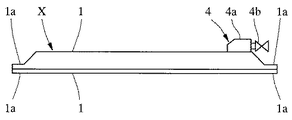
【図1】 本発明に係る二重遮水シートの1実施例の平面図である。
【図2】 図1の右側面図である。
【図3】 図1におけるA−A線断面図である。
【図4】 本発明に係る二重遮水シートの他の実施例の平面図である。
【図5】 所定間隔毎にニードルパンチされて連結されている対向する一対の上布と下布との間にベントナイトが挾持されている止水材の断面説明図である。
【図6】 透水用チューブが挿入されている透水用不織布の側面拡大説明図である。
【図7】 二重遮水シート内の空気を吸引する様子を示す説明図である。
【図8】 図1における二重遮水シートを吸引した後に、上布側の遮水シートを上面にして注入手段を法肩に位置させた状態で二重遮水シートを海面又は水面上に浮かべた状態を示す右側面説明図である。
【図9】 二重遮水シートの見かけ比重を海水又は水より大きくして二重遮水シートを海面下又は水面下に敷設した様子を示す右側面説明図である。
【符号の説明】
X 二重遮水シート
1 遮水シート
1a 端縁
1b 袋状部
2 止水材
2a ベントナイト
2b 上布
2c 下布
3 透水用不織布
3a 透水用チューブ
4 注入手段
4a 注入口
4b 注入用弁
5 吸引手段
5a 吸引口
5b 吸引用弁[0001]
BACKGROUND OF THE INVENTION
The present invention relates to a double water-impervious sheet to be laid at a final disposal site for waste, and after inhaling the air in the double water-impervious sheet and floating on the sea surface or water, water is injected into the double water-impervious sheet. The present invention relates to a method of laying a double water-impervious sheet that is sunk under the sea surface or under the water surface.
[0002]
[Prior art]
In conventional waste final disposal sites, water-blocking work was carried out simply by laying down vinyl chloride sheets, rubber sheets, asphalt coating sheets, polyolefin resin sheets, etc., but the water-blocking effect was maintained over a long period of time. In recent years, double water-impervious sheets in which a filler having a water-impervious effect is filled between these two water-impervious sheets have been widely used.
[0003]
The main filler used in this double water-impervious sheet is a cellulose / acrylonitrile polymer or acrylic acid / vinyl alcohol copolymer that does not deteriorate even if it swells due to infiltrated water and does not adversely affect the environment. In recent years, clay minerals such as bentonite based on montmorillonite, which swells by reacting with water and exhibits water-stopping properties, have been used. Yes.
This bentonite is used alone or in the form of a geosynthetic clay liner in which bentonite is held between an upper cloth made of woven or non-woven cloth and a lower cloth made of non-woven cloth. However, since this bentonite is generally used in a clay state in consideration of adhesion to a water-impervious sheet or upper and lower cloths, when used as a clay, the weight increases, resulting in poor efficiency of transportation, etc. If the water sheet is made relatively small and the weight is kept low, there is a drawback that the laying work efficiency is deteriorated.
[0004]
Therefore, by using bentonite as the particles instead of as clay, there are advantages such as even transport because it is lightweight becomes easy laying work, because there is no adhesion between the water shield sheet or vertical fabric laying When suspended in the course of work or laid on a slope or a vertical surface, bentonite has a disadvantage that it is biased downward between the double water-impervious sheets.
[0005]
In addition, when laying a double impermeable sheet under the sea surface or under the water surface, it is necessary to increase the apparent specific gravity of the double impermeable sheet than seawater or water, especially when laying under the sea surface, Since the specific gravity had to be increased, the conventional resin water-proof sheet could not be used.
[0006]
Furthermore, since the apparent specific gravity cannot be increased with the dry granular bentonite as it is, it is necessary to include water in the bentonite. Since it is lost, it is necessary to adjust the amount of water supplied according to the installation site. However, even if bentonite is pre-cured at the site, it is difficult to adjust such moisture for reasons such as drying before entering the double water-impervious sheet or air entering.
[0007]
[Problems to be solved by the invention]
The present invention solves the disadvantages and problems of the prior art described above, and it is lightweight and easy to carry and lay, but it can be suspended or laid on a slope or a vertical surface in the course of laying. There is no disadvantage that the water-stopping material is biased downward between the double water-impervious sheets and requires leveling work, etc., and the apparent specific gravity suitable for the installation location can be easily obtained, and after the installation, Providing a double water-impervious sheet that is self-repairing when the water sheet breaks, and a method for laying a double water-impervious sheet that lays the double impermeable sheet under the sea surface or under the water surface The task is to do.
[0008]
[Means for Solving the Problems]
As a result of various studies to solve the above-mentioned problems, the present inventors have provided a suction means on the water-impervious sheet, and if the air in the bag-like part is sucked from the suction means to reduce the pressure, Even if the bentonite as the filled water-stopping material is in the form of particles, it can be prevented from being biased in the double water-impervious sheet, and a water-permeable tube is inserted over substantially the entire longitudinal direction of the water-stopping material. If water is injected from the injection means provided on the water-impervious sheet in a reduced pressure state while the nonwoven fabric for water permeability is placed in a reduced pressure state, the double water-impervious sheet is in a reduced pressure state. The double waterproof sheet according to the present invention was completed by investigating that the apparent specific gravity of the double waterproof sheet can be easily changed through the entire top cover of the waterproof material in a short time. .
[0009]
In addition, if the air in the double water-impervious sheet is sucked and floated on the sea surface or the water surface, water is injected into the double water-impervious sheet and submerged under the sea surface or below the water surface. Since there is almost no air in the seat, the apparent specific gravity can be increased with a small amount of water, so that the double water-impervious sheet can be submerged under the sea surface or under the water surface without damaging the self-healing properties of bentonite. The apparent specific gravity can be made, and even when air remains in the double water-impervious sheet, the injection means for injecting water and the suction means for sucking air in the double water-impervious sheet are water-impervious. If a double water-impervious sheet provided near the same edge of the sheet is used, the air in the double water-impervious sheet rises upward when the double water-impervious sheet is submerged under the sea surface or under the water surface. Therefore, the present invention has been studied to find out that it is necessary to suck the air. It was completed the double water barrier sheet laying methods.
[0010]
That is, the present invention provides a bag-shaped portion in which all four edges of a pair of opposed rectangular water-proof sheets are in close contact with each other and sealed, and is made of a woven or non-woven fabric having substantially the same size as the bag-shaped portion. A water-stopping material in which granular bentonite is held by a cloth and a lower cloth made of non-woven cloth, and both cloths are connected by needle punching at a predetermined interval, is over the water-permeable non-woven cloth in which a water-permeable tube is inserted. over substantially the entire longitudinal direction of the fabric is inserted in a state of being heavy wear, inlet from the injection valve to the formation Ri permeability for nonwovens by injecting water through a water permeable non-woven fabric on the water stopping material An injection means for spreading water over the entire cloth is provided in the vicinity of the longitudinal edge of the water-impervious sheet on the upper cloth side and at a position facing the water-permeable nonwoven fabric. Suction means consisting of a suction port for sucking air and a suction valve A double water-impervious sheet, characterized in that provided in the water shield sheets,
In this double water-impervious sheet, the double water-impervious sheet provided near the edge where the suction means is provided with the injection means,
A pair of rectangular water-proof sheets facing each other, the edges of the four circumferences are all in close contact with each other and sealed in a sealed bag-like part and have a size substantially the same as that of the bag-like part. Granular bentonite is held between the cloths, and both cloths are needle punched at predetermined intervals and connected to each other. Watarura over and go water across upper cloth waterproof material through the heavy wear is not the be inserted in a state Note inlet and injection valve and by injecting water into the formation Ri permeability for nonwovens from permeable non-woven fabric A suction port for sucking air in the bag-like portion, and injecting means for causing the air in the bag-like portion to be provided in the vicinity of the longitudinal edge of the water-impervious sheet on the upper cloth side and at the position facing the nonwoven fabric for water permeability A suction means consisting of a suction valve is provided on the waterproof sheet on the upper fabric side. After sucking the air in the bag-like part from the suction means of the double waterproof sheet, the double waterproof sheet is placed in the state where the injection means is located on the shoulder with the upper sheet side waterproof sheet as the upper surface. The amount of water that floats on the sea surface or water surface and at least part of the bentonite of the water-stopping material remains granular is injected from the injection means into the water- permeable nonwoven fabric so that the apparent specific gravity of the double water-impervious sheet is greater than seawater or water. A double impermeable sheet laying method under the sea surface or under the water surface,
In this method of laying a double water-impervious sheet, a double water-impervious sheet in which the injection means and the suction means are provided in the vicinity of the same edge of the water-impervious sheet is used. The present invention relates to a method for laying a double water-impervious sheet that sucks air from the suction means that remains in the bag-like portion that has sunk down and has risen to the shoulder after a predetermined time has elapsed.
[0011]
DETAILED DESCRIPTION OF THE INVENTION
Hereinafter, the double water-impervious sheet according to the present invention and the laying method thereof will be described in detail with reference to the drawings.
1 is a plan view of an embodiment of a double water-impervious sheet according to the present invention, FIG. 2 is a right side view of FIG. 1, FIG. 3 is a cross-sectional view taken along line AA in FIG. FIG. 5 is a plan view of another embodiment of the double water-impervious sheet, FIG. 5 is a water stop in which bentonite is held between a pair of upper and lower cloths that are needle punched and connected at predetermined intervals. FIG. 6 is an enlarged side view of a water-permeable nonwoven fabric in which a water-permeable tube is inserted, FIG. 7 is an explanatory view showing how air in a double water-impervious sheet is sucked, and FIGS. FIG. 8 is a right side explanatory view showing an embodiment of the double water-impervious sheet laying method according to the present invention for each step, and FIG. 8 shows the upper cloth side after sucking the double water-impervious sheet in FIG. With the double impervious sheet floating on the sea surface or water surface with the injection means positioned on the shoulder with the water impervious sheet as the upper surface Be explanatory right side view and FIG. 9 is an explanatory right side view showing a state in which the apparent specific gravity of the double water shield sheets laid double water barrier sheet is greater than the sea water or water under subsea or surface.
[0012]
In the drawings, X is a double water-impervious sheet according to the present invention laid at a waste final disposal site or the like, and has a structure in which a water-
[0013]
[0014]
2 is a
[0015]
Further, the water-
[0016]
4 injection means for Watarura go water across
[0017]
5 is a suction means provided on the water-
[0018]
A method for laying a double water-impervious sheet according to the present invention having such a structure will be described with reference to FIGS.
In order to carry out the method of laying the double water-impervious sheet according to the present invention, for example, as shown in FIG. 7, a
[0019]
Thus, the air in the bag-
[0020]
Next, in order to inject water from the injection means 4 into the double impermeable sheet X, although not shown, the
[0021]
The water thus injected passes through the water
[0022]
If the
[0023]
【The invention's effect】
The double water-impervious sheet according to the present invention as described in detail above is a double water-impervious sheet in which a waterproof material is simply filled between the double water-impervious sheets like the conventional double water-impervious sheet. Unlike the water-impervious sheet, the water-impervious sheet is provided with suction means, so that the double water-impervious sheet is depressurized by using the suction means and the inner surface of the water-impervious sheet and the water-permeable material are filled. Since the shape of the double water-impervious sheet can be maintained by keeping the nonwoven fabric in close contact, it is filled even when suspended or laid on a slope or vertical surface in the process of laying Since there is no disadvantage that the water-stopping material is biased downward between the double water-impervious sheets, large work processes such as leveling work can be reduced, and there is almost air in the double water-impervious sheet. You can increase the apparent specific gravity with a small amount of water. In addition, it is possible to easily make the double water-impervious sheet have an apparent specific gravity suitable for the place where it is laid, and in the longitudinal direction on the upper fabric of the water-stopping material in which granular bentonite is held between the upper fabric and the lower fabric Since the water-permeable nonwoven fabric into which the water-permeable tube is inserted is overlaid, the water injected from the injection means is injected into the entire upper fabric of the water-stopping material through the water-permeable nonwoven fabric. Therefore, it is a double water-impervious sheet that is particularly useful when laying under the sea or water.
[0024]
And the laying method of the double water-impervious sheet according to the present invention is that the air in the double water-impervious sheet is sucked and floated on the sea surface or the water surface, and then water is injected into the double water-impervious sheet to below the sea surface or the water surface. It is a laying method that sinks underneath, and since it does not contain water when it floats on the sea surface or water surface, it is lightweight and because it is in a decompressed state, the waterproof material in the double water-impervious sheet will not be biased Work such as hanging when the double impermeable sheet floats on the sea surface or the water surface can be easily performed, and when water is injected and submerged under the sea surface or under the water surface, a non-woven fabric for water permeability is provided as a water passage Since the double impermeable sheet is also in a reduced pressure state, water can be spread over at least the entire upper surface of the double impermeable sheet in a short time, so that the laying operation can be performed efficiently. Furthermore, since it is difficult to change the apparent specific gravity of the ready-made double water-impervious sheet, it was necessary to place a sandbag or the like in order to sink the double water-impervious sheet under the sea surface or the water surface. By using the double impermeable sheet laying method according to the present invention, it is easy to make the apparent specific gravity suitable for the laying place just by injecting water until the double impermeable sheet sinks below the sea surface or below the water surface. It can be done.
In addition, even when air remains in the double water-impervious sheet, since the suction means is provided, the air that has risen upward in the bag-like portion after laying can be sucked, Not only can a part of the sheet be lifted but also a phenomenon in which an uneven load acts on a portion where the water-impervious sheet is deformed due to the presence of air and breaks does not occur.
[0025]
The industrial value of the double water-impervious sheet and its laying method according to the present invention that exhibits such various effects is very large.
[Brief description of the drawings]
FIG. 1 is a plan view of one embodiment of a double water-impervious sheet according to the present invention.
FIG. 2 is a right side view of FIG.
FIG. 3 is a cross-sectional view taken along line AA in FIG.
FIG. 4 is a plan view of another embodiment of the double water-impervious sheet according to the present invention.
FIG. 5 is an explanatory cross-sectional view of a water stop material in which bentonite is held between a pair of opposed upper and lower cloths that are needle punched and connected at predetermined intervals.
FIG. 6 is an enlarged side view of a water permeable nonwoven fabric in which a water permeable tube is inserted.
FIG. 7 is an explanatory view showing a state of sucking air in the double water-impervious sheet.
FIG. 8 After the double water-impervious sheet in FIG. 1 is sucked, place the double water-impervious sheet on the sea surface or water surface with the upper cloth-side water-impervious sheet on the upper surface and the injection means positioned on the shoulder. It is right side explanatory drawing which shows the state which floated.
FIG. 9 is an explanatory diagram on the right side view showing a state in which the apparent density of the double water-impervious sheet is made larger than seawater or water and the double impermeable sheet is laid under the sea surface or under the water surface.
[Explanation of symbols]
X Double
1a Edge
1b Bag-
2a Bentonite
2b Top cloth
4a Inlet
5a Suction port
5b Suction valve
Claims (4)
Priority Applications (1)
| Application Number | Priority Date | Filing Date | Title |
|---|---|---|---|
| JP2002029545A JP4077207B2 (en) | 2002-02-06 | 2002-02-06 | Double impermeable sheet and its laying method |
Applications Claiming Priority (1)
| Application Number | Priority Date | Filing Date | Title |
|---|---|---|---|
| JP2002029545A JP4077207B2 (en) | 2002-02-06 | 2002-02-06 | Double impermeable sheet and its laying method |
Publications (2)
| Publication Number | Publication Date |
|---|---|
| JP2003225630A JP2003225630A (en) | 2003-08-12 |
| JP4077207B2 true JP4077207B2 (en) | 2008-04-16 |
Family
ID=27750178
Family Applications (1)
| Application Number | Title | Priority Date | Filing Date |
|---|---|---|---|
| JP2002029545A Expired - Fee Related JP4077207B2 (en) | 2002-02-06 | 2002-02-06 | Double impermeable sheet and its laying method |
Country Status (1)
| Country | Link |
|---|---|
| JP (1) | JP4077207B2 (en) |
Families Citing this family (2)
| Publication number | Priority date | Publication date | Assignee | Title |
|---|---|---|---|---|
| JP2005230638A (en) * | 2004-02-18 | 2005-09-02 | Waatekkusu:Kk | Impervious sheet |
| JP4565550B2 (en) * | 2004-07-07 | 2010-10-20 | 鹿島建設株式会社 | Water shielding material injection type water shielding system |
-
2002
- 2002-02-06 JP JP2002029545A patent/JP4077207B2/en not_active Expired - Fee Related
Also Published As
| Publication number | Publication date |
|---|---|
| JP2003225630A (en) | 2003-08-12 |
Similar Documents
| Publication | Publication Date | Title |
|---|---|---|
| US5564864A (en) | Clay liner for steep slopes | |
| CA2683616C (en) | Dust-removal managing pit | |
| US20030059258A1 (en) | Under drainage method for building using perforated drain pipes | |
| CN110845109B (en) | Sludge treatment system adopting horizontal drainage plate and geotextile vacuum preloading method and construction method thereof | |
| CN103628468A (en) | Foundation treatment method adopting water penetration pile in combination with vacuum preloading | |
| JP5117793B2 (en) | Underground water tank | |
| JP2009046918A (en) | Construction method for improving soft ground by vacuum consolidation | |
| KR20000016216A (en) | System and method for blocking leachate by using diving back flow tank | |
| JP2006291645A (en) | Improved structure of soft ground and its improving method | |
| JP4077207B2 (en) | Double impermeable sheet and its laying method | |
| CN102704458A (en) | Sand-free cushion layer vacuum-surcharge preloading reinforcement device and method for soft ground | |
| US9309639B2 (en) | System, method, connector and geocomposite for fluid recovery | |
| CN104895039B (en) | Full water construction method of soft foundation | |
| CN213508414U (en) | Soft soil foundation consolidation drainage concreties construction equipment | |
| EP1064432B1 (en) | Consolidation method for soil layers with low permeability | |
| CN210712967U (en) | Impervious anti structure that floats of basement | |
| JP5234748B2 (en) | Piping unit and dredging system for underground irrigation using the same | |
| CN210482215U (en) | Anti-seepage drainage and exhaust structure suitable for flat reservoir basin | |
| CN106638549B (en) | A kind of preset sand drain in hydraulic reclamation area-plastic draining board composite, water-drain decontamination plant | |
| CN209429178U (en) | Seepage proof curtain and guide seepage control system | |
| JP2735706B2 (en) | Bentonite waterproofing method and waterproof mat | |
| JP4080299B2 (en) | Double waterproof sheet | |
| CN110485375A (en) | Antiseepage drainage exhaust structure suitable for Wall in Plain Reservoir library basin | |
| CN203821457U (en) | Rock-soil base plane liquid storage tank high-density polyethylene (HDPE) membrane leakproof structure | |
| KR20070006312A (en) | A one body drainage seat with protrusion |
Legal Events
| Date | Code | Title | Description |
|---|---|---|---|
| A711 | Notification of change in applicant |
Free format text: JAPANESE INTERMEDIATE CODE: A711 Effective date: 20040727 |
|
| A521 | Request for written amendment filed |
Free format text: JAPANESE INTERMEDIATE CODE: A821 Effective date: 20040727 |
|
| A621 | Written request for application examination |
Free format text: JAPANESE INTERMEDIATE CODE: A621 Effective date: 20050202 |
|
| A977 | Report on retrieval |
Free format text: JAPANESE INTERMEDIATE CODE: A971007 Effective date: 20061225 |
|
| A131 | Notification of reasons for refusal |
Free format text: JAPANESE INTERMEDIATE CODE: A131 Effective date: 20071106 |
|
| A521 | Request for written amendment filed |
Free format text: JAPANESE INTERMEDIATE CODE: A523 Effective date: 20071227 |
|
| TRDD | Decision of grant or rejection written | ||
| A01 | Written decision to grant a patent or to grant a registration (utility model) |
Free format text: JAPANESE INTERMEDIATE CODE: A01 Effective date: 20080129 |
|
| A61 | First payment of annual fees (during grant procedure) |
Free format text: JAPANESE INTERMEDIATE CODE: A61 Effective date: 20080131 |
|
| R150 | Certificate of patent or registration of utility model |
Free format text: JAPANESE INTERMEDIATE CODE: R150 Ref document number: 4077207 Country of ref document: JP Free format text: JAPANESE INTERMEDIATE CODE: R150 |
|
| FPAY | Renewal fee payment (event date is renewal date of database) |
Free format text: PAYMENT UNTIL: 20110208 Year of fee payment: 3 |
|
| FPAY | Renewal fee payment (event date is renewal date of database) |
Free format text: PAYMENT UNTIL: 20140208 Year of fee payment: 6 |
|
| R250 | Receipt of annual fees |
Free format text: JAPANESE INTERMEDIATE CODE: R250 |
|
| R250 | Receipt of annual fees |
Free format text: JAPANESE INTERMEDIATE CODE: R250 |
|
| RD03 | Notification of appointment of power of attorney |
Free format text: JAPANESE INTERMEDIATE CODE: R3D03 |
|
| R250 | Receipt of annual fees |
Free format text: JAPANESE INTERMEDIATE CODE: R250 |
|
| R250 | Receipt of annual fees |
Free format text: JAPANESE INTERMEDIATE CODE: R250 |
|
| R250 | Receipt of annual fees |
Free format text: JAPANESE INTERMEDIATE CODE: R250 |
|
| LAPS | Cancellation because of no payment of annual fees |