JP4075996B2 - Lamp socket and lighting fixture - Google Patents
Lamp socket and lighting fixture Download PDFInfo
- Publication number
- JP4075996B2 JP4075996B2 JP2004102957A JP2004102957A JP4075996B2 JP 4075996 B2 JP4075996 B2 JP 4075996B2 JP 2004102957 A JP2004102957 A JP 2004102957A JP 2004102957 A JP2004102957 A JP 2004102957A JP 4075996 B2 JP4075996 B2 JP 4075996B2
- Authority
- JP
- Japan
- Prior art keywords
- lamp
- pair
- contact
- socket
- insertion hole
- Prior art date
- Legal status (The legal status is an assumption and is not a legal conclusion. Google has not performed a legal analysis and makes no representation as to the accuracy of the status listed.)
- Expired - Fee Related
Links
Images


Landscapes
- Connecting Device With Holders (AREA)
Description
本発明は、ランプソケット及びこのランプソケット使用の照明器具に関するものである。 The present invention relates to a lamp socket and a lighting fixture using the lamp socket.
従来のランプソケットは、ソケット筐体と、該ソケット筐体に移動可能に収納される摺動体と、該摺動体に収納されランプ端子と当接する接触金具と、ソケット筐体に収納され、一端に接触金具が接続される接続部を備え、他端がソケット筐体に係止される導電金具とを有し、接続部に接触金具が挿入される係合孔を設けるとともに、係合孔の周端であって、ランプ装着時に、ランプ端子の挿入方向と略垂直方向であり接触金具が回動して動く方向に弾性を有する一対の切り起し片を対向させて一体で形成し、切り起し片により接触金具を挟持させた(例えば、特許文献1参照)。
特許文献1のランプソケットは、接触金具と導電金具との接続信頼性は向上したが、ランプをランプソケットに装着するとき、ランプの軸方向が傾いて装着された場合等、一対のランプ口金端子のうち、一方のランプ口金端子と接触金具との接続は確保されても、他方のランプ口金端子と接触金具との接続は不充分となるというランプ口金端子と接触金具との接続信頼性には問題がある。
The lamp socket of
本発明は、上記のような課題を解決するためになされたもので、たとえランプがランプソケットに傾いて挿入されても、ランプ口金端子と接触金具との接続が充分となり、接続信頼性が向上するランプソケットを得ることを目的とする。
また、組立性を向上できるランプソケットを得ることを目的とする。
The present invention has been made to solve the above-described problems. Even when the lamp is inserted into the lamp socket at an angle, the connection between the lamp base terminal and the contact fitting becomes sufficient, and the connection reliability is improved. The purpose is to obtain a lamp socket.
It is another object of the present invention to obtain a lamp socket that can improve assemblability.
本発明に係るランプソケットは、前面に開口部を備えたソケット筐体と、ランプ端部から突起する円筒状のランプ口金が挿入される挿入孔を前部に備え、前記ソケット筐体の前記開口部に移動可能に収容された受け体と、前記受け体の挿入穴の中心側に設置された一対の接触金具と、前記受け体の挿入穴内で、内壁に設置された弾性変形可能な一対のランプ保持部材と、前記接触金具と外部電線とを電気的に接続する導電部材と、照明器具に取付ける取付け部とを有し、前記各ランプ保持部材と前記各接触金具とを対向させ、一体形成し、前記一対のランプ保持部材間の間隔を前記円筒状のランプ口金よの外径より小さくし、前記ランプ口金を前記受け体の前記挿入穴に挿入することにより、前記円筒状のランプ口金の内壁の一対の口金端子を前記挿入穴の中心部に設置された一対の接触金具に接触させるとともに、前記一対のランプ保持部材が弾性変形し、前記ランプ口金を保持するものである。
The lamp socket according to the present invention includes a socket housing having an opening on the front surface and an insertion hole into which a cylindrical lamp base protruding from the lamp end is inserted, and the opening of the socket housing And a pair of contact fittings installed on the center side of the insertion hole of the receiver, and a pair of elastically deformable installed on the inner wall in the insertion hole of the receiver A lamp holding member; a conductive member that electrically connects the contact fitting and the external wire; and a mounting portion that is attached to a lighting fixture. The lamp holding member and the contact fitting face each other and are integrally formed. Then, the interval between the pair of lamp holding members is made smaller than the outer diameter of the cylindrical lamp base, and the lamp base is inserted into the insertion hole of the receiving body, so that the cylindrical lamp base A pair of cap terminals on the inner wall Together brought into contact with a pair of contact fittings installed in the center of the insertion hole, the pair of lamp holding member in which elastic deformation, holding the lamp base.
本発明に係るランプソケットは、一対のランプ保持部材間の間隔を円筒状のランプ口金の外径より小さくし、ランプ口金を受け体の挿入穴に挿入することにより、円筒状のランプ口金の内壁の一対の口金端子を挿入穴の中心側に設置された一対の接触金具に接触させるとともに、一対のランプ保持部材が弾性変形し、ランプ口金を保持するので、ランプが傾いて挿入されても、一対の口金端子は確実にそれぞれの接触金具に接触し、電気的接続信頼性を向上できる。 The lamp socket according to the present invention has an inner wall of a cylindrical lamp base by making the distance between the pair of lamp holding members smaller than the outer diameter of the cylindrical lamp base and inserting the lamp base into the insertion hole of the receiving body. The pair of base terminals are brought into contact with a pair of contact fittings installed on the center side of the insertion hole, and the pair of lamp holding members are elastically deformed to hold the lamp base. The pair of base terminals can be surely brought into contact with the respective contact fittings to improve the electrical connection reliability.
実施の形態1.
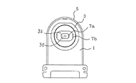
図1は、本発明の実施の形態1におけるランプソケットを示す分解斜視図であり、図2は、図1のランプソケットの正面図であり、図3は、図1のランプソケットの導電金具を示す斜視図であり、図4は、図1のランプソケットにランプ装着時のランプ口金端子と接触金具との接続及びランプ保持部材によるランプ口金の保持を説明する断面図であり、図5は、図1のランプソケットのランプ装着前後の導電金具及びコイルバネの状態を説明する断面図である。
これらの図において、本ランプソケットは、ソケット本体1、ソケット本体1に背面側から挿入され、ソケット本体1の前部の開口部1aから前部が出るように、前後方向(ランプ挿入方向)に移動可能に取り付けられる受け体3、一対の導電金具7及び受け体3とソケットカバー5間に設置され、受け体3を前方に付勢する一対のコイルバネ12等で構成される。
1 is an exploded perspective view showing a lamp socket according to
In these figures, the lamp socket is inserted into the
ソケット本体1は、合成樹脂製であり、前面側に開口部1aを備え、背面側からソケットカバー5で覆い、内部に収容部を形成するソケット筐体となる。
受け体3は、合成樹脂製であり、ソケット本体1の開口部1aに挿入され、前後方向に摺動自在とされるもので、前面に開口する挿入穴3aを有し、この挿入穴3aにランプ口金11aが挿入される。また、挿入穴3aの中央には、前面から見て断面が矩形状の部材が後部より突出するように設けられ、仕切部3dを形成する。前面から見て、仕切部3dの左右の側壁には、導電金具7の接触金具7aを収容する凹部よりなる接触金具収納部3cが形成されている。また、挿入穴3aの内壁で、仕切部3dの左右の接触金具収納部3cに対向する側壁に導電金具7のランプ保持部材であるランプ保持金具7bを収容する凹部よりなるランプ保持金具収納部3bが形成されている。即ち、一対の接触金具7aとそれぞれに対向するランプ保持金具7bとが、それぞれの収納部に収納される。
The
The
導電金具7は、板状の導電部材からなり、図3に示すように一体ものとして、打ち抜き及び曲げにより加工したものである。導電金具7は、上部にくの字状の接触金具7aとくの字状のランプ保持金具7bとをくの字状の屈曲凸部を対向させた全体的に略U字状体の対向部を形成し、また、下部に外部電線を接続する鎖錠片7eを有する連結端子部7dを形成し、これらを接続部であるL字接続部7cで連結する。図1に示すように、導電金具7は一対を組として使用する。
導電金具7は、上部の接触金具7aを受け体3の背面側から挿入し、仕切部3dの接触金具収納部3cに収納する。同時にランプ保持金具7bもランプ保持金具収納部3bに収納する。また、導電金具7の下部の連結端子部7dは、ソケット筐体下部の所定収納部に収納する。そして、これらの間のソケット筐体内に、接続部であるL字接続部7cを収納する。
The
The
一対のコイルバネ12は、ソケットカバー5の背面側の内壁と受け体3の間に設置され、受け体3を前面側に付勢する。
このように、ソケット本体に受け体3、一対の導電金具7及び一対のコイルバネを収納させソケットカバー5で背面側から覆い、ランプソケットを組立てる。
The pair of
In this manner, the
このように組立てたランプソケットへの蛍光ランプの装着を説明する。
図4(a)は、ランプ装着前の状態であり、図4(b)は、ランプ装着時の状態を示す。
ランプ11のランプ口金11aは、ランプ端部から突起する円筒状のもので、外側の口金側壁部11bに対して内側に対向する一対の口金端子11cを有する。ランプ口金11aを受け体3の挿入穴3aに一対の口金端子11cが仕切部3dで両側に分かれる様に挿入する。このとき、接触金具7aは、くの字状の屈曲凸部が外側になるように接触金具収納部3cに収納固定され、また、ランプ保持金具7bは、くの字状の屈曲凸部が内側になるようにランプ保持金具収納部3bに収納固定され、仕切部3dに対してそれぞれの側で、接触金具7aとランプ保持金具7bとの屈曲凸部同士が対向する。
また、一対のランプ保持部材であるランプ保持金具7bの屈曲凸部間の間隔を円筒状のランプ口金11aの外径より小さくする。
そこで、ランプ口金11aを受け体3の挿入穴3aに挿入することにより、一対のランプ保持金具7bが弾性変形し、ランプ口金11aを保持することができ、円筒状のランプ口金11aの内壁の一対の口金端子11cを挿入穴3aの中心側に設置された一対の接触金具7aに接触させる。即ち、たとえ、蛍光ランプが傾いて挿入されても一対の口金端子11cは両方共確実に接触金具7aに接触する。
さらに、仕切部3dのそれぞれの側で、接触金具7aとランプ保持金具7bの屈曲凸部間の距離(隙間)をランプ口金11aの内側の口金端子11cの内壁と外側の口金側壁部11bの外壁間の距離(ランプ口金厚み)より小さくする。即ち、接触金具7aとランプ保持金具7bとの挿入穴3a内での間隔をランプ口金11aの内側の口金端子11cと外側の口金側壁部11bとの距離を小さくする。そこで、ランプ口金11aを挿入するとき、接触金具7aとランプ保持金具7bとの間隔が広がり、弾性的にランプ口金11aを接触金具7aの屈曲凸部とランプ保持金具7bの屈曲凸部が挟持するので、口金端子11cは確実に接触金具7aに接触する。即ち、たとえ、蛍光ランプが曲がって挿入されても一対の口金11cは両方共確実に接触金具7aに接触する。
The mounting of the fluorescent lamp to the lamp socket assembled in this way will be described.
4A shows a state before the lamp is mounted, and FIG. 4B shows a state when the lamp is mounted.
The
Further, the interval between the bent convex portions of the lamp holding
Therefore, by inserting the
Further, on each side of the
また、一端部に接触金具7aとランプ保持部材であるランプ保持金具7bとの対向部を形成し、他端部に鎖錠片7eを有する速結端子部7dを形成し、両端部を接続部で接続する一体に形成した導電金具7を形成し、一端部の接触金具7aとランプ保持金具7bとを受け体3の挿入穴3aに設置し、接続部を筐体内に収納し、他端部を筐体の下部に収納したので、ランプ11の口金端子11cと外部電線との電気的接続を、一体に形成した導電金具7で行うことができ、複数の部品の接続による場合の接触抵抗の増加、接続の信頼性の低下等の問題が解消できる。また、一体化した導電金具7は、切り抜き、曲げ加工で製作できるので製作が容易である。さらに、一体化した導電金具7をソケット筐体に組み込むことは容易であり、ランプソケットの組立てが容易となる。
Moreover, the opposing part of the contact metal fitting 7a and the lamp holding
本ランプソケットは、図1に示すように、ソケットカバー5の下部に照明器具に取付ける取付け部8を形成している。ランプソケット組立て後、この取付け部8のスリット溝により照明器具に取付ける。本ランプソケット使用の照明器具は、ランプ口金端子11cの電気的接続信頼性の高い照明器具となる。
図4(b)に本ランプソケットに蛍光ランプ11を装着した状態を示すが、この図は、ランプ口金11aをランプ保持金具7bで保持する状態を説明するものであり省略しているが、コイルバネ12は、ランプ装着によりランプ11からの押圧により縮む。この状態を図5に示す。図5(a)のランプ装着前の伸びた状態からランプ装着により、図5(b)に示すように縮む。同時にL字接続部は、上部の前方への傾斜から垂直状体となる。
As shown in FIG. 1, the lamp socket has an attachment portion 8 attached to a lighting fixture at the lower part of the
FIG. 4B shows a state in which the fluorescent lamp 11 is mounted on the lamp socket. This figure is for explaining a state in which the
導電金具7は、導電金属板を加工した一体ものとしてきたが、一体ものに限らず別体の部品を接続しても良く、接触金具7aを導電部材で接続して外部電線との電気的接続がとれれば良い。また、ランプ保持部材であるランプ保持金具7bは、別体の非金属でも良く、材質的に弾性体又は形状として弾性体としたもので、ランプ装着において、弾性変形してランプ口金11aを挿入させ、ランプ口金11aを保持するものであれば良い。また、接触金具7a、ランプ保持金具7bは、くの字形状に限定せず、接触金具7aはランプ口金端子11cと電気的に接続するものであり、また、ランプ保持金具7bはランプ口金11aを保持するものであれば良い。
さらに、ランプ保持部材であるランプ保持金具7bは、挿入穴3aの内壁に対向して、少なくとも一対は必要であり、二以上設けることによりランプ口金11aの保持は、より確実となる。
The
Furthermore, at least a pair of
本ランプソケットは、接触金具7aとランプ保持金具7bとを導電材料で対向するように一体形成し、この一体形成部を外部電線と接続する導電部材と接続しても、口金端子11cを接触金具7aに接触させ、ランプ口金11aをランプ保持金具7bで保持させるので、ランプ11が傾いて挿入されても、一対の口金端子11cは確実にそれぞれの接触金具7aに接触し、電気的接続信頼性を向上できる。
In this lamp socket, the contact fitting 7a and the lamp holding fitting 7b are integrally formed so as to face each other with a conductive material, and the
実施の形態2.
実施の形態2のランプソケットは、実施の形態1のランプソケットにおいて、導電金具7を一部変形させ、ランプ保持金具7bとして特別の部材を設置しないようにしたものである。その他の構成は実施の形態1のランプソケットと同様であるので、以下主として、相違点を説明する。
Embodiment 2. FIG.
The lamp socket according to the second embodiment is obtained by partially deforming the
図6に本実施の形態の一対の導電金具7を示す。この導電金具7は一体形成されるが、ランプ保持金具7bを有していない。その他は、実施の形態1の導電金具7と同様である。また、受け体3の挿入穴3a内の仕切部3dの左右の側壁の接触金具収納部3cに接触金具7aを収納する。その他受け体3及びランプ筐体への取付けは、実施の形態1と同様である。
本ランプソケットにおいては、一対の接触金具7aの最外側部間の距離、即ち、図6の一対の接触金具7aの屈曲凸部間の距離を円筒状のランプ口金11aの内壁の一対の口金端子11c間の間隔より大きくする。このようにすることで、ランプ口金11aを受け体3の挿入穴3aに挿入することにより、一対の接触金具7aが弾性変形しランプ口金11aを保持し、また、一対の接触金具7aが、それぞれ、円筒状のランプ口金11aの内壁の一対の口金端子11cと接触する。
このようにしても、実施の形態1のランプソケットと同様にランプ11が傾いて挿入されても、一対の口金端子11cは確実にそれぞれの接触金具7aに接触し、電気的接続信頼性を向上できる。
また、複数の部品の接続による場合の接触抵抗の増加、接続の信頼性の低下等の問題が解消でき、一体化した導電金具7をソケット筐体に組み込むことは容易であり、ランプソケットの組立てが容易となるのも同様である。さらに、一体化した導電金具7は、切り抜き、曲げ加工で製作でき、ランプ保持金具を有さないので、一層製作が容易である。また、接触金具7a、くの字形状に限定しない等も実施の形態1と同様である。
FIG. 6 shows a pair of
In this lamp socket, the distance between the outermost portions of the pair of
Even if it does in this way, even if the lamp | ramp 11 is inclined and inserted similarly to the lamp socket of
Further, problems such as an increase in contact resistance and a decrease in connection reliability due to the connection of a plurality of components can be solved, and it is easy to incorporate the integrated
1a 開口部、3 受け体、3a 挿入穴、7 導電金具、7a 接触金具、7b ランプ保持部材、7d 速結端子部、7e 鎖錠片、8 取付け部、11a ランプ口金、11c ランプ口金の口金端子。
DESCRIPTION OF SYMBOLS 1a Opening part, 3 Receiver body, 3a Insertion hole, 7 Conductive metal fitting, 7a Contact metal fitting, 7b Lamp holding member, 7d Fast connection terminal part, 7e Locking piece, 8 Mounting part, 11a Lamp cap, 11c Lamp cap base terminal .
Claims (3)
前記一対のランプ保持部材間の間隔を前記円筒状のランプ口金の外径より小さくし、前記ランプ口金を前記受け体の前記挿入穴に挿入することにより、前記円筒状のランプ口金の内壁の一対の口金端子を前記挿入穴の中心部に設置された一対の接触金具に接触させるとともに、前記一対のランプ保持部材が弾性変形し、前記ランプ口金を保持することを特徴とするランプソケット。 A socket housing having an opening on the front surface and an insertion hole into which a cylindrical lamp base protruding from the lamp end portion is inserted at the front, and is movably accommodated in the opening of the socket housing A receiver, a pair of contact fittings installed on the center side of the insertion hole of the receptacle, a pair of elastically deformable lamp holding members installed on an inner wall in the insertion hole of the receiver, and the contact fitting A conductive member that electrically connects the external electric wire, and a mounting portion that is attached to the lighting fixture, the lamp holding members and the contact fittings are opposed to each other, and are integrally formed.
A distance between the pair of lamp holding members is made smaller than an outer diameter of the cylindrical lamp base, and the lamp base is inserted into the insertion hole of the receiving body, whereby a pair of inner walls of the cylindrical lamp base is formed. And a pair of contact fittings installed at the center of the insertion hole, and the pair of lamp holding members are elastically deformed to hold the lamp base.
Priority Applications (1)
| Application Number | Priority Date | Filing Date | Title |
|---|---|---|---|
| JP2004102957A JP4075996B2 (en) | 2004-03-31 | 2004-03-31 | Lamp socket and lighting fixture |
Applications Claiming Priority (1)
| Application Number | Priority Date | Filing Date | Title |
|---|---|---|---|
| JP2004102957A JP4075996B2 (en) | 2004-03-31 | 2004-03-31 | Lamp socket and lighting fixture |
Publications (3)
| Publication Number | Publication Date |
|---|---|
| JP2005293872A JP2005293872A (en) | 2005-10-20 |
| JP2005293872A5 JP2005293872A5 (en) | 2006-08-17 |
| JP4075996B2 true JP4075996B2 (en) | 2008-04-16 |
Family
ID=35326596
Family Applications (1)
| Application Number | Title | Priority Date | Filing Date |
|---|---|---|---|
| JP2004102957A Expired - Fee Related JP4075996B2 (en) | 2004-03-31 | 2004-03-31 | Lamp socket and lighting fixture |
Country Status (1)
| Country | Link |
|---|---|
| JP (1) | JP4075996B2 (en) |
Families Citing this family (2)
| Publication number | Priority date | Publication date | Assignee | Title |
|---|---|---|---|---|
| KR100734510B1 (en) | 2007-03-22 | 2007-07-03 | 엘티스 주식회사 | A fluorescent lamp |
| DE102008005823B4 (en) * | 2008-01-24 | 2013-12-12 | Bjb Gmbh & Co. Kg | Connection element for the electrical connection of an LED |
-
2004
- 2004-03-31 JP JP2004102957A patent/JP4075996B2/en not_active Expired - Fee Related
Also Published As
| Publication number | Publication date |
|---|---|
| JP2005293872A (en) | 2005-10-20 |
Similar Documents
| Publication | Publication Date | Title |
|---|---|---|
| US6743051B2 (en) | Electrical connector assembly | |
| KR101031118B1 (en) | Coaxial connector | |
| US9887481B2 (en) | Terminal, connector, and electrical connection apparatus | |
| JP4547282B2 (en) | Connector for automatic alignment | |
| JP2019153565A5 (en) | ||
| CN104081594B (en) | Light bulb holder and illuminator | |
| JP6709817B2 (en) | connector | |
| CN110649410A (en) | Terminal metal fitting | |
| JP4353433B2 (en) | connector | |
| JP4075996B2 (en) | Lamp socket and lighting fixture | |
| JP2007149602A (en) | Connector, receptacle for connector, and plug for connector | |
| JP2005123098A (en) | Joint connector | |
| JP2012059366A (en) | Connection structure of cable, electric connector for cable, and assembly of electric connector for cable | |
| JP2020537286A (en) | Plug connector parts | |
| JP2011181471A (en) | Card connector and method of manufacturing card connector | |
| US4938709A (en) | Connection terminals for rigid-wire loop cartridge light bulbs | |
| JP2008084878A (en) | Manufacturing method of electrical connector having fixing bracket | |
| JP4665491B2 (en) | Lamp socket | |
| JP6072629B2 (en) | Valve unit | |
| JP4485173B2 (en) | Memory card adapter | |
| KR102163934B1 (en) | Manufacturing method of connector terminal | |
| CN210607645U (en) | Plug wire connector | |
| JP2000113716A (en) | Lamp socket | |
| KR101687769B1 (en) | The led lamp device used in a vehicle interior light | |
| JP2002083641A (en) | Electrical connector |
Legal Events
| Date | Code | Title | Description |
|---|---|---|---|
| A521 | Written amendment |
Free format text: JAPANESE INTERMEDIATE CODE: A523 Effective date: 20060704 |
|
| A621 | Written request for application examination |
Free format text: JAPANESE INTERMEDIATE CODE: A621 Effective date: 20060704 |
|
| A977 | Report on retrieval |
Free format text: JAPANESE INTERMEDIATE CODE: A971007 Effective date: 20070625 |
|
| A131 | Notification of reasons for refusal |
Free format text: JAPANESE INTERMEDIATE CODE: A131 Effective date: 20070703 |
|
| A521 | Written amendment |
Free format text: JAPANESE INTERMEDIATE CODE: A523 Effective date: 20070809 |
|
| A131 | Notification of reasons for refusal |
Free format text: JAPANESE INTERMEDIATE CODE: A131 Effective date: 20071009 |
|
| A521 | Written amendment |
Free format text: JAPANESE INTERMEDIATE CODE: A523 Effective date: 20071122 |
|
| TRDD | Decision of grant or rejection written | ||
| A01 | Written decision to grant a patent or to grant a registration (utility model) |
Free format text: JAPANESE INTERMEDIATE CODE: A01 Effective date: 20080115 |
|
| A61 | First payment of annual fees (during grant procedure) |
Free format text: JAPANESE INTERMEDIATE CODE: A61 Effective date: 20080122 |
|
| R150 | Certificate of patent or registration of utility model |
Ref document number: 4075996 Country of ref document: JP Free format text: JAPANESE INTERMEDIATE CODE: R150 Free format text: JAPANESE INTERMEDIATE CODE: R150 |
|
| FPAY | Renewal fee payment (event date is renewal date of database) |
Free format text: PAYMENT UNTIL: 20110208 Year of fee payment: 3 |
|
| FPAY | Renewal fee payment (event date is renewal date of database) |
Free format text: PAYMENT UNTIL: 20120208 Year of fee payment: 4 |
|
| FPAY | Renewal fee payment (event date is renewal date of database) |
Free format text: PAYMENT UNTIL: 20130208 Year of fee payment: 5 |
|
| FPAY | Renewal fee payment (event date is renewal date of database) |
Free format text: PAYMENT UNTIL: 20130208 Year of fee payment: 5 |
|
| FPAY | Renewal fee payment (event date is renewal date of database) |
Free format text: PAYMENT UNTIL: 20140208 Year of fee payment: 6 |
|
| R250 | Receipt of annual fees |
Free format text: JAPANESE INTERMEDIATE CODE: R250 |
|
| R250 | Receipt of annual fees |
Free format text: JAPANESE INTERMEDIATE CODE: R250 |
|
| R250 | Receipt of annual fees |
Free format text: JAPANESE INTERMEDIATE CODE: R250 |
|
| LAPS | Cancellation because of no payment of annual fees |