JP4075908B2 - Drive device for slide hood in range hood - Google Patents
Drive device for slide hood in range hood Download PDFInfo
- Publication number
- JP4075908B2 JP4075908B2 JP2005142654A JP2005142654A JP4075908B2 JP 4075908 B2 JP4075908 B2 JP 4075908B2 JP 2005142654 A JP2005142654 A JP 2005142654A JP 2005142654 A JP2005142654 A JP 2005142654A JP 4075908 B2 JP4075908 B2 JP 4075908B2
- Authority
- JP
- Japan
- Prior art keywords
- hood
- slide
- drive device
- drive
- fixed
- Prior art date
- Legal status (The legal status is an assumption and is not a legal conclusion. Google has not performed a legal analysis and makes no representation as to the accuracy of the status listed.)
- Expired - Fee Related
Links
Images


Classifications
-
- F—MECHANICAL ENGINEERING; LIGHTING; HEATING; WEAPONS; BLASTING
- F24—HEATING; RANGES; VENTILATING
- F24C—DOMESTIC STOVES OR RANGES ; DETAILS OF DOMESTIC STOVES OR RANGES, OF GENERAL APPLICATION
- F24C15/00—Details
- F24C15/20—Removing cooking fumes
- F24C15/2078—Removing cooking fumes movable
- F24C15/2092—Removing cooking fumes movable extendable or pivotable
Landscapes
- Engineering & Computer Science (AREA)
- Chemical & Material Sciences (AREA)
- Combustion & Propulsion (AREA)
- Mechanical Engineering (AREA)
- General Engineering & Computer Science (AREA)
- Ventilation (AREA)
Description
本発明は、レンジフードの固定フードにスライド自在に設けられるスライドフードの駆動装置に関する。 The present invention relates to a drive device for a slide hood that is slidably provided on a fixed hood of a range hood.
従来、この種のレンジフードにおいて、可動フードを駆動ユニットにより駆動するものが知られている(例えば、特許文献1参照)。 Conventionally, in this type of range hood, a movable hood is driven by a drive unit (see, for example, Patent Document 1).
以下、そのレンジフードの駆動ユニットについて図8を参照しながら説明する。 Hereinafter, the drive unit of the range hood will be described with reference to FIG.
図に示すように、駆動ユニット101は、外筐102内に設けられた駆動モータ(図示せず)と、この駆動モータにて回転されるボルト103と、このボルト103に、接続された駆動駒104からなり、駆動モータの運転によりボルト103が回動し駆動駒104が前後に移動する。そして、駆動駒104は可動フード部105と連結ピン106を介して接合され、排気用送風機および給気用送風機(図示せず)と連動するように設けられている。
このような従来のレンジフードに設けられる駆動ユニット101は、外筐102に設けられる駆動モータと、ボルト103および駆動駒104の各部材はいちいち外筐102に組み込まなければならないので、組立性およびメンテナンス性が悪いという課題があり、駆動ユニット101の各部材を一体に設けてユニット化を図り、組立性およびメンテナンス性の向上を図ることが要求されている。
In the
本発明は、このような従来の課題を解決するものであり、駆動ユニットを一枚の板材に配設しユニット化して組立性およびメンテナンス性の向上を図ることのできるレンジフードにおけるスライドフードの駆動装置を提供することを目的としている。 The present invention solves such a conventional problem, and drives a slide hood in a range hood in which a drive unit is arranged on a single plate member to be unitized to improve assembly and maintenance. The object is to provide a device.
本発明のレンジフードにおけるスライドフードの駆動装置は、上記目的を達成するために、内部に排気送風機を設けた排気ユニットの空気流路に連通し設けられる固定フードと、この固定フードにスライド自在に設けられるスライドフードと、このスライドフードをスライド方向に駆動する駆動装置とを備え、前記駆動装置は、ワイヤーを介し前記スライドフードの連結固定部を直線方向に移動する駆動モータと、前記駆動モータの運転を制御する位置検知手段とを一枚の板材に配設し、ユニット化したものである。 In order to achieve the above object, the slide hood drive device in the range hood of the present invention is provided with a fixed hood that communicates with the air flow path of an exhaust unit provided with an exhaust blower inside, and is slidable on the fixed hood. A slide hood provided; and a drive device that drives the slide hood in the slide direction. The drive device moves a connection fixing portion of the slide hood in a linear direction via a wire; and The position detection means for controlling the operation is arranged on a single plate material and is unitized.
この手段により、駆動モータ、ワイヤー、位置検出手段等を一枚の板上に配設し、ユニット化したので組立性およびメンテナンス性の向上を図ることのできるレンジフードにおけるスライドフードの駆動装置が得られる。 By this means, the drive motor, wire, position detection means, etc. are arranged on a single plate and unitized, so a slide hood drive device in a range hood that can improve assembly and maintenance is obtained. It is done.
また、他の手段は、駆動モータに設けられるメインプーリを軸方向に2段組みとしたものである。 Another means is a main pulley provided in the drive motor in a two-stage set in the axial direction.
この手段により、スライドフードを駆動するワイヤーが絡まないようにできるレンジフードにおけるスライドフードの駆動装置が得られる。 By this means, it is possible to obtain a slide hood drive device in a range hood that can prevent the wire that drives the slide hood from being entangled.
また、他の手段は、駆動装置をスライドフードの左右を駆動するように固定フードの両側に設けたものである。 Another means is provided with drive devices on both sides of the fixed hood so as to drive the left and right sides of the slide hood.
この手段により、スライドフードのスライドをスムーズに行なうことができるレンジフードにおけるスライドフードの駆動装置が得られる。 By this means, a slide hood drive device in a range hood capable of smoothly sliding the slide hood is obtained.
また他の手段は、駆動装置をスライドフードの一方を駆動するように固定フードに設け、スライドフードの他方側を駆動モータのない従動装置を介して駆動するように設けたものである。 In another means, the drive device is provided on the fixed hood so as to drive one of the slide hoods, and the other side of the slide hood is provided via a driven device without a drive motor.
この手段により、スライドフードのスライド時のしゃくりやがたつきを防止できるレンジフードにおけるスライドフードの駆動装置が得られる。 By this means, it is possible to obtain a slide hood drive device in a range hood that can prevent the sliding hood from being squeezed or rattling.
また、他の手段は、少なくとも一本のワイヤーと、このワイヤーにはスライドフードと連結固定される連結固定部を設け、前記連結固定部がスライドフードのスライドに対し抵抗を与える構成としたものである。 Further, the other means is configured to provide at least one wire and a connection fixing portion that is connected and fixed to the slide hood, and the connection fixing portion provides resistance to the slide of the slide hood. is there.
この手段により、スライドフードのスライド時のしゃくりやがたつきを防止できるレンジフードにおけるスライドフードの駆動装置が得られる。 By this means, it is possible to obtain a slide hood drive device in a range hood that can prevent the sliding hood from being squeezed or rattling.
本発明によれば、組立性およびメンテナンス性の向上を図ることができるという効果のあるレンジフードにおけるスライドフードの駆動装置を提供できる。 ADVANTAGE OF THE INVENTION According to this invention, the drive apparatus of the slide hood in the range hood with the effect that improvement of assembly property and maintenance property can be aimed at can be provided.
また、スライドフードを駆動するワイヤーが絡まないという効果のあるレンジフードにおけるスライドフードの駆動装置を提供できる。 Moreover, the drive device of the slide hood in the range hood which has the effect that the wire which drives a slide hood does not get entangled can be provided.
また、スライドフードのスライドをスムーズに行なうことができるという効果のあるレンジフードにおけるスライドフードの駆動装置を提供できる。 In addition, it is possible to provide a slide hood drive device in a range hood which has an effect of enabling smooth sliding of the slide hood.
また、スライドフードのスライド時のしゃくりやがたつきを防止できるという効果のあるレンジフードにおけるスライドフードの駆動装置を提供できる。 In addition, it is possible to provide a slide hood drive device in a range hood which has an effect of preventing the sliding hood from being squeezed or rattling.
本発明の請求項1記載の発明は、内部に排気送風機を設けた排気ユニットの空気流路に連通し設けられる固定フードと、この固定フードにスライド自在に設けられるスライドフードと、このスライドフードをスライド方向に駆動する駆動装置とを備えたレンジフードにおいて、前記排気ユニットは前記固定フード上の中央部に載置され、前記駆動装置は、正逆回転可能な駆動モータと、前記駆動モータの回転軸に設けられ、上プーリと下プーリを2段組みとしたメインプーリと、前記上プーリと下プーリにその一端と他端を互いに反対方向に巻回し、前記上プーリと下プーリを介してループ状に張架されたワイヤーと、前記ワイヤーに前記スライドフードを連結固定する連結固定部と、前記駆動モータの運転を制御する位置検知手段とを一枚の板材に配設し、ユニット化して前記固定フード上面における側方に設けられたものであり、正逆回転可能な駆動モータと、駆動モータにより駆動されるワイヤーの駆動により直線方向に移動されるスライドフードの連結固定部と、連結固定部が移動し、スライドフードが所定の位置に移動したときに検知し、前記駆動モータの運転を停止する位置検知手段等の多数の部材を一枚の板材に配設してユニット化し、さらに、ワイヤーの一端はメインプーリの上側のプーリに取り付け、ワイヤーの他端はメインプーリの下側のプーリに取り付けることができ、駆動モータにより反時計方向にメインプーリが回転されるときには、例えば上側のプーリはワイヤーの一端を巻き取る方向に回転し、下側のプーリはワイヤーの他端を巻き戻す方向に回転することにより、ワイヤーの端部における絡みをなくすことができる駆動装置が形成されることにより、駆動装置を、スライドフードをスライド自在に固定する固定フードに設けることが容易となり組立性が向上するとともに、駆動装置の駆動モータやワイヤー等が損傷し新しい駆動装置に取替えたりメンテナンスを行なうときには、板材を取り外し新しい駆動装置に交換したりメンテナンスを行なうことができるという作用を有する。 According to a first aspect of the present invention, there is provided a fixed hood provided in communication with an air flow path of an exhaust unit provided with an exhaust fan inside, a slide hood provided slidably on the fixed hood, and the slide hood. In the range hood provided with a drive device that drives in a sliding direction, the exhaust unit is placed in a central portion on the fixed hood, and the drive device is capable of rotating forward and reverse, and rotation of the drive motor provided on the shaft, and winding a main pulley and the upper pulley and a lower pulley and two columns, the one end and the other end in opposite directions on said pulley and the lower pulley, through the upper pulley and a lower pulley piece and stretched a wire loop, a connecting fixing portion for connecting and fixing said slide hood to the wire, and a position detecting means for controlling the operation of the drive motor Disposed on the plate member, which is provided on the side of the fixed hood top surface unitized, and forward and reverse rotatable motor, a slide which is moved in a linear direction by a drive of the wire that is driven by the drive motor A number of members such as a position detecting means for detecting when the connecting and fixing portion of the hood and the connecting and fixing portion are moved and the slide hood is moved to a predetermined position and stop the operation of the drive motor are combined into one plate material. In addition, one end of the wire can be attached to the upper pulley of the main pulley, the other end of the wire can be attached to the lower pulley of the main pulley, and the main pulley is rotated counterclockwise by the drive motor. When rotating, for example, the upper pulley rotates in the direction to wind up one end of the wire, and the lower pulley rotates in the direction to rewind the other end of the wire. By forming a drive device that can eliminate the entanglement at the end of the wire, it is easy to install the drive device on a fixed hood that slidably fixes the slide hood, and the assembly is improved. When the drive motor or the wire of the drive device is damaged and replaced with a new drive device or maintenance is performed, the plate material can be removed and replaced with a new drive device or maintenance can be performed.
また、請求項2記載の発明は、駆動装置をスライドフードの左右を駆動するように固定フードの両側に設けたものであり、同一能力の駆動装置がスライドフードの右側と左側においてスライド駆動するように設けられていることにより、スライドフードの右側と左側の両側において駆動されるスライドフードには左右同一のスライド駆動力が加わり、スライドフードは、こじれることなくスムーズにスライドすることができるという作用を有する。 According to the second aspect of the present invention, the drive device is provided on both sides of the fixed hood so as to drive the left and right sides of the slide hood, and the drive device having the same capacity is slidably driven on the right side and the left side of the slide hood. The slide hood that is driven on both the right and left sides of the slide hood is applied with the same slide driving force on the left and right, and the slide hood can slide smoothly without being distorted. Have.
また、請求項3記載の発明は、駆動装置をスライドフードの一方側を駆動するように固定フードの一方側に設け、前記固定フードの他方側に、前記駆動装置による前記スライドフードのスライド時に、前記スライドフードの他方側の移動に一定の抵抗を与える従動装置を設けたものであり、駆動装置をスライドフードの一方側を駆動するように設け、他方を自由に移動するようにフリーな状態に設けた場合には、スライドフードの他方側が勝手に前後に移動し駆動装置によるスライドフードの移動とは異なる移動が生じ、スライドフードのこじれにより、しゃくりやがたつきが発生しスライドフードがスムーズに移動しないこととなるが、他方側に駆動モータの有さない従動装置を設けることにより、従動装置が一定の抵抗となり、スライドフードの他方側が勝手に前後に移動することがなくなることとなり、一方側に設けた駆動装置と、他方側に設けた従動装置により、駆動のバランスが取れ、スライドフードがしゃくりやがたつくことなくスライドすることができるという作用を有する。 According to a third aspect of the present invention, a drive device is provided on one side of the fixed hood so as to drive one side of the slide hood, and the other side of the fixed hood is moved when the slide hood is slid by the drive device. wherein it is the movement of the other side of the slide hoods as digits set a driven device to provide a constant resistance, provided a driving device to drive the one side of the slide hood, in a free state as free to move the other If it is provided, the other side of the slide hood will move back and forth without permission, causing movement that is different from the movement of the slide hood by the drive unit. By providing a driven device that does not have a drive motor on the other side, the driven device becomes a certain resistance and slides. The other side of the card will not move back and forth without permission, and the drive device provided on one side and the driven device provided on the other side will balance the drive, and the slide hood will slide without clogging or rattling It has the effect of being able to.
また、請求項4記載の発明は、連結固定部がスライドフードのスライドに対し抵抗を与える構成による従動装置を設けたものであり、駆動装置を設けた一方側に対し、他方側には連結固定部による抵抗があることにより、スライドフードの他方側が勝手に前後に移動することがなくなり、スライドフードのスライド時にスライドフードの他方側がしゃくりやがたつくことがなくなりスライドできるという作用を有する。
The invention of
以下、本発明の実施の形態について図面を参照しながら説明する。 Hereinafter, embodiments of the present invention will be described with reference to the drawings.
(実施の形態1)
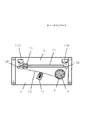
図1〜図4に示すように、内部に排気送風機1を設けた排気ユニット2の空気流路に連結し設けられる固定フード3と、固定フード3にスライド自在に設けられるスライドフード4と、このスライドフード4をスライド方向に駆動する駆動装置5とを備え、駆動装置5は、板材6に取付台7を介して正逆回転可能な駆動モータ8を設け、駆動モータ8には軸方向に上プーリ9aと下プーリ9bを2段組みとしたメインプーリ9を設け、スライドフード4の連結固定部10が直線方向に移動できるようにスライド溝11を板材6に設け、ワイヤー12の途中を連結固定部10に連結し、ワイヤー12の一端は、板材6に設けたスライド溝11の近傍に設けたサブプーリ13Aを介し、メインプーリ9の上プーリ9aに、時計方向に複数回巻回して連結し、ワイヤー12の他端は板材6に設けたスライド溝11の近傍に設けたサブプーリ13Bを介し、メインプーリ9の下プーリ9bに反時計方向に複数回巻回して連結し、ワイヤー12を介して連結固定部10がスライド溝11の両端部に移動したときに駆動モータ8の運転を停止する位置検知手段14A、14Bを設け、メインプーリ9とサブプーリ13A、13B間に張架されているワイヤー12のゆるみをなくすように調節するテンション部15を設け、以上のようなユニット化した構成で、固定フード3に装着されている。
(Embodiment 1)
As shown in FIGS. 1 to 4, a fixed hood 3 connected to an air flow path of an
上記構成において、固定フード3内にスライドフード4が収納されている状態においては、連結固定部10はサブプーリ13Bの近傍のスライド溝11の後端部にあって位置検知手段14Bにより、駆動モータ8の運転は停止状態にある。
In the above configuration, in a state where the
次に、スライドフード4を固定フード3の前方にスライドするときには、固定フード3に設けたスイッチ(図示せず)を操作することにより、駆動モータ8が反時計方向に回転され、駆動モータ8に設けたメインプーリ9の上プーリ9aにワイヤー12が巻き取られ、下プーリ9bに巻かれていたワイヤー12は巻き戻され、サブプーリ13Aを介してワイヤー12に連結した連結固定部10がスライド溝11をスライドして、連結固定部10に連結したスライドフード4が固定フード3前方側にスライドして移動し、連結固定部10がサブプーリ13A側のスライド溝の11の端部側にスライドすると、連結固定部10により位置検知手段14Aが作動して駆動モータ8の運転が停止され、スライドフード4は固定フード3の前方に引き出された状態で保持され、レンジフードとして運転ができることとなる。
Next, when the
また、レンジフードとしての運転を停止するためスライドフード4を固定フード3内に収納するときには、スイッチ(図示せず)を操作して駆動モータ8を駆動すると、メインプーリ9は、時計方向に回転し、下プーリ9bにワイヤー12が巻き取られ、上プーリ9aに巻回されていたワイヤー12は巻き戻され、スライドフード4に連結されている連結固定部10はサブプーリ13B側に向かいスライド溝11をスライドし、連結固定部10がサブプーリ13B近傍のスライド溝11の端部に近づくと連結固定部10が位置検知手段14Bを作動し、駆動モータ8の運転は停止され、スライドフード4は固定フード3内に収納した状態で保持される。
When the
このように本発明の実施の形態1の発明によれば、内部に排気送風機1を設けた排気ユニット2の空気流路に連通し設けられる固定フード3と、固定フード3にスライド自在に設けられるスライドフード4と、このスライドフード4をスライド方向に駆動する駆動装置とを備え、駆動装置5は、ワイヤー12を介しスライドフード4の連結固定部10を直線方向に移動する駆動モータ8と、駆動モータ8の運転を制御する位置検知手段14A、14Bとを一枚の板材6上に配設しユニット化したので、駆動モータ8と、駆動モータ8により駆動されるワイヤー12と、サブプーリ13Aと14Bを介して張架されるワイヤー12の駆動により直線方向に移動させるスライドフード4の連結固定部10と、連結固定部10が移動し、スライドフード4が所定の位置に移動したときに検知し、駆動モータ8の運転を停止する位置検知手段14A、14B等の多数の部材を一枚の板材6に配設してユニット化された駆動装置5が形成されることにより、駆動装置5を、スライドフード4をスライド自在に固定する固定フード3に設けることが容易となり、組立性が向上するとともに、駆動装置5の駆動モータ8やワイヤー12等が損傷し、新しい駆動装置5に取り替えたりメンテナンスを行なうときには、板材6を取り外し新しい駆動装置に5に交換したりメンテナンスを行なうことができることとなる。
As described above, according to the first embodiment of the present invention, the fixed hood 3 provided in communication with the air flow path of the
また、駆動モータ8に設けられるメインプーリ9を軸方向に上プーリ9aと下プーリ9bの2枚組みとしたことにより、ワイヤー12の一端はメインプーリ9の上プーリ9aに取り付け、ワイヤー12の他端はメインプーリ9の下プーリ9bに取り付けることができ、駆動モータ8により反時計方向にメインプーリ9が回動されるときには、上プーリ9aはワイヤー12を巻き取る方向に回動し、下プーリ9bはワイヤー12を巻き戻す方向に回動することにより、ワイヤー12が絡み合うことがなくなることとなる。
Further, since the main pulley 9 provided in the
(実施の形態2)
図5に示すように、駆動装置5Aをスライドフード4Aの左右に力を加えてスライドするように固定フード3Aの両側に設け構成する。
(Embodiment 2)
As shown in FIG. 5, the
上記構成において、スライドフード4Aをスライドするときには、駆動装置5Aを駆動すると、同一能力を持った駆動装置5Aにより、スライドフード4Aの左右に均等な力が加わり、スライドフード4Aはスライドされる。
In the above configuration, when sliding the slide hood 4A, when the
このように実施の形態2の発明によれば、駆動装置15Aをスライドフード4Aの左右を駆動するように固定フード3Aの両側に設けたので、同一能力の駆動装置5Aがスライドフード4Aの右側と左側の両面において駆動されるスライドフード4Aには左右同一のスライド駆動力が加わり、スライドフード4Aはこじれることなくスムーズにスライドすることができることとなる。
As described above, according to the second embodiment, the driving device 15A is provided on both sides of the fixed
(実施の形態3)
図6に示すように、駆動装置5Bをスライドフード4Bの左右の何れか一方を駆動するように固定フード3Bに設け、スライドフード4Bの他方側を駆動モータのない状態でサブプーリ13A、13B、13Cにより張架されるワイヤー12を設け、スライド溝11Aをスライドするスライドフード4Bの連結固定部10Aにワイヤー12Aを連結した従動装置17を設け構成する。
(Embodiment 3)
As shown in FIG. 6, the driving device 5B is provided on the fixed
上記構成において、スライドフード4Bをスライドするときに駆動装置5Bを駆動すると、スライドフード4Bの一方側がスライドするとともに、他方の従動装置17に設けた連結固定部10Aがスライド溝11Aをスライドするように従動して移動し、スライドフード4B全体がスライドされる。
In the above configuration, when the drive device 5B is driven when the
このように実施の形態3の発明によれば、駆動装置5Bをスライドフード4Bの左右の何れか一方を駆動するように固定フード3Bに設け、スライドフード4Bの他方側を駆動モータのない従動装置17を介して駆動するように設けたので、駆動装置5Bをスライドフード4Bの一方を駆動するように設け、他方を自由に移動するようにフリーな状態に設けた場合には、スライドフード4Bの他方側が勝手に前後に移動し、駆動装置5Bによるスライドフード4Bの移動とは異なる移動が生じ、スライドフード4Bのこじれにより、しゃくりや、がたつきが発生し、スライドフード4Bがスムーズにスライドしないこととなるが、他方側に駆動モータのない従動装置17を設けることにより、従動装置17が一定の抵抗となり、スライドフード4Bの他方側が勝手に前後に移動するということがなくなり、一方側に設けた駆動装置5Bと、他方側に設けた従動装置17により、スライドのバランスがとれ、スライドフード4Bがしゃくりやがたつくことなくスライドすることができることとなる。
As described above, according to the third embodiment, the drive device 5B is provided on the fixed
(実施の形態4)
図7に示すように、1本のワイヤー12Bと、このワイヤー12Bには、スライドフード4Cと連結固定される連結固定部10Bを設け、連結固定部10Bがスライドフード4Cのスライドに対し抵抗を与えるように、連結固定部10Bをスライド溝11Bにスライドさせる従動装置17Aを設け構成する。
(Embodiment 4)
As shown in FIG. 7, one
上記構成において、スライドフード4Cをスライドするときに、駆動装置5Bを駆動すると、スライドフード4Cの一方側がスライドするとともに、他方の従動装置17Aに設けた連結固定部10Bがスライド溝11Bをスライドするように従動して移動する。このときスライド溝11Bに対し、連結固定部10Bは一定の抵抗を受けてスライドすることとなり、スライドフード4C全体がスライドされる。
In the above configuration, when the drive device 5B is driven when the
このように実施の形態4の発明によれば、少なくとも一本のワイヤー12Bと、このワイヤー12Bにはスライドフード4Cと連結固定される連結固定部10Bを設け、連結固定部10Bがスライドフード4Cのスライドに対し抵抗を与えたので、駆動装置5Bを設けた一方側に対し、他方側には連結固定部10Bによる抵抗があることにより、スライドフード4Cの他方側が勝手に前後に移動することがなくなり、スライドフード4Cのスライド時にスライドフード4Cの他方側がしゃくりやがたつくことなく、スライドすることができることとなる。
As described above, according to the fourth embodiment, at least one
ユニット化した駆動装置や従動装置を用いることにより、物体を容易に駆動することができ、種々の駆動装置の用途にも適用できる。 By using a unitized drive device or driven device, an object can be easily driven and can be applied to various uses of the drive device.
1 排気送風機
2 排気ユニット
3 固定フード
3A 固定フード
3B 固定フード
4 スライドフード
4A スライドフード
4B スライドフード
4C スライドフード
5 駆動装置
5A 駆動装置
5B 駆動装置
6 板材
8 駆動モータ
9 メインプーリ
9a 上プーリ
9b 下プーリ
10 連結固定部
10B 連結固定部
12 ワイヤー
14A 位置検知手段
14B 位置検知手段
17 従動装置
17A 従動装置
DESCRIPTION OF
Claims (4)
Priority Applications (1)
| Application Number | Priority Date | Filing Date | Title |
|---|---|---|---|
| JP2005142654A JP4075908B2 (en) | 2005-05-16 | 2005-05-16 | Drive device for slide hood in range hood |
Applications Claiming Priority (1)
| Application Number | Priority Date | Filing Date | Title |
|---|---|---|---|
| JP2005142654A JP4075908B2 (en) | 2005-05-16 | 2005-05-16 | Drive device for slide hood in range hood |
Related Child Applications (1)
| Application Number | Title | Priority Date | Filing Date |
|---|---|---|---|
| JP2007159803A Division JP4730344B2 (en) | 2007-06-18 | 2007-06-18 | Drive device for slide hood in range hood |
Publications (3)
| Publication Number | Publication Date |
|---|---|
| JP2006317126A JP2006317126A (en) | 2006-11-24 |
| JP2006317126A5 JP2006317126A5 (en) | 2007-06-21 |
| JP4075908B2 true JP4075908B2 (en) | 2008-04-16 |
Family
ID=37537954
Family Applications (1)
| Application Number | Title | Priority Date | Filing Date |
|---|---|---|---|
| JP2005142654A Expired - Fee Related JP4075908B2 (en) | 2005-05-16 | 2005-05-16 | Drive device for slide hood in range hood |
Country Status (1)
| Country | Link |
|---|---|
| JP (1) | JP4075908B2 (en) |
Families Citing this family (4)
| Publication number | Priority date | Publication date | Assignee | Title |
|---|---|---|---|---|
| JP2008170034A (en) * | 2007-01-10 | 2008-07-24 | Hitachi Appliances Inc | Range hood |
| JP2008185291A (en) * | 2007-01-31 | 2008-08-14 | Hitachi Appliances Inc | Range hood |
| DE102013109707B4 (en) * | 2013-09-05 | 2016-04-07 | Miele & Cie. Kg | Traction device for a household appliance, household appliance and method |
| US11067293B1 (en) * | 2019-04-09 | 2021-07-20 | Alan Feiertag | Smoke director device configured to extend over a cooking surface of a cooking device |
-
2005
- 2005-05-16 JP JP2005142654A patent/JP4075908B2/en not_active Expired - Fee Related
Also Published As
| Publication number | Publication date |
|---|---|
| JP2006317126A (en) | 2006-11-24 |
Similar Documents
| Publication | Publication Date | Title |
|---|---|---|
| US7413000B2 (en) | Sun screen device | |
| US8020603B2 (en) | Blocking element, particularly for a gate used as a checkpoint | |
| JP4075908B2 (en) | Drive device for slide hood in range hood | |
| US7032349B2 (en) | Coreless motor door closure system for motor vehicles | |
| CA2425460A1 (en) | Device for operating a door leaf or the like and door structure provided with such a device | |
| JP4024738B2 (en) | Actuator | |
| CA2414555A1 (en) | Safety device for cord-operated control system | |
| US9538767B2 (en) | Door mechanism of a stock bin of bread maker | |
| JP4730344B2 (en) | Drive device for slide hood in range hood | |
| US20050003934A1 (en) | Resistance device for an exercise apparatus | |
| JP3162342U (en) | Unloader | |
| CN210107670U (en) | Air conditioner air outlet structure and air conditioner with same | |
| JP2006317126A5 (en) | ||
| DE50104836D1 (en) | CONTROL DEVICE | |
| KR100568065B1 (en) | Computer Desk with Monitor Entry and Exit | |
| US7652719B2 (en) | Electric dust-proof device | |
| CA2405712C (en) | Coreless motor door closure system | |
| JP5112657B2 (en) | Switch mounting structure | |
| US20060027338A1 (en) | Sealed window louver control mechanisms | |
| CN220453304U (en) | Pointing device | |
| CN214573544U (en) | Be applicable to bridge type octagon wing floodgate | |
| JP3118614U (en) | Fire hose winding device with an eccentric winding pin | |
| CN220402132U (en) | Cabinet and cabinet group | |
| JP6514137B2 (en) | Mobile front spoiler device | |
| JP2015125767A (en) | Mechanism for automatically opening door devices in time of power failure |
Legal Events
| Date | Code | Title | Description |
|---|---|---|---|
| A521 | Written amendment |
Free format text: JAPANESE INTERMEDIATE CODE: A523 Effective date: 20070507 |
|
| A621 | Written request for application examination |
Free format text: JAPANESE INTERMEDIATE CODE: A621 Effective date: 20070507 |
|
| A871 | Explanation of circumstances concerning accelerated examination |
Free format text: JAPANESE INTERMEDIATE CODE: A871 Effective date: 20070507 |
|
| RD01 | Notification of change of attorney |
Free format text: JAPANESE INTERMEDIATE CODE: A7421 Effective date: 20070613 |
|
| A975 | Report on accelerated examination |
Free format text: JAPANESE INTERMEDIATE CODE: A971005 Effective date: 20070727 |
|
| A131 | Notification of reasons for refusal |
Free format text: JAPANESE INTERMEDIATE CODE: A131 Effective date: 20070807 |
|
| A521 | Written amendment |
Free format text: JAPANESE INTERMEDIATE CODE: A523 Effective date: 20071004 |
|
| TRDD | Decision of grant or rejection written | ||
| A01 | Written decision to grant a patent or to grant a registration (utility model) |
Free format text: JAPANESE INTERMEDIATE CODE: A01 Effective date: 20080108 |
|
| A61 | First payment of annual fees (during grant procedure) |
Free format text: JAPANESE INTERMEDIATE CODE: A61 Effective date: 20080121 |
|
| FPAY | Renewal fee payment (event date is renewal date of database) |
Free format text: PAYMENT UNTIL: 20110208 Year of fee payment: 3 |
|
| FPAY | Renewal fee payment (event date is renewal date of database) |
Free format text: PAYMENT UNTIL: 20120208 Year of fee payment: 4 |
|
| FPAY | Renewal fee payment (event date is renewal date of database) |
Free format text: PAYMENT UNTIL: 20130208 Year of fee payment: 5 |
|
| FPAY | Renewal fee payment (event date is renewal date of database) |
Free format text: PAYMENT UNTIL: 20130208 Year of fee payment: 5 |
|
| FPAY | Renewal fee payment (event date is renewal date of database) |
Free format text: PAYMENT UNTIL: 20140208 Year of fee payment: 6 |
|
| LAPS | Cancellation because of no payment of annual fees |