JP4073625B2 - Method for equalizing temperature difference in molten glass and apparatus therefor - Google Patents
Method for equalizing temperature difference in molten glass and apparatus therefor Download PDFInfo
- Publication number
- JP4073625B2 JP4073625B2 JP2000531407A JP2000531407A JP4073625B2 JP 4073625 B2 JP4073625 B2 JP 4073625B2 JP 2000531407 A JP2000531407 A JP 2000531407A JP 2000531407 A JP2000531407 A JP 2000531407A JP 4073625 B2 JP4073625 B2 JP 4073625B2
- Authority
- JP
- Japan
- Prior art keywords
- temperature
- resistor heating
- heating elements
- flow path
- section
- Prior art date
- Legal status (The legal status is an assumption and is not a legal conclusion. Google has not performed a legal analysis and makes no representation as to the accuracy of the status listed.)
- Expired - Fee Related
Links
Images


Classifications
-
- C—CHEMISTRY; METALLURGY
- C03—GLASS; MINERAL OR SLAG WOOL
- C03B—MANUFACTURE, SHAPING, OR SUPPLEMENTARY PROCESSES
- C03B7/00—Distributors for the molten glass; Means for taking-off charges of molten glass; Producing the gob, e.g. controlling the gob shape, weight or delivery tact
- C03B7/02—Forehearths, i.e. feeder channels
- C03B7/06—Means for thermal conditioning or controlling the temperature of the glass
- C03B7/07—Electric means
-
- Y—GENERAL TAGGING OF NEW TECHNOLOGICAL DEVELOPMENTS; GENERAL TAGGING OF CROSS-SECTIONAL TECHNOLOGIES SPANNING OVER SEVERAL SECTIONS OF THE IPC; TECHNICAL SUBJECTS COVERED BY FORMER USPC CROSS-REFERENCE ART COLLECTIONS [XRACs] AND DIGESTS
- Y02—TECHNOLOGIES OR APPLICATIONS FOR MITIGATION OR ADAPTATION AGAINST CLIMATE CHANGE
- Y02P—CLIMATE CHANGE MITIGATION TECHNOLOGIES IN THE PRODUCTION OR PROCESSING OF GOODS
- Y02P40/00—Technologies relating to the processing of minerals
- Y02P40/50—Glass production, e.g. reusing waste heat during processing or shaping
- Y02P40/57—Improving the yield, e-g- reduction of reject rates
Landscapes
- Chemical & Material Sciences (AREA)
- Physics & Mathematics (AREA)
- Thermal Sciences (AREA)
- Engineering & Computer Science (AREA)
- Materials Engineering (AREA)
- Organic Chemistry (AREA)
- Glass Melting And Manufacturing (AREA)
- Control Of Resistance Heating (AREA)
- Re-Forming, After-Treatment, Cutting And Transporting Of Glass Products (AREA)
- Resistance Heating (AREA)
- Furnace Details (AREA)
- Waste-Gas Treatment And Other Accessory Devices For Furnaces (AREA)
Description
【0001】
本発明は、溶融ガラスが成形機の金型(mould)中に抜き出される抜き出し点(tap−off point)から上流にある溶融ガラス中の温度差を均等化する方法に関する。さらに、本発明は、均等化装置(equalizer)、すなわち、ガラス溶融物中の温度差を均等にする流路(channel)であって、抜き出し点においてその出口を有する前記流路に関する。
【0002】
ガラス瓶および別のタイプの容器のようなガラス製品の製造において、ガラス溶融物が所定の均一な重量および粘度を有することは最も重要である。もし重量および粘度が均一でないならばその収率は著しく低下する。これは、金型が十分に満たされないからであり、その結果としてガラス瓶は十分な壁の厚さを有しないし、また必要な強度を持たなくなる。
【0003】
ガラスはガラス用の炉で溶融され、そこから多くの移動流路を経由して液体状態で移動される。これらの移動流路において、ガラス溶融物の温度をできるだけ均一に保ちながら、所定のガラス温度に維持することが試みられた。各移動流路は、数メートルぐらいの典型的な長さを有する相対的に短い流路を含むいわゆる均等化装置に導かれる。均等化装置の目的は、ガラス溶融物を非常に均一な温度に保持することである。
【0004】
ガラスの粘度は温度に大いに依存する。その結果、移動流路における局部温度差は、特に均等化装置における局部温度差は、抜き出し点を離れるガラス溶融物の重量に対する製造された製品の重量として計算される製造収率に大いに影響する。
【0005】
従来の移動流路および均等化装置において、移動流路および均等化装置に沿って、加熱区分(heating zones)および冷却部分(cooling zones)を混在させて用いる。本発明は、まずガラスを適当な注入温度(casting temperature)に冷却し、ついでガラス溶融物中の温度を所定の注入温度に均等化して、均等化装置の縦方向に直角にとられたガラス溶融物の断面の至る所を均一にする。通常、冷却区分は、加熱が行われない区分である。そのかわりに、ガラス溶融物を自然に冷却することが可能である。通常、加熱区分にはガスバーナーを用いる加熱が組み込まれ、ここで、煙道ガスがガラス溶融物の露出された上面に沿って流れるが、また、抵抗体加熱要素(resistor heating elements)は流路の壁に沿って配置される。さらに、モリブデン電極は、それらの電極がガラス溶融物によって囲まれるような方法において流路中に挿入され、そして電流は2つの電極の間のガラス溶融物を通って流れる。
【0006】
従来の設備において、ガラス溶融物の温度は、ガラス溶融物の多くの別個の点において熱電対を使用して測定された。これらの測定値を用いて加熱装置を調節した。多くの別個の点において温度を測定し、これに基づいて加熱装置を調節することは、ガラス溶融物の外部境界面における局部の温度勾配がまだ存在している事実のために、十分でないことが経験された。
【0007】
本発明は、この問題を解決し、かつ従来技術によって提供されるよりもさらに有意なガラス溶融物における均一な温度を提供する方法および装置を含んでおり、これにより、収率の実質的な増加が提供される。
【0008】
それ故、本発明は、ガラス溶融物を移動させるように意図された流路の形態の少なくとも1つの温度均等化区分において溶融ガラス中の温度差を均等化する方法であって、前記区分は、溶融ガラスが成形機等の金型中に抜き出される抜き出し点から上流に位置しており、かつ抵抗体加熱要素が、温度均等化区分の壁、底および屋根に備えられており、抵抗体加熱要素によって接触されたそれぞれの壁、底および屋根の表面の温度が測定され、そして前記抵抗体加熱要素は、前記表面の温度がガラス溶融物の所定の抜き出し温度に等しくなるかまたは大部分等しくなるように、電気的制御器によって調節される、ことを特徴とする、前記均等化方法に関する。
【0009】
さらに、本発明は、特許請求の範囲の請求項に記載された一般的特徴を有するタイプの均等化装置に関する。
【0010】
以下に、本発明は、特に本発明の態様の例を示している添付図面と関連して、さらに詳細に説明される。
【0011】
第1図は、ガラス溶融物の移動に用いられる流路1の形態の溶融ガラス中の温度差を均等にするように意図された温度均等化区分の縦断面を示し、前記区分は、溶融ガラスが成形機等の金型(示されていない)中に抜き出される抜き出し点2から上流に位置している。流路1の断面は第3図に示した。流路は、酸化アルミニウムA1203のような適当なセラミック物質3から造られる。例えば、流路は、約1000mmの幅であり、そして約150mmの深さを有する。そのような断面寸法に関して、温度均等化区分は約2000mmの長さである。流路の上には、絶縁性耐火性物質、例えば耐火レンガから造られた屋根4が存在する。
【0012】
流路3の下には、例えば耐火レンガの形態の追加の絶縁体5が存在している。全温度均等化区分は、鋼梁(steel beam)6の形態の支持体上に静止している。また、屋根4の上には、例えば耐火レンガの形態の追加の絶縁体7、8が存在している。
【0013】
抜き出し点2を含んでいる抜き出し区分10にガラス溶融体11が入るのを防止するために、ストッパープラグ(stopper plug)9が備えられる。抜き出し区分は酸化アルミニウムのような適当なセラミック物質から造られている。
【0014】
本発明により、抵抗体加熱要素が、温度均等化区分の壁12、13、底14および屋根15に備えられている(第3図参照)。第3図において、数16〜19は、そのような抵抗体加熱要素を表している。これらは、特に、ハルシュタンマー(Hallstahammer)、スウェーデン(Sweden)にあるカンタール エイビー(KANTHAL AB)によって供給されている既知タイプの物である。
【0015】
本発明により、抵抗体加熱要素と接触している壁、底および屋根のそれぞれの表面の温度が測定され、そして前記抵抗体加熱要素16〜19は電気的制御装置によって調節されるので、前記表面の前記温度は、ガラス溶融体の所定の抜き出し温度に等しくまたは大部分等しく保たれる。
【0016】
測定は、従来の方法において熱電対20〜23を使用して実施される。熱電対20〜23は、抵抗体加熱要素から分離することができ、またあるいは、それらを抵抗体加熱要素と統合することもできる。
【0017】
温度均等化区分に沿って規則的な間隔をおいて配置された抵抗体加熱要素を持つことが好ましい。これは第1図に例示されており、この第1図において、底の要素24〜26および屋根の要素27〜29が、規則的な間隔をおいて配置されている。数30は、いくつかの熱電対を表している。
【0018】
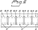
第2図には、平面図(horizontal view)で示された屋根および底の要素18、19の範囲(第3図参照)が例示されている。また、第2図には、サ−クル(circles)として側部の要素20、21(第3図参照)が示されている。これらは、均等化区分の縦方向において底の要素および屋根の要素と共に間隔をおいて配置されている。
【0019】
好ましい態様では、抵抗体加熱要素と接触している壁、底および屋根の表面の温度は、それぞれの抵抗体加熱要素の温度として測定される。
【0020】
ある1つの態様では、抵抗体加熱要素は、前記流路1を含むセラミック物質3の外面上のセラミック管の中に取り付けられたスパイラル要素である。この態様は、第2図においてサークル20、21によって例示される。
【0021】
他の態様では、抵抗体加熱要素は、前記流路1を含むセラミック物質3の外面に取り付けられているバンド形(band−shaped)抵抗体要素である。この態様は、第1図において要素24〜29によって例示されている。
【0022】
要素を公式化する方法は本発明に関して重要でない。重要なことは、ガラス溶融物の十分に高くかつ所定の温度を維持することができる十分に高い電力出力(power output)をもつ十分な数の要素を存在させなければならないことである。
【0023】
好ましい態様では、温度均等化区分は、前記流路の幅の少なくとも1〜2倍に相応する長さを持つようにする。
【0024】
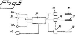
電気的制御器は前述した。第5図のブロック図にはそのような制御器が示されている。適当には、制御器には、連合したメモリーおよびソフトウェアと共にマイクロプロセッサー31が組み込まれている。すべての熱電対は適当な入力回路を経由してマイクロプロセッサーに連結されているので、その方法で、マイクロプロセッサーは、それぞれの熱電対によって測定された温度に相応するシグナルを得る。マイクロプロセッサーは、サイリスター(thyristor)、第5図において要素16、17、19として例示されたそれぞれのおよびすべての抵抗体加熱要素、を個々にまたはグループのいずれかで包含する調節回路32〜34を経由して調節するように設計される。
【0025】
要約すると、こうして、流路1を所定の温度に保つことができるように制御可能である多数の抵抗体加熱要素を包含する均等化区分が存在する。
【0026】
前述したように、抵抗体加熱要素によって接触されたそれぞれの壁、底および屋根の表面温度が測定され、そして抵抗体加熱要素は、前記表面温度がガラス溶融物の所定の抜き出し温度に等しくまたは大部分等しく保たれるように、電気的制御器で調節される。
【0027】
経験として、もし抵抗体加熱要素によって接触された壁がガラス溶融物の所定の温度であるならば、温度均等化区分における最初のウォーミングアップ時間後、流路を形成する材料3を通る温度勾配はゼロまたゼロに近い、ということが示された。これは、内部の流路の壁がガラス溶融物の所定の温度を想定させることを意味する。
【0028】
ガラス溶融物を温度均等化区分に移動するとき、所望の抜き出し温度に近いかまたは非常に近い平均温度を有しているが、その温度は、ガラス溶融物の移動方向に直角にとられたガラス溶融物の断面を通して不均質に分布している。これは、本明細書の導入部で述べた問題を生じる不均質な温度分布である。
【0029】
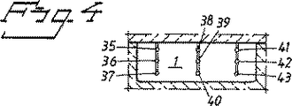
抜き出し点から上流に向かってすぐに、流路1中に位置するマトリックス44を形成する通常9個の熱電対35〜43が既知方法により配置され、そしてガラス溶融物中の温度分布を測定するのに用いられる。好ましくは、これらの熱電対44はマイクロプロセッサーに連結される。結果的に、温度分布が十分に均質でないときに警告シグナルを発するようにマイクロプロセッサーを配置することができる。
【0030】
従って、本発明により、本明細書の導入部に記載された問題は解決され、そして一方において、従来の温度均等化区分と比較して収率で10〜15%の増加が提供される。本発明の使用と従来方法との主な差異は、従来の温度均等化区分については、流路の内面の温度がガラス溶融物の所望温度より低いことである。
【0031】
以下に、実際に行った試験のいくつかの実施例を示した。
【0032】
温度均等化区分は2440mmの長さであった。流路は、1060mmの幅および152mmの深さであった。6個の底の要素および6個の屋根の要素を該区分に沿って規則的間隔をおいて配置した。各要素は、2855wの最大電力出力を有していた。6個の側部要素を該区分の2つの側部に沿って置き、規則的間隔をおいて配置した。これらの要素のそれぞれは、595wの最大電力出力を有していた。ガラス溶融物は、1秒につき10mmの速度で流路内を移動させた。
【0033】
本発明に従って該均等化区分に要素を装備する前に、前記マトリックス44中の温度を摂氏度(℃)で下記に表示した。下記の値は第4図に示された位置についてである。
【0034】

これにより、最大温度差は22℃であった。
【0036】
本発明を使用して始めた後、対応する温度は次のようであった。
【0037】
これらの数字に示されているように、最大温度差は3℃だけであった。
【0039】
態様のいくつかの実施例を前述した。しかし、要素の数、要素のタイプ、要素の電力出力および要素の位置は、当該の温度均等化区分に適応させなければならないことは明らかである。しかし、当業者には、存在しまたは最近製造された温度均等化区分において、本発明を実施するのに必要な電力出力および抵抗体加熱要素の数を計算するのに困難はないであろう。
【0040】
それ故、本発明は、前述された内容に限定されると考えるべきでない。それよりむしろ特許請求の範囲に記載された発明の範囲内において変えることができる。
【図面の簡単な説明】
【図1】 第1図は、本発明による温度均等化区分の一部分の縦方向にとった断面を示した図である。
【図2】 第2図は、温度均等化区分の上面の略図および抵抗体加熱要素の位置を示した図である。
【図3】 第3図は、温度均等化区分を通してとった図的断面を示した図である。
【図4】 第4図は、温度均等化区分の流路中の熱電対の位置を示した図である。
【図5】 第5図は、電気的制御装置の構成図を示した図である。[0001]
The present invention relates to a method for equalizing a temperature difference in molten glass upstream from a tap-off point at which molten glass is drawn into a mold of a molding machine. Furthermore, the present invention relates to an equalizer, i.e. a channel for equalizing the temperature difference in the glass melt, the channel having its outlet at the extraction point.
[0002]
In the manufacture of glass products such as glass bottles and other types of containers, it is most important that the glass melt has a predetermined uniform weight and viscosity. If the weight and viscosity are not uniform, the yield is significantly reduced. This is because the mold is not fully filled so that the glass bottle does not have sufficient wall thickness and does not have the required strength.
[0003]
The glass is melted in a glass furnace and is moved in a liquid state from there through a number of moving channels. In these moving channels, attempts have been made to maintain a predetermined glass temperature while keeping the temperature of the glass melt as uniform as possible. Each moving channel is led to a so-called equalization device comprising a relatively short channel having a typical length of the order of a few meters. The purpose of the equalizing device is to keep the glass melt at a very uniform temperature.
[0004]
Glass viscosity is highly temperature dependent. As a result, the local temperature difference in the moving channel, especially the local temperature difference in the equalization device, greatly affects the production yield calculated as the weight of the manufactured product relative to the weight of the glass melt leaving the extraction point.
[0005]
In the conventional moving flow path and the equalizing apparatus, heating zones and cooling zones are mixed and used along the moving flow path and the equalizing apparatus. The present invention first cools the glass to a suitable casting temperature, then equalizes the temperature in the glass melt to a predetermined pouring temperature, and takes the glass melt perpendicular to the longitudinal direction of the equalizing device. Uniform throughout the cross section of the object. Usually, the cooling section is a section where heating is not performed. Instead, it is possible to cool the glass melt naturally. Typically, the heating section incorporates heating using a gas burner, where flue gas flows along the exposed upper surface of the glass melt, but also the resistor heating elements are flow channels. Placed along the wall. In addition, the molybdenum electrodes are inserted into the flow path in such a way that they are surrounded by the glass melt, and current flows through the glass melt between the two electrodes.
[0006]
In conventional equipment, the temperature of the glass melt was measured using a thermocouple at many separate points of the glass melt. The heating device was adjusted using these measured values. Measuring the temperature at many separate points and adjusting the heating device based on this would not be sufficient due to the fact that local temperature gradients still exist at the external interface of the glass melt. Experienced.
[0007]
The present invention includes a method and apparatus that solves this problem and provides a more uniform temperature in the glass melt than that provided by the prior art, thereby substantially increasing the yield. Is provided.
[0008]
Therefore, the present invention is a method for equalizing a temperature difference in a molten glass in at least one temperature equalization section in the form of a channel intended to move the glass melt, said section comprising: Resistor heating, where the molten glass is located upstream from the extraction point where it is extracted into a mold such as a molding machine, and resistor heating elements are provided on the walls, bottom and roof of the temperature equalization section The temperature of each wall, bottom and roof surface contacted by the element is measured, and the resistor heating element is such that the surface temperature is equal to or largely equal to a predetermined extraction temperature of the glass melt The equalization method is characterized by being adjusted by an electrical controller.
[0009]
Furthermore, the invention relates to an equalizing device of the type having the general characteristics set forth in the claims.
[0010]
In the following, the invention will be described in more detail, in particular in connection with the accompanying drawings showing examples of aspects of the invention.
[0011]
FIG. 1 shows a longitudinal section of a temperature equalization section intended to equalize the temperature difference in the molten glass in the form of a channel 1 used for the movement of the glass melt, said section being a molten glass Is located upstream from the
[0012]
Below the
[0013]
In order to prevent the glass melt 11 from entering the extraction section 10 containing the
[0014]
In accordance with the invention, resistor heating elements are provided on the
[0015]
According to the present invention, the temperature of each surface of the wall, bottom and roof in contact with the resistor heating element is measured, and the resistor heating elements 16-19 are adjusted by an electrical controller so that the surface The temperature is kept equal to or largely equal to a predetermined extraction temperature of the glass melt.
[0016]
Measurements are performed using thermocouples 20-23 in a conventional manner. The thermocouples 20-23 can be separated from the resistor heating elements, or alternatively they can be integrated with the resistor heating elements.
[0017]
It is preferred to have resistor heating elements that are regularly spaced along the temperature equalization section. This is illustrated in FIG. 1, in which the bottom elements 24-26 and the roof elements 27-29 are arranged at regular intervals.
[0018]
FIG. 2 illustrates the range of roof and bottom elements 18, 19 (see FIG. 3) shown in a plan view (horizontal view). In FIG. 2,
[0019]
In a preferred embodiment, the temperature of the wall, bottom and roof surfaces in contact with the resistor heating element is measured as the temperature of the respective resistor heating element.
[0020]
In one embodiment, the resistor heating element is a spiral element mounted in a ceramic tube on the outer surface of the
[0021]
In another aspect, the resistor heating element is a band-shaped resistor element attached to the outer surface of the
[0022]
The method of formulating the elements is not important with respect to the present invention. What is important is that there must be a sufficient number of elements with a sufficiently high power output that can maintain a sufficiently high and predetermined temperature of the glass melt.
[0023]
In a preferred embodiment, the temperature equalization section has a length corresponding to at least 1 to 2 times the width of the flow path.
[0024]
The electrical controller has been described above. Such a controller is shown in the block diagram of FIG. Suitably, the controller incorporates a microprocessor 31 with associated memory and software. Since all thermocouples are connected to the microprocessor via a suitable input circuit, in that way, the microprocessor obtains a signal corresponding to the temperature measured by the respective thermocouple. The microprocessor includes thyristors, conditioning circuits 32-34 that include each and every resistor heating element, illustrated as
[0025]
In summary, there is thus an equalization section that includes a number of resistor heating elements that can be controlled to maintain the flow path 1 at a predetermined temperature.
[0026]
As described above, the surface temperature of each wall, bottom and roof contacted by the resistor heating element is measured, and the resistor heating element has a surface temperature equal to or greater than a predetermined extraction temperature of the glass melt. Adjusted with an electrical controller to keep it partly equal.
[0027]
As an experience, if the wall contacted by the resistor heating element is at the predetermined temperature of the glass melt, after the first warm-up time in the temperature equalization section, the temperature gradient through the
[0028]
When the glass melt is moved to the temperature equalization section, it has an average temperature close to or very close to the desired extraction temperature, but that temperature is taken perpendicular to the direction of movement of the glass melt. Heterogeneously distributed throughout the cross section of the melt. This is a heterogeneous temperature distribution that causes the problems described in the introductory part of this specification.
[0029]
Immediately upstream from the extraction point, typically nine thermocouples 35-43 forming a
[0030]
Thus, the present invention solves the problems described in the introductory part of the present specification and, on the other hand, provides a 10-15% increase in yield compared to conventional temperature equalization sections. The main difference between the use of the present invention and the conventional method is that for the conventional temperature equalization section, the temperature of the inner surface of the flow path is lower than the desired temperature of the glass melt.
[0031]
In the following, some examples of tests actually conducted are shown.
[0032]
The temperature equalization section was 2440 mm long. The flow path was 1060 mm wide and 152 mm deep. Six bottom elements and six roof elements were regularly spaced along the section. Each element had a maximum power output of 2855w. Six side elements were placed along the two sides of the section and arranged at regular intervals. Each of these elements had a maximum power output of 595 w. The glass melt was moved in the flow path at a speed of 10 mm per second.
[0033]
Prior to equipping the equalization section with elements according to the present invention, the temperature in the
[0034]
Thereby, the maximum temperature difference was 22 degreeC.
[0036]
After starting to use the present invention, the corresponding temperatures were as follows:
[0037]
As indicated by these numbers, the maximum temperature difference was only 3 ° C.
[0039]
Several examples of aspects have been described above. However, it is clear that the number of elements, the type of elements, the power output of the elements and the position of the elements must be adapted to the relevant temperature equalization section. However, those skilled in the art will have no difficulty calculating the number of power outputs and resistor heating elements required to implement the present invention in existing or recently manufactured temperature equalization sections.
[0040]
Therefore, the present invention should not be considered limited to what has been described above. Rather, variations can be made within the scope of the claimed invention.
[Brief description of the drawings]
FIG. 1 shows a longitudinal section of a portion of a temperature equalization section according to the present invention.
FIG. 2 is a schematic diagram of the top surface of the temperature equalization section and the position of the resistor heating element.
FIG. 3 is a diagram showing a schematic cross section taken through a temperature equalization section.
FIG. 4 is a diagram showing the position of the thermocouple in the flow path of the temperature equalization section.
FIG. 5 is a diagram showing a configuration diagram of an electrical control device.
Claims (11)
Applications Claiming Priority (3)
| Application Number | Priority Date | Filing Date | Title |
|---|---|---|---|
| SE9800397A SE511250C2 (en) | 1998-02-11 | 1998-02-11 | Method for equalizing temperature differences in liquid glass, and apparatus therefor |
| SE9800397-3 | 1998-02-11 | ||
| PCT/SE1999/000179 WO1999041206A1 (en) | 1998-02-11 | 1999-02-11 | Method for equalizing temperature differences in molten glass, and equipment therefor |
Publications (2)
| Publication Number | Publication Date |
|---|---|
| JP2003522085A JP2003522085A (en) | 2003-07-22 |
| JP4073625B2 true JP4073625B2 (en) | 2008-04-09 |
Family
ID=20410145
Family Applications (1)
| Application Number | Title | Priority Date | Filing Date |
|---|---|---|---|
| JP2000531407A Expired - Fee Related JP4073625B2 (en) | 1998-02-11 | 1999-02-11 | Method for equalizing temperature difference in molten glass and apparatus therefor |
Country Status (12)
| Country | Link |
|---|---|
| US (1) | US6799439B1 (en) |
| EP (1) | EP1053212B1 (en) |
| JP (1) | JP4073625B2 (en) |
| CN (1) | CN1241852C (en) |
| AU (1) | AU741493B2 (en) |
| BR (1) | BR9907978A (en) |
| CZ (1) | CZ300067B6 (en) |
| DE (1) | DE69924971T2 (en) |
| ES (1) | ES2243045T3 (en) |
| SE (1) | SE511250C2 (en) |
| TW (1) | TW520348B (en) |
| WO (1) | WO1999041206A1 (en) |
Families Citing this family (10)
| Publication number | Priority date | Publication date | Assignee | Title |
|---|---|---|---|---|
| DE10348072B4 (en) * | 2003-10-13 | 2006-01-05 | Schott Ag | Device for refining a glass melt |
| JP4313753B2 (en) * | 2004-11-24 | 2009-08-12 | Hoya株式会社 | Glass molded body, optical element manufacturing method, molten glass outflow apparatus, and glass molded body manufacturing apparatus |
| US8393177B2 (en) * | 2009-04-27 | 2013-03-12 | Corning Incorporated | Glass flow management by thermal conditioning |
| US8227055B2 (en) * | 2009-05-01 | 2012-07-24 | Guardian Industries Corp. | Vacuum insulating glass unit including infrared meltable glass frit, and/or method of making the same |
| US8408029B2 (en) * | 2009-11-17 | 2013-04-02 | Corning Incorporated | Method for thermally conditioning molten glass |
| KR101377543B1 (en) * | 2010-06-01 | 2014-03-26 | 주식회사 엘지화학 | Float bath for manufacturing glass and float glass forming method |
| TWI454435B (en) * | 2011-03-31 | 2014-10-01 | Avanstrate Inc | Glass plate manufacturing method |
| JP6011451B2 (en) * | 2013-05-14 | 2016-10-19 | 日本電気硝子株式会社 | Feeder |
| JP6498547B2 (en) * | 2015-06-30 | 2019-04-10 | AvanStrate株式会社 | Glass plate manufacturing method and glass plate manufacturing apparatus |
| CN114315102A (en) * | 2022-01-11 | 2022-04-12 | 四川航天拓鑫玄武岩实业有限公司 | Device and method for adjusting viscosity of basalt melt |
Family Cites Families (8)
| Publication number | Priority date | Publication date | Assignee | Title |
|---|---|---|---|---|
| US1603221A (en) * | 1924-01-25 | 1926-10-12 | Gen Electric | Method and apparatus for making glass |
| US2422734A (en) * | 1939-05-23 | 1947-06-24 | Jung Erwin Pierre | Device for regulating the temperature of electric furnaces of the resistance type |
| US3198619A (en) * | 1960-12-16 | 1965-08-03 | Owens Illinois Glass Co | Tubular forehearth for glass furnace |
| US3326655A (en) * | 1966-06-01 | 1967-06-20 | Harvey L Penberthy | Gob temperature control |
| US3585268A (en) * | 1968-01-04 | 1971-06-15 | Owens Illinois Inc | Metal-lined glass melter |
| DE3528332A1 (en) | 1985-08-07 | 1987-02-12 | Sorg Gmbh & Co Kg | Process for electrically heating glass-bearing channels, feeder channels and feeder heads of glass feeders, and equipment for carrying out the process |
| US4655812A (en) * | 1985-09-16 | 1987-04-07 | Emhart Industries, Inc. | Electric heating of glass forehearth |
| US4622059A (en) * | 1985-10-08 | 1986-11-11 | Emhart Industries, Inc. | Apparatus for controlling temperature within a forehearth |
-
1998
- 1998-02-11 SE SE9800397A patent/SE511250C2/en not_active IP Right Cessation
-
1999
- 1999-02-06 TW TW088101828A patent/TW520348B/en not_active IP Right Cessation
- 1999-02-11 CZ CZ20002574A patent/CZ300067B6/en not_active IP Right Cessation
- 1999-02-11 WO PCT/SE1999/000179 patent/WO1999041206A1/en active IP Right Grant
- 1999-02-11 BR BR9907978-0A patent/BR9907978A/en not_active IP Right Cessation
- 1999-02-11 ES ES99907988T patent/ES2243045T3/en not_active Expired - Lifetime
- 1999-02-11 EP EP99907988A patent/EP1053212B1/en not_active Expired - Lifetime
- 1999-02-11 JP JP2000531407A patent/JP4073625B2/en not_active Expired - Fee Related
- 1999-02-11 US US09/601,905 patent/US6799439B1/en not_active Expired - Fee Related
- 1999-02-11 AU AU27514/99A patent/AU741493B2/en not_active Ceased
- 1999-02-11 CN CNB998028320A patent/CN1241852C/en not_active Expired - Fee Related
- 1999-02-11 DE DE69924971T patent/DE69924971T2/en not_active Expired - Lifetime
Also Published As
| Publication number | Publication date |
|---|---|
| SE9800397L (en) | 1999-08-12 |
| DE69924971D1 (en) | 2005-06-02 |
| AU741493B2 (en) | 2001-11-29 |
| EP1053212B1 (en) | 2005-04-27 |
| CZ20002574A3 (en) | 2000-12-13 |
| EP1053212A1 (en) | 2000-11-22 |
| CN1290235A (en) | 2001-04-04 |
| US6799439B1 (en) | 2004-10-05 |
| ES2243045T3 (en) | 2005-11-16 |
| JP2003522085A (en) | 2003-07-22 |
| BR9907978A (en) | 2000-10-17 |
| TW520348B (en) | 2003-02-11 |
| WO1999041206A1 (en) | 1999-08-19 |
| CZ300067B6 (en) | 2009-01-21 |
| AU2751499A (en) | 1999-08-30 |
| SE511250C2 (en) | 1999-08-30 |
| DE69924971T2 (en) | 2006-04-27 |
| SE9800397D0 (en) | 1998-02-11 |
| CN1241852C (en) | 2006-02-15 |
Similar Documents
| Publication | Publication Date | Title |
|---|---|---|
| JP4073625B2 (en) | Method for equalizing temperature difference in molten glass and apparatus therefor | |
| US4738706A (en) | Method and device for the thermal regulation of a moving fluid mass | |
| JP4563391B2 (en) | Apparatus and method for manufacturing tubes or rods | |
| US3164457A (en) | Fiber producing bushing | |
| JP3672942B2 (en) | Apparatus for extraction by pouring at a controlled flow rate of material melted in a melting furnace with cooling walls | |
| CA1237460A (en) | Electrically heated forehearth and method of controlling molten glass temperature therein | |
| US3294517A (en) | Forehearth construction | |
| CN109264966A (en) | A method of preventing platinum channel agitator upper flange deformation | |
| KR20200111775A (en) | Convection pattern estimation method of silicon melt, oxygen concentration estimation method of silicon single crystal, silicon single crystal manufacturing method, and silicon single crystal pulling device | |
| CN108291779A (en) | Measure the electrode length in melting furnace | |
| US4052186A (en) | Method and apparatus for conditioning molten glass | |
| FI59578C (en) | FOER CONDITIONING CONDITIONING AVAILABILITY IN GLASMASS OCH EN GLASSMAELTNINGSUGN | |
| US4070148A (en) | Apparatus for monitoring product temperature in an open ended, secondary emission, product carrying conveyor furnace | |
| JPS60251136A (en) | Method for forming rodlike glass | |
| CN116601121A (en) | Glass melting furnace monitoring method and glass article manufacturing method | |
| US3880634A (en) | Method and apparatus for producing tubing from short glasses | |
| KR101853974B1 (en) | Method for Controlling Stress in a Heated Refractory Ceramic Body | |
| JPH0531505B2 (en) | ||
| JP2633534B2 (en) | Method and apparatus for temperature control of flowing fluid | |
| JP2001158625A (en) | Device and method for controlling melted glass flow passing through front oven | |
| JPH03108634A (en) | Electric furnace for glass strain point testing apparatus | |
| CA1203827A (en) | Electric boosting control for a glass forehearth | |
| JP2024060295A (en) | Glass article manufacturing method and manufacturing device | |
| JPH0116031Y2 (en) | ||
| RU2020036C1 (en) | Device for determining level of melt in heat apparatus |
Legal Events
| Date | Code | Title | Description |
|---|---|---|---|
| A711 | Notification of change in applicant |
Free format text: JAPANESE INTERMEDIATE CODE: A711 Effective date: 20050606 |
|
| A711 | Notification of change in applicant |
Free format text: JAPANESE INTERMEDIATE CODE: A711 Effective date: 20050512 |
|
| A711 | Notification of change in applicant |
Free format text: JAPANESE INTERMEDIATE CODE: A711 Effective date: 20050926 |
|
| RD02 | Notification of acceptance of power of attorney |
Free format text: JAPANESE INTERMEDIATE CODE: A7422 Effective date: 20051013 |
|
| RD04 | Notification of resignation of power of attorney |
Free format text: JAPANESE INTERMEDIATE CODE: A7424 Effective date: 20051013 |
|
| A521 | Written amendment |
Free format text: JAPANESE INTERMEDIATE CODE: A523 Effective date: 20051201 |
|
| A131 | Notification of reasons for refusal |
Free format text: JAPANESE INTERMEDIATE CODE: A131 Effective date: 20070608 |
|
| A521 | Written amendment |
Free format text: JAPANESE INTERMEDIATE CODE: A523 Effective date: 20070905 |
|
| A521 | Written amendment |
Free format text: JAPANESE INTERMEDIATE CODE: A821 Effective date: 20070905 |
|
| A131 | Notification of reasons for refusal |
Free format text: JAPANESE INTERMEDIATE CODE: A131 Effective date: 20071106 |
|
| A521 | Written amendment |
Free format text: JAPANESE INTERMEDIATE CODE: A523 Effective date: 20071115 |
|
| A521 | Written amendment |
Free format text: JAPANESE INTERMEDIATE CODE: A821 Effective date: 20071115 |
|
| TRDD | Decision of grant or rejection written | ||
| A01 | Written decision to grant a patent or to grant a registration (utility model) |
Free format text: JAPANESE INTERMEDIATE CODE: A01 Effective date: 20080118 |
|
| A61 | First payment of annual fees (during grant procedure) |
Free format text: JAPANESE INTERMEDIATE CODE: A61 Effective date: 20080123 |
|
| FPAY | Renewal fee payment (event date is renewal date of database) |
Free format text: PAYMENT UNTIL: 20110201 Year of fee payment: 3 |
|
| R150 | Certificate of patent or registration of utility model |
Free format text: JAPANESE INTERMEDIATE CODE: R150 |
|
| LAPS | Cancellation because of no payment of annual fees |