JP4073514B2 - Liquid crystal display - Google Patents
Liquid crystal display Download PDFInfo
- Publication number
- JP4073514B2 JP4073514B2 JP04332897A JP4332897A JP4073514B2 JP 4073514 B2 JP4073514 B2 JP 4073514B2 JP 04332897 A JP04332897 A JP 04332897A JP 4332897 A JP4332897 A JP 4332897A JP 4073514 B2 JP4073514 B2 JP 4073514B2
- Authority
- JP
- Japan
- Prior art keywords
- liquid crystal
- pixels
- display
- state
- crystal display
- Prior art date
- Legal status (The legal status is an assumption and is not a legal conclusion. Google has not performed a legal analysis and makes no representation as to the accuracy of the status listed.)
- Expired - Fee Related
Links
Images


Classifications
-
- G—PHYSICS
- G02—OPTICS
- G02F—OPTICAL DEVICES OR ARRANGEMENTS FOR THE CONTROL OF LIGHT BY MODIFICATION OF THE OPTICAL PROPERTIES OF THE MEDIA OF THE ELEMENTS INVOLVED THEREIN; NON-LINEAR OPTICS; FREQUENCY-CHANGING OF LIGHT; OPTICAL LOGIC ELEMENTS; OPTICAL ANALOGUE/DIGITAL CONVERTERS
- G02F1/00—Devices or arrangements for the control of the intensity, colour, phase, polarisation or direction of light arriving from an independent light source, e.g. switching, gating or modulating; Non-linear optics
- G02F1/01—Devices or arrangements for the control of the intensity, colour, phase, polarisation or direction of light arriving from an independent light source, e.g. switching, gating or modulating; Non-linear optics for the control of the intensity, phase, polarisation or colour
- G02F1/13—Devices or arrangements for the control of the intensity, colour, phase, polarisation or direction of light arriving from an independent light source, e.g. switching, gating or modulating; Non-linear optics for the control of the intensity, phase, polarisation or colour based on liquid crystals, e.g. single liquid crystal display cells
- G02F1/133—Constructional arrangements; Operation of liquid crystal cells; Circuit arrangements
-
- G—PHYSICS
- G09—EDUCATION; CRYPTOGRAPHY; DISPLAY; ADVERTISING; SEALS
- G09G—ARRANGEMENTS OR CIRCUITS FOR CONTROL OF INDICATING DEVICES USING STATIC MEANS TO PRESENT VARIABLE INFORMATION
- G09G3/00—Control arrangements or circuits, of interest only in connection with visual indicators other than cathode-ray tubes
- G09G3/20—Control arrangements or circuits, of interest only in connection with visual indicators other than cathode-ray tubes for presentation of an assembly of a number of characters, e.g. a page, by composing the assembly by combination of individual elements arranged in a matrix no fixed position being assigned to or needed to be assigned to the individual characters or partial characters
- G09G3/34—Control arrangements or circuits, of interest only in connection with visual indicators other than cathode-ray tubes for presentation of an assembly of a number of characters, e.g. a page, by composing the assembly by combination of individual elements arranged in a matrix no fixed position being assigned to or needed to be assigned to the individual characters or partial characters by control of light from an independent source
- G09G3/36—Control arrangements or circuits, of interest only in connection with visual indicators other than cathode-ray tubes for presentation of an assembly of a number of characters, e.g. a page, by composing the assembly by combination of individual elements arranged in a matrix no fixed position being assigned to or needed to be assigned to the individual characters or partial characters by control of light from an independent source using liquid crystals
- G09G3/3611—Control of matrices with row and column drivers
- G09G3/3622—Control of matrices with row and column drivers using a passive matrix
- G09G3/3629—Control of matrices with row and column drivers using a passive matrix using liquid crystals having memory effects, e.g. ferroelectric liquid crystals
- G09G3/3633—Control of matrices with row and column drivers using a passive matrix using liquid crystals having memory effects, e.g. ferroelectric liquid crystals with transmission/voltage characteristic comprising multiple loops, e.g. antiferroelectric liquid crystals
-
- G—PHYSICS
- G09—EDUCATION; CRYPTOGRAPHY; DISPLAY; ADVERTISING; SEALS
- G09G—ARRANGEMENTS OR CIRCUITS FOR CONTROL OF INDICATING DEVICES USING STATIC MEANS TO PRESENT VARIABLE INFORMATION
- G09G2320/00—Control of display operating conditions
- G09G2320/02—Improving the quality of display appearance
- G09G2320/0257—Reduction of after-image effects
-
- G—PHYSICS
- G09—EDUCATION; CRYPTOGRAPHY; DISPLAY; ADVERTISING; SEALS
- G09G—ARRANGEMENTS OR CIRCUITS FOR CONTROL OF INDICATING DEVICES USING STATIC MEANS TO PRESENT VARIABLE INFORMATION
- G09G2330/00—Aspects of power supply; Aspects of display protection and defect management
- G09G2330/04—Display protection
Description
【0001】
【発明の属する技術分野】
本発明はスメクチック相を示す液晶を液晶層とし、マトリックス状の画素を有する液晶表示パネルや液晶光シャッターアレイ等の液晶表示ディスプレイに関するものである。
【0002】
【従来の技術】
スメクチック相を示す液晶としては、強誘電性液晶や反強誘電性液晶が一般に知られている。どちらの液晶も自発分極を有し、外部からの電界や磁界の影響を受け、自発分極の向きが変更されることによって、表示用ディスプレイとして応用されている。例えば反強誘電性液晶を用いた液晶パネルは、日本電装(株)及び昭和シェル石油(株)らの特開平2ー173724号公報で広視野角を有すること、高速応答が可能なこと、マルチプレックス特性が良好なこと等が報告されて以来、精力的に研究がなされている。
【0003】
図2は反強誘電性液晶をディスプレイとして用いる場合の偏光板配置を示す液晶セル構成図である。クロスニコルに合わせた偏光板21a、bの間に、どちらかの偏光板の偏光軸と電圧無印加時に於ける平均的な分子の長軸方向がほぼ平行になるように液晶セル22を置き、電圧無印加時に黒が、電界印加時には白が表示できるようにしている。このようなセル構成の液晶セルに電圧を印加したとき、それに対する透過率変化をグラフにプロットすると図3のようなループを描くことが出来る。電圧を印加し増加させていく場合に透過率が変化し始める電圧値をV1、透過率の変化が飽和する電圧値をV2、逆に電圧値を減少させていく場合に透過率が減少し始める電圧値をV5、また逆極性の電圧を印加し、その絶対値を増加させた場合に透過率が変化し始める電圧値をV3、透過率変化が飽和する電圧値をV4、逆に電圧の絶対値を減少させた場合に透過率が変化し始める電圧値をV6とする。この図3からは電圧値が反強誘電性液晶分子の閾値以上をとる場合に第1の強誘電性状態が選択され、また印加電圧の極性の違いによって、第2の強誘電性状態が選択され、これらの強誘電性状態から、電圧値がある閾値より低い場合には反強誘電性状態が選択されることがわかる。
【0004】
これに対して、強誘電性液晶は反強誘電性液晶と電圧−透過率特性が異なり、単一のヒステリシスカーブを示し、図3のようなダブルヒステリシスカーブは示さない。一般に強誘電性液晶をディスプレイに用いる場合には強誘電性状態にある分子の長軸方向に、いずれかの偏光板の偏光軸を合わせ、ある電圧以上の電圧を印加すると黒が、また逆極性のある電圧を印加すると白が表示されるように設定される。
【0005】
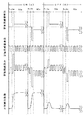
次に反強誘電性液晶を用いた一般的な駆動方法について説明する。図4に走査電極と信号電極のを基板上に配置した図を示す。走査電極をそれぞれX1、X2、Xn等と示し、信号電極はY1、Y2、Ym等と示し、それぞれが交差する斜線部分が画素(A11、Anm)である。画素への書き込み、は図5に示すように、走査電極と信号電極に電圧を印加し、その合成電圧波形が画素(Anm)に印加され行われる。選択期間(Se)で第1、もしくは第2の強誘電性状態、もしくは反強誘電性状態を選択し、その状態を次の非選択期間(NSe)で保持させている。つまり選択期間(Se)で印加したセレクトパルスによる透過光量をその後の非選択期間(NSe)で保持させることにより表示を行っている。
【0006】
また選択期間に印加されるセレクトパルスの直前で、反強誘電性液晶の分子状態が異なると、画素の透過光量を正確な所定の値にする事が難しく、そのためセレクトパルスを印加する前に、その画素の表示以前の状態に関わらず常に反強誘電性状態にリセットすることが良く行われてきた。この反強誘電性状態にリセットする方法としては、リセット期間内の電圧値を0Vにし、反強誘電性液晶自身の持つ粘性や弾性などの特性による自然緩和によって反強誘電性状態にリセットする方法や、適当な印加電圧を印加して反強誘電性状態にリセットする方法等がある。
【0007】
【発明が解決しようとする課題】
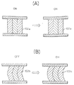
しかしながら反強誘電性液晶ディスプレイで静止画などの同じ表示を長時間行ったあとに他の表示を行った場合に、以前に表示していた表示画面が見えてしまう現象(以後焼き付き現象と呼ぶ)が起きた。この現象を図6を用いて説明する。この焼き付き現象は反強誘電性液晶が層構造を持つことに起因していると考えられている。例えば長時間強誘電状態で白表示(図6(A)ON・・・ブックシェルフ構造)であった画素と、長時間反強誘電状態で黒表示(図6(B)OFF・・・シェブロン構造)であった画素では、次に白表示(ON)にすると、前者は図6(A)のように、層構造102aの形状は変わらないが、後者では図6(B)の白表示(ON)のように、同じ白表示(ON)であっても、層構造102aと102bのように違いが生じ、これがその後同様の層構造に戻るために時間がかかることが原因と考えられている。
【0008】
また、強誘電性液晶を用いた強誘電性液晶ディスプレイでも静止画などの同じ表示を長時間行った後に、同様の焼き付き現象が起きることが知られている。この原因は反強誘電性液晶のそれとは異なり、液晶セル内に存在する不純物イオンの移動によるものと考えられている。強誘電性液晶は自発分極を有しており、外部電圧が0Vの場合には、自発分極による内部電界が常に液晶セルに対して垂直方向に存在する。この内部電界を打ち消すように液晶セル内の不純物イオンがセル基板界面に移動し、そして不純物イオンによるイオン電界が自発分極が作る内部電界と逆方向に発生する。さらにこの状態が長時間続くと、不純物イオンがセル基板界面に吸着されるため、自発分極による内部電界が消えた後も、このイオン電界が存在し続けることになり、これが焼き付き現象の原因と推察されている。
【0009】
そこで本発明ではこれらの問題点を解決し、つまり反強誘電性液晶を用いた液晶ディスプレイでは、連続駆動による層構造の変化を補正し、層構造の違いから起きる焼き付け現象を低減し、また強誘電性液晶を用いた液晶ディスプレイでは、同一方向の自発分極による内部電界を長時間存在させないようにし、同様に焼き付き現象を低減し、高コントラストな表示を行うことが可能な液晶ディスプレイを提供することを目的としている。
【0010】
【課題を解決するための手段】
上記目的を達成するために本発明では、以下の手段を用いた。
【0011】
一対の基板間にスメクチック相を示す液晶を挟持し、複数の画素を有する液晶ディスプレイにおいて、画素への一回の書き込みが、少なくとも一つの走査期間において行われ、走査期間は画素の透過光量を決定するための電圧が印加される選択期間と、選択期間で決定した透過光量を保持する非選択期間とを有し、複数の画素の中から、任意または無作為に画素を抽出し、抽出された該画素について、表示データに関わらず、非選択期間中では強制的に、ブックシェルフ層構造になるような表示状態、または同一方向の自発分極による内部電界を長時間存在させないようにするために白表示状態とすることを特徴とする。
【0012】
また、抽出された画素の数を、抽出する毎に設定する機能を備えたことを特徴とする。
【0013】
また、画素を抽出して、強制的に表示状態または白表示状態とする周期を変更する機能を備えたことを特徴とする。
【0014】
また、一対の基板間には、走査電極と信号電極とを備え、強制的に表示状態または白表示状態とするために、画素に対応する信号電極に印加する信号電極波形を表示状態または白表示状態とする電圧波形に変えることを特徴とする。
【0015】
また、表示データを発生する表示データ発生回路と、表示データを表示状態または白表示状態とする変換機能を有する表示データ変換回路とを有し、抽出された画素は、表示データ変換回路で変換された表示データを表示することを特徴とする。
【0016】
また、表示データ変換回路は、任意または無作為に画素を抽出する機能を有することを特徴とする。また、表示データ変換回路は、画素を抽出して、表示状態または前記白表示状態とする周期を任意に設定する機能を有することを特徴としている。
【0017】
あるいは表示データ変換回路は、抽出された画素の数を任意に設定する機能を備えていることを特徴としている。
【0018】
あるいは画素を抽出して、前記表示状態または前記白表示状態とする周期を全画素を1回書きこむ1周期と等しくすることを特徴としている。
【0019】
ここでスメクチック相を示す液晶としては、強誘電性液晶または反強誘電性液晶が一般的にあげられる。
【0020】
【発明の実施の形態】
先に記述した通り、例えば反強誘電性液晶では電圧無印加の状態において図6(B)OFFのように層が折れた状態(以後シェブロン構造と呼ぶ。)になっており、一定の電圧が印加した場合には、図6(A)ONに示すように基板に対してほぼ垂直に立った状態(以後ブックシェルフ構造と呼ぶ。)になる。上記課題を解決する手段の項で記載した所定の表示状態とは、このブックシェルフ構造になるような表示状態にする事が望ましい。
【0021】
また走査電極を有する液晶ディスプレイにおいては、表示データ発生回路は1本の走査電極上の画素数(信号電極の数)に対応した信号が出力される。この信号が表示データ変換回路に入力されると、特定の画素に対応した信号だけが所定の表示状態に変換されて出力される。またこの特定の画素は任意に設定できるか、無作為に設定されることが望ましい。
【0022】
また、表示データを変換する画素の位置を走査電極の1行毎に変更するか、もしくは2行毎、あるいはn行毎に変更するかを任意に設定する機能を有するか、または自動的に変更する機能を有することが望ましい。
【0023】
このように本発明を用いて反強誘電性液晶ディスプレイで表示を行った場合には、常に黒表示しか行わない画素(層構造がシェブロン構造)と、白表示しか行わない画素(層構造がブックシェルフ構造)でも、表示状態が強制的にある期間、液晶の層構造がブックシェルフ構造へ強制的に変更され、実際には層構造の違いが起こりにくく、焼き付き現象が低減する。
【0024】
また本発明を用いて強誘電性液晶ディスプレイで表示を行った場合には、本発明で表示を行うことにより、同一方向の自発分極による内部電界を長時間存在させないようにすることが可能となり、同様に焼き付き現象を低減することができる。
【0025】
本発明の液晶ディスプレイでは、1画面内の必ずどこかの画素が、表示データとは異なった表示状態を実行することになるが、本発明の表示データ変換回路では表示書き換え画素を無作為に設定でき、また書き換え周期も変更できるので、常に異なる画素が書き換えられ、またその書き換えられる画素が、時間の経過と共に箇所が変化するため、この表示データが変換された画素を人間の目視観察でははっきりと認識することはできず、表示の見栄えが劣化することがほとんどない。また表示データを強制的に変更する画素の数や変更周期などを任意に変更することにより、たとえば動画や静止画を表示させても表示品位に影響がない様に最適化することができる。
【0026】
【実施例】
以下本発明の実施例を図面に基づいて詳細に説明する。図7は本実施例に用いた液晶パネル構成図である。本実施例で用いた液晶パネルは約2μの厚さの反強誘電性液晶層62を持つ一対のガラス基板63a、63bと2枚のガラスを張り合わせるためのシール材66から構成されている。ガラス基板の対向面には電極64a、64bが形成されており、その上に高分子配向膜65a、65bが塗布され、ラビング処理がなされている。さらに一方のガラス基板の外側に偏光板の偏光軸とラビング軸とが平行になるように第1の偏光板61aが設置されており、他方のガラス基板の外側には第1の偏光板61aの偏光軸と90°異なるようにして第2の偏光板61bが設置されている。
【0027】
また走査電極と信号電極は先に示した図4のように配置した。走査電極は240本、信号電極は320本とした。それぞれが交差する斜線部分が画素(A11、Anm)である。
【0028】
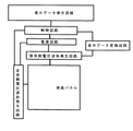
図1は本発明の表示回路のブロック図である。表示データ発生回路と信号側電圧波形発生回路の間に表示データ変更回路が構成されている。一走査期間は約17msとし、表示データ変換回路では表示周期(約35μs)と同じ周期で表示データを強制的に白表示(ブックシェルフ層構造)に変更させている。一周期に変更する画素の数は10画素とし、変更周期で変更される画素は無作為に抽出するように設定されているために、平均約544msで全ての画素が必ず1度は表示データに関わらずに白表示(ブックシェルフ層構造)になった。
【0029】
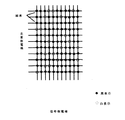
図8は全画素を黒表示になるように表示したときの、ある時間での画素の状態を示した液晶ディスプレイ画面の一部の図である。ディスプレイ全体で約7万7千画素あり、この中の2400画素が実際の表示データとは異なる白表示となったが、実際とは異なる白表示を行った画素が平均的に分散しているので目視観察では表示品位が下がることはなく、焼き付き現象も生じなかった。
【0030】
また静止画の多い場合には、あらかじめ焼き付きが強く起こりそうな画素を特定したり、表示データを変更する周期を任意の値に設定したり、全画素を一回書き込む一周期に強制的に変更する画素の数を増やすことにより、よりよい結果が得られた。反対に動画が多い画面を表示するときは、表示データを変更する画素を無作為に設定したり、変更する周期を自動的に更新したり、全画素を一回書き込む一周期あたりに強制的に変更する画素の数を減らす、あるいは数を自動的に変更することによって、よりよい結果が得られた。
【0031】
次に液晶パネル内に、強誘電性液晶を封入して強誘電性液晶ディスプレイを作製し、同様の表示動作を行った。やはり無作為に抽出した画素で、表示データとは異なる白表示を行うことにより、全ての画素が必ず1度は表示データに関わらずに白表示を行った。よって、すべての画素において同一方向の自発分極による内部電界を長時間存在させないようにすることができ、同様に焼き付き現象を低減することができた。
【0032】
また、走査電極と信号電極を用いた時分割駆動の代わりに、各画素を直接駆動できるアクティブマトリクス駆動を用いた場合でも、まったく同様の効果が得られた。
【0033】
【発明の効果】
以上の実施例で述べたように、本発明を用いて表示を行うことにより、常に表示画素による層構造の違いをなくす、あるいは自発分極による内部電界の発生を短時間にすることができ、焼き付け現象を低減し、かつ表示品位が落ちることなく良好な表示を行うことができる。
【図面の簡単な説明】
【図1】本発明の実施例の回路ブロック図である。
【図2】本発明の反強誘電性液晶セルと偏光板の構成図である。
【図3】本発明の反強誘電性液晶表示素子のヒステリシスカーブを表す図である。
【図4】本発明で用いた電極のマトリックス構造を示す図である。
【図5】従来の駆動方法を示す図である。
【図6】本発明の反強誘電性液晶の層構造を示す図である。
【図7】本発明で用いた液晶パネルの構成図の構成図である。
【図8】本実施例の黒表示を行った図である。
【符号の説明】
OFF(B) 黒表示
ON(W) 白表示
Rs リセット期間
Se 選択期間
NSe 非選択期間
X1〜Xn 走査電極
Y1〜Ym 信号電極
Anm 画素
T 透過光量
21a、21b 偏光板
22 液晶セル
61a、61b 偏光板
62a、62b 反強誘電性液晶液晶
63a、63b ガラス基板
64a、64b 電極
65a、65b 配向膜
66 シール材
102a、102b 層構造[0001]
BACKGROUND OF THE INVENTION
The present invention relates to a liquid crystal display such as a liquid crystal display panel or a liquid crystal optical shutter array having a liquid crystal layer as a liquid crystal layer and having matrix-like pixels.
[0002]
[Prior art]
Ferroelectric liquid crystals and antiferroelectric liquid crystals are generally known as liquid crystals exhibiting a smectic phase. Both liquid crystals have spontaneous polarization and are applied as display devices by changing the direction of spontaneous polarization under the influence of an external electric field or magnetic field. For example, a liquid crystal panel using an antiferroelectric liquid crystal has a wide viewing angle, a high-speed response, and a multi-display in JP-A-2-173724 by Nippon Denso Co., Ltd. and Showa Shell Sekiyu Co., Ltd. Since the report of good plex characteristics, etc., research has been conducted energetically.
[0003]
FIG. 2 is a configuration diagram of a liquid crystal cell showing the arrangement of polarizing plates when an antiferroelectric liquid crystal is used as a display. Between the polarizing plates 21a and 21b matched to crossed Nicols, the
[0004]
On the other hand, the ferroelectric liquid crystal is different from the anti-ferroelectric liquid crystal in voltage-transmittance characteristics, shows a single hysteresis curve, and does not show a double hysteresis curve as shown in FIG. In general, when using a ferroelectric liquid crystal for a display, align the polarization axis of one of the polarizing plates with the long axis direction of the molecule in the ferroelectric state, and apply a voltage higher than a certain voltage, and black or reverse polarity. When a certain voltage is applied, white is displayed.
[0005]
Next, a general driving method using an antiferroelectric liquid crystal will be described. FIG. 4 shows a diagram in which scan electrodes and signal electrodes are arranged on a substrate. The scanning electrodes are indicated as X1, X2, Xn, etc., the signal electrodes are indicated as Y1, Y2, Ym, etc., and the hatched portion where each intersects is a pixel (A11, Anm). As shown in FIG. 5, writing to the pixel is performed by applying a voltage to the scan electrode and the signal electrode, and applying the combined voltage waveform to the pixel (Anm). The first or second ferroelectric state or antiferroelectric state is selected in the selection period (Se), and the state is held in the next non-selection period (NSe). That is, the display is performed by holding the transmitted light amount by the select pulse applied in the selection period (Se) in the subsequent non-selection period (NSe).
[0006]
Also, if the molecular state of the antiferroelectric liquid crystal is different just before the select pulse applied in the selection period, it is difficult to set the transmitted light amount of the pixel to an accurate predetermined value, so before applying the select pulse, Regardless of the state before the display of the pixel, it has often been well reset to the antiferroelectric state. As a method of resetting to the antiferroelectric state, the voltage value in the reset period is set to 0 V, and the antiferroelectric liquid crystal itself is reset to the antiferroelectric state by natural relaxation due to characteristics such as viscosity and elasticity. And a method of resetting the antiferroelectric state by applying an appropriate applied voltage.
[0007]
[Problems to be solved by the invention]
However, when the same display such as a still image is displayed on an antiferroelectric liquid crystal display for a long time and then another display is performed, the previously displayed display screen can be seen (hereinafter referred to as a burn-in phenomenon). Happened. This phenomenon will be described with reference to FIG. This image sticking phenomenon is considered to be caused by the antiferroelectric liquid crystal having a layer structure. For example, a pixel that has been white in a ferroelectric state for a long time (FIG. 6 (A) ON: bookshelf structure) and a pixel that has been displayed for a long time in an antiferroelectric state (FIG. 6 (B) OFF: a chevron structure) ), When the white display (ON) is performed next, the former does not change the shape of the
[0008]
Further, it is known that the same image sticking phenomenon occurs after the same display such as a still image is performed for a long time even in a ferroelectric liquid crystal display using a ferroelectric liquid crystal. This is considered to be caused by the movement of impurity ions present in the liquid crystal cell, unlike that of the antiferroelectric liquid crystal. Ferroelectric liquid crystal has spontaneous polarization, and when the external voltage is 0 V, an internal electric field due to spontaneous polarization always exists in a direction perpendicular to the liquid crystal cell. Impurity ions in the liquid crystal cell move to the cell substrate interface so as to cancel this internal electric field, and an ion electric field due to the impurity ions is generated in a direction opposite to the internal electric field created by spontaneous polarization. Furthermore, if this state continues for a long time, the impurity ions are adsorbed on the cell substrate interface, so that the ion electric field continues to exist even after the internal electric field due to spontaneous polarization disappears. Has been.
[0009]
Therefore, the present invention solves these problems, that is, in a liquid crystal display using an antiferroelectric liquid crystal, the change in the layer structure due to continuous driving is corrected, the burning phenomenon caused by the difference in the layer structure is reduced, and the strong In a liquid crystal display using dielectric liquid crystals, an internal electric field due to spontaneous polarization in the same direction does not exist for a long time, and similarly, a burn-in phenomenon is reduced, and a high-contrast display can be provided. It is an object.
[0010]
[Means for Solving the Problems]
In order to achieve the above object, the present invention uses the following means.
[0011]
In a liquid crystal display having a plurality of pixels with a liquid crystal exhibiting a smectic phase sandwiched between a pair of substrates, writing to the pixels is performed once in at least one scanning period. The scanning period determines the amount of light transmitted through the pixels. And a non-selection period in which the amount of transmitted light determined in the selection period is maintained and a pixel is arbitrarily or randomly extracted from a plurality of pixels and extracted. Regardless of the display data , the pixel is forced to display in a display state that has a bookshelf layer structure during the non-selection period, or in order to prevent an internal electric field from spontaneous polarization in the same direction for a long time. It is characterized by being in a display state.
[0012]
Further, the present invention is characterized in that it has a function of setting the number of extracted pixels every time it is extracted.
[0013]
Further, the present invention is characterized in that it has a function of extracting a pixel and forcibly changing a period for changing to a display state or a white display state.
[0014]
In addition, a scanning electrode and a signal electrode are provided between a pair of substrates, and in order to force a display state or a white display state, a signal electrode waveform applied to the signal electrode corresponding to the pixel is displayed or displayed in white. The voltage waveform is changed to a state.
[0015]
The display data generation circuit for generating the display data and the display data conversion circuit having a conversion function for converting the display data into the display state or the white display state. The extracted pixels are converted by the display data conversion circuit. The display data is displayed.
[0016]
Further, the display data conversion circuit has a function of extracting pixels arbitrarily or randomly. Further, the display data conversion circuit has a function of extracting a pixel and arbitrarily setting a cycle for setting the display state or the white display state .
[0017]
Alternatively, the display data conversion circuit has a function of arbitrarily setting the number of extracted pixels .
[0018]
Alternatively, the pixel is extracted and the period of the display state or the white display state is made equal to one period in which all pixels are written once .
[0019]
Here, as the liquid crystal exhibiting a smectic phase, a ferroelectric liquid crystal or an antiferroelectric liquid crystal is generally given.
[0020]
DETAILED DESCRIPTION OF THE INVENTION
As described above, for example, an antiferroelectric liquid crystal is in a state in which a layer is folded (hereinafter referred to as a chevron structure) as shown in FIG. 6B when no voltage is applied, and a constant voltage is applied. When applied, as shown in FIG. 6 (A) ON, it is in a state of standing substantially perpendicular to the substrate (hereinafter referred to as a bookshelf structure). It is desirable that the predetermined display state described in the section for solving the above-mentioned problems is a display state that makes this bookshelf structure.
[0021]
In a liquid crystal display having scan electrodes, the display data generation circuit outputs a signal corresponding to the number of pixels on one scan electrode (the number of signal electrodes). When this signal is input to the display data conversion circuit, only a signal corresponding to a specific pixel is converted into a predetermined display state and output. Further, it is desirable that this specific pixel can be arbitrarily set or set at random.
[0022]
Also, it has a function to arbitrarily set whether to change the position of the pixel for converting the display data for each row of the scanning electrode, or for every two rows, or every n rows, or automatically change It is desirable to have a function to
[0023]
As described above, when the display is performed on the antiferroelectric liquid crystal display using the present invention, a pixel that always displays only black (layer structure is a chevron structure) and a pixel that performs only white display (layer structure is a book). In the shelf structure), the liquid crystal layer structure is forcibly changed to the bookshelf structure during a period in which the display state is compulsorily. In reality, the difference in the layer structure hardly occurs, and the burn-in phenomenon is reduced.
[0024]
In addition, when displaying on a ferroelectric liquid crystal display using the present invention, it is possible to prevent an internal electric field due to spontaneous polarization in the same direction from existing for a long time by performing display according to the present invention. Similarly, the image sticking phenomenon can be reduced.
[0025]
In the liquid crystal display of the present invention, a certain pixel within one screen always executes a display state different from the display data, but in the display data conversion circuit of the present invention, display rewrite pixels are set randomly. Since the rewrite cycle can be changed, different pixels are always rewritten, and the location of the rewritten pixels changes with time. It cannot be recognized and the appearance of the display is hardly deteriorated. Further, by arbitrarily changing the number of pixels for which display data is forcibly changed, a change cycle, and the like, for example, even if a moving image or a still image is displayed, the display quality can be optimized.
[0026]
【Example】
Embodiments of the present invention will be described below in detail with reference to the drawings. FIG. 7 is a configuration diagram of the liquid crystal panel used in this embodiment. The liquid crystal panel used in this example is composed of a pair of glass substrates 63a and 63b having an antiferroelectric liquid crystal layer 62 having a thickness of about 2 μm and a sealing material 66 for bonding two sheets of glass together. Electrodes 64a and 64b are formed on the opposite surface of the glass substrate, and polymer alignment films 65a and 65b are applied thereon and subjected to a rubbing process. Further, the first polarizing plate 61a is installed outside the one glass substrate so that the polarizing axis and the rubbing axis of the polarizing plate are parallel to each other, and the first polarizing plate 61a is arranged outside the other glass substrate. A second polarizing plate 61b is installed so as to be 90 ° different from the polarization axis.
[0027]
The scanning electrodes and signal electrodes are arranged as shown in FIG. 240 scanning electrodes and 320 signal electrodes were used. The hatched portion where each intersects is a pixel (A11, Anm).
[0028]
FIG. 1 is a block diagram of a display circuit of the present invention. A display data changing circuit is configured between the display data generating circuit and the signal side voltage waveform generating circuit. One scanning period is about 17 ms, and the display data conversion circuit forcibly changes the display data to white display (bookshelf layer structure) at the same cycle as the display cycle (about 35 μs). The number of pixels to be changed in one cycle is set to 10 pixels, and the pixels to be changed in the change cycle are set to be extracted at random. Therefore, all the pixels are always displayed as display data once in an average of about 544 ms. Regardless, it became white display (book shelf layer structure).
[0029]
FIG. 8 is a partial view of the liquid crystal display screen showing the state of the pixels at a certain time when all the pixels are displayed in black. There are approximately 77,000 pixels in the entire display, and 2400 of these pixels are white display different from the actual display data, but the pixels that performed white display different from the actual display data are dispersed on average. In visual observation, the display quality did not deteriorate and the image sticking phenomenon did not occur.
[0030]
If there are many still images, specify pixels that are likely to burn-in in advance, set the display data change cycle to an arbitrary value, or forcibly change all the pixels to one write cycle. Better results were obtained by increasing the number of pixels to be played. On the other hand, when displaying a screen with many videos, the pixels for changing the display data are randomly set, the change cycle is automatically updated, or all pixels are forced to be written once per cycle. Better results have been obtained by reducing the number of pixels to be changed or by automatically changing the number.
[0031]
Next, a ferroelectric liquid crystal was sealed in a liquid crystal panel to produce a ferroelectric liquid crystal display, and a similar display operation was performed. Again, the pixels extracted randomly were displayed in white, which was different from the display data, so that all pixels always displayed white regardless of the display data. Therefore, it was possible to prevent an internal electric field due to spontaneous polarization in the same direction from existing in all the pixels for a long time, and to reduce the image sticking phenomenon.
[0032]
In addition, the same effect can be obtained even when active matrix driving that can directly drive each pixel is used instead of time-division driving using scanning electrodes and signal electrodes.
[0033]
【The invention's effect】
As described in the above embodiments, by performing display using the present invention, it is possible to always eliminate the difference in layer structure between display pixels, or to shorten the generation of an internal electric field by spontaneous polarization, The phenomenon can be reduced and good display can be performed without degrading the display quality.
[Brief description of the drawings]
FIG. 1 is a circuit block diagram of an embodiment of the present invention.
FIG. 2 is a configuration diagram of an antiferroelectric liquid crystal cell and a polarizing plate of the present invention.
FIG. 3 is a diagram illustrating a hysteresis curve of an antiferroelectric liquid crystal display element of the present invention.
FIG. 4 is a diagram showing a matrix structure of electrodes used in the present invention.
FIG. 5 is a diagram illustrating a conventional driving method.
FIG. 6 is a diagram showing a layer structure of an antiferroelectric liquid crystal according to the present invention.
FIG. 7 is a configuration diagram of a configuration diagram of a liquid crystal panel used in the present invention.
FIG. 8 is a diagram in which black display is performed in the present embodiment.
[Explanation of symbols]
OFF (B) Black display ON (W) White display Rs Reset period Se Selection period NSe Non-selection period X1 to Xn Scan electrode Y1 to Ym Signal electrode Anm Pixel T Transmitted light amount 21a,
Claims (10)
Priority Applications (8)
| Application Number | Priority Date | Filing Date | Title |
|---|---|---|---|
| JP04332897A JP4073514B2 (en) | 1997-02-27 | 1997-02-27 | Liquid crystal display |
| CN98800203A CN1124513C (en) | 1997-02-27 | 1998-02-16 | Liquid crystal display |
| KR1019980708508A KR100545751B1 (en) | 1997-02-27 | 1998-02-16 | LCD display |
| PCT/JP1998/000624 WO1998038545A1 (en) | 1997-02-27 | 1998-02-16 | Liquid crystal display |
| DE69841755T DE69841755D1 (en) | 1997-02-27 | 1998-02-16 | Display with smectic phase presenting liquid crystals with reduction of burn-in |
| EP98902240A EP0903612B1 (en) | 1997-02-27 | 1998-02-16 | Display with liquid crystal exhibiting a smectic phase with burn-in reduction |
| US09/171,781 US6191771B1 (en) | 1997-02-27 | 1998-02-16 | Liquid crystal display |
| TW087102537A TW373160B (en) | 1997-02-27 | 1998-02-23 | Liquid crystal display |
Applications Claiming Priority (1)
| Application Number | Priority Date | Filing Date | Title |
|---|---|---|---|
| JP04332897A JP4073514B2 (en) | 1997-02-27 | 1997-02-27 | Liquid crystal display |
Publications (2)
| Publication Number | Publication Date |
|---|---|
| JPH10239664A JPH10239664A (en) | 1998-09-11 |
| JP4073514B2 true JP4073514B2 (en) | 2008-04-09 |
Family
ID=12660770
Family Applications (1)
| Application Number | Title | Priority Date | Filing Date |
|---|---|---|---|
| JP04332897A Expired - Fee Related JP4073514B2 (en) | 1997-02-27 | 1997-02-27 | Liquid crystal display |
Country Status (8)
| Country | Link |
|---|---|
| US (1) | US6191771B1 (en) |
| EP (1) | EP0903612B1 (en) |
| JP (1) | JP4073514B2 (en) |
| KR (1) | KR100545751B1 (en) |
| CN (1) | CN1124513C (en) |
| DE (1) | DE69841755D1 (en) |
| TW (1) | TW373160B (en) |
| WO (1) | WO1998038545A1 (en) |
Families Citing this family (14)
| Publication number | Priority date | Publication date | Assignee | Title |
|---|---|---|---|---|
| EP0919849A4 (en) | 1997-06-20 | 2000-09-13 | Citizen Watch Co Ltd | Anti-ferroelectric liquid crystal display and method of driving the same |
| KR20000001145A (en) * | 1998-06-09 | 2000-01-15 | 손욱 | Method of addressing antiferroelectric liquid crystal display |
| US6309469B2 (en) * | 1999-03-15 | 2001-10-30 | Shop Vac Corporation | Debris access door |
| GB0001802D0 (en) * | 2000-01-26 | 2000-03-22 | Univ Madrid Politecnica | Antiferroelectric liquid crystal devices |
| JP2002215116A (en) * | 2001-01-23 | 2002-07-31 | Sony Corp | Liquid crystal display device and driving method therefor |
| TWI263834B (en) | 2005-04-29 | 2006-10-11 | Au Optronics Corp | Liquid crystal display panel |
| US7612862B2 (en) | 2007-03-22 | 2009-11-03 | Citizen Holdings Co., Ltd. | Liquid crystal device |
| US8416197B2 (en) * | 2007-06-15 | 2013-04-09 | Ricoh Co., Ltd | Pen tracking and low latency display updates on electronic paper displays |
| US8319766B2 (en) * | 2007-06-15 | 2012-11-27 | Ricoh Co., Ltd. | Spatially masked update for electronic paper displays |
| US8279232B2 (en) | 2007-06-15 | 2012-10-02 | Ricoh Co., Ltd. | Full framebuffer for electronic paper displays |
| US8355018B2 (en) * | 2007-06-15 | 2013-01-15 | Ricoh Co., Ltd. | Independent pixel waveforms for updating electronic paper displays |
| KR20120049022A (en) * | 2010-11-08 | 2012-05-16 | 삼성모바일디스플레이주식회사 | Liquid crystal display device and driving method of the same |
| KR20150073269A (en) | 2013-12-20 | 2015-07-01 | 현대자동차주식회사 | Cluster apparatus for vehicle |
| CN105118468B (en) * | 2015-09-25 | 2018-05-22 | 昆山龙腾光电有限公司 | A kind of signal generating circuit for being used to eliminate liquid crystal image retention |
Family Cites Families (9)
| Publication number | Priority date | Publication date | Assignee | Title |
|---|---|---|---|---|
| JPH07111517B2 (en) | 1988-12-19 | 1995-11-29 | 松下電器産業株式会社 | Liquid crystal light valve, printer using the same, and optical logic operator |
| JPH05119746A (en) * | 1991-10-29 | 1993-05-18 | Nippondenso Co Ltd | Matrix type liquid crystal display device |
| JPH05297348A (en) | 1992-04-20 | 1993-11-12 | Hoechst Japan Ltd | Highly dielectric liquid crystal display device and its driving method |
| US5490000A (en) * | 1992-12-07 | 1996-02-06 | Casio Computer Co., Ltd. | Deformed helix ferroelectric liquid crystal display device and method of driving |
| JP3171713B2 (en) | 1992-12-28 | 2001-06-04 | シチズン時計株式会社 | Antiferroelectric liquid crystal display |
| JPH08292429A (en) | 1995-04-20 | 1996-11-05 | Canon Inc | Liquid crystal display device |
| US5838293A (en) * | 1995-04-25 | 1998-11-17 | Citizen Watch Co., Ltd. | Driving method and system for antiferroelectric liquid-crystal display device |
| JP3150270B2 (en) | 1995-05-19 | 2001-03-26 | キヤノン株式会社 | Liquid crystal device |
| JPH0915561A (en) * | 1995-06-28 | 1997-01-17 | Nippondenso Co Ltd | Liquid crystal driving device |
-
1997
- 1997-02-27 JP JP04332897A patent/JP4073514B2/en not_active Expired - Fee Related
-
1998
- 1998-02-16 KR KR1019980708508A patent/KR100545751B1/en not_active IP Right Cessation
- 1998-02-16 US US09/171,781 patent/US6191771B1/en not_active Expired - Fee Related
- 1998-02-16 EP EP98902240A patent/EP0903612B1/en not_active Expired - Lifetime
- 1998-02-16 CN CN98800203A patent/CN1124513C/en not_active Expired - Fee Related
- 1998-02-16 WO PCT/JP1998/000624 patent/WO1998038545A1/en active IP Right Grant
- 1998-02-16 DE DE69841755T patent/DE69841755D1/en not_active Expired - Lifetime
- 1998-02-23 TW TW087102537A patent/TW373160B/en active
Also Published As
| Publication number | Publication date |
|---|---|
| CN1217797A (en) | 1999-05-26 |
| EP0903612A4 (en) | 2000-09-27 |
| KR100545751B1 (en) | 2006-04-20 |
| CN1124513C (en) | 2003-10-15 |
| EP0903612B1 (en) | 2010-07-07 |
| TW373160B (en) | 1999-11-01 |
| DE69841755D1 (en) | 2010-08-19 |
| JPH10239664A (en) | 1998-09-11 |
| KR20000064994A (en) | 2000-11-06 |
| WO1998038545A1 (en) | 1998-09-03 |
| US6191771B1 (en) | 2001-02-20 |
| EP0903612A1 (en) | 1999-03-24 |
Similar Documents
| Publication | Publication Date | Title |
|---|---|---|
| JP3486599B2 (en) | Driving method of liquid crystal element | |
| JP4073514B2 (en) | Liquid crystal display | |
| JP2954429B2 (en) | Active matrix drive | |
| JP3593018B2 (en) | Liquid crystal display device and driving method thereof | |
| JPH0225834A (en) | Liquid crystal device | |
| JP3054520B2 (en) | Driving method of active matrix cell | |
| JPH0954299A (en) | Liquid crystal display device | |
| JPH0535848B2 (en) | ||
| JP3441096B2 (en) | Antiferroelectric liquid crystal panel | |
| JPH06202078A (en) | Antiferroelectric liquid crystal display | |
| JP2542851B2 (en) | Optical modulator | |
| US6344840B1 (en) | Plasma-addressed liquid crystal display device | |
| JP2001255509A (en) | Smectic liquid crystal optical device | |
| JPH028814A (en) | Liquid crystal device | |
| JP3171833B2 (en) | Antiferroelectric liquid crystal panel | |
| JP3258110B2 (en) | Driving method of antiferroelectric liquid crystal panel | |
| JP3352079B2 (en) | Liquid crystal panel using liquid crystal showing smectic layer | |
| JP3327802B2 (en) | Liquid crystal image display device and multiplexing drive method | |
| JPH11231286A (en) | Driving method for antiferroelectric liquid crystal display element | |
| JP3204702B2 (en) | Driving method of liquid crystal display element | |
| JPS63259516A (en) | Method for driving matrix type liquid crystal display body | |
| JP3247518B2 (en) | Antiferroelectric liquid crystal panel | |
| JPH0799415B2 (en) | Liquid crystal device | |
| JP2001290133A (en) | Liquid crystal device | |
| JPH06149191A (en) | Liquid crystal display device |
Legal Events
| Date | Code | Title | Description |
|---|---|---|---|
| A621 | Written request for application examination |
Free format text: JAPANESE INTERMEDIATE CODE: A621 Effective date: 20040128 |
|
| A521 | Written amendment |
Free format text: JAPANESE INTERMEDIATE CODE: A523 Effective date: 20040330 |
|
| A131 | Notification of reasons for refusal |
Free format text: JAPANESE INTERMEDIATE CODE: A131 Effective date: 20040907 |
|
| A02 | Decision of refusal |
Free format text: JAPANESE INTERMEDIATE CODE: A02 Effective date: 20041130 |
|
| A521 | Written amendment |
Free format text: JAPANESE INTERMEDIATE CODE: A523 Effective date: 20050125 |
|
| A911 | Transfer of reconsideration by examiner before appeal (zenchi) |
Free format text: JAPANESE INTERMEDIATE CODE: A911 Effective date: 20050128 |
|
| A912 | Removal of reconsideration by examiner before appeal (zenchi) |
Free format text: JAPANESE INTERMEDIATE CODE: A912 Effective date: 20050225 |
|
| A521 | Written amendment |
Free format text: JAPANESE INTERMEDIATE CODE: A523 Effective date: 20071218 |
|
| RD03 | Notification of appointment of power of attorney |
Free format text: JAPANESE INTERMEDIATE CODE: A7423 Effective date: 20071218 |
|
| A61 | First payment of annual fees (during grant procedure) |
Free format text: JAPANESE INTERMEDIATE CODE: A61 Effective date: 20080123 |
|
| FPAY | Renewal fee payment (event date is renewal date of database) |
Free format text: PAYMENT UNTIL: 20110201 Year of fee payment: 3 |
|
| R150 | Certificate of patent or registration of utility model |
Free format text: JAPANESE INTERMEDIATE CODE: R150 |
|
| FPAY | Renewal fee payment (event date is renewal date of database) |
Free format text: PAYMENT UNTIL: 20120201 Year of fee payment: 4 |
|
| LAPS | Cancellation because of no payment of annual fees |