JP4072050B2 - Vehicle door beam and manufacturing method thereof - Google Patents
Vehicle door beam and manufacturing method thereof Download PDFInfo
- Publication number
- JP4072050B2 JP4072050B2 JP2002508925A JP2002508925A JP4072050B2 JP 4072050 B2 JP4072050 B2 JP 4072050B2 JP 2002508925 A JP2002508925 A JP 2002508925A JP 2002508925 A JP2002508925 A JP 2002508925A JP 4072050 B2 JP4072050 B2 JP 4072050B2
- Authority
- JP
- Japan
- Prior art keywords
- door beam
- insertion member
- opposing
- pair
- main body
- Prior art date
- Legal status (The legal status is an assumption and is not a legal conclusion. Google has not performed a legal analysis and makes no representation as to the accuracy of the status listed.)
- Expired - Fee Related
Links
Images


Classifications
-
- B—PERFORMING OPERATIONS; TRANSPORTING
- B60—VEHICLES IN GENERAL
- B60J—WINDOWS, WINDSCREENS, NON-FIXED ROOFS, DOORS, OR SIMILAR DEVICES FOR VEHICLES; REMOVABLE EXTERNAL PROTECTIVE COVERINGS SPECIALLY ADAPTED FOR VEHICLES
- B60J5/00—Doors
- B60J5/04—Doors arranged at the vehicle sides
- B60J5/042—Reinforcement elements
- B60J5/0422—Elongated type elements, e.g. beams, cables, belts or wires
- B60J5/0438—Elongated type elements, e.g. beams, cables, belts or wires characterised by the type of elongated elements
- B60J5/0443—Beams
- B60J5/0444—Beams characterised by a special cross section
Description
【0001】
【産業上の利用分野】
本発明は、車両のドアビームに関し、特に、補強用挿入部材を有するドアビームに関する。
【0002】
【従来の技術】
車両のドアビームは、広く自動車産業において使用され、車両のドアの衝撃強さを増し、これにより自動車の安全性を増している。ドアビームは、典型的にはスチールからロール成形加工され、帽子形状の梁部分、及びその梁部分の夫々両端部に1対の櫂部分を含む。ドアビームは、典型的には、ドアのフレームに対してその櫂部分を溶接することによって、車両のドア内に固定される。
【0003】
ドアビームのデザインを考えるとき、ほとんどすべての自動車のコンポーネントと同様に、デザイナーは、性能、重量、コストの適切なバランスを求める。そのバランスの一環として、ドアビームの重量は、比較的高価な材料からなるドアビームを製作することにより低減され得ることは公知である。しかし、このことは、望ましくないことにドアビームのコストを上昇させる。ドアビームの強度は、比較的厚い材料からドアビームを製作することにより、増すことができることも公知である。
【0004】
総重量を減らすあらゆる努力において、あるデザイナーは、帽子形状のビーム上に補強用コンポーネントを含める。このアプローチの例は、1997年12月2日にダンケイシゥー(Dancasiu)に特許された米国特許第5,692,797号、1989年1月10日にウィルソン(Wilson)に特許された米国特許第4,796,946号、その他1987年8月4日にケイノゥディア(Kanodia)に特許された米国特許第4,684,166号に開示される。これらのデザインのすべてにおいて、比較的平坦な補強材は、曲げ加工によりドアビームの帽子形状の部分の上に載せられる。
【0005】
【発明が解決しようとする課題】
しかしながら、デザイナーは、性能/重量/コストのバランスにおいて追加改良を追求し続けている。
【0006】
【課題を解決するための手段】
上述した課題は、本発明の適用において克服されるが、この本発明の適用においては、ドアビームは、曲げ加工により比較的低強度の本体内へ入れられる比較的高い強度を有する帽子形状の挿入材を含む。好ましい実施例において、挿入材は、マルテンサイトから製作され、ビームは軟鋼から製作される。
【0007】
本発明は、従来技術に対して様々の有利な点を有する。第1に、ドアビームの大部分は、比較的廉価な材料からつくられる。第2に、補強用部材は、必要とされる場所においてのみ必要な衝撃強さを提供するため、ドアビームの全体の重量及びコストを低減する。第3に、ビームは、補強用部材の長さを変更する必要なしに、ベース部材の長さのみを変更することにより、様々な長さに製作される。
【0008】
本発明のこれらの、そして他の目的、有利点及び特徴は、好ましい実施例及び図面の詳細な説明を参照することにより、より十分に理解され、認識されるであろう。
【0009】
【発明の実施の形態】
限定するつもりではなく、開示手段として、本発明の好ましい実施例にしたがって作成したドアビームを、図1乃至図5に図示するとともに、たいてい符号10で示す。
I. ドアビームの作成
ドアビーム10は、通例、ベース部材すなわち本体20、及び補強用部材すなわち挿入材40を含む。ベース部材20は、ドア100に接続される。補強用部材40は、曲げ加工によりベース部材20内に入れられ、ドアビーム10の衝撃強さを増す。補強用部材40は、ベース部材20より高い弾性係数及び引張り強さを有する材料からつくられる。補強用部材40は、衝撃強さを向上させるような断面形状を有する。
【0010】
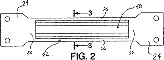
ベース部材20は、中央部22及びその対向する端に端部ブラケット24を含み、これら各部からなる1部材である。衝撃ビーム10は、ドア100内に通例水平に配置される(図1参照)。端部ブラケット24は、あらゆる適当な手段により、好ましくは溶接により、ドア100のフレームに固定される。
【0011】
端部ブラケット24の形態及び形状は、当該技術分野において公知であり、ドア100に合わせて、その適用を種種変更される。ブラケット24は、別の方法の、又は追加の取り付け機構を含んでもよい。好ましい実施例において、端部ブラケット24は、ベース部材20と一体になる。望むのであれば、端部ブラケット24は、中央部から分離してつくられ、あらゆる適当な手段により、好ましくは溶接により、中央部22に取り付けられてもよい。
【0012】
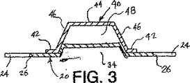
中央部22は、対向端部50及び側縁部26を含み、側縁部26は、ビームの製作において、挿入材40の周りで曲げ加工される。中央部22は、更に縦方向に引っ込んだ部分30を画成し、これにより、その構造の無欠性及び強度が強まり、挿入材40が製作過程において本体20に配置されるとき、その配置により機能を提供する。曲げ加工されるとき(図4、図5参照)、側縁部26は、それ自体の上に折り重ねられ、溝部28を画成する。引込み部30は、側縁部26から離間して配置され、ビーム10の長さに沿って伸長する。引込み部30は、図5中、帽子形状の形態を有するよう図示される。当業者にとって、代替形状は明らかであろう。引込み部30は凹部34を画成する。
【0013】
ベース部材20は、十分な強度を有する比較的低価格の材料からつくられ、衝撃の間中、ドアに取り付けられたままであり、補強用部材を支持する。好ましい実施例において、ベース部材20は、低価格の軟鋼からつくられる。ベース部材20は、他の材料からつくられてもよい。
【0014】
図1、図3及び図5に示す如く、補強用部材は、その長さに亘って、帽子形状の断面を有するとともに、足部42、ブリッジ部44及び相互に接続している側壁部46を含む。側壁部46は、ブリッジ部44の夫々の側から伸長する。足部42は、側壁部46から外方へ伸長するとともに、通例互いに同一平面にある。「帽子形状」は、実質的な強度を有する本体部が1対の対向足部から伸長するいかなる断面にも当てはまる。側壁部46の距離は、通例引込み部30の幅と同じであり、これにより、本体20に挿入材40を配置することを助ける。挿入材40の形状及び形態は、適用により種種変更する。
【0015】
足部42は、曲げ加工された側縁部26により、溝部28内に固定される。溝部28は、補強用部材40の足部42が、衝撃の間中、ベース部材20の長さに対して相対的、且つその長さに沿ってスライドすることを許容する。このスライドによる相対的な移動は、衝撃の圧力が、補強用部材40及びベース部材20を曲げるのを防止することに役立つ。その結果、衝撃の間の基盤20に沿った補強用部材40のスライドが、ドアビーム10の衝撃強さを向上させる。
【0016】
好ましい実施例において、補強用部材40は、基盤部20の対向端部50から等距離に配置される。ビームの中央部において、最大の強度が要求されるからである。補強用部材40の長さ及び本体20に沿ったその配置は、適用により種種変更する。
【0017】
補強用部材40は、ベース部材20より比較的高い弾性係数、及び/又は、高い引張り強さを有する材料からつくられる。好ましい実施例において、補強用部材40は、マルテンサイト・スチールからつくられる。適切なマルテンサイト・スチールの一例は、インランド・M220(商標)・超高強度・低合金スチールである。マルテンサイト・スチールによる補強用部材40は、軟鋼によるベース部材20よりも高い弾性係数を有する。ベース部材20は、低価格の軟鋼からつくられるため、ドアビーム10の総コストは比較的低い。補強用部材40は、比較的低い総コストを可能にする一方、ドアビーム10の衝撃強さを向上させる。
II. 製作方法
容易に予想できるように、ベース部材20は、プレス加工される。また、補強用部材40は、当業者にとってよく知られているプロセスにしたがって、ロール成形加工される。挿入材40は、本体20の側縁部26が挿入材40の足部42の周りで曲げ加工される最終のプレス加工操作の前に、本体20夫々に対して1つを運搬するスピードで、ロール成形加工される。プレス加工操作の丁度前に、補強用部材40は、ベース部材20の上に配置される。挿入材及び本体を適当にかみ合わせて、すなわち入れて重ね合わせるという特徴は、本体上に挿入材を適当に位置決めすることを容易にする。挿入材40が、適当に位置決めされた後、ベース部材20の側縁部26は、折り曲げられて、足部42の周りで曲げ加工される。
【0018】
溶接、曲げ加工、またはレーシングは、補強用部材40をベース部材20に対して更に固定するために使用されてもよい。使用されるときは、これらの方法は、衝撃の間中、補強用部材40が、ベース部材20を横切ってスライドすることを防止してもよい。
【0019】
前の、同時の、又は後の曲げ加工のステップの間に、端部ブラケット24は、その形状(例えば、角度、穴、隆起及び他の形を含む)が形成されることが可能である。製作の代替方法において、ベース部材20及び補強用部材40の双方とも、ロール成形加工される。ロール成形加工された補強用部材40は、(縁部26が曲げ加工される前に)ロール成形加工されたベース部材20の上に配置され、その側縁部は、後のロール成形加工の操作により足部42の周りで曲げ加工される。端部ブラケット24は、前のプレス加工操作、ロール成形加工操作、及び/又は、後のプレス加工操作によりつくることができる。連続したビーム・ウェブは、その後個々のビームに切断される。
【0020】
上述した説明は、本発明の好ましい実施例についてのものである。様々な代替や変更は、特許請求の範囲において定義される本発明の趣旨及びより広い解釈から離れることなく、なされることができ、特許請求の範囲は均等論を含む特許法の原則にしたがって解釈される。
【図面の簡単な説明】
【図1】 本発明のドアビームを含む車両のドアの斜視図である。
【図2】 挿入部材の周りで本体を曲げ加工する前のドアビームの正面図である。
【図3】 図2中、3−3線に沿う断面図である。
【図4】 挿入部材の周りで本体を曲げ加工された本体を示すための、完成後のドアビームの正面図である。
【図5】 図4中、5−5線に沿うドアビームの断面図である。
【符号の説明】
10…ドアビーム
20…ベース部材
26…ベース部材の側縁部
40…挿入部材
42…挿入部材の足部[0001]
[Industrial application fields]
The present invention relates to a door beam of a vehicle, and more particularly to a door beam having a reinforcing insertion member.
[0002]
[Prior art]
Vehicle door beams are widely used in the automotive industry to increase the impact strength of vehicle doors, thereby increasing the safety of automobiles. The door beam is typically roll-formed from steel and includes a hat-shaped beam portion and a pair of collar portions at each end of the beam portion. The door beam is typically secured within the vehicle door by welding its heel portion to the door frame.
[0003]
When considering door beam design, like almost all automotive components, designers seek the right balance of performance, weight, and cost. As part of that balance, it is known that the weight of the door beam can be reduced by making a door beam made of a relatively expensive material. However, this undesirably increases the cost of the door beam. It is also known that the strength of the door beam can be increased by making the door beam from a relatively thick material.
[0004]
In every effort to reduce the total weight, some designers include reinforcing components on the hat-shaped beam. Examples of this approach are US Pat. No. 5,692,797 patented to Dancasiu on Dec. 2, 1997 and US Pat. No. 4 issued to Wilson on Jan. 10, 1989. , 796,946, and others, U.S. Pat. No. 4,684,166, patented on August 4, 1987 to Kanodia. In all of these designs, a relatively flat stiffener is placed on the cap-shaped part of the door beam by bending.
[0005]
[Problems to be solved by the invention]
However, designers continue to pursue additional improvements in the performance / weight / cost balance.
[0006]
[Means for Solving the Problems]
The above-mentioned problems are overcome in the application of the present invention, but in this application of the present invention, the door beam is inserted into a relatively low-strength body by bending and has a hat-shaped insert having a relatively high strength. including. In a preferred embodiment, the insert is made from martensite and the beam is made from mild steel.
[0007]
The present invention has various advantages over the prior art. First, the majority of door beams are made from relatively inexpensive materials. Second, the reinforcing member provides the necessary impact strength only where it is needed, thus reducing the overall weight and cost of the door beam. Thirdly, the beam is produced in various lengths by changing only the length of the base member without having to change the length of the reinforcing member.
[0008]
These and other objects, advantages and features of the present invention will be more fully understood and appreciated by reference to the preferred embodiments and detailed description of the drawings.
[0009]
DETAILED DESCRIPTION OF THE INVENTION
As a means of disclosure, but not as a limitation, a door beam made in accordance with a preferred embodiment of the present invention is illustrated in FIGS.
I. Door Beam Creation The
[0010]
The
[0011]
The shape and shape of the
[0012]
The
[0013]
The
[0014]
As shown in FIGS. 1, 3 and 5, the reinforcing member has a hat-shaped cross section over its length, and includes a foot portion 42, a
[0015]
The foot portion 42 is fixed in the groove portion 28 by the
[0016]
In a preferred embodiment, the reinforcing
[0017]
The reinforcing
II. Manufacturing Method As can be easily predicted, the
[0018]
Welding, bending, or lacing may be used to further secure the reinforcing
[0019]
During the previous, simultaneous or subsequent bending step, the
[0020]
The above description is for the preferred embodiment of the present invention. Various alternatives and modifications can be made without departing from the spirit and broader interpretation of the invention as defined in the claims, which are interpreted according to the principles of patent law, including doctrine of equivalents. Is done.
[Brief description of the drawings]
FIG. 1 is a perspective view of a vehicle door including a door beam according to the present invention.
FIG. 2 is a front view of a door beam before bending a main body around an insertion member.
3 is a cross-sectional view taken along line 3-3 in FIG.
FIG. 4 is a front view of the door beam after completion to show the main body having the main body bent around the insertion member.
FIG. 5 is a cross-sectional view of the door beam taken along line 5-5 in FIG.
[Explanation of symbols]
DESCRIPTION OF
Claims (6)
一対の側縁部と一対の対向端部とを含む本体であって、各前記側縁部はそれ自身の上に曲げ加工されて溝部を画成し、前記溝部がお互いの方へ開口し、各前記対向端部がドアに固定される一体ブラケットを形成し、前記本体が前記側縁部間に縦方向に引っ込んだ引込み部を更に備え、前記引込み部は対向する側部を備え、前記本体が本体材料からつくられている、本体と、
一対の対向する脚部を備えた帽子形状の補強用挿入部材であって、各前記脚部が互いに離間するように伸長する足部を備え、各脚部が前記引込み部の側部の一つと係合し、各前記足部が前記溝部の1つの内部にあり、各前記側縁部が前記足部の一つの両面に係合している、補強用挿入部材とを備えており、
前記各側縁部が、前記足部の一つの回りに曲げ加工され、前記挿入部材は前記本体より短く且つ前記ブラケットの間に配置されて、これによって、前記挿入部材は前記本体内でスライドすることができることを特徴とする、車両のドアビーム。In the vehicle door beam,
A body including a pair of side edges and a pair of opposing ends, each side edge being bent over itself to define a groove, the grooves opening toward each other; Each of the opposing end portions forms an integrated bracket fixed to the door, the main body further includes a retracting portion that is retracted in the vertical direction between the side edges, and the retracting portion includes opposing side portions, the main body Is made from the body material,
A hat-shaped reinforcing insertion member having a pair of opposing legs, each leg including a leg extending so as to be separated from each other, and each leg is one of the side parts of the retracting part. Engaging reinforcing members, wherein each said foot is inside one of said grooves, and each said side edge is engaged with one side of said foot,
Each side edge is bent around one of the legs, and the insertion member is shorter than the body and disposed between the brackets so that the insertion member slides within the body. A door beam of a vehicle, characterized in that it can .
挿入部材材料からつくられている前記挿入部材は、前記本体の材料よりも高い強度を有していることを特徴とする、車両のドアビーム。The vehicle door beam according to claim 1,
The vehicle door beam according to claim 1, wherein the insertion member made of an insertion member material has higher strength than the material of the main body.
前記挿入部材は、マルテンサイト・スチールであることを特徴とする、車両のドアビーム。In the door beam of the vehicle according to claim 2,
The vehicle door beam according to claim 1, wherein the insertion member is martensite steel.
谷部を画定する帽子形状の補強用挿入部材であって、長さと互いに離間するように伸長する一対の対向する足部とを有し、比較的高い強度の材料からつくられている、補強用挿入部材と、
前記挿入部材の谷部内に係合して嵌まる引込み部を有する本体であって、前記対向する足部の周りで曲げ加工された一対の対向する縁部であって、各縁部が各前記対向する足部の両面に係合する一対の対向する縁部を有し、ドアに固定されるブラケットとして一体に形成された一対の対向端部であって、前記ブラケットが前記挿入部材の両端部を越えて伸長している一対の対向端部を更に有している、本体とを具備しており、
前記挿入部材は前記本体より短く且つ前記ブラケットの間に配置され、これによって、前記挿入部材は前記本体内でスライドすることができることを特徴とする、ドアビーム。In the door beam,
Reinforcing insert in the shape of a hat that defines a trough, having a pair of opposing feet that extend away from the length and made of a relatively high strength material An insertion member;
A main body having a retracting portion that engages and fits into a valley portion of the insertion member, and is a pair of opposing edge portions that are bent around the opposing foot portions. A pair of opposing edges having a pair of opposing edges that engage with both sides of the opposing foot and are integrally formed as a bracket fixed to the door, wherein the brackets are opposite ends of the insertion member Further comprising a body having a pair of opposing ends extending beyond
The door beam , wherein the insertion member is shorter than the main body and disposed between the brackets, whereby the insertion member can slide within the main body .
挿入部材材料からつくられている前記挿入部材は、前記本体の材料よりも高い強度を有していることを特徴とする、ドアビーム。The door beam according to claim 4 ,
A door beam characterized in that the insert member made of insert member material has a higher strength than the material of the body.
前記挿入部材は、マルテンサイト・スチールからつくられることを特徴とする、ドアビーム。The door beam according to claim 5 ,
The door beam is made of martensite steel.
Applications Claiming Priority (2)
| Application Number | Priority Date | Filing Date | Title |
|---|---|---|---|
| US21779100P | 2000-07-12 | 2000-07-12 | |
| PCT/US2001/021902 WO2002004240A1 (en) | 2000-07-12 | 2001-07-12 | Roll-formed and stamped doorbeam |
Publications (2)
| Publication Number | Publication Date |
|---|---|
| JP2004507396A JP2004507396A (en) | 2004-03-11 |
| JP4072050B2 true JP4072050B2 (en) | 2008-04-02 |
Family
ID=22812532
Family Applications (1)
| Application Number | Title | Priority Date | Filing Date |
|---|---|---|---|
| JP2002508925A Expired - Fee Related JP4072050B2 (en) | 2000-07-12 | 2001-07-12 | Vehicle door beam and manufacturing method thereof |
Country Status (9)
| Country | Link |
|---|---|
| US (1) | US6622450B2 (en) |
| EP (1) | EP1299257B1 (en) |
| JP (1) | JP4072050B2 (en) |
| AU (1) | AU2001282882A1 (en) |
| CA (1) | CA2394550C (en) |
| DE (1) | DE60125768T2 (en) |
| ES (1) | ES2278771T3 (en) |
| MX (1) | MXPA02005790A (en) |
| WO (1) | WO2002004240A1 (en) |
Families Citing this family (28)
| Publication number | Priority date | Publication date | Assignee | Title |
|---|---|---|---|---|
| US20040201255A1 (en) * | 1998-10-19 | 2004-10-14 | Martin Jonsson | Lightweight beam |
| DE10128198C2 (en) * | 2001-06-11 | 2003-12-24 | Benteler Automobiltechnik Gmbh | Side impact beam for a motor vehicle and blank as a semi-finished product for a side impact beam |
| DE10212792B4 (en) * | 2002-03-22 | 2005-05-12 | Benteler Automobiltechnik Gmbh | Side impact beams |
| US6679540B1 (en) * | 2003-03-07 | 2004-01-20 | Trim Trends Co., Llc | Epoxy bonded laminate door beam |
| US6971691B1 (en) * | 2004-06-25 | 2005-12-06 | Shape Corporation | Vehicle bumper beam |
| KR100588849B1 (en) * | 2004-08-04 | 2006-06-14 | 현대자동차주식회사 | Hybrid type front bumper beam structure |
| DE102005036292B4 (en) * | 2005-03-21 | 2007-11-08 | Dura Automotive Plettenberg Entwicklungs- Und Vertriebs Gmbh | Side impact beam for a motor vehicle |
| JP4481254B2 (en) * | 2006-02-02 | 2010-06-16 | 本田技研工業株式会社 | Airbag device |
| SE530404C2 (en) * | 2006-09-11 | 2008-05-27 | Gestamp Hardtech Ab | Vehicle door and impact protection beam for such |
| TWI338390B (en) * | 2007-07-12 | 2011-03-01 | Ind Tech Res Inst | Flexible thermoelectric device and manufacturing method thereof |
| US7866716B2 (en) | 2008-04-08 | 2011-01-11 | Flex-N-Gate Corporation | Energy absorber for vehicle |
| SE532302C2 (en) * | 2008-04-24 | 2009-12-08 | Gestamp Hardtech Ab | Impact guard beam |
| DE102008063027B4 (en) * | 2008-12-23 | 2023-06-15 | Dr. Ing. H.C. F. Porsche Aktiengesellschaft | motor vehicle door |
| DE102009011378B4 (en) * | 2009-03-05 | 2012-03-22 | Benteler Automobiltechnik Gmbh | Door impact beams |
| BR112012014617B1 (en) * | 2009-12-17 | 2019-12-24 | Volvo Lastvagnar Ab | vehicle and vehicle door reinforcement structure |
| RU2473431C1 (en) * | 2011-07-13 | 2013-01-27 | Общество с ограниченной ответственностью "МОБИЛЬ" - ООО "Мобиль" | Method of making safety rail |
| US8727421B2 (en) | 2011-08-31 | 2014-05-20 | Shape Corp. | Door beam assembly with roll formed beam |
| RU2501669C2 (en) * | 2011-12-22 | 2013-12-20 | Общество с ограниченной ответственностью "МОБИЛЬ" (ООО "Мобиль") | Method of making safety rail |
| WO2014018511A1 (en) * | 2012-07-23 | 2014-01-30 | Magna International Inc. | Vehicle door |
| DE102013200073A1 (en) * | 2012-09-03 | 2014-03-06 | Magna International Inc. | bumper beam |
| DE102012215598B4 (en) * | 2012-09-03 | 2019-02-14 | Magna International Inc. | impact beams |
| SE537087C2 (en) * | 2013-03-13 | 2014-12-30 | Gestamp Hardtech Ab | Bumper beam |
| JP5997836B2 (en) * | 2013-04-03 | 2016-09-28 | 本田技研工業株式会社 | Vehicle door |
| DE102015112499A1 (en) * | 2015-07-30 | 2017-02-02 | Dr. Ing. H.C. F. Porsche Aktiengesellschaft | Door impact beams |
| US10065587B2 (en) | 2015-11-23 | 2018-09-04 | Flex|N|Gate Corporation | Multi-layer energy absorber |
| KR101896325B1 (en) | 2016-11-15 | 2018-09-07 | 현대자동차 주식회사 | Impact beam structure of CFRP door for vehicle |
| KR20180068108A (en) * | 2016-12-13 | 2018-06-21 | 현대자동차주식회사 | Door structure for vehicle |
| US10350973B2 (en) | 2017-07-17 | 2019-07-16 | Ford Global Technologies, Llc | Bracket to connect interior door trim grab handle with integrated window regulator carrier |
Family Cites Families (13)
| Publication number | Priority date | Publication date | Assignee | Title |
|---|---|---|---|---|
| JPS5639698Y2 (en) * | 1975-10-01 | 1981-09-16 | ||
| US4307911A (en) * | 1980-02-04 | 1981-12-29 | The Budd Company | Reinforcement means for resisting side impacts against an automobile door |
| US4684166A (en) * | 1986-05-19 | 1987-08-04 | General Motors Corporation | Vehicle door impact beam and stabilizing assembly |
| US4796946A (en) * | 1987-09-04 | 1989-01-10 | Inland Steel Company | Automotive vehicle door and bar reinforcement |
| US5404690A (en) | 1993-03-26 | 1995-04-11 | Crescive Die & Tool, Inc. | Impact beam assembly method and apparatus |
| EP0685355A1 (en) | 1994-05-30 | 1995-12-06 | Schade Kg | Impact beam |
| US5480189A (en) * | 1994-08-12 | 1996-01-02 | Ford Motor Company | Automotive vehicle frame |
| JP3763858B2 (en) * | 1995-02-14 | 2006-04-05 | ユニプレス株式会社 | Guard beam for automobile door |
| US5580120A (en) * | 1995-02-23 | 1996-12-03 | Mascotech Tubular Products, Inc. | Vehicle door intrusion beam |
| US5785376A (en) * | 1995-06-21 | 1998-07-28 | Mascotech Tubular Products, Inc. | Vehicle door beam |
| DE19647334B4 (en) * | 1996-11-15 | 2004-07-15 | Benteler Ag | Side impact beam for a passenger car |
| US6096403A (en) * | 1997-07-21 | 2000-08-01 | Henkel Corporation | Reinforced structural members |
| AU1064799A (en) | 1997-10-03 | 1999-04-27 | Pullman Industries, Inc. | Protective bar for vehicle door |
-
2001
- 2001-07-12 MX MXPA02005790A patent/MXPA02005790A/en active IP Right Grant
- 2001-07-12 US US09/904,066 patent/US6622450B2/en not_active Expired - Fee Related
- 2001-07-12 JP JP2002508925A patent/JP4072050B2/en not_active Expired - Fee Related
- 2001-07-12 WO PCT/US2001/021902 patent/WO2002004240A1/en active IP Right Grant
- 2001-07-12 AU AU2001282882A patent/AU2001282882A1/en not_active Abandoned
- 2001-07-12 EP EP01961633A patent/EP1299257B1/en not_active Expired - Lifetime
- 2001-07-12 DE DE60125768T patent/DE60125768T2/en not_active Expired - Fee Related
- 2001-07-12 CA CA002394550A patent/CA2394550C/en not_active Expired - Fee Related
- 2001-07-12 ES ES01961633T patent/ES2278771T3/en not_active Expired - Lifetime
Also Published As
| Publication number | Publication date |
|---|---|
| CA2394550A1 (en) | 2002-01-17 |
| US20020069609A1 (en) | 2002-06-13 |
| DE60125768D1 (en) | 2007-02-15 |
| ES2278771T3 (en) | 2007-08-16 |
| US6622450B2 (en) | 2003-09-23 |
| EP1299257A1 (en) | 2003-04-09 |
| WO2002004240A1 (en) | 2002-01-17 |
| JP2004507396A (en) | 2004-03-11 |
| EP1299257B1 (en) | 2007-01-03 |
| MXPA02005790A (en) | 2003-01-28 |
| CA2394550C (en) | 2005-12-13 |
| DE60125768T2 (en) | 2007-10-11 |
| AU2001282882A1 (en) | 2002-01-21 |
Similar Documents
| Publication | Publication Date | Title |
|---|---|---|
| JP4072050B2 (en) | Vehicle door beam and manufacturing method thereof | |
| US6824199B2 (en) | Fender arrangement for a motor vehicle | |
| US7448670B2 (en) | Vehicle door reinforcement | |
| JP2010507532A (en) | B-shaped beam with in-plane integrated ribs | |
| US20060043774A1 (en) | Structural assembly having integrated outer and inner reinforced members | |
| US20040130166A1 (en) | Profile for an automobile structural element and corresponding chassis | |
| US6916063B2 (en) | Reinforced structure for rear part of front side rail in vehicle | |
| CA2520296C (en) | Low-profile high-strength vehicle door beam | |
| US20100045073A1 (en) | Beam, and method for making such beam | |
| US20020047288A1 (en) | Side impact beam | |
| JP2005067392A (en) | Bumper structure for automobile | |
| JP2004074834A (en) | Bumper reinforcing material | |
| JP2002019559A (en) | Vehicular reinforcing member | |
| JPH10193944A (en) | Stabilizer for automobile | |
| JP2001010421A (en) | Vehicle bumper device | |
| JP2014198512A (en) | Vehicle hood structure and striker reinforcement material | |
| JP5007325B2 (en) | Deformation elements for automotive impact damping. | |
| JPH04238725A (en) | Impact beam for automobile door | |
| JP3668789B2 (en) | Vehicle door beam mounting structure | |
| KR20020043545A (en) | Method for assembling at least two component metal elements for producing a structure | |
| JP3915269B2 (en) | Car member structure | |
| RU2256563C2 (en) | Reinforcement bar for member of car body and/or chassis | |
| JP2572091Y2 (en) | Automotive door guard beam | |
| JP2008260367A (en) | Front under run protector | |
| JPH10152005A (en) | Interior trim structure for automobile |
Legal Events
| Date | Code | Title | Description |
|---|---|---|---|
| A621 | Written request for application examination |
Free format text: JAPANESE INTERMEDIATE CODE: A621 Effective date: 20040525 |
|
| A131 | Notification of reasons for refusal |
Free format text: JAPANESE INTERMEDIATE CODE: A131 Effective date: 20060630 |
|
| A601 | Written request for extension of time |
Free format text: JAPANESE INTERMEDIATE CODE: A601 Effective date: 20060929 |
|
| A602 | Written permission of extension of time |
Free format text: JAPANESE INTERMEDIATE CODE: A602 Effective date: 20061006 |
|
| A521 | Written amendment |
Free format text: JAPANESE INTERMEDIATE CODE: A523 Effective date: 20061228 |
|
| A131 | Notification of reasons for refusal |
Free format text: JAPANESE INTERMEDIATE CODE: A131 Effective date: 20070326 |
|
| A601 | Written request for extension of time |
Free format text: JAPANESE INTERMEDIATE CODE: A601 Effective date: 20070327 |
|
| A602 | Written permission of extension of time |
Free format text: JAPANESE INTERMEDIATE CODE: A602 Effective date: 20070420 |
|
| A521 | Written amendment |
Free format text: JAPANESE INTERMEDIATE CODE: A523 Effective date: 20070628 |
|
| TRDD | Decision of grant or rejection written | ||
| A01 | Written decision to grant a patent or to grant a registration (utility model) |
Free format text: JAPANESE INTERMEDIATE CODE: A01 Effective date: 20080111 |
|
| A61 | First payment of annual fees (during grant procedure) |
Free format text: JAPANESE INTERMEDIATE CODE: A61 Effective date: 20080118 |
|
| R150 | Certificate of patent or registration of utility model |
Free format text: JAPANESE INTERMEDIATE CODE: R150 |
|
| FPAY | Renewal fee payment (event date is renewal date of database) |
Free format text: PAYMENT UNTIL: 20110125 Year of fee payment: 3 |
|
| LAPS | Cancellation because of no payment of annual fees |