JP4071193B2 - Pipe coupler - Google Patents
Pipe coupler Download PDFInfo
- Publication number
- JP4071193B2 JP4071193B2 JP2003507457A JP2003507457A JP4071193B2 JP 4071193 B2 JP4071193 B2 JP 4071193B2 JP 2003507457 A JP2003507457 A JP 2003507457A JP 2003507457 A JP2003507457 A JP 2003507457A JP 4071193 B2 JP4071193 B2 JP 4071193B2
- Authority
- JP
- Japan
- Prior art keywords
- tongue
- groove
- coupler
- pair
- sealing sleeve
- Prior art date
- Legal status (The legal status is an assumption and is not a legal conclusion. Google has not performed a legal analysis and makes no representation as to the accuracy of the status listed.)
- Expired - Lifetime
Links
Images


Classifications
-
- F—MECHANICAL ENGINEERING; LIGHTING; HEATING; WEAPONS; BLASTING
- F16—ENGINEERING ELEMENTS AND UNITS; GENERAL MEASURES FOR PRODUCING AND MAINTAINING EFFECTIVE FUNCTIONING OF MACHINES OR INSTALLATIONS; THERMAL INSULATION IN GENERAL
- F16L—PIPES; JOINTS OR FITTINGS FOR PIPES; SUPPORTS FOR PIPES, CABLES OR PROTECTIVE TUBING; MEANS FOR THERMAL INSULATION IN GENERAL
- F16L21/00—Joints with sleeve or socket
- F16L21/06—Joints with sleeve or socket with a divided sleeve or ring clamping around the pipe-ends
-
- F—MECHANICAL ENGINEERING; LIGHTING; HEATING; WEAPONS; BLASTING
- F16—ENGINEERING ELEMENTS AND UNITS; GENERAL MEASURES FOR PRODUCING AND MAINTAINING EFFECTIVE FUNCTIONING OF MACHINES OR INSTALLATIONS; THERMAL INSULATION IN GENERAL
- F16L—PIPES; JOINTS OR FITTINGS FOR PIPES; SUPPORTS FOR PIPES, CABLES OR PROTECTIVE TUBING; MEANS FOR THERMAL INSULATION IN GENERAL
- F16L21/00—Joints with sleeve or socket
- F16L21/002—Sleeves or nipples for pipes of the same diameter; Reduction pieces
- F16L21/005—Sleeves or nipples for pipes of the same diameter; Reduction pieces made of elastic material, e.g. partly or completely surrounded by clamping devices
-
- F—MECHANICAL ENGINEERING; LIGHTING; HEATING; WEAPONS; BLASTING
- F01—MACHINES OR ENGINES IN GENERAL; ENGINE PLANTS IN GENERAL; STEAM ENGINES
- F01N—GAS-FLOW SILENCERS OR EXHAUST APPARATUS FOR MACHINES OR ENGINES IN GENERAL; GAS-FLOW SILENCERS OR EXHAUST APPARATUS FOR INTERNAL COMBUSTION ENGINES
- F01N13/00—Exhaust or silencing apparatus characterised by constructional features ; Exhaust or silencing apparatus, or parts thereof, having pertinent characteristics not provided for in, or of interest apart from, groups F01N1/00 - F01N5/00, F01N9/00, F01N11/00
- F01N13/18—Construction facilitating manufacture, assembly, or disassembly
- F01N13/1805—Fixing exhaust manifolds, exhaust pipes or pipe sections to each other, to engine or to vehicle body
- F01N13/1811—Fixing exhaust manifolds, exhaust pipes or pipe sections to each other, to engine or to vehicle body with means permitting relative movement, e.g. compensation of thermal expansion or vibration
-
- F—MECHANICAL ENGINEERING; LIGHTING; HEATING; WEAPONS; BLASTING
- F01—MACHINES OR ENGINES IN GENERAL; ENGINE PLANTS IN GENERAL; STEAM ENGINES
- F01N—GAS-FLOW SILENCERS OR EXHAUST APPARATUS FOR MACHINES OR ENGINES IN GENERAL; GAS-FLOW SILENCERS OR EXHAUST APPARATUS FOR INTERNAL COMBUSTION ENGINES
- F01N13/00—Exhaust or silencing apparatus characterised by constructional features ; Exhaust or silencing apparatus, or parts thereof, having pertinent characteristics not provided for in, or of interest apart from, groups F01N1/00 - F01N5/00, F01N9/00, F01N11/00
- F01N13/18—Construction facilitating manufacture, assembly, or disassembly
- F01N13/1872—Construction facilitating manufacture, assembly, or disassembly the assembly using stamp-formed parts or otherwise deformed sheet-metal
-
- F—MECHANICAL ENGINEERING; LIGHTING; HEATING; WEAPONS; BLASTING
- F16—ENGINEERING ELEMENTS AND UNITS; GENERAL MEASURES FOR PRODUCING AND MAINTAINING EFFECTIVE FUNCTIONING OF MACHINES OR INSTALLATIONS; THERMAL INSULATION IN GENERAL
- F16L—PIPES; JOINTS OR FITTINGS FOR PIPES; SUPPORTS FOR PIPES, CABLES OR PROTECTIVE TUBING; MEANS FOR THERMAL INSULATION IN GENERAL
- F16L19/00—Joints in which sealing surfaces are pressed together by means of a member, e.g. a swivel nut, screwed on or into one of the joint parts
-
- F—MECHANICAL ENGINEERING; LIGHTING; HEATING; WEAPONS; BLASTING
- F16—ENGINEERING ELEMENTS AND UNITS; GENERAL MEASURES FOR PRODUCING AND MAINTAINING EFFECTIVE FUNCTIONING OF MACHINES OR INSTALLATIONS; THERMAL INSULATION IN GENERAL
- F16L—PIPES; JOINTS OR FITTINGS FOR PIPES; SUPPORTS FOR PIPES, CABLES OR PROTECTIVE TUBING; MEANS FOR THERMAL INSULATION IN GENERAL
- F16L21/00—Joints with sleeve or socket
- F16L21/02—Joints with sleeve or socket with elastic sealing rings between pipe and sleeve or between pipe and socket, e.g. with rolling or other prefabricated profiled rings
-
- F—MECHANICAL ENGINEERING; LIGHTING; HEATING; WEAPONS; BLASTING
- F16—ENGINEERING ELEMENTS AND UNITS; GENERAL MEASURES FOR PRODUCING AND MAINTAINING EFFECTIVE FUNCTIONING OF MACHINES OR INSTALLATIONS; THERMAL INSULATION IN GENERAL
- F16L—PIPES; JOINTS OR FITTINGS FOR PIPES; SUPPORTS FOR PIPES, CABLES OR PROTECTIVE TUBING; MEANS FOR THERMAL INSULATION IN GENERAL
- F16L21/00—Joints with sleeve or socket
- F16L21/06—Joints with sleeve or socket with a divided sleeve or ring clamping around the pipe-ends
- F16L21/065—Joints with sleeve or socket with a divided sleeve or ring clamping around the pipe-ends tightened by tangentially-arranged threaded pins
-
- Y—GENERAL TAGGING OF NEW TECHNOLOGICAL DEVELOPMENTS; GENERAL TAGGING OF CROSS-SECTIONAL TECHNOLOGIES SPANNING OVER SEVERAL SECTIONS OF THE IPC; TECHNICAL SUBJECTS COVERED BY FORMER USPC CROSS-REFERENCE ART COLLECTIONS [XRACs] AND DIGESTS
- Y10—TECHNICAL SUBJECTS COVERED BY FORMER USPC
- Y10S—TECHNICAL SUBJECTS COVERED BY FORMER USPC CROSS-REFERENCE ART COLLECTIONS [XRACs] AND DIGESTS
- Y10S285/00—Pipe joints or couplings
- Y10S285/913—Interdigitating
Landscapes
- Engineering & Computer Science (AREA)
- General Engineering & Computer Science (AREA)
- Mechanical Engineering (AREA)
- Chemical & Material Sciences (AREA)
- Combustion & Propulsion (AREA)
- Flanged Joints, Insulating Joints, And Other Joints (AREA)
- Joints With Sleeves (AREA)
- Exhaust Silencers (AREA)
Description
発明の分野
この発明は、パイプカップリングに関し、より特定的には、2つのパイプの端部を突合せ継ぎで接合するために特に適合されたタイプのパイプカップリングに関する。このタイプのパイプカップリングは、当該技術分野においてはしばしばパイプカプラと称する。
The present invention relates to pipe couplings and more particularly to a type of pipe coupling that is particularly adapted for joining the ends of two pipes with a butt joint. This type of pipe coupling is often referred to in the art as a pipe coupler.
発明の背景
特に自動車産業においては、自動車エンジン排気システムにおいて2つのパイプを合わせて接続するためのパイプカップリングに対する必要性がある。たとえば、自動車排気システムの修理または整備においてマフラと触媒コンバータとの間でパイプを切断して、ここでカプラと称する特別なカップリングを用いて新しいマフラを装着することにより、マフラを交換することが一般的な慣例となってきている。この使用例において、カプラは2つのパイプを、排気ガス漏れに抗する良好な封止を備え、かつ高い引き離し強度を有する突合せ継ぎで接合できなければならない。突合せ継ぎの使用は、テールパイプからマフラまでの重ね継ぎにおいて共通に用いられる溝穴付きパイプ端部に対する必要性をなくす利点を有する。
BACKGROUND OF THE INVENTION There is a need for a pipe coupling to connect two pipes together in an automotive engine exhaust system, particularly in the automotive industry. For example, a muffler can be replaced by cutting a pipe between the muffler and the catalytic converter and installing a new muffler using a special coupling, here called a coupler, in the repair or maintenance of an automobile exhaust system. It has become a common practice. In this use case, the coupler must be able to join the two pipes with a butt joint that has a good seal against exhaust gas leakage and has a high peel strength. The use of a butt splice has the advantage of eliminating the need for a slotted pipe end commonly used in lap splices from the tail pipe to the muffler.
先行技術においては、自動車産業により求められる機械的強度、排気ガス封止特性および長い耐用寿命の要件を満たすパイプカップリングを提供する試みがなされてきた。しかしながら、先行技術は今日の要件に関して満たされない点を多く残している。 In the prior art, attempts have been made to provide pipe couplings that meet the requirements of mechanical strength, exhaust gas sealing properties and long service life required by the automotive industry. However, the prior art leaves many points that are not met with today's requirements.
1941年1月7日にモリス(Morris)に認可された米国特許第2,227,551号は、クランプシェルと合わせて結合されるべきパイプとの間に配置される円筒状の金属スリーブおよびガスケットを含むパイプカップリングを記載する。金属スリーブは、開放しており、対向する端部を備えるが、該端部は、カップリングが締められた場合にともに合わせられる相補的な舌部と窪みとを有する。 U.S. Pat. No. 2,227,551 granted to Morris on January 7, 1941 is a cylindrical metal sleeve and gasket placed between a clamp shell and a pipe to be joined together A pipe coupling containing is described. The metal sleeve is open and has opposing ends, which have complementary tongues and depressions that are mated together when the coupling is tightened.
1977年11月1日にカッセル(Cassel)に認可された米国特許第4,056,273号は、パイプ重ね継ぎのためのカップリングを記載するが、これはより小さな直径のパイプの端部の周りに配置され、より大きな直径のパイプの端部に抗して当接する封止リングを含む。クランプ装置は、より大きな直径のパイプの端部および封止リングを取り囲んでこれらと重なるクランプバンドを有する。封止リングは、互いに相互係合する対向する周方向端部を含み、該封止リング端部の少なくとも一方は傾斜した表面を有し、該傾斜した表面は他方の封止リング端部と係合して、内側パイプを覆うリングをクランピングする間に、リングを互いに対して軸方向に移動させ、それによりリング端部間でのリングの封止をもたらす。 U.S. Pat. No. 4,056,273, granted to Cassel on November 1, 1977, describes a coupling for pipe lap joints, which is the end of a smaller diameter pipe. It includes a sealing ring disposed around and abutting against the end of a larger diameter pipe. The clamping device has a clamping band that surrounds and overlaps the ends of the larger diameter pipe and the sealing ring. The sealing ring includes opposing circumferential ends that interengage with each other, at least one of the sealing ring ends having a sloped surface, the sloped surface being associated with the other sealing ring end. Together, while clamping the rings covering the inner pipe, the rings are moved axially relative to each other, thereby providing a seal of the ring between the ring ends.
この発明の一般的な目的は、先行技術のある不利点を克服する改良されたカプラを提供することである。 A general object of the present invention is to provide an improved coupler that overcomes certain disadvantages of the prior art.
発明の概要
この発明に従うと、流体の漏れに抗する良好な封止をもたらし高い引き離し強度を示す突合せ継ぎで一対のパイプを接合するためのカプラが提供される。これは、高いクランプ
荷重を付与することが可能なバンドクランプにおいて改良された封止スリーブを設けることにより達成される。さらに、この発明は自動車エンジン排気システムにおいて適用するためのカプラに用いるよう特に適合される。
SUMMARY OF THE INVENTION In accordance with the present invention, a coupler is provided for joining a pair of pipes at a butt joint that provides a good seal against fluid leakage and exhibits high peel strength. This is achieved by providing an improved sealing sleeve in the band clamp that can apply high clamping loads. Furthermore, the present invention is particularly adapted for use in couplers for application in automotive engine exhaust systems.
さらに、この発明に従うと、低コストでの大量生産に適合され、設置が簡単であり、高い引き離し強度を備えて、漏れに抗する良好なガス封止を示し、かつ長い耐用寿命を有する改良されたカプラが提供される。 Furthermore, according to this invention, it is adapted for low-cost mass production, easy to install, with high pull-out strength, good gas seal against leakage and having a long service life A coupler is provided.
さらに、この発明に従うと、ばね部材との側部端縁の締まり嵌めによって特徴付けられる舌部および溝を有する封止継手(tongue and groove sealing joints)を備えて鋼により構成される、パイプカプラのための改良された封止スリーブが提供される。 Furthermore, in accordance with the present invention, a pipe coupler constructed of steel with tongue and groove sealing joints characterized by an interference fit of the side edges with the spring member. An improved sealing sleeve is provided.
添付の図面と併せ、以下の詳細な説明からこの発明の完全な理解が得られるであろう。 A full understanding of the invention can be obtained from the following detailed description taken in conjunction with the accompanying drawings, in which:
発明を実行するためのベストモード
図面を参照して、この発明の2つの例示的な実施例が、特に自動車エンジン排気システムにおいて用いるよう適合されるパイプカプラにおいて示される。説明が進むにつれて、この発明は多くの異なった用途において、かつさまざまな態様の実施例において有用であることが理解されるであろう。
Best Mode for Carrying Out the Invention Referring to the drawings, two exemplary embodiments of the present invention are shown in a pipe coupler adapted specifically for use in an automobile engine exhaust system. As the description proceeds, it will be appreciated that the invention is useful in many different applications and in various embodiments.
発明の第1の実施例
この発明の第1の実施例を図1〜7に示す。カプラ10は突合せ継ぎにおいて一対のパイプ12および14を接続するよう適合されるが、これはパイプ間に良好なガス封止と強力な機械的接続とをもたらす。パイプ12および14は、製造公差のある、同じ呼び径を有する。パイプ12および14の端部は、互いに対して軸方向に整列して合わせ目22で接する。カプラは、パイプの対を取り囲み、パイプの端部を覆うよう適合されるクランプバンド18を含むクランプ16を含む。クランプバンド18は開放スリーブとして形成され、横方向に延在しかつ対向するフランジ19および21で終端する。クランプ16はまたクランプを締めてクランプバンドの周方向長さを減じるようクランプバンドに接続される締め付け機構24をも含む。分割封止スリーブ26は、クランプバンド18内に配置され、第1および第2の周方向端部28および32を有するが、これらはそれぞれ、クランプが締められた場合にクランプバンドによって分割封止スリーブが周方向に押しつぶされた場合に、互いに接触するよう対向する関係で封止構造を備える。封止スリーブ26は、封止スリーブ26の対向する周方向端部28および32に設けられる一対の舌部および溝を有する封止継手34aおよび34bを含む。封止スリーブ26の対向する端部28および32間の開口またはギャップは、フランジ19および21間のギャップと重ならないように、クランプバンド18に対して周方向に場所決めされる。クランプ16が締め付け機構24によって締められた場合に、封止スリーブ26はクランプバンドによって周方向に押しつぶされ、舌部および溝を有する封止継手34を閉鎖させて、パイプの合わせ目22から大気への漏れに抗するガス封止をもたらす。
First Embodiment of the Invention A first embodiment of the present invention is shown in FIGS. The
クランプ16自体は公知の構造であり、1965年9月16日にカッセルに認可された米国特許第3,905,623号に記載されるが、その開示の全体を引用により本願明細書に援用する。上述のように、クランプ16はクランプバンド18を含み、これは開放スリーブとして形成されて横方向に延在する対向するフランジ19および21で終端する。クランプはまた、クランプバンドに接続される締め付け機構24をも含む。締め付け機構は、クランプバンド18のフランジ19および21間に配置されるスプラインまたは反発部材23を含む。1対のボルト25がフランジ、反発部材および押し込み棒27における整列された開口を通じて延在するが、締め付け機構を起動するためにねじ切りナット29
が押し込み棒27に抗して取り付けられる。カプラ10を以下により詳細に説明する。
The
Is attached against the
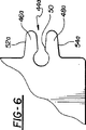
分割封止スリーブ26はシートメタルから、好適にはステンレススチールから作られ、図4に示すように平坦状態でスタンピング動作によって形成され、クランプバンド18に挿入するために円形スリーブに予め成型される。舌部および溝を有する封止継手34aおよび34bは、パイプ端部の合わせ目22が舌部および溝を有する封止継手の対の間に配置され得るように、分割封止スリーブ26上で軸方向に離れた関係で配置される。舌部および溝を有する封止継手34aおよび34bは同じ構造であり、図4〜図6に示す継手34aを参照して説明する。継手34aは封止スリーブ26の端部28において溝36aを含む。溝36aは、封止スリーブの端部28から溝の深さが増すにつれて互いに向かって収束する側部端縁38aおよび42aによって境界を設けられる。継手34aはまた、溝36aと整列してスリーブの端部32から延在する舌部44aをも含む。舌部44aはリリーフノッチ50によって分離される2つのばね部材46aおよび48aを含む。舌部44aは、溝36aの側部端縁38aおよび42aと同じ方向に収束する、ばね部材上の収束する側部端縁52aおよび54aを備えて形成される。
The split
溝36aの側部端縁38aおよび42aは、示されるように各々半径を備えて形成される溝の口の角および溝の底の角を除いてはまっすぐである。溝の側部端縁は例えば約18°の収束の角度を有し、すなわち、各側部端縁が溝の中心線から9°の角度で延在する。舌部44aの側部端縁52aおよび54aは、示されるように半径を備えて形成されるそれぞれの角の間でまっすぐに延在する。舌部部材46aおよび48aが応力を受けない状態または自由な状態にある場合、側部端縁52aおよび54aはたとえば約12°の収束角度を有し、すなわち各側部端縁が舌部44aの中心線と6°の角度をなす。リリーフスロット50は好適には鍵穴型であり、舌部の中心線に対して対称的に配置される。舌部部材46aおよび48aは弾性的でありかつ片持ちばねアームを構成する。舌部部材は、これらが嵌め合う溝に入った場合に舌部の平面において互いに向かって偏向し、溝36aの側部端縁との接触を保ってガス漏れに抗する封止をもたらす。
The side edges 38a and 42a of the
製造された状態でのパイプ10および12は、特定される許容公差範囲を備えた特定される呼び径を有し、該範囲内で実際のパイプ直径は変動し得る。従って、パイプ10および12は同じ呼び径を有すけれども、異なった実際の直径を有し得る。直径の最大の差は、一方のパイプが公差範囲の最小値での実際の直径を有し、他方のパイプが公差範囲の最大値での実際の直径を有する場合に生じ得る。
As manufactured, the
使用においては、組み立てられた締められない状態でのカプラ10は、パイプ12および14の当接された端部を覆って位置決めされ、パイプ端部の合わせ目は舌部および溝を有する封止継手34aおよび34bの間に場所決めされる。この位置において、クランプ16はナット27をボルト29に締めることにより締め付ける準備ができている。クランプ16の締め付けが進むにつれて、舌部44aおよび44bの外側端部がそれぞれの溝36aおよび36bに入り、舌部の側部端縁がそれぞれの溝の側部端縁と、間に摺動摩擦係合が存在するように、係合する。両方のパイプ端部が同じ実際の直径を有すると仮定すると、クランプ16の締め付けがその最終的な締め付け状態に到達した場合に、両方の舌部が同じ貫入深さでそれぞれの溝に入る。もし両方のパイプの実際の直径が公差範囲の最大値であれば、貫入は最小限の深さで起こり、封止係合は、図7に示すように封止継手34a上のポイントAおよびBならびに封止継手34b上のポイントAおよびBで生じる。これに対し、もし両方のパイプの実際の直径が公差範囲の最小値であれば、貫入は最大限の深さで起こり、封止係合は図7に示すようにポイントCおよびDで生じる。もしパイプの実際の直径が等しく公差範囲の中間値であれば、舌部の貫入の深さは対応して中間の深さになり、封止係合は図7におけるポイントEおよびFで生じる。舌部44aおよび44bのばね部材46aおよび48aは、示される貫入の範囲を通してそれぞれの溝36aおよ
び36bとの係合によって偏向される。これは、舌部および溝の側部端縁間の締まり嵌めをもたらすが、これは良好なガス封止を維持するのに有効である。さらに、ばね部材46aおよび48aの偏向はクランプを締めることを可能にして、スリーブとパイプとの間に十分なクランプ荷重を転送し、これらの間の相対的な運動を防ぎ、パイプの外側表面とスリーブの内側表面との間の漏れに抗して封止する。
In use, the assembled
2つのパイプ12および14が許容パイプ直径公差範囲内での異なった実際の直径を有すると仮定する。この状態においては、クランプ16の最終的な締め付けが達成された場合、その一方側は他方側よりも遠くまで閉鎖され、よって封止スリーブ16の一方側の舌部および溝を有する継手の貫入は他方側よりも大きくなる。これはスリーブを傾け(cock)、傾き角度に依存して、各舌部の両方ではなく片方のばね部材のみがそれぞれの溝と係合して封止係合をもたらし得る。それでも、両方の封止継手34aおよび34bが漏れに抗する封止に有効であるが、なぜならばガス漏れをブロックするためには各舌部の一方のみのばね部材と溝との係合しか必要ではないからである。さらに、両方のばね部材の弾性により、舌部は締め付けの間に圧縮されて、十分なクランプ閉鎖を阻害する恐れのある過剰な干渉を防ぎ得る。こうして、クランプ16の締め付けが最終的な締め付け状態に達すると、クランプバンド18は封止スリーブ26の周りで伸張されて、舌部および溝を有する継手を封止状態に保ち、かつ封止スリーブをパイプ12および14の外側表面およびクランプバンドの内側表面に抗して保持するクランプ力を維持して、パイプの端部間の流体漏れが大気中に流出することを防ぐ。
Assume that the two
発明の第2の実施例
この発明の第2の実施例を説明する。第2の実施例のカプラは、図8および図9に示す分割封止スリーブ26’の異なった構造以外は、図1〜図7のカプラと同じ構造である。封止スリーブ26’は第1の実施例と同じタイプのものであるが、1つの舌部および溝を有する継手60しか有さない。継手60は、スリーブ26’の一方端部により規定される溝62と、スリーブの他方端部によって規定される舌部64とを含む。溝62は対向して配置される側部端縁66aおよび66bを有する。舌部64は対向して配置される側部端縁68aおよび68bを有する。溝62の側部端縁は、溝がその開放端および閉鎖端においてはそれらの間の領域においてよりも広くなるように溝の内向きに延在するアーチ状構造を有する。リリーフスロット72aは側部端縁66aに隣接して配置されて同じ方向に延在し、それによりばね端縁部材74aを形成する。同様に、リリーフスロット72bは側部端縁72aに隣接して配置されて同じ方向に延在し、それによりばね端縁部材74bを形成する。
Second Embodiment of the Invention A second embodiment of the present invention will be described. The coupler of the second embodiment has the same structure as the coupler of FIGS. 1 to 7 except for the different structure of the
舌部64は、まっすぐな側部端縁を備えた矩形であり、溝62の入口の幅よりもいくらか狭く、かつばね端縁部材74aおよび74bの間の最も狭い幅よりもいくらか広い幅を有する。
The tongue 64 is rectangular with straight side edges and has a width that is somewhat narrower than the width of the inlet of the
分割封止スリーブ26’を備えて実現されるカプラの使用において、単一の舌部および溝を有する継手60は、図1〜図7のカプラを参照して説明したのと同様の態様でカプラのクランプの締め付けと同時に、閉鎖される。クランプの締め付けが進行するにつれて、舌部64の外側端部は溝62に入り、舌部の側部端縁は溝のそれぞれの側部端縁と、それらの間に摺動摩擦係合が存在するように、係合する。溝62の側部端縁のばね端縁部材74aおよび74bは、図1〜図7のカプラを参照して説明したのと同様の態様で製造公差範囲内のパイプ12および14の実際のダイメンションのばらつきを受け入れる。もし2つのパイプが等しい値の実際の直径を有していれば、舌部64は実際の直径に対応した量で貫入し、溝の側部端縁と封止係合を生じさせる。もし2つのパイプが異なった実際の直径を有していれば、スリーブはそれに従って立ち上がり、舌部の側部端縁は溝の側部端縁との接触を維持して舌部および溝を有する継手62を通る漏れに抗する封止をもたらす。
また、ばね端縁部材74aおよび74bは、密接な封止係合でのクランプの閉鎖と、パイプの間の相対的な運動を防ぐための十分なクランプ荷重の転送とを阻害するであろう過剰な干渉なしに係合をもたらす。
In the use of a coupler realized with a split sealing sleeve 26 ', the joint 60 with a single tongue and groove is coupled in a manner similar to that described with reference to the coupler of FIGS. At the same time as the clamp is tightened, it is closed. As the clamp tightening proceeds, the outer end of the tongue 64 enters the
Also, the
結論
この発明の説明を特定の実施例を参照して行なってきたが、これを限定的な意味で解釈すべきものではない。ここで、この発明の多くの展開例および修正例が当業者には想起されるであろう。
CONCLUSION While this invention has been described with reference to specific embodiments, this should not be construed in a limiting sense. Many developments and modifications of the invention will now occur to those skilled in the art.
Claims (10)
前記封止スリーブは、少なくとも1つの舌部および溝を有する封止継手を含み、前記溝は前記封止スリーブの一方の周方向端部により規定され、前記舌部は、前記封止スリーブの他方の周方向端部により規定され、前記舌部は前記封止スリーブが周方向に押しつぶされた場合に、前記溝と嵌め合うよう前記溝に対向して配置され、前記舌部および前記溝は各々が第1および第2の側部端縁を有し、前記舌部の第1の側部端縁および前記溝の第1の側部端縁は第1の側部端縁の嵌め合う対をなし、前記舌部の第2の側部端縁および前記溝の第2の側部端縁は第2の側部端縁の嵌め合う対をなし、前記舌部は、両方の前記嵌め合う対に対する初期の係合から最大貫入点に延在する貫入の範囲全体にわたる、前記ノッチとの締まり嵌めを有し、
第1の嵌め合う対の一方側部端縁および第2の嵌め合う対の一方側部端縁はばね部材であり、これにより、クランプが締められた場合に両方の前記側部端縁の嵌め合う対の間に封止係合がもたらされる、カプラ。A coupler for connecting a pair of pipes, wherein the coupler is of a type including a clamp, the clamp including a clamp band adapted to surround the pair of pipes, the pair of pipes being adjacent ends. Are substantially the same diameter and arranged axially aligned with each other, the clamp band is wide enough to overlap each end of the pair of pipes, A clamping mechanism connected to the clamp band and tightening the clamp band; and a split sealing sleeve, the split sealing sleeve is present in the clamp band, and the sealing sleeve is crushed in the circumferential direction by the clamp band Having first and second circumferential ends in opposing relation to contact each other when
The sealing sleeve includes a sealing joint having at least one tongue and a groove, the groove being defined by one circumferential end of the sealing sleeve, the tongue being the other of the sealing sleeve When the sealing sleeve is squeezed in the circumferential direction, the tongue is disposed to face the groove so that the tongue and the groove are respectively fitted to the groove. Has first and second side edges, and the first side edge of the tongue and the first side edge of the groove are mated pairs of first side edges. None, the second side edge of the tongue and the second side edge of the groove make a mating pair of second side edges, and the tongue is both of the mating pairs Having an interference fit with the notch over the entire penetration range extending from an initial engagement to a maximum penetration point;
The one side edge of the first mating pair and the one side edge of the second mating pair are spring members so that when both clamps are tightened, the both side edge fits A coupler that provides a sealing engagement between mating pairs.
前記封止スリーブは、第1および第2の舌部および溝を有する封止継手を含み、前記第1および第2の舌部および溝を有する封止継手は、前記封止継手が前記隣接するパイプ端部の前記合わせ目の対向する側部に配置されて前記封止スリーブが前記パイプ上に場所決めされ得るように、軸方向に離れた関係で前記周方向端部上に場所決めされ、
前記封止継手の各々は、封止スリーブの一方周方向端部によって規定される側部端縁を有するV字型溝と、封止スリーブの他方周方向端部によって規定される側部端縁を有するV字型舌部とを含み、前記舌部は、前記封止スリーブが周方向に押しつぶされた場合に、前記溝と嵌め合うよう前記溝に対向して配置され、前記舌部は、両方の前記嵌め合う対に対する、初期の係合から最大貫入点に延在する貫入の範囲全体にわたる、前記溝との締ま
り嵌めをそれぞれ有し、
各封止継手の舌部の側部端縁のうちの少なくとも1つはばね部材であり、これにより、クランプが締められた場合に前記側部端縁の係合により封止係合がもたらされる、カプラ。A coupler for connecting a pair of pipes, wherein the coupler is of a type including a clamp, the clamp including a clamp band adapted to surround the pair of pipes, the pair of pipes being adjacent ends. Are substantially the same diameter and arranged axially aligned with each other, the clamp band is wide enough to overlap each end of the pair of pipes, A clamping mechanism connected to the clamp band and tightening the clamp band; and a split sealing sleeve, the split sealing sleeve is present in the clamp band, and the sealing sleeve is crushed in the circumferential direction by the clamp band Having first and second circumferential ends in opposing relation to contact each other when
The sealing sleeve includes a sealing joint having first and second tongues and grooves, and the sealing joint having the first and second tongues and grooves is adjacent to the sealing joint. Located on the circumferential end in an axially spaced relationship so that the sealing sleeve can be located on the pipe disposed on the opposite side of the seam of the pipe end,
Each of the sealing joints has a V-shaped groove having a side edge defined by one circumferential end of the sealing sleeve, and a side edge defined by the other circumferential end of the sealing sleeve. A tongue having a V-shape, and the tongue is disposed to face the groove so as to fit into the groove when the sealing sleeve is crushed in the circumferential direction. Each of the mating pairs has an interference fit with the groove over the entire penetration range extending from initial engagement to the maximum penetration point;
At least one of the side edges of the tongue of each sealing joint is a spring member, which provides a sealing engagement by engagement of the side edges when the clamp is tightened. , Coupler.
前記封止スリーブは、前記周方向端部に場所決めされる舌部および溝を有する封止継手を含み、
前記封止継手は、前記封止スリーブの一方周方向端部によって規定される溝と、前記封止スリーブの他方周方向端部によって規定される舌部とを含み、前記舌部は、前記封止スリーブが周方向に押しつぶされた場合に、前記溝と嵌め合うよう前記溝に対向して配置され、前記舌部および溝の一方は、第1および第2の実質的にまっすぐで平行な側部端縁を有し、前記舌部および溝の他方は、第1および第2の凸型アーチ状の側部端縁を有し、前記舌部の第1の側部端縁および前記溝の第1の側部端縁は第1の側部端縁の嵌め合う対をなし、前記舌部の第2の側部端縁および前記溝の第2の側部端縁は第2の側部端縁の嵌め合う対をなし、前記舌部は、両方の前記嵌め合う対に対する初期の係合から最大貫入点に延在する貫入の範囲全体にわたる、前記溝との締まり嵌めを有し、
前記側部端縁の嵌め合う対の少なくとも一方の、少なくとも一方の側部端縁はばね部材であり、これにより、クランプが締められた場合に側部端縁の嵌め合う対の係合により封止がもたらされる、カプラ。A coupler for connecting a pair of pipes, wherein the coupler is of a type including a clamp, the clamp including a clamp band adapted to surround the pair of pipes, the pair of pipes being adjacent ends. Are substantially the same diameter and arranged axially aligned with each other, the clamp band is wide enough to overlap each end of the pair of pipes, A clamping mechanism connected to the clamp band and tightening the clamp band and a split sealing sleeve, the split sealing sleeve being present in the clamp band, and the sealing sleeve being crushed in the circumferential direction by the clamp band Having first and second circumferential ends in opposing relation to contact each other when
The sealing sleeve includes a sealing joint having a tongue and a groove located at the circumferential end;
The sealing joint includes a groove defined by one circumferential end of the sealing sleeve and a tongue defined by the other circumferential end of the sealing sleeve, and the tongue includes the sealing When the stop sleeve is squeezed in the circumferential direction, the sleeve is disposed to face the groove so as to be fitted with the groove, and one of the tongue and the groove is the first and second substantially straight and parallel sides. And the other of the tongue and the groove has first and second convex arched side edges, the first side edge of the tongue and the groove The first side edge is a mating pair of first side edges, and the second side edge of the tongue and the second side edge of the groove are the second side A mating pair of edges, the tongue extending over the entire penetration range extending from the initial engagement to both mating pairs to the maximum penetration point Has an interference fit with said groove,
At least one of the side edge mating pairs is a spring member so that when the clamp is tightened, the side edge mating pair is engaged by engagement. A coupler that provides a stop.
Applications Claiming Priority (2)
| Application Number | Priority Date | Filing Date | Title |
|---|---|---|---|
| US09/886,793 US6758501B2 (en) | 2000-06-23 | 2001-06-21 | Pipe coupler |
| PCT/US2002/019396 WO2003001099A2 (en) | 2001-06-21 | 2002-06-18 | Pipe coupler |
Publications (2)
| Publication Number | Publication Date |
|---|---|
| JP2005509103A JP2005509103A (en) | 2005-04-07 |
| JP4071193B2 true JP4071193B2 (en) | 2008-04-02 |
Family
ID=25389782
Family Applications (1)
| Application Number | Title | Priority Date | Filing Date |
|---|---|---|---|
| JP2003507457A Expired - Lifetime JP4071193B2 (en) | 2001-06-21 | 2002-06-18 | Pipe coupler |
Country Status (8)
| Country | Link |
|---|---|
| US (3) | US6758501B2 (en) |
| EP (2) | EP1481184B1 (en) |
| JP (1) | JP4071193B2 (en) |
| KR (1) | KR100936701B1 (en) |
| AU (1) | AU2002316290A1 (en) |
| CA (1) | CA2461263C (en) |
| MX (1) | MXPA03012059A (en) |
| WO (1) | WO2003001099A2 (en) |
Families Citing this family (68)
| Publication number | Priority date | Publication date | Assignee | Title |
|---|---|---|---|---|
| US6877780B2 (en) * | 2000-06-23 | 2005-04-12 | Breeze-Torca Products, Llc | Clamp for joining tubular bodies |
| KR20040006025A (en) * | 2001-06-08 | 2004-01-16 | 쇼와 덴코 가부시키가이샤 | Metal plate for producing flat tube, flat tube and process for producing the flat tube |
| WO2003002306A2 (en) | 2001-06-29 | 2003-01-09 | Breeze-Torca Products, Llc | Clamp for joining tubular bodies |
| US20040216284A1 (en) * | 2001-09-14 | 2004-11-04 | Belisle John I | Exhaust system clamp |
| EP1581763A1 (en) * | 2003-01-07 | 2005-10-05 | Hans Oetiker AG Maschinen- und Apparatefabrik | Retaining clamp |
| DE10336351B3 (en) * | 2003-08-08 | 2004-11-11 | Rasmussen Gmbh | Pipe clip for joining two pipes or an exhaust gas pipe of a motor vehicle has a transverse axis around which a tensioned clip band is bent at a distance from the middle point of ball zones |
| US7052331B2 (en) * | 2003-09-25 | 2006-05-30 | Maxwell Scott D | Symmetrically adjustable corrosion-resistant battery cable connector |
| AU2004289698B2 (en) * | 2003-11-07 | 2011-01-06 | Norma U.S. Holding Llc | Pipe clamp with integral latch |
| KR101279381B1 (en) * | 2004-02-13 | 2013-07-04 | 노마 유.에스. 홀딩 엘엘씨 | Slotted pipe clamp with opposed flange engagement loops |
| US7490871B2 (en) * | 2004-02-26 | 2009-02-17 | Breeze-Torca Products, Llc | Pipe clamp with button engagement hole |
| MXPA06013531A (en) | 2004-05-25 | 2007-03-01 | Breeze Torca Products Llc | Ribbed pipe clamp with sealing sleeve. |
| US7422246B2 (en) * | 2004-08-26 | 2008-09-09 | Straub Tadco Inc. | Remote pipe coupling system |
| BRPI0517541B1 (en) * | 2004-10-04 | 2018-07-24 | Breeze-Torca Products, Llc | PIPE OVERLIP GASKET, PIPE FOR USE IN CONNECTION WITH A SECOND TUBE AND PIPE CLAMP TO FORM A PIPE SUPPLY JOINT, AND METHOD FOR TELESCOPICALLY COUPLING AN INTERNAL AND EXTERNAL PIPE IN THE OTHER |
| US20060103135A1 (en) * | 2004-11-18 | 2006-05-18 | Michael Scott | Exhaust pipe coupling |
| WO2006055966A2 (en) | 2004-11-19 | 2006-05-26 | Breeze-Torca Products, Llc | Pipe clamp with improved fastener |
| CA2595596C (en) * | 2005-02-10 | 2012-10-02 | Breeze-Torca Products, Llc | Pipe clamp with gasketed center rib |
| FR2884582B1 (en) * | 2005-04-13 | 2010-01-08 | Caillau Ets | DEVICE FOR THE SEALED COUPLING OF TWO SMOOTH TUBES |
| EP1979664B1 (en) * | 2006-01-23 | 2015-06-10 | Straub Werke AG | Clamp for high-pressure tubes |
| ES1064088Y (en) * | 2006-11-07 | 2007-05-01 | Metalurgicas Pabur S L | SEALED UNION DEVICE OF TWO CYLINDRICAL TUBES OF DIFFERENT DIAMETERS |
| US7789434B2 (en) * | 2006-12-01 | 2010-09-07 | Victaulic Company | Coupling with concave bearing surface |
| MX2009008007A (en) * | 2007-02-04 | 2009-08-07 | Breeze Torca Products Llc | Stepped ball joint pipe clamp and pre-attachment components therefor. |
| DE102007010342B4 (en) * | 2007-03-03 | 2019-10-02 | Man Energy Solutions Se | pipe coupling |
| US8628122B2 (en) * | 2007-06-06 | 2014-01-14 | Pridgeon & Clay, Inc. | Pipe compression joint |
| US7571940B2 (en) * | 2007-12-04 | 2009-08-11 | Krausz Metal Industries Ltd. | Pipe coupling with built-in grip |
| US20100101173A1 (en) * | 2008-01-04 | 2010-04-29 | General Electric Company | Wind turbine tower joints |
| AU2009209007B2 (en) * | 2008-01-30 | 2014-07-24 | Norma U.S. Holding Llc | Single-bolt band clamp with gasketed center rib and pipe lap joint using the same |
| US8282136B2 (en) | 2008-06-30 | 2012-10-09 | Mueller International, Llc | Slip on groove coupling with multiple sealing gasket |
| US7644955B1 (en) * | 2008-07-03 | 2010-01-12 | Naris Komolrochanaporn | Quick coupling type fitting |
| DE102008055733B8 (en) * | 2008-11-04 | 2010-05-20 | Kirchhoff Gmbh & Co. Kg | Device for connecting the ends of pipes |
| GB2469105B (en) | 2009-04-02 | 2011-06-22 | Verderg Ltd | Apparatus and method for the connection of conduits |
| US11274777B2 (en) | 2009-06-12 | 2022-03-15 | Romac Industries, Inc. | Pipe coupling |
| US8448993B2 (en) | 2009-06-12 | 2013-05-28 | Romac Industries, Inc. | Pipe coupling |
| RU2012111777A (en) * | 2009-08-28 | 2013-10-10 | Норма Ю.С. Холдинг Ллк | PIPE CLAMP WITH BUSHING AND GASKET |
| JP5722348B2 (en) * | 2010-01-21 | 2015-05-20 | ノーマ・ユー・エス・ホールディング・リミテッド・ライアビリティ・カンパニーNorma U. S. Holding Llc | Pipe clamp with gasket |
| DE102010037318A1 (en) | 2010-09-03 | 2012-03-08 | Kirchhoff Gmbh & Co. Kg | Connection device for exhaust tubes of internal combustion engine, has V-shaped pressure clamp that is engaged to butt-straps protruded from peripheral edge of outer shell, and fastened movably using nut and screw |
| WO2012087340A1 (en) * | 2010-12-23 | 2012-06-28 | Moran Thomas F | Coupling and decoupling apparatus and method |
| KR101045356B1 (en) * | 2011-03-07 | 2011-06-30 | 벽진산업 주식회사 | Coupling pipe of round bar |
| USD696751S1 (en) | 2011-10-27 | 2013-12-31 | Mueller International, Llc | Slip-on gasket |
| USD680630S1 (en) | 2011-11-21 | 2013-04-23 | Mueller International, Llc | Slip-on coupling assembly |
| USD680629S1 (en) | 2011-11-21 | 2013-04-23 | Mueller International, Llc | Slip-on coupling segment |
| US9534715B2 (en) | 2012-01-20 | 2017-01-03 | Mueller International, Llc | Coupling gasket with multiple sealing surfaces |
| US9039046B2 (en) | 2012-01-20 | 2015-05-26 | Mueller International, Llc | Coupling with tongue and groove |
| US9194516B2 (en) | 2012-01-20 | 2015-11-24 | Mueller International, Llc | Slip-on coupling |
| US9500307B2 (en) | 2012-01-20 | 2016-11-22 | Mueller International, Llc | Slip-on coupling gasket |
| US8894100B2 (en) | 2012-03-16 | 2014-11-25 | Romac Industries, Inc. | Fitting with draw mechanism |
| US9168585B2 (en) | 2012-11-02 | 2015-10-27 | Mueller International, Llc | Coupling with extending parting line |
| FR3004505B1 (en) * | 2013-04-11 | 2015-05-08 | Caillau Ets | CLAMPING DEVICE FOR THE SEALED COUPLING OF SMOOTH TUBES |
| US10578234B2 (en) * | 2013-05-02 | 2020-03-03 | Victaulic Company | Coupling having arcuate stiffness ribs |
| US9638365B1 (en) * | 2013-07-05 | 2017-05-02 | Marc Reviel | Multipurpose connector system |
| CN103726576B (en) * | 2013-12-06 | 2016-08-17 | 浙江树人大学 | By interfacing part and the method thereof of axial star plate docking steel pipe |
| DE102014203913A1 (en) | 2014-03-04 | 2015-09-10 | Federal-Mogul Wiesbaden Gmbh | Rifle |
| FR3018333A1 (en) | 2014-03-10 | 2015-09-11 | Saint Gobain Performance Plast | |
| US9863561B2 (en) * | 2014-11-13 | 2018-01-09 | Eliezer Krausz Industrial Development Ltd. | Pipe clamp assembly with stiffening element |
| FR3042016B1 (en) * | 2015-10-01 | 2017-11-24 | Caillau Ets | TIGHTENING CLAMP WITH SPACER |
| AU2016381244B2 (en) | 2015-12-28 | 2019-06-13 | Victaulic Company | Adapter coupling |
| US10605394B2 (en) | 2016-05-16 | 2020-03-31 | Victaulic Company | Fitting having tabbed retainer and observation apertures |
| US10859190B2 (en) | 2016-05-16 | 2020-12-08 | Victaulic Company | Sprung coupling |
| US10533688B2 (en) | 2016-05-16 | 2020-01-14 | Victaulic Company | Coupling having tabbed retainer |
| US10871248B2 (en) * | 2018-02-28 | 2020-12-22 | Mueller International, Llc | Coupling gasket with friction-fit range reducer |
| CN108443611B (en) * | 2018-03-15 | 2019-05-28 | 安徽江淮汽车集团股份有限公司 | A kind of flexible collar assembly |
| CN111237083B (en) * | 2018-11-28 | 2022-01-11 | 海鹰航空通用装备有限责任公司 | Combined spray pipe structure and airplane with same |
| FR3090068B1 (en) * | 2018-12-17 | 2021-03-05 | Caillau Ets | Clamping device comprising a belt and a sealing ring |
| US11421804B2 (en) | 2019-04-19 | 2022-08-23 | Aalberts integrated piping systems APAC, Inc. | Quick installation coupling |
| CN110470407B (en) * | 2019-08-21 | 2021-01-29 | 山东大学 | Mid-infrared laser beam analysis device |
| US11781683B2 (en) | 2019-11-15 | 2023-10-10 | Victaulic Company | Shrouded coupling |
| US11280443B2 (en) | 2020-05-19 | 2022-03-22 | ASC Engineered Solutions, LLC | Insulting support bracket for jacketed pipe system |
| CN114145620B (en) * | 2021-11-04 | 2023-08-08 | 上海飞科电器股份有限公司 | Food processor |
| CN116336274A (en) * | 2023-05-29 | 2023-06-27 | 宁波经济技术开发区恒阳机械有限公司 | Pipeline clamping sleeve |
Family Cites Families (33)
| Publication number | Priority date | Publication date | Assignee | Title |
|---|---|---|---|---|
| US227551A (en) * | 1880-05-11 | Harrow | ||
| US895143A (en) * | 1907-09-06 | 1908-08-04 | Olaus S Augensen | Pipe-clamp. |
| US1864339A (en) * | 1929-04-16 | 1932-06-21 | Thomas & Betts Corp | Pipe coupler |
| US1938974A (en) * | 1933-04-10 | 1933-12-12 | Oldberg Mfg Company | Bushing |
| US1978195A (en) * | 1933-10-21 | 1934-10-23 | Buffalo Pressed Steel Company | Clamp band |
| US2227551A (en) | 1939-06-07 | 1941-01-07 | Jolly L Morris | Pipe coupling and pipe clamp |
| US2495622A (en) * | 1947-02-03 | 1950-01-24 | Northern Indiana Brass Co | Pipe joint |
| US2776153A (en) * | 1948-01-26 | 1957-01-01 | Telford L Smith | Armored gasket for pipe repair clamp and the like |
| US2739018A (en) * | 1955-01-27 | 1956-03-20 | Bettis Rubber Company | Split sleeve and method of making the same |
| US2956820A (en) * | 1957-07-01 | 1960-10-18 | On Mark Couplings Inc | Flexible pipe coupling for beaded conduits having a plurality of pivotal back-up elements |
| US3004781A (en) | 1959-01-29 | 1961-10-17 | Jolly L Morris | Slotted shell coupling clamp |
| US3053554A (en) | 1960-10-26 | 1962-09-11 | Crane Co | Flexible pipe elements |
| US3435823A (en) * | 1966-04-11 | 1969-04-01 | Miles Lowell Edwards | Anastomotic coupling with anti-pulse ring means |
| US3565468A (en) | 1969-01-06 | 1971-02-23 | Mission Clay Products Corp | Band seal pipe coupling with adjustable fastening means |
| DE2230920B1 (en) * | 1972-06-23 | 1973-10-11 | Sallhofer & Co, Braunau, Inn (Oesterreich) | Device for connecting pipe ends |
| US3905623A (en) | 1974-04-05 | 1975-09-16 | Cassel Thomas Richard | Pipe coupling with deformable outer sleeve |
| US4049298A (en) * | 1975-10-16 | 1977-09-20 | The Federal Metal Hose Corporation | Compression coupling |
| US4056273A (en) | 1976-12-08 | 1977-11-01 | Cassel Thomas Richard | Coupling for pipe lap joints |
| US4142743A (en) * | 1977-01-31 | 1979-03-06 | Tru-Flex Metal Hose Corporation | Clamping device |
| US4409873A (en) * | 1979-06-18 | 1983-10-18 | Peter Kundikoff | Modular straight edge |
| US4473246A (en) * | 1981-11-06 | 1984-09-25 | Michigan Tube Benders | Pipe coupling |
| WO1984001807A1 (en) * | 1982-11-04 | 1984-05-10 | Wiik & Hoeglund | A pipe joint seal |
| US4660862A (en) | 1985-04-02 | 1987-04-28 | Bks Company | Pipe lap joint with improved pull-apart strength |
| US4629226A (en) | 1985-04-16 | 1986-12-16 | Bks Company | Pipe lap joint with collapsible sealing zone and band clamp |
| FR2597169B1 (en) * | 1986-04-10 | 1989-06-02 | Awab Sa | TIGHTENING COLLAR |
| US5323584A (en) * | 1989-09-11 | 1994-06-28 | Jager Industries Inc. | Structural beam and joint therefor |
| US5267425A (en) * | 1991-06-11 | 1993-12-07 | Forintek Canada Corp. | I-beam joint |
| FR2689204A1 (en) * | 1992-03-25 | 1993-10-01 | Lupan Ag | Assembly collar, intended for the butt connection of tubes. |
| US5588680A (en) | 1994-12-20 | 1996-12-31 | Bks Company | Pipe lap joint with improved collapsible sealing zone |
| US5823581A (en) * | 1996-03-08 | 1998-10-20 | Coppolo; Guy | Pipe coupling |
| US6089624A (en) | 1998-05-12 | 2000-07-18 | Bks Company | Pipe lap joint with improved collapsible slot |
| US6199921B1 (en) | 1998-06-05 | 2001-03-13 | Bks Company, Llc | Pipe lap joint with bridged slot |
| FR2794517B1 (en) * | 1999-06-02 | 2001-08-24 | Caillau Ets | DEVICE FOR THE SEALED CONNECTION OF TWO SMOOTH TUBES |
-
2001
- 2001-06-21 US US09/886,793 patent/US6758501B2/en not_active Expired - Lifetime
-
2002
- 2002-06-18 JP JP2003507457A patent/JP4071193B2/en not_active Expired - Lifetime
- 2002-06-18 AU AU2002316290A patent/AU2002316290A1/en not_active Abandoned
- 2002-06-18 KR KR1020037016666A patent/KR100936701B1/en active IP Right Grant
- 2002-06-18 WO PCT/US2002/019396 patent/WO2003001099A2/en active Search and Examination
- 2002-06-18 EP EP02746583A patent/EP1481184B1/en not_active Expired - Lifetime
- 2002-06-18 MX MXPA03012059A patent/MXPA03012059A/en active IP Right Grant
- 2002-06-18 CA CA002461263A patent/CA2461263C/en not_active Expired - Lifetime
- 2002-06-18 EP EP11183350.5A patent/EP2405172B1/en not_active Expired - Lifetime
-
2004
- 2004-06-19 US US10/871,118 patent/US7025393B2/en not_active Expired - Lifetime
-
2006
- 2006-02-22 US US11/359,648 patent/US7252310B2/en not_active Expired - Lifetime
Also Published As
| Publication number | Publication date |
|---|---|
| US20020014772A1 (en) | 2002-02-07 |
| US7025393B2 (en) | 2006-04-11 |
| CA2461263A1 (en) | 2003-01-03 |
| US20060138776A1 (en) | 2006-06-29 |
| US20040222633A1 (en) | 2004-11-11 |
| WO2003001099A3 (en) | 2004-09-23 |
| KR100936701B1 (en) | 2010-01-13 |
| EP1481184A2 (en) | 2004-12-01 |
| EP1481184B1 (en) | 2013-01-09 |
| EP1481184A4 (en) | 2009-07-01 |
| EP2405172A2 (en) | 2012-01-11 |
| US7252310B2 (en) | 2007-08-07 |
| KR20050121278A (en) | 2005-12-27 |
| JP2005509103A (en) | 2005-04-07 |
| AU2002316290A1 (en) | 2003-01-08 |
| WO2003001099A2 (en) | 2003-01-03 |
| CA2461263C (en) | 2008-12-23 |
| US6758501B2 (en) | 2004-07-06 |
| EP2405172B1 (en) | 2014-11-05 |
| EP2405172A3 (en) | 2013-08-14 |
| MXPA03012059A (en) | 2005-08-16 |
Similar Documents
| Publication | Publication Date | Title |
|---|---|---|
| JP4071193B2 (en) | Pipe coupler | |
| KR101221346B1 (en) | Ribbed pipe clamp with sealing sleeve | |
| EP0945661B1 (en) | Device for connecting a pipe joint | |
| US6626466B1 (en) | Anti-mismatch or near-sized coupling segments | |
| CN108431479B (en) | Adapter connector | |
| US6877780B2 (en) | Clamp for joining tubular bodies | |
| JP5222305B2 (en) | Stepped ball joint pipe clamp and its pre-installed components | |
| US7775561B2 (en) | Exhaust pipe joint with insert | |
| US9976678B2 (en) | Clamp | |
| MXPA03012060A (en) | Clamp for joining tubular bodies. | |
| US4175754A (en) | Seal for fluid ducts | |
| US5228726A (en) | Exhaust system clamp | |
| US10767794B2 (en) | Clamp | |
| US20200123961A1 (en) | Clamp | |
| US20240159315A1 (en) | Sealing means, improved slip joint apparatus and/or methods of use thereof | |
| CA2999727C (en) | Clamp | |
| JPH06341577A (en) | Group type pipe arrangement method |
Legal Events
| Date | Code | Title | Description |
|---|---|---|---|
| A621 | Written request for application examination |
Free format text: JAPANESE INTERMEDIATE CODE: A621 Effective date: 20050614 |
|
| TRDD | Decision of grant or rejection written | ||
| A01 | Written decision to grant a patent or to grant a registration (utility model) |
Free format text: JAPANESE INTERMEDIATE CODE: A01 Effective date: 20080108 |
|
| A61 | First payment of annual fees (during grant procedure) |
Free format text: JAPANESE INTERMEDIATE CODE: A61 Effective date: 20080116 |
|
| R150 | Certificate of patent or registration of utility model |
Free format text: JAPANESE INTERMEDIATE CODE: R150 Ref document number: 4071193 Country of ref document: JP Free format text: JAPANESE INTERMEDIATE CODE: R150 |
|
| FPAY | Renewal fee payment (event date is renewal date of database) |
Free format text: PAYMENT UNTIL: 20110125 Year of fee payment: 3 |
|
| FPAY | Renewal fee payment (event date is renewal date of database) |
Free format text: PAYMENT UNTIL: 20110125 Year of fee payment: 3 |
|
| FPAY | Renewal fee payment (event date is renewal date of database) |
Free format text: PAYMENT UNTIL: 20120125 Year of fee payment: 4 |
|
| R250 | Receipt of annual fees |
Free format text: JAPANESE INTERMEDIATE CODE: R250 |
|
| FPAY | Renewal fee payment (event date is renewal date of database) |
Free format text: PAYMENT UNTIL: 20130125 Year of fee payment: 5 |
|
| R250 | Receipt of annual fees |
Free format text: JAPANESE INTERMEDIATE CODE: R250 |
|
| R250 | Receipt of annual fees |
Free format text: JAPANESE INTERMEDIATE CODE: R250 |
|
| R250 | Receipt of annual fees |
Free format text: JAPANESE INTERMEDIATE CODE: R250 |
|
| R250 | Receipt of annual fees |
Free format text: JAPANESE INTERMEDIATE CODE: R250 |
|
| R250 | Receipt of annual fees |
Free format text: JAPANESE INTERMEDIATE CODE: R250 |
|
| R250 | Receipt of annual fees |
Free format text: JAPANESE INTERMEDIATE CODE: R250 |
|
| R250 | Receipt of annual fees |
Free format text: JAPANESE INTERMEDIATE CODE: R250 |
|
| R250 | Receipt of annual fees |
Free format text: JAPANESE INTERMEDIATE CODE: R250 |
|
| R250 | Receipt of annual fees |
Free format text: JAPANESE INTERMEDIATE CODE: R250 |
|
| R250 | Receipt of annual fees |
Free format text: JAPANESE INTERMEDIATE CODE: R250 |
|
| R250 | Receipt of annual fees |
Free format text: JAPANESE INTERMEDIATE CODE: R250 |
|
| EXPY | Cancellation because of completion of term |