JP4070880B2 - Motorcycle headlights - Google Patents
Motorcycle headlights Download PDFInfo
- Publication number
- JP4070880B2 JP4070880B2 JP16540198A JP16540198A JP4070880B2 JP 4070880 B2 JP4070880 B2 JP 4070880B2 JP 16540198 A JP16540198 A JP 16540198A JP 16540198 A JP16540198 A JP 16540198A JP 4070880 B2 JP4070880 B2 JP 4070880B2
- Authority
- JP
- Japan
- Prior art keywords
- light
- light guide
- prism
- incident
- reflector
- Prior art date
- Legal status (The legal status is an assumption and is not a legal conclusion. Google has not performed a legal analysis and makes no representation as to the accuracy of the status listed.)
- Expired - Fee Related
Links
Images


Classifications
-
- F—MECHANICAL ENGINEERING; LIGHTING; HEATING; WEAPONS; BLASTING
- F21—LIGHTING
- F21S—NON-PORTABLE LIGHTING DEVICES; SYSTEMS THEREOF; VEHICLE LIGHTING DEVICES SPECIALLY ADAPTED FOR VEHICLE EXTERIORS
- F21S41/00—Illuminating devices specially adapted for vehicle exteriors, e.g. headlamps
- F21S41/20—Illuminating devices specially adapted for vehicle exteriors, e.g. headlamps characterised by refractors, transparent cover plates, light guides or filters
- F21S41/24—Light guides
Description
【0001】
【発明の属する技術分野】
本発明は自動二輪車用前照灯に関する。
【0002】
【従来の技術】
自動二輪車用前照灯としては、例えば、特開昭63−312280号公報「二輪車用ヘッドランプ」が知られている。
上記技術は、レンズと反射鏡とを可動構造にすることで、カーブ等で二輪車の車体が傾斜しても進行方向に必要な路面配光パターンを得るものであり、同公報の第1図に示される通り、固定レンズ2と、この固定レンズ2の中央に配置した回転可動レンズ3と、固定多重反射鏡4と、この固定多重反射鏡4の中央部に設けた前後可動反射鏡5A,5Bと、これら回転可動レンズ3及び前後可動反射鏡5A,5Bを駆動する駆動機構7と、この駆動機構7を制御する制御部8とを備える。
【0003】
【発明が解決しようとする課題】
上記技術では、レンズ及び反射鏡を可動構造にするために、回転可動レンズ3、前後可動反射鏡5A,5B、駆動機構7及び制御部8を備えるため、構成が複雑になり、重量、コストが増大する。
【0004】
また、駆動機構7を制御するために制御部8には高度な技術が必要になる。
更に、反射鏡の一部を前後可動反射鏡5A,5Bとしているため、予めカーブでの進行方向を照すように前後可動反射鏡5A,5Bや回転可動レンズ3を設定すると、自動二輪車の直進時の配光に悪影響を与えることが考えられる。
本発明の目的は、上記スクリーン配光を得るために、構造が簡単で、高度な技術を必要とせず、しかも自動二輪車の直進時の配光に影響を与えない自動二輪車用前照灯を提供することにある。
【0005】
【課題を解決するための手段】
上記目的を達成するために本発明の請求項1は、光源から発した光をリフレクタを介してレンズに導くことで必要な配光を得る自動二輪車用前照灯において、自動二輪車用前照灯に、左右一対のリフレクタとレンズとの中間位置で、且つリフレクタで反射した光を遮らないリフレクタの多反射面より上方位置に、左右一対の光源からの直接光をレンズに導くための導光部材をそれぞれ配置し、これら左右一対の導光部材で集めた光をレンズのプリズム部を介して各所定の方向に配光し、導光部材を、複数の入射面を有する入射部と、この入射部から入射した光を反射させる反射面とから構成し、複数の入射面を、入射した光が反射面にほぼ同一角度で進むように設定した。
【0006】
導光部材だけで光を集めるので、構造が簡単になる。
また、従来、使われていなかった光を導光部材で集めるので、光源からの光を有効に利用することができるとともに、リフレクタに反射した光を導光部材で遮らないので、自動二輪車の直進時の配光に影響を与えることなく、コーナリング時に必要な所定の配光を得ることができる。
【0007】
請求項2は、導光部材を、プリズムとした。
導光部材を単品で、且つ安価に構成することができる。
【0008】
【発明の実施の形態】
本発明の実施の形態を添付図に基づいて以下に説明する。なお、図面は符号の向きに見るものとする。
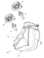
図1は本発明に係る自動二輪車用前照灯の第1の実施の形態を示す斜視図であり、自動二輪車用前照灯1(以下「前照灯1」と記す。)は、ハウジング2と、このハウジング2に取付けたレンズ部材3と、ハウジング2内に収納する光源としての電球4,4と、この電球4,4の取付け部を後方から密封するラバーキャップ5,5とからなる。
レンズ部材3は、レンズとしての透過部3aを前面に備える。
【0009】
図2は本発明に係る自動二輪車用前照灯の断面図(第1の実施の形態)であり、前照灯1は、リフレクタ6,6(奥側は不図示)と、このリフレクタ6,6上部に取付けた導光部材としての導光プリズム7,7(奥側は不図示)と、この導光プリズム7,7の前方の透過部3aに設けた小プリズム部3bとを備える。
リフレクタ6は、複数の反射面で構成した多反射面6aを有するマルチリフレクタ形式のものである。
【0010】
導光プリズム7は、リフレクタ6とレンズ部材3の透過部3aとの中間位置で、且つリフレクタ6で反射した光を遮らない位置、即ち、図では多反射面6aより上方の位置に配置し、電球4から発した直接光を透過部3aへ導くものであり、電球4からの光が入射する入射部7aと、内部に入射した光が反射する反射面7bと、レンズ部材3の小プリズム部3bに向けた前面7cとを備える。
【0011】
入射部7aは複数の入射面を形成したものであり、ここでは、任意の入射面を7d,7e,7fとする。これらの入射面7d,7e,7fは、入射する光の角度に応じて入射角を変化させ、光が反射面7bにほぼ同一角度で進むようにしたものである。
【0012】
これらの入射面の数は、本実施の形態に限るものではなく、更に多くても差し支えない。
小プリズム部3bは、導光プリズム7からの光をコーナリング時にコーナー内側の所定の方向に向けるものである。
【0013】
図3は本発明に係る自動二輪車用前照灯のリフレクタ部の斜視図(第1の実施の形態)であり、リフレクタ6は、反射に寄与しない非反射面を備えた略半円板状の非反射部6b,6c,6d,6eと、非反射部6bに導光プリズム7を取付けるための断面L字形のプリズム保持部6f,6gとを備える。なお、6hは切欠き部である。
導光プリズム7は、リフレクタ6のプリズム保持部6f,6gに挿入する側面凸部7g,7g(奥側は不図示)を備える。
【0014】
本実施の形態では、導光プリズム7を非反射部6bに取付けたが、非反射部6c,6d,6eのいずれか1箇所に取付けてもよいし、これらの非反射部6b,6c,6d,6eの内の複数箇所に取付けてもよい。更に、導光プリズム7は、リフレクタ6に溶着したり、リフレクタ6と一体成形してもよい。
【0015】
以上に述べた導光プリズム7の作用を次に説明する。
図4は本発明に係る自動二輪車用前照灯の導光プリズムの作用を示す拡大側面図(第1の実施の形態)である。
電球4から発した光を便宜上L1,L2及びL3とする。
まず、光L1は、導光プリズム7の入射面7dから入射し、この入射面7dで屈折する。
【0016】
この後、光L1は、反射面7bで反射して前面7cを通過し、レンズ部材3の小プリズム部3bにほぼ水平に進む。
その後、光L1は、小プリズム部3bで屈折して、コーナリング時のコーナー内側の所定路面に至る。
【0017】
また、光L2及び光L3は、光L1と同様に、まず、導光プリズム7の入射面7e,7fから入射し、この入射面7e,7fで屈折し、この後、共に反射面7bで反射して前面7cを通過し、レンズ部材3の小プリズム部3bにほぼ水平に進み、その後、小プリズム部3bで屈折して、コーナリング時のコーナー内側の所定路面に至る。
【0018】
以上のように、リフレクタ6(図2参照)と透過部3aとの中間位置で、且つリフレクタ6で反射した光を遮らない位置に、電球4からの直接光を透過部3aに導くための導光プリズム7を配置し、この導光プリズム7で集めた光を透過部3aを介して所定の方向に配光するので、導光プリズム7だけで光を集めることができ、構造が簡単になって、構成部品の増加を抑えることができる。
従って、前照灯1(図2参照)に要するコストを抑えることができる。
【0019】
また、従来、使われていなかった光を導光プリズム7で集めるので、電球4からの光を有効に利用することができるとともに、リフレクタ6に反射した光を導光プリズム7で遮らないので、自動二輪車の直進時の配光に影響を与えることなく、コーナリング時に必要な所定の配光を得ることができる。
【0020】
更に、導光プリズム7の入射面7d,7e,7f及び反射面7b及び前面7cの角度を異ならせたものに交換すれば、光を任意の角度でレンズ部材3の小プリズム部3bに入射させることができ、コーナリング時の配光を容易に変更することができる。
【0021】
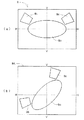
図5(a),(b)は本発明に係る自動二輪車用前照灯の第1の実施の形態のすれ違いビームにおけるスクリーン配光を示す図であり、(a)は直進時、(b)はコーナリング時の状態を示す。
(a)において、前照灯1(図1参照)のスクリーン配光8は、H線より下で且つ主光軸を含む主配光領域8aと、H線より上で且つV線の両側に配置した高光度領域8b,8cと、これら主配光領域8a、高光度領域8b,8c間に形成した低光度領域8dとからなる。
【0022】
(b)において、自動二輪車が、例えば左コーナーをコーナリング中には、自動二輪車の車体を左側に傾ける。これに伴い、前照灯1(図1参照)も傾く。この時、スクリーン配光8Aの高光度領域8bは、H線より下に移動する。この高光度領域8bは、前述したコーナリング時の所定の配光であり、コーナーの路肩やこの路肩の先の路面に対応する。また、右コーナーでは、高光度領域8cが所定の配光となる。
【0023】
図6は本発明に係る自動二輪車用前照灯の第1の実施の形態の走行ビームにおけるスクリーン配光を示す図であり、(a)は直進時、(b)はコーナリング時の状態を示す。
(a)において、前照灯1(図1参照)のスクリーン配光9は、H線上に長軸を有し、且つV線上に短軸を有する楕円形状の主配光領域9aと、この主配光領域9aの左右端上方に配置した高光度領域9b,9cとからなる。
【0024】
(b)において、自動二輪車が、例えば左コーナーをコーナリング中には、自動二輪車の車体を左側に傾ける。これに伴い、前照灯1(図1参照)も傾く。この時、スクリーン配光9Aの高光度領域9bは、H線より下に移動する。この高光度領域9bは、前述したコーナリング時の所定の配光であり、コーナーの路肩やこの路肩の先の路面に対応する。また、右コーナーでは、高光度領域9cが所定の配光となる。
【0025】
図7は本発明に係る自動二輪車用前照灯の第2の実施の形態を示す断面図であり、第1の実施の形態と同一構成については同一符号を付け、説明を省略する。
前照灯10は、リフレクタ11の上部に電球4からの光をレンズ部材3の透過部3aに導く導光部材としての複数本の光ファイバー12(奥側は不図示)を備える。
リフレクタ11は、多反射面6aと非反射部11aとを備える。
【0026】
非反射部11aは、光ファイバー12の一端部12aに電球4からの光を当てるための開口部11bと、光ファイバー12を保持するための光ファイバー保持部11c,11cとを有する。
光ファイバー12の最も下位である一端部12aは、リフレクタ11の多反射面6aよりも上方に位置し、多反射面6aで反射してレンズ部材3の透過部3aに向かう光を遮らない。
従って、自動二輪車の直進時の配光に影響を与えることがなく、また、従来使われていなかった光を光ファイバー12で有効に利用することができる。
【0027】
以上に述べた前照灯10の作用を次に説明する。
電球4から発した光は、矢印で示すように、光ファイバー12の一端部12aから光ファイバー12内に進み、他端部12bから出てほぼ水平にレンズ部材3に向かう。
この後、光は、矢印で示すように、レンズ部材3の小プリズム部3bで屈折して所定の方向に至る。
【0028】
柔軟な光ファイバー12を用いるので、上記したように非反射部11aに光ファイバー12を添わせる構成に限らず、光ファイバー12の他端部12bを自由に配置することができる。
これにより、レンズ部材3の透過部3aに導く光の方向を自由に設定することができ、コーナリング時に必要な所定の配光を容易に得ることができる。
【0029】
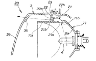
図8は本発明に係る自動二輪車用前照灯の第3の実施の形態を示す断面図であり、第1、第2の実施の形態と同一構成については同一符号を付け、説明を省略する。
前照灯20は、リフレクタ11の上部に電球4からの光を集める複数本の光ファイバー21及びこれらの光ファイバー21のレンズ部材3側に設けたプリズム部材22を備える。
上記光ファイバー21とプリズム部材22とで導光部材としての導光組立体23を構成する。
【0030】
プリズム部材22は、光ファイバー21で集めた光をレンズ部材3の小プリズム部3bに向けるもので、リフレクタ11の非反射部11aに接着又は溶着したものであり、光ファイバー21から出た光を屈折させる前面22aを有する。なお、22bは光ファイバー21を保持する光ファイバー保持部である。
【0031】
光ファイバー21の最も下位である一端部21aは、リフレクタ11の多反射面6aよりも上方に位置し、多反射面6aで反射してレンズ部材3の透過部3aに向かう光を遮らない。
従って、自動二輪車の直進時の配光に影響を与えることがなく、また、従来使われていなかった光を導光組立体23で有効に利用することができる。
【0032】
以上に述べた前照灯20の作用を次に説明する。
電球4から発した光は、光ファイバー21の一端部21aから光ファイバー21内に進み、他端部21bから出てプリズム部材22内を通過し、プリズム部材22の前面22aで屈折して透過部3aに向かい、レンズ部材3の小プリズム部3bで屈折して所定の方向に至る。
【0033】
プリズム部材22を用いるので、プリズム部材22によって透過部3aに向かう光の方向を自由に設定することができ、小プリズム部3bと組合わせることによって、配光の自由度を増すことができる。
以上のように、導光プリズム7(図2参照)、光ファイバー12(図7参照)及び導光組立体23をそれぞれ前照灯1,10,20内に収納したので、外観性を損なうことがない。
【0034】
尚、本発明では、プリズム、光ファイバーを導光部材としたが、本来のリフレクタの反射面を外方に延長し、この延長部を導光部材としてもよい。
また、本来のリフレクタとは別に第2のリフレクタを設け、この第2のリフレクタを導光部材としてもよい。
【0035】
更に、本発明では、導光部材で集めた光をレンズ部材3の小プリズム部3bにほぼ水平に向け、小プリズム部3bで必要な場所へ配光したが、これに限らず、レンズ部材3に小プリズム部3bを設けずに、導光部材で集めた光を透過部3aを介して直接必要な場所へ配光してもよい。
【0036】
【発明の効果】
本発明は上記構成により次の効果を発揮する。
請求項1の自動二輪車用前照灯は、自動二輪車用前照灯に、左右一対のリフレクタとレンズとの中間位置で、且つリフレクタで反射した光を遮らないリフレクタの多反射面より上方位置に、左右一対の光源からの直接光をレンズに導くための導光部材をそれぞれ配置し、これら左右一対の導光部材で集めた光をレンズのプリズム部を介して各所定の方向に配光し、導光部材を、複数の入射面を有する入射部と、この入射部から入射した光を反射させる反射面とから構成し、複数の入射面を、入射した光が反射面にほぼ同一角度で進むように設定したので、導光部材だけで光を集めるため、構造を簡単にすることができる。
【0037】
また、従来、使われていなかった光を導光部材で集めるので、光源からの光を有効に利用することができるとともに、リフレクタに反射した光を導光部材で遮らないので、自動二輪車の直進時の配光に影響を与えることなく、コーナリング時に必要な所定の配光を得ることができる。
【0038】
請求項2の自動二輪車用前照灯は、導光部材を、プリズムとしたので、単品で、且つ安価に導光部材を構成することができる。
従って、前照灯に要するコストを抑えることができる。
【図面の簡単な説明】
【図1】 本発明に係る自動二輪車用前照灯の第1の実施の形態を示す斜視図
【図2】 本発明に係る自動二輪車用前照灯の断面図(第1の実施の形態)
【図3】 本発明に係る自動二輪車用前照灯のリフレクタ部の斜視図(第1の実施の形態)
【図4】 本発明に係る自動二輪車用前照灯の導光プリズムの作用を示す拡大側面図(第1の実施の形態)
【図5】 本発明に係る自動二輪車用前照灯の第1の実施の形態のすれ違いビームにおけるスクリーン配光を示す図
【図6】 本発明に係る自動二輪車用前照灯の第1の実施の形態の走行ビームにおけるスクリーン配光を示す図
【図7】 本発明に係る自動二輪車用前照灯の第2の実施の形態を示す断面図
【図8】 本発明に係る自動二輪車用前照灯の第3の実施の形態を示す断面図
【符号の説明】
1,10,20…自動二輪車用前照灯、3a…レンズ(透過部)、3b…プリズム部(小プリズム部)、4…光源(電球)、6…リフレクタ、6a…多反射面、7,12,23…導光部材(導光プリズム、光ファイバー、導光組立体)、7a…入射部、7b…反射面、7d,7e,7f…入射面。[0001]
BACKGROUND OF THE INVENTION
The present invention relates to a motorcycle headlamp.
[0002]
[Prior art]
As a motorcycle headlamp, for example, Japanese Patent Application Laid-Open No. Sho 63-31280 “Headlamp for Motorcycle” is known.
In the above technique, a lens and a reflecting mirror are made movable so that a road surface light distribution pattern required in the traveling direction can be obtained even when the motorcycle body is inclined by a curve or the like. As shown, the fixed lens 2, the rotationally
[0003]
[Problems to be solved by the invention]
In the above-described technology, the rotationally
[0004]
In addition, in order to control the
In addition, since a part of the reflecting mirrors are the front and rear movable reflecting mirrors 5A and 5B, when the front and rear movable reflecting mirrors 5A and 5B and the rotary
An object of the present invention is to provide a motorcycle headlamp that has a simple structure, does not require advanced technology, and does not affect the light distribution when a motorcycle is traveling straight in order to obtain the above-mentioned screen light distribution. There is to do.
[0005]
[Means for Solving the Problems]
Claims of the present invention in order to achieve the above object 1 is the headlight for a motorcycle for obtaining light distribution required by guiding the light emitted from the light source into the lens through the reflector, before a motorcycle headlight In addition, a light guide member for guiding the direct light from the pair of left and right light sources to the lens at an intermediate position between the pair of left and right reflectors and the lens and above the multi-reflection surface of the reflector that does not block the light reflected by the reflector. each arranged to direct light collected by these pair of light guide members through the prism portion of the lens to the predetermined direction, the light guide member, and the entrance portion having a plurality of incident surfaces, The reflecting surface that reflects the light incident from the incident portion is configured, and the plurality of incident surfaces are set so that the incident light travels at substantially the same angle to the reflecting surface.
[0006]
Since the light is collected only by the light guide member, the structure is simplified.
Further, conventionally, since use is collecting light was not in the light guide member, together with the light can be effectively utilized from the light source, does not block the light reflected by the reflector in the light guide member, the motorcycle straight A predetermined light distribution necessary for cornering can be obtained without affecting the light distribution at the time .
[0007]
The light guide member may be a prism.
The light guide member can be configured as a single item at low cost.
[0008]
DETAILED DESCRIPTION OF THE INVENTION
Embodiments of the present invention will be described below with reference to the accompanying drawings. The drawings are viewed in the direction of the reference numerals.
FIG. 1 is a perspective view showing a first embodiment of a motorcycle headlamp according to the present invention. A motorcycle headlamp 1 (hereinafter referred to as “headlamp 1”) is a housing 2. And a
The
[0009]
FIG. 2 is a cross-sectional view (first embodiment) of a motorcycle headlamp according to the present invention. The headlamp 1 includes reflectors 6 and 6 (the rear side is not shown) and the reflectors 6 and 6. 6 includes
The reflector 6 is of a multi-reflector type having a
[0010]
The
[0011]
The
[0012]
The number of these incident surfaces is not limited to the present embodiment, and may be larger.
The
[0013]
FIG. 3 is a perspective view (first embodiment) of the reflector portion of the motorcycle headlamp according to the present invention. The reflector 6 has a substantially semicircular disk shape having a non-reflective surface that does not contribute to reflection. Non-reflective
The
[0014]
In the present embodiment, the
[0015]
Next, the operation of the
FIG. 4 is an enlarged side view (first embodiment) showing the operation of the light guide prism of the motorcycle headlamp according to the present invention.
For convenience, the light emitted from the light bulb 4 is denoted by L1, L2, and L3.
First, the light L1 enters from the
[0016]
Thereafter, the light L1 is reflected by the reflecting
Thereafter, the light L1 is refracted by the
[0017]
Similarly to the light L1, the light L2 and the light L3 are first incident from the incident surfaces 7e and 7f of the
[0018]
As described above, in order to guide the direct light from the light bulb 4 to the transmitting
Therefore, the cost required for the headlamp 1 (see FIG. 2) can be suppressed.
[0019]
In addition, since the light that has not been used in the past is collected by the
[0020]
Furthermore, if the
[0021]
FIGS. 5 (a) and 5 (b) are diagrams showing screen light distribution in a passing beam of the first embodiment of the motorcycle headlamp according to the present invention. Indicates the state during cornering.
In (a), the screen
[0022]
In (b), for example, when the motorcycle is cornering the left corner, the motorcycle body is tilted to the left. Along with this, the headlamp 1 (see FIG. 1) also tilts. At this time, the high
[0023]
FIGS. 6A and 6B are diagrams showing screen light distribution in the traveling beam of the motorcycle headlamp according to the first embodiment of the present invention, where FIG. 6A shows a straight traveling state and FIG. 6B shows a cornering state. .
In (a), the screen
[0024]
In (b), for example, when the motorcycle is cornering the left corner, the motorcycle body is tilted to the left. Along with this, the headlamp 1 (see FIG. 1) also tilts. At this time, the high
[0025]
FIG. 7 is a cross-sectional view showing a second embodiment of a motorcycle headlamp according to the present invention. The same components as those of the first embodiment are denoted by the same reference numerals, and description thereof is omitted.
The
The
[0026]
The
The
Therefore, the light distribution when the motorcycle is traveling straight is not affected, and light that has not been used in the past can be effectively used by the
[0027]
Next, the operation of the
The light emitted from the light bulb 4 travels from one
Thereafter, the light is refracted by the
[0028]
Since the flexible
Thereby, the direction of the light guided to the
[0029]
FIG. 8 is a cross-sectional view showing a third embodiment of a motorcycle headlamp according to the present invention. The same components as those in the first and second embodiments are denoted by the same reference numerals and description thereof is omitted. .
The
The
[0030]
The
[0031]
The
Therefore, the light distribution when the motorcycle is traveling straight is not affected, and light that has not been used conventionally can be used effectively by the
[0032]
Next, the operation of the
Light emitted from the light bulb 4 travels from one
[0033]
Since the
As described above, since the light guide prism 7 (see FIG. 2), the optical fiber 12 (see FIG. 7), and the
[0034]
In the present invention, the prism and the optical fiber are used as the light guide member. However, the reflection surface of the original reflector may be extended outward, and this extension may be used as the light guide member.
Further, a second reflector may be provided separately from the original reflector, and the second reflector may be used as the light guide member.
[0035]
Furthermore, in the present invention, the light collected by the light guide member is directed almost horizontally to the
[0036]
【The invention's effect】
The present invention exhibits the following effects by the above configuration.
Headlamp motorcycle according to claim 1, before a motorcycle headlight, at an intermediate position between the pair of reflectors and lenses, and an upper position than the multi-reflecting surface of the reflector which does not block the light reflected by the reflector , distributing the light guide member for directly guiding the light to the lens from the pair of light sources each arranged, the light collected by these pair of light guide members through the prism portion of the lens to the predetermined direction The light guide member is composed of an incident part having a plurality of incident surfaces and a reflecting surface for reflecting the light incident from the incident part, and the incident light is substantially the same as the reflecting surface. Since it is set so as to proceed at an angle, the structure can be simplified because light is collected only by the light guide member.
[0037]
Further, conventionally, since use is collecting light was not in the light guide member, together with the light can be effectively utilized from the light source, does not block the light reflected by the reflector in the light guide member, the motorcycle straight A predetermined light distribution necessary for cornering can be obtained without affecting the light distribution at the time .
[0038]
In the motorcycle headlamp according to the second aspect of the present invention, since the light guide member is a prism, the light guide member can be configured as a single product at low cost.
Therefore, the cost required for the headlamp can be suppressed.
[Brief description of the drawings]
FIG. 1 is a perspective view showing a first embodiment of a motorcycle headlamp according to the present invention. FIG. 2 is a cross-sectional view of a motorcycle headlamp according to the present invention (first embodiment).
FIG. 3 is a perspective view of a reflector portion of a motorcycle headlamp according to the present invention (first embodiment).
FIG. 4 is an enlarged side view showing a function of a light guide prism of a motorcycle headlamp according to the present invention (first embodiment).
[5] The present invention first embodiment before a motorcycle headlight according to FIG. 6 the invention showing a screen light distribution of the low beam of the first embodiment before a motorcycle headlight according to the FIG. 7 is a cross-sectional view showing a second embodiment of a motorcycle headlamp according to the present invention. FIG. 8 is a cross-sectional view showing a motorcycle headlight according to the present invention. Sectional drawing which shows 3rd Embodiment of a lamp
DESCRIPTION OF
Claims (2)
前記自動二輪車用前照灯は、左右一対の前記リフレクタと前記レンズとの中間位置で、且つリフレクタで反射した光を遮らない前記リフレクタの多反射面より上方位置に、左右一対の前記光源からの直接光をレンズに導くための導光部材をそれぞれ配置し、これら左右一対の導光部材で集めた光をレンズのプリズム部を介して各所定の方向に配光し、
前記導光部材は、複数の入射面を有する入射部と、この入射部から入射した光を反射させる反射面とからなり、
前記複数の入射面は、入射した光が前記反射面にほぼ同一角度で進むように設定されていることを特徴とした自動二輪車用前照灯。In a motorcycle headlamp that obtains the necessary light distribution by guiding the light emitted from the light source to the lens through the reflector,
The motorcycle headlamp is positioned between the pair of left and right light sources at a position intermediate between the pair of left and right reflectors and the lens and above the multi-reflecting surface of the reflector that does not block the light reflected by the reflector . direct light guide member for guiding light to the lens arranged to direct light collected by these pair of light guide members through the prism portion of the lens to the predetermined direction,
The light guide member includes an incident portion having a plurality of incident surfaces, and a reflecting surface that reflects light incident from the incident portion,
The motorcycle headlamp is characterized in that the plurality of incident surfaces are set such that incident light travels at substantially the same angle as the reflecting surface.
Priority Applications (1)
| Application Number | Priority Date | Filing Date | Title |
|---|---|---|---|
| JP16540198A JP4070880B2 (en) | 1998-06-12 | 1998-06-12 | Motorcycle headlights |
Applications Claiming Priority (1)
| Application Number | Priority Date | Filing Date | Title |
|---|---|---|---|
| JP16540198A JP4070880B2 (en) | 1998-06-12 | 1998-06-12 | Motorcycle headlights |
Publications (2)
| Publication Number | Publication Date |
|---|---|
| JP2000003607A JP2000003607A (en) | 2000-01-07 |
| JP4070880B2 true JP4070880B2 (en) | 2008-04-02 |
Family
ID=15811717
Family Applications (1)
| Application Number | Title | Priority Date | Filing Date |
|---|---|---|---|
| JP16540198A Expired - Fee Related JP4070880B2 (en) | 1998-06-12 | 1998-06-12 | Motorcycle headlights |
Country Status (1)
| Country | Link |
|---|---|
| JP (1) | JP4070880B2 (en) |
Cited By (1)
| Publication number | Priority date | Publication date | Assignee | Title |
|---|---|---|---|---|
| CN109070958A (en) * | 2016-03-30 | 2018-12-21 | 本田技研工业株式会社 | The front lamp device of saddle-ride type vehicle |
Families Citing this family (12)
| Publication number | Priority date | Publication date | Assignee | Title |
|---|---|---|---|---|
| JP4565603B2 (en) * | 2001-09-07 | 2010-10-20 | スタンレー電気株式会社 | Vehicle headlamp |
| CZ307329B6 (en) | 2006-05-15 | 2018-06-13 | Varroc Lighting Systems, s.r.o. | A lighting device for a motor vehicle, comprising a planar lightguide |
| JP4753310B2 (en) * | 2006-09-12 | 2011-08-24 | 本田技研工業株式会社 | Motorcycle lighting equipment |
| DE102009033062A1 (en) * | 2009-07-03 | 2011-01-05 | Volkswagen Ag | Headlamp system with light extraction function |
| JP2012198989A (en) * | 2009-08-04 | 2012-10-18 | Yamaha Motor Co Ltd | Two-wheeled motor vehicle |
| FR2960939B1 (en) * | 2010-06-08 | 2012-07-27 | Peugeot Citroen Automobiles Sa | LIGHT-GUIDING LIGHTING DEVICE SUPPLIED IN PART BY LIGHT LEVELED AT ITS LIGHT REFLECTOR |
| DE102011116028A1 (en) * | 2011-10-17 | 2013-04-18 | Busch & Müller KG | Headlight for bicycle, has prismatic lens which is provided for deflecting the light in the area of the radiation angle with respect to beam direction of the headlight |
| CN103398329B (en) * | 2013-08-08 | 2015-11-18 | 广东恒润光电有限公司 | Shot-light |
| GB2535758B (en) * | 2015-02-26 | 2018-09-05 | Bentley Motors Ltd | Vehicle light assembly and lighting method |
| JP6192238B2 (en) * | 2015-09-30 | 2017-09-06 | 本田技研工業株式会社 | Motorcycle |
| US10838137B2 (en) | 2017-08-29 | 2020-11-17 | Varroc Lighting Systems, s.r.o. | Lighting device with high efficiency and uniformity |
| CN113701122B (en) * | 2021-08-16 | 2023-06-02 | 重庆长安新能源汽车科技有限公司 | Sealing structure of automobile front combined lamp |
-
1998
- 1998-06-12 JP JP16540198A patent/JP4070880B2/en not_active Expired - Fee Related
Cited By (3)
| Publication number | Priority date | Publication date | Assignee | Title |
|---|---|---|---|---|
| CN109070958A (en) * | 2016-03-30 | 2018-12-21 | 本田技研工业株式会社 | The front lamp device of saddle-ride type vehicle |
| EP3437967A4 (en) * | 2016-03-30 | 2019-11-13 | Honda Motor Co., Ltd. | Headlight device for saddle-type vehicle |
| US10627068B2 (en) | 2016-03-30 | 2020-04-21 | Honda Motor Co., Ltd. | Headlight device for saddled vehicle |
Also Published As
| Publication number | Publication date |
|---|---|
| JP2000003607A (en) | 2000-01-07 |
Similar Documents
| Publication | Publication Date | Title |
|---|---|---|
| US6260991B1 (en) | Compact illuminator for distributed lighting system | |
| JP4070880B2 (en) | Motorcycle headlights | |
| US20080112180A1 (en) | Lighting unit | |
| US20020093827A1 (en) | Vehicle headlamp | |
| JP2006253137A (en) | Automobile headlight having plurality of function | |
| JP2003151318A (en) | Elliptical headlamp with subsidiary optical system | |
| JP2005251435A (en) | Vehicular headlight | |
| JPH07312103A (en) | Lighting fixture device | |
| JPH0366762B2 (en) | ||
| KR20220021168A (en) | Lamp for vehicle | |
| KR20060087415A (en) | Headlight for vehicle | |
| JPH07169305A (en) | Lighting fixture for vehicle | |
| JP4999671B2 (en) | Vehicle lighting | |
| US20060209556A1 (en) | Vehicle lamp | |
| KR100386221B1 (en) | Head lamp | |
| JPH0778503A (en) | Headlamp for automobile | |
| US6971778B2 (en) | Headlight for Vehicles | |
| JP4459095B2 (en) | Bending lamp for vehicles | |
| JP7268339B2 (en) | Vehicle light guide, light source unit, and vehicle headlamp | |
| JPS5947841B2 (en) | Vehicle lights | |
| JP2021111446A (en) | Vehicular lighting fixture | |
| JP4222145B2 (en) | VEHICLE LIGHT AND METHOD FOR PRODUCING VEHICLE LIGHT | |
| JP2000299005A (en) | Vehicle lighting fixture | |
| JPH01159904A (en) | Projector type head light | |
| JPH01159901A (en) | Automobile head light |
Legal Events
| Date | Code | Title | Description |
|---|---|---|---|
| A621 | Written request for application examination |
Free format text: JAPANESE INTERMEDIATE CODE: A621 Effective date: 20041202 |
|
| A131 | Notification of reasons for refusal |
Free format text: JAPANESE INTERMEDIATE CODE: A131 Effective date: 20070717 |
|
| A521 | Written amendment |
Free format text: JAPANESE INTERMEDIATE CODE: A523 Effective date: 20070913 |
|
| A02 | Decision of refusal |
Free format text: JAPANESE INTERMEDIATE CODE: A02 Effective date: 20071016 |
|
| A521 | Written amendment |
Free format text: JAPANESE INTERMEDIATE CODE: A523 Effective date: 20071115 |
|
| A911 | Transfer to examiner for re-examination before appeal (zenchi) |
Free format text: JAPANESE INTERMEDIATE CODE: A911 Effective date: 20071220 |
|
| TRDD | Decision of grant or rejection written | ||
| A01 | Written decision to grant a patent or to grant a registration (utility model) |
Free format text: JAPANESE INTERMEDIATE CODE: A01 Effective date: 20080115 |
|
| A61 | First payment of annual fees (during grant procedure) |
Free format text: JAPANESE INTERMEDIATE CODE: A61 Effective date: 20080116 |
|
| R150 | Certificate of patent or registration of utility model |
Free format text: JAPANESE INTERMEDIATE CODE: R150 |
|
| FPAY | Renewal fee payment (event date is renewal date of database) |
Free format text: PAYMENT UNTIL: 20110125 Year of fee payment: 3 |
|
| FPAY | Renewal fee payment (event date is renewal date of database) |
Free format text: PAYMENT UNTIL: 20110125 Year of fee payment: 3 |
|
| FPAY | Renewal fee payment (event date is renewal date of database) |
Free format text: PAYMENT UNTIL: 20120125 Year of fee payment: 4 |
|
| FPAY | Renewal fee payment (event date is renewal date of database) |
Free format text: PAYMENT UNTIL: 20130125 Year of fee payment: 5 |
|
| FPAY | Renewal fee payment (event date is renewal date of database) |
Free format text: PAYMENT UNTIL: 20130125 Year of fee payment: 5 |
|
| FPAY | Renewal fee payment (event date is renewal date of database) |
Free format text: PAYMENT UNTIL: 20140125 Year of fee payment: 6 |
|
| LAPS | Cancellation because of no payment of annual fees |