JP4070499B2 - Operation method of Stirling cooling device and Stirling refrigerator using the same - Google Patents
Operation method of Stirling cooling device and Stirling refrigerator using the same Download PDFInfo
- Publication number
- JP4070499B2 JP4070499B2 JP2002117045A JP2002117045A JP4070499B2 JP 4070499 B2 JP4070499 B2 JP 4070499B2 JP 2002117045 A JP2002117045 A JP 2002117045A JP 2002117045 A JP2002117045 A JP 2002117045A JP 4070499 B2 JP4070499 B2 JP 4070499B2
- Authority
- JP
- Japan
- Prior art keywords
- stirling
- heat exchange
- temperature side
- temperature
- side heat
- Prior art date
- Legal status (The legal status is an assumption and is not a legal conclusion. Google has not performed a legal analysis and makes no representation as to the accuracy of the status listed.)
- Expired - Fee Related
Links
Images


Classifications
-
- F—MECHANICAL ENGINEERING; LIGHTING; HEATING; WEAPONS; BLASTING
- F25—REFRIGERATION OR COOLING; COMBINED HEATING AND REFRIGERATION SYSTEMS; HEAT PUMP SYSTEMS; MANUFACTURE OR STORAGE OF ICE; LIQUEFACTION SOLIDIFICATION OF GASES
- F25B—REFRIGERATION MACHINES, PLANTS OR SYSTEMS; COMBINED HEATING AND REFRIGERATION SYSTEMS; HEAT PUMP SYSTEMS
- F25B9/00—Compression machines, plants or systems, in which the refrigerant is air or other gas of low boiling point
- F25B9/14—Compression machines, plants or systems, in which the refrigerant is air or other gas of low boiling point characterised by the cycle used, e.g. Stirling cycle
-
- F—MECHANICAL ENGINEERING; LIGHTING; HEATING; WEAPONS; BLASTING
- F25—REFRIGERATION OR COOLING; COMBINED HEATING AND REFRIGERATION SYSTEMS; HEAT PUMP SYSTEMS; MANUFACTURE OR STORAGE OF ICE; LIQUEFACTION SOLIDIFICATION OF GASES
- F25D—REFRIGERATORS; COLD ROOMS; ICE-BOXES; COOLING OR FREEZING APPARATUS NOT OTHERWISE PROVIDED FOR
- F25D17/00—Arrangements for circulating cooling fluids; Arrangements for circulating gas, e.g. air, within refrigerated spaces
- F25D17/04—Arrangements for circulating cooling fluids; Arrangements for circulating gas, e.g. air, within refrigerated spaces for circulating air, e.g. by convection
- F25D17/06—Arrangements for circulating cooling fluids; Arrangements for circulating gas, e.g. air, within refrigerated spaces for circulating air, e.g. by convection by forced circulation
-
- F—MECHANICAL ENGINEERING; LIGHTING; HEATING; WEAPONS; BLASTING
- F25—REFRIGERATION OR COOLING; COMBINED HEATING AND REFRIGERATION SYSTEMS; HEAT PUMP SYSTEMS; MANUFACTURE OR STORAGE OF ICE; LIQUEFACTION SOLIDIFICATION OF GASES
- F25B—REFRIGERATION MACHINES, PLANTS OR SYSTEMS; COMBINED HEATING AND REFRIGERATION SYSTEMS; HEAT PUMP SYSTEMS
- F25B2309/00—Gas cycle refrigeration machines
- F25B2309/001—Gas cycle refrigeration machines with a linear configuration or a linear motor
Description
【0001】
【発明の属する技術分野】
本発明は、フリーピストン型のスターリング冷凍機を備えたスターリング冷却装置における運転方法及びその運転方法により運転するスターリング冷蔵庫に関するものである。
【0002】
【従来の技術】
一般に、家庭用冷凍冷蔵庫に用いられる冷凍サイクルは圧縮機を備え、主としてフロンや代替フロンを利用する蒸気圧縮式冷凍サイクルである。しかし、これらの冷媒はオゾン層破壊や地球温暖化の原因となるため、地球環境への配慮から全世界的にその使用が規制されている。
【0003】
そこで、蒸気圧縮式冷凍サイクルに代わる技術として、逆スターリングサイクルを用いた冷凍装置であるスターリング冷凍機およびこれを用いたスターリング冷蔵庫の研究開発が進められている。このスターリング冷凍機は、作動媒体にヘリウムや窒素などの不活性ガスを用いるため地球環境に悪影響を及ぼすことがない。
【0004】
こういった逆スターリングサイクルを利用し冷熱を得るスターリング冷凍機として、構造的に異なるいくつかの方式が既に考案されているが、中でもフリーピストン型と呼ばれる方式は、機械損失が少なく小型軽量であることで知られている。
【0005】
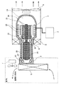
図12は、フリーピストン型スターリング冷凍機を用いたスターリング冷却装置の側断面図である。スターリング冷凍機1は密閉されており、内部には冷媒が充填されている。冷媒にはヘリウムガスや窒素ガスなどが用いられる。ここに示すように膨張空間22と圧縮空間23を仕切るディスプレーサ20と、リニアモータ25に接続され、特定の周期で冷媒に対し圧縮、膨張といった機械仕事を行うピストン21とが互いに位相差をもって往復動作する。そして、このピストン21とディスプレーサ20の往復動により冷媒が膨張空間22と圧縮空間23を行き来し、膨張空間22と圧縮空間23の間に設けられた再生器26に対して吸熱または放熱する。それにより、膨張空間22で低温、圧縮空間23で高温を得ることができる。
【0006】
また、膨張空間22には低温側内部熱交換器27が設けられ、これを通じてコールドヘッド3より冷熱が得られる。一方、圧縮空間23には高温側内部熱交換器28が設けられ、これを通じてウォームヘッド4より放熱を行う。さらに、上述のディスプレーサ20はモータやクランク等の直接位相制御される機構を持たない。ディスプレーサ20に接続されピストン21を貫通するよう設けられたディスプレーサーロッド29が、ピストン21の動作によるバウンス空間24の圧力変動の影響を受けることにより、ディスプレーサ20がピストン21に対し所定の位相差で動作するよう設計される。
【0007】
また、コールドヘッド3に接続される低温側熱交換器5は、庫内ファン7により送風される空気を冷却し、冷却対象となる庫内を冷却する。また、ウォームヘッド4に接続される高温側熱交換器6は、庫外ファン8により送風される空気を放熱する。一方、制御基板2によりリニアモータ25への入力電圧を操作してピストン21の振幅を制御し冷凍能力を調整するとともに、ディスプレーサ20の脱調防止や、ディスプレーサ20とピストン21が衝突しないよう運転される。
【0008】
このように、フリーピストン式スターリング冷凍機1は、ディスプレーサ20に対して直接駆動する機構をもたないことにより、機械損失の少ない高効率な冷凍装置を実現する。また。このフリーピストン式スターリング冷凍機1を利用することにより、オゾン層破壊や地球温暖化につながる冷媒を用いない、高効率なスターリング冷蔵庫を得ることができる。
【0009】
【発明が解決しようとする課題】
ディスプレーサ20とピストン21の位相差はバウンス空間24の圧力変動によって決まるが、実際には膨張空間22と圧縮空間23の圧力バランス(または温度バランス)やバウンス空間24そのもの圧力状態(または温度状態)の影響を受ける。特に膨張空間22と圧縮空間24に温度差がほとんどなく、バウンス空間24の温度が上がりきっていない状態ではディスプレーサ20の振幅および位相が不安定なため、効率が低下するばかりでなく、ディスプレーサ20が脱調するなどして、ディスプレーサ20とピストン21とが衝突する危険性がある。
【0010】
このため、ピストン21の振幅を大きくすることができず、結果としてその間、低い冷凍能力しか得られない。さらに、冷凍能力が低いため、膨張空間22、圧縮空間23、バウンス空間24の圧力バランス(または温度バランス)が長時間改善されない。
【0011】
このような不安定状態は、スターリング冷凍機1の始動時や、一定時間停止した後の再始動時に起こる。実用上、特に問題と考えられるのは、コールドヘッド3に接続された低温側熱交換器5の表面に付着した霜を融解し排水する除霜処理の間、スターリング冷凍機は停止、又はモータへの入力を低く押さえた停止に準じた状態となるので、除霜処理終了後、再冷却開始直後に高い冷凍能力が得られず、結果として冷却対象となる冷凍室などの温度上昇を招き、庫内の食品に悪影響を与える。
【0012】
そこで本発明は、不安定状態を抜け出し、速やかに高い冷凍能力が得られるフリーピストン型のスターリング冷凍機を用いたスターリング冷却装置の運転方法を提供することを目的とする。また、その運転方法を用いたスターリング冷蔵庫を提供することを目的とする。
【0013】
【課題を解決するための手段】
上記目的を達成するために本発明では、スターリング冷凍機のコールドヘッドまたはウォームヘッドの温度が不安定状態を脱する温度になるまで、スターリング冷凍機にかかる負荷を最小にするようにした。
【0014】
第1の発明は、フリーピストン型のスターリング冷凍機と、該スターリング冷凍機のコールドヘッドの温度を測定する第1の温度測定手段と、前記スターリング冷凍機のウォームヘッドの温度を測定する第2の温度測定手段と、前記コールドヘッドで発生する冷熱を熱交換する低温側熱交換手段と、前記ウォームヘッドで発生する温熱を熱交換する高温側熱交換手段と、前記低温側熱交換手段又は高温側熱交換手段での熱交換を促進する熱交換促進手段と、前記第1及び第2の温度測定手段の測定結果に基づき前記熱交換促進手段を制御する制御手段と、を備えたスターリング冷却装置における運転方法であって、
前記コールドヘッドとウォームヘッドとの温度差が所定温度以下のときは不安定状態と判定し、前記熱交換促進手段を停止させて安定状態に移行させることを特徴とするものである。
【0015】
この構成によると、コールドヘッドとウォームヘッドとの温度差が所定温度以下のときは不安定状態と判定し、前記熱交換促進手段を停止させるので、コールドヘッド又は/及びウォームヘッドの温度が不安定状態を脱する温度状態になるまでは冷凍機に負荷をかけないように制御できる。また、所定温度の閾値による判定にスターリング冷凍機の周囲温度の高低による影響を受けにくく、環境条件に対して安定した制御ができるため、速やかに、安定動作する温度状態に達し高い冷凍能力を得ることができる状態になる。
【0016】
第2の発明は、前記熱交換促進手段はファンであり、前記低温側熱交換手段での熱交換を促進するための庫内ファンと、前記高温側熱交換手段での熱交換を促進するための庫外ファンとを含むと共に、これらのファンは前記制御手段により回転制御されることを特徴とするものである。
【0017】
この構成によると、ファンの停止中は低温側または高温側熱交換手段はわずかに自然対流で循環する空気に対して熱交換する状態になり、スターリング冷凍機に対する負荷を低く押さえることができる。さらに、ファンの回転数を制御することで、熱交換量を適度に調整することができるため、ファンの運転開始後すぐに冷凍機に過度の負荷がかかり、再び不安定状態に戻るのを防ぎ、安定して高い冷凍能力を得つづけることができる。
【0018】
第3の発明は、前記低温側熱交換手段又は高温側熱交換手段は、循環路を二次冷媒が強制循環する強制循環式熱交換器であり、前記熱交換促進手段は、前記循環路上に設けられた循環ポンプであり、該循環ポンプは前記制御手段により通電制御されることを特徴とするものである。
【0019】
この構成によると、循環ポンプを停止した状態では二次冷媒の循環がほぼ止まるため、二次冷媒から冷却や放熱の対象となる空気への熱交換が殆んど行われず、冷凍機にかかる負荷を最小にすることができる。
【0020】
第4の発明のスターリング冷蔵庫は、第1〜第3の発明の何れかのスターリング冷却装置の運転方法により運転することを特徴とするものである。
【0021】
この構成によると、除霜処理終了後の再冷却などを速やかに行うことができ、庫内の温度上昇による食品などへの悪影響をなくすることができる。
【0036】
【発明の実施の形態】
以下に本発明の実施形態について図面を参照して説明する。なお、本発明のスターリング冷凍機には図12に示した従来のスターリング冷凍機1を採用することができる。
【0037】
<第1の実施形態>
図1は、第1の実施形態のスターリング冷却装置の概略構成図である。スターリング冷凍機1は冷凍機制御基板2により特定周波数の電力供給を受け、入力電圧の大小によって冷凍能力を可変的に制御すると同時に、過度の電力供給を受けスターリング冷凍機1を破損することがないよう運転される。このスターリング冷凍機1のコールドヘッド3には低温側熱交換器5が接続される。低温側熱交換器5はスターリング冷凍機1より得られた冷熱と庫内の空気との熱交換を行う。庫内の空気の循環には庫内ファン7を用い、冷却対象である庫内へ送風する。
【0038】
一方、ウォームヘッド4には高温側熱交換器6が接続される。高温側熱交換器6は庫外ファン8より送風される空気と熱交換を行い、ウォームヘッド4を冷却する。コールドヘッド3の表面には、温度センサ9aが密着するよう取り付けられ、温度センサ9aによるコールドヘッド表面温度Tcの測定結果を示す出力信号は負荷制御基板10に伝達される。負荷制御基板10は庫内ファン7に接続されており、温度センサ9aによる温度測定結果に基づき庫内ファン7へ供給する電力の制御を行う。
【0039】
このとき、負荷制御基板10において行われる処理過程を図2のフローチャートを用いて説明する。まずステップS1において温度センサ9aにより測定されたコールドヘッド表面温度Tcを読み込み、ステップS2へ進んでコールドヘッド表面温度Tcが閾値Tt以下か否かを判定する。ステップS2においてTc>TtであればステップS4へ進んで庫内ファン7への通電をOFF(庫内ファン7の運転を停止)し、スターリング冷凍機1への負荷を減じる。一方、ステップS2においてTc≦TtであればステップS3へ進んで庫内ファン7への通電をON(庫内ファン7の運転を開始)し、スターリング冷凍機1へ負荷をかけ冷却対象となる庫内の冷却を行う。
【0040】
ここで用いられる閾値Ttは不安定状態を抜け出し安定状態にあると判断できる温度であり、実験により決定される。詳述すると、スターリング冷凍機1のディスプレーサがピストンやコールドヘッドと衝突せず、設計仕様どおりのピストン振幅が得られるときのコールドヘッド表面温度Tcを調べ、その近傍温度を閾値Ttとする。
【0041】
図3に、冷凍能力Qcとコールドヘッド表面温度Tcおよび閾値Ttの関係の一例を示す。図中、横軸はコールドヘッド表面温度Tc、縦軸は冷凍能力Qc、破線で示したQc設計曲線は上述のピストン振幅が設計どおりに得られた場合の推定値であり、実線で示したQc実効曲線は不安定状態などによりピストン振幅を減じたことによるQcの最大値である。閾値TtはQc設計曲線とQc実効曲線とが交わる近傍の温度とすることができる。
【0042】
上記の第1の実施形態ではコールドヘッド表面温度Tcの閾値Ttを一つとしているが、低温の閾値Tt1と高温の閾値Tt2を設け、Tc≦Tt1となったとき庫内ファン7への通電を開始し、庫内ファン通電後にTc≧Tt2となったとき庫内ファン7への通電を停止しても良い。この場合は、庫内ファン7の運転のハンチング抑制することができ、庫内ファン7の発停回数の増加を押さえ寿命を延ばすことができる。
【0043】
<第2の実施形態>
第2の実施形態として、図1において温度センサ9bをウォームヘッド4の表面に密着させウォームヘッド表面温度Thを測定してもよい。この場合、負荷制御基板10は庫外ファン8に接続されており、温度センサ9bの温度測定結果に基づき庫外ファン8へ供給される電力の制御を行う。
【0044】
このとき、負荷制御基板10において行われる処理過程を図4のフローチャートを用いて説明する。まずステップS11において温度センサ9bにより検知されたウォームヘッド表面温度Thを読み込み、ステップS12へ進んでウォームヘッド表面温度Thが閾値Tt以上か否かを判定する。ステップS12においてTh<TtであればステップS14へ進んで庫外ファン8への通電をOFF(庫外ファン8の運転を停止)し、スターリング冷凍機1にかかる負荷を減じる。
【0045】
一方、ステップS12においてTh≧TtであればステップS13へ進んで庫外ファン8への通電をON(庫外ファン8の運転を開始)し、ウォームヘッド4は高温側熱交換器6を介して放熱を行う。
【0046】
<第3の実施形態>
第3の実施形態として、図1においてコールドヘッド3の表面に密着させた温度センサ9aと、ウォームヘッド4の表面に密着させた温度センサ9bの両方を利用し、コールドヘッド表面温度Tcとウォームヘッド表面温度Thを測定してもよい。この場合、負荷制御基板10は庫内ファン7と庫外ファン8のどちらか一方又は両方に接続されており、これらの温度測定結果に基づき庫内ファン7と庫外ファン8へ供給する電力の制御を行う。
【0047】
このとき、負荷制御基板10において行われる処理過程の一例を図5のフローチャートを用いて説明する。まずステップS21において温度センサ9aおよび温度センサ9bにより検知されたコールドヘッド表面温度Tcとウォームヘッド表面温度Thを読み込み、ステップS22へ進んでTcとThの温度差が閾値Tt以上か否かを判定する。ステップS22において(Th−Tc)<TtであればステップS24へ進んで庫内ファン7および庫外ファン8への通電をOFF(庫内ファン7および庫外ファン8の運転を停止)し、スターリング冷凍機1にかかる負荷を減じる。
【0048】
一方、ステップS22において(Th−Tc)≧TtであればステップS23へ進んで庫内ファン7および庫外ファン8への通電をON(庫内ファン7および庫外ファン8の運転を開始)し、スターリング冷凍機1へ負荷をかけ、コールドヘッド3は低温側熱交換器5を介して冷却対象となる庫内の冷却を行うとともに、ウォームヘッド4は高温側熱交換器6を介して放熱を行う。この方法では、TcまたはThのどちらか一方を利用する場合に比べて環境温度の影響を受けにくく、環境温度の変化に対してより安定した冷凍能力が得られる冷却装置を提供することができる。なお、熱交換促進手段は、庫内ファン7と庫外ファン8の何れか一方であっても構わない。
【0049】
<第4の実施形態>
図6は、第4の実施形態のスターリング冷却装置の概略構成図である。なお、図6において図1と同じ構成部分については同じ符号を付して詳細な説明を省略する。図6において、冷凍機制御手段2よりスターリング冷凍機1に供給される電力を検知する供給電力検知手段11を設け、その検知結果を示す出力信号を負荷制御基板10に伝達する。負荷制御基板10は庫内ファン7および庫外ファン8の両方、又はどちらか一方に接続されており、供給電力検知手段11の検知結果に基づき庫内ファン7又は庫外ファン8へ供給する電力の制御を行う。ここで、電力検知手段11は直接的に入力電圧などを測定しても良いが、冷凍機制御手段2の制御パラメータを利用し、供給電力Eを類推しても良い。
【0050】
このとき、負荷制御基板10において行われる処理過程を図7に示す。まずステップS31において供給電力検知手段7により検知された供給電力Eを読み込み、ステップS32へ進んで供給電力Eが閾値Et以上か否かを判定する。ステップS32においてE<EtであればステップS34へ進んで庫内ファン7への通電をOFF(庫内ファン7の運転を停止)し、スターリング冷凍機1への負荷を減じる。
【0051】
一方、ステップS32においてE≧EtであればステップS33へ進んで庫内ファン7への通電をON(庫内ファン7の運転を開始)し、スターリング冷凍機1へ負荷をかけ冷却対象となる庫内の冷却を行う。この方法では、環境温度の変化に対してより安定した冷凍能力が得られる冷却装置を提供することができる。なお、熱交換促進手段は、庫内ファン7と庫外ファン8の何れか一方であっても構わない。
【0052】
<第5の実施形態>
第1〜第4の実施形態では、熱交換促進手段として庫内ファン7ないしは庫外ファン8を利用しその運転/停止を択一的に行っただけであるのに対し、第5の実施形態は運転中の回転数を可変的に変えるようにしたものであり、その構成は第1から第4の実施形態と同じである。よって図1と同じ構成として、図8を用いて処理過程を説明すると、ステップS41〜S44は図2に示した第1の実施形態のステップS1〜S4と同じであり、ステップS43に続いてステップS45に進む。ステップS45において、あらかじめ設定されたコールドヘッド表面温度Tcと庫内ファン7の必要風量の関係に基づいて、ステップS41で読み込んだTcに対応する風量を導き出し、その風量に応じて庫内ファン7の回転数を調整する。
【0053】
なお、第5の実施形態はコールドヘッド温度Tcを利用する第1の実施形態に準じたものとなっているが、ウォームヘッド温度Thを利用する第2、第3の実施形態や、スターリング冷凍機への供給電力を利用する第4の実施形態に準じたものであっても良い。
【0054】
<第6の実施形態>
第1〜第5の実施形態では、熱交換促進手段として庫内ファン7ないしは庫外ファン8を利用したが、第6の実施形態は低温側熱交換手段または高温側熱交換手段として、図9に示すような二次冷媒を用いた自然循環式熱交換器を備え、二次冷媒の循環路に熱交換促進手段として電磁弁を設けた構成である。
【0055】
低温側に用いられる自然循環式熱交換器12は、コールドヘッドに接続される凝縮器12aと庫内の空気を冷却する蒸発器12bを2本の循環路12cで連通させ密閉されている。その内部には二次冷媒として二酸化炭素などの炭酸ガスや、イソブタンなどの炭化水素が封入されている。凝縮器12aの内部においてコールドヘッドの冷熱で液化した二次冷媒は、重力により循環路12cのうち一方を流下して蒸発器12bに導かれる。蒸発器12bでは庫内空気を冷却することによって二次冷媒が蒸発し、気体となって他方の循環路12cを通って凝縮器12aに戻ることにより、二次冷媒が循環しコールドヘッドより蒸発器12bを介して庫内空気に冷熱が供給される。
【0056】
ただし、循環に重力を利用するため、凝縮器12aの下方に蒸発器12bが設置される。ここで循環路12cには電磁弁14aが設けられており、負荷制御手段により弁の開閉制御がなされ、電磁弁14aを開いた場合には前述のとおり二次冷媒が循環しコールドヘッドに負荷がかかるが、閉じた場合には循環がないため庫内空気への冷熱の供給が行われず、コールドヘッドに対する負荷を減じる。この電磁弁14aに対して行われる処理過程は、第1、第3、第4の実施形態で庫内ファン7に対してなされたものに準じるので、詳細な説明は省略する。
【0057】
また、高温側に用いられる自然循環式熱交換器13は、低温側とは利用される温度域や熱の移動方向が異なるため、炭化水素や水を二次冷媒として用い、蒸発器13bがウォームヘッド側に取り付けられ、凝縮器13aが庫外空気へ放熱する他は、二次冷媒の動作が上述の低温側と同様であり、電磁弁14bに対して行われる処理過程は、第2、第3、第4の実施形態で庫外ファン8に対してなされたものに準じるので、詳細な説明は省略する。
【0058】
<第7の実施形態>第7の実施形態は低温側熱交換手段または高温側熱交換手段として、図10に示すような二次冷媒を用いた強制循環式熱交換器を備え、熱交換促進手段として循環ポンプを利用する構成である。
【0059】
低温側に用いられる強制循環式熱交換器15は、コールドヘッドに接続されるコールドヘッド側熱交換器15aと庫内の空気を冷却する庫内気流側熱交換器15bを2本の循環路15cで連通させ、その内部には二次冷媒が封入されており、循環路15cに設けられた循環ポンプ15dの動力により二次冷媒が循環し、コールドヘッドの冷熱を庫内の気流へ伝達する構成となっている。二次冷媒は液体のみの液相状態で循環しても、液体と気体が混在する気液二相状態で循環してもよく、液相状態であればエタノールなどのアルコール、気液二相状態であれば炭化水素や炭酸ガスが二次冷媒として用いられる。
【0060】
ここで、循環ポンプ15dは、負荷制御手段により運転/停止の制御がなされ、循環ポンプ15dを運転した場合には上述のとおり二次冷媒が循環しコールドヘッドに負荷がかかるが、循環ポンプ15dを停止した場合には循環しないため庫内空気への冷熱の供給が行われず、コールドヘッドに対する負荷を減じる。この強制循環式熱交換器15に対して行われる処理過程は、第1、第3、第4、第5の実施形態で庫内ファン7に対してなされたものに準じるので、詳細な説明は省略する。
【0061】
また、同様に高温側に用いられる強制循環式熱交換器16は、温度帯が異なるため利用される二次冷媒が、液相のみであれば水やアルコール、エチレングリコールなどの不凍液であり、気液二相であれば同じく水や炭化水素である他は、上述の低温側と同様であり、循環ポンプ16dに対して行われる処理過程は、第2、第3、第4、第5の実施形態で庫外ファン8に対してなされたものに準じるので、詳細な説明は省略する。
【0062】
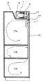
<第8の実施形態>
図11に、本発明のスターリング冷却装置を備えたスターリング冷蔵庫の側断面図を示す。スターリング冷蔵庫17は互いに断熱し仕切られた冷蔵室17a、野菜室17b、冷凍室17cを備えてなり、スターリング冷凍機1の冷熱は低温側熱交換器5により庫内空気に伝達され、庫内ファン7によりダクト18を通じて冷蔵室17a、野菜室17b、冷凍室17cに適切な割合で送風され、庫内の食品を冷却する。
【0063】
一方、庫内を循環する空気には食品から蒸発する水分などもあり、この空気中の水分が低温側熱交換器5の表面に霜となって付着し、熱交換性能を低下させるとともに、庫内ファン7による送風の妨げとなるため、必要に応じて低温側熱交換器5の除霜処理を行う。
【0064】
除霜処理では、まずスターリング冷凍機1を停止または電力供給を下げ停止に近い状態に保ち、冷熱を発生させないようにし、庫内ファン7も停止して除霜ヒータ19へ通電する。除霜ヒータ19にはガラス管ヒータなどが用いられ、低温側熱交換器5の表面に付着した霜を解かしてダクト18の外へ排水する。除霜処理は低温側熱交換器5の表面温度または周辺空気の温度が、0℃よりも十分高く霜が解けきったと判断できるまで続けられるため、通常20〜30分の時間を要する。そして、除霜終了後に上述の運転方法によって速やかに冷熱の供給がなされる。
【0065】
なお、上記の説明では除霜処理の終了後に本発明の運転方法を行うとしたが、スターリング冷蔵庫への通電開始直後や、冷蔵庫の扉を長時間開け放した後など、スターリング冷凍機が長時間停止状態にあり、速やかな冷熱の供給を要する場合に本発明の運転方法を適用しても良い。
【0066】
【発明の効果】
本発明のスターリング冷却装置の運転方法によると、コールドヘッド温度が不安定状態を脱する温度状態になるまでは冷凍機に負荷をかけないため、速やかに安定動作する温度状態に達し、高い冷凍能力を得ることができる状態になる。
【0067】
また本発明のスターリング冷却装置の運転方法によると、ウォームヘッド温度が不安定状態を脱する温度状態になるまでは冷凍機に負荷をかけないため、速やかに安定動作する温度状態に達し、高い冷凍能力を得ることができる状態になる。
【0068】
また本発明のスターリング冷却装置の運転方法によると、閾値による判定にスターリング冷凍機の周囲温度の高低による影響を受けにくく、環境条件に対して安定した制御ができるため、速やかに安定動作する温度状態に達し、高い冷凍能力を得ることができる状態になる。
【0069】
また本発明のスターリング冷却装置の運転方法によると、スターリング冷凍機への供給電力を知ることにより、スターリング冷凍機の運転条件に応じた適切な負荷を供給できるため、過負荷とならず安定した冷凍能力を得ることができる。
【0070】
また本発明のスターリング冷却装置の運転方法によると、ファンの停止中は低温側または高温側熱交換手段はわずかに自然対流で循環する空気に対して放熱する状態になり、スターリング冷凍機に対する負荷を低く押さえることができる。
【0071】
また本発明のスターリング冷却装置の運転方法によると、負荷を適度に調整することができるため、ファンの運転開始後すぐに冷凍機に過度の負荷がかかり、再び不安定状態に戻るのを防ぎ、安定して高い冷凍能力を得つづけることができる。
【0072】
また本発明のスターリング冷却装置の運転方法によると、電磁弁を閉じた状態では二次冷媒の循環が止まるため、二次冷媒から冷却や放熱の対象となる空気への熱交換が一切行われず、冷凍機にかかる負荷を最小にすることができる。
【0073】
また本発明のスターリング冷却装置の運転方法によると、循環ポンプを停止した状態では二次冷媒の循環がほぼ止まるため、二次冷媒から冷却や放熱の対象となる空気への熱交換が行われず、冷凍機にかかる負荷を最小にすることができる。
【0074】
また本発明のスターリング冷却装置の運転方法によると、負荷を適度に調整することができるため、循環ポンプの運転開始後すぐに冷凍機に過度の負荷がかかり、再び不安定状態に戻るのを防ぎ、安定して高い冷凍能力を得つづけることができる。
【0075】
また本発明のスターリング冷蔵庫によると、除霜処理終了後の再冷却などを速やかに行うことができ、庫内の温度上昇による食品などへの悪影響をなくすることができる。
【図面の簡単な説明】
【図1】 第1の実施形態のスターリング冷却装置の概略構成図である。
【図2】 第1の実施形態の負荷制御基板での処理過程を示すフローチャートである。
【図3】 第1の実施形態の冷凍能力とコールドヘッド表面温度および閾値の関係の一例を示す図である。
【図4】 第2の実施形態の負荷制御基板での処理過程を示すフローチャートである。
【図5】 第3の実施形態の負荷制御基板での処理過程を示すフローチャートである。
【図6】 第4の実施形態のスターリング冷却装置の概略構成図である。
【図7】 第4の実施形態の負荷制御基板での処理過程を示すフローチャートである。
【図8】 第5の実施形態の負荷制御基板での処理過程を示すフローチャートである。
【図9】 第6の実施形態のスターリング冷却装置の概略構成図である。
【図10】 第7の実施形態のスターリング冷却装置の概略構成図である。
【図11】 本発明のスターリング冷却装置を備えたスターリング冷蔵庫の側断面図である。
【図12】 従来のフリーピストン型スターリング冷凍機を用いたスターリング冷却装置の側断面図である。
【符号の説明】
1 スターリング冷凍機
3 コールドヘッド
4 ウォームヘッド
5 低温側熱交換器(低温側熱交換手段)
6 高温側熱交換器(高温側熱交換手段)
7 庫内ファン(負荷調整手段)
8 庫外ファン(負荷調整手段)
9 温度センサ(温度測定手段)
10 負荷制御基板(制御手段)
11 供給電力検知手段
12、13 自然循環式熱交換手段
12c、13c 循環路
14 電磁弁(弁)
15、16強制循環式熱交換器
15c、16c 循環路
15d、16d 循環ポンプ
17 スターリング冷蔵庫[0001]
BACKGROUND OF THE INVENTION
The present invention relates to an operation method in a Stirling cooling apparatus provided with a free piston type Stirling refrigerator and a Stirling refrigerator operated by the operation method.
[0002]
[Prior art]
In general, a refrigeration cycle used in a domestic refrigerator-freezer is a vapor compression refrigeration cycle that includes a compressor and mainly uses CFCs or CFCs. However, since these refrigerants cause destruction of the ozone layer and global warming, their use is regulated worldwide in consideration of the global environment.
[0003]
Therefore, research and development of a Stirling refrigerator, which is a refrigerating apparatus using a reverse Stirling cycle, and a Stirling refrigerator using the same as a technology to replace the vapor compression refrigeration cycle are underway. Since this Stirling refrigerator uses an inert gas such as helium or nitrogen as a working medium, it does not adversely affect the global environment.
[0004]
Several structurally different methods have already been devised as Stirling refrigerators that use this reverse Stirling cycle to obtain cold heat. Among them, the method called the free piston type is small and lightweight with little mechanical loss. It is known that.
[0005]
FIG. 12 is a side sectional view of a Stirling cooling apparatus using a free piston type Stirling refrigerator. The Stirling refrigerator 1 is sealed and filled with a refrigerant. As the refrigerant, helium gas, nitrogen gas, or the like is used. As shown here, the
[0006]
The
[0007]
Moreover, the low temperature
[0008]
Thus, the free piston type Stirling refrigerator 1 does not have a mechanism that directly drives the
[0009]
[Problems to be solved by the invention]
The phase difference between the
[0010]
For this reason, the amplitude of the
[0011]
Such an unstable state occurs when the Stirling refrigerator 1 is started or restarted after being stopped for a certain time. The practical problem is considered to be a particular problem. During the defrosting process in which the frost attached to the surface of the low-temperature
[0012]
Therefore, an object of the present invention is to provide a method of operating a Stirling cooling apparatus using a free piston type Stirling refrigerator that can escape from an unstable state and quickly obtain a high refrigerating capacity. Moreover, it aims at providing the Stirling refrigerator using the operating method.
[0013]
[Means for Solving the Problems]
In order to achieve the above object, in the present invention, the load applied to the Stirling refrigerator is minimized until the temperature of the cold head or warm head of the Stirling refrigerator reaches a temperature at which the unstable state is removed.
[0014]
A first invention is a free piston type Stirling refrigerator and a cold head of the Stirling refrigerator First temperature measuring means for measuring the temperature of the first, second temperature measuring means for measuring the temperature of the worm head of the Stirling refrigerator, and low temperature side heat exchanging means for exchanging heat generated by the cold head. A high temperature side heat exchange means for exchanging heat generated by the worm head, a heat exchange promotion means for promoting heat exchange in the low temperature side heat exchange means or the high temperature side heat exchange means, and the first and second The heat exchange acceleration based on the measurement result of the temperature measuring means A control means for controlling the means, and an operation method in the Stirling cooling apparatus comprising:
When the temperature difference between the cold head and the worm head is equal to or lower than a predetermined temperature, it is determined as an unstable state, and the heat exchange promoting means is stopped to shift to a stable state. It is characterized by this.
[0015]
According to this configuration When the temperature difference between the cold head and the worm head is equal to or lower than the predetermined temperature, it is determined as an unstable state, and the heat exchange promoting means is stopped. Control can be performed so that the refrigerator is not loaded until the temperature of the cold head and / or worm head reaches a temperature state where the temperature is not stable. . In addition, because it is difficult to be affected by the ambient temperature of the Stirling refrigerator in the determination based on the threshold value of the predetermined temperature, stable control can be performed with respect to environmental conditions. Promptly , Reached stable temperature High It will be in the state which can obtain a high freezing capacity.
[0016]
The second invention is The heat exchange promoting means is a fan, and an internal fan for promoting heat exchange in the low temperature side heat exchanging means and an external fan for promoting heat exchange in the high temperature side heat exchanging means. And these fans are rotationally controlled by the control means. It is characterized by this.
[0017]
According to this configuration While the fan is stopped, the low temperature side or high temperature side heat exchanging means is in a state of slightly exchanging heat with the air circulated by natural convection, and the load on the Stirling refrigerator can be kept low. In addition, the amount of heat exchange can be adjusted moderately by controlling the fan speed, which prevents the refrigerator from being overloaded immediately after the start of fan operation and returning to an unstable state again. , Can continue to obtain stable and high freezing capacity .
[0018]
The third invention is The low temperature side heat exchange means or the high temperature side heat exchange means is a forced circulation heat exchanger in which a secondary refrigerant is forcedly circulated in a circulation path, and the heat exchange promotion means is a circulation pump provided on the circulation path. Yes, the circulation pump is energized and controlled by the control means It is characterized by this.
[0019]
According to this configuration Since the circulation of the secondary refrigerant almost stops when the circulation pump is stopped, there is almost no heat exchange from the secondary refrigerant to the air to be cooled or radiated, and the load on the refrigerator is minimized. Can .
[0020]
4th invention The Stirling refrigerator is operated by the operation method of the Stirling cooling device according to any one of the first to third inventions. It is characterized by this.
[0021]
According to this configuration Re-cooling after the defrosting process can be performed quickly, and adverse effects on foods due to temperature rise in the cabinet can be eliminated. .
[0036]
DETAILED DESCRIPTION OF THE INVENTION
Embodiments of the present invention will be described below with reference to the drawings. In addition, the conventional Stirling refrigerator 1 shown in FIG. 12 is employable for the Stirling refrigerator of this invention.
[0037]
<First Embodiment>
FIG. 1 is a schematic configuration diagram of the Stirling cooling apparatus according to the first embodiment. The Stirling refrigerator 1 is supplied with power at a specific frequency by the
[0038]
On the other hand, a high temperature side heat exchanger 6 is connected to the
[0039]
At this time, the process performed in the
[0040]
The threshold value Tt used here is a temperature at which the unstable state can be determined and the stable state can be determined, and is determined by experiment. More specifically, the cold head surface temperature Tc when the displacer of the Stirling refrigerator 1 does not collide with the piston or the cold head and the piston amplitude as designed is obtained is examined, and the vicinity temperature is set as the threshold Tt.
[0041]
FIG. 3 shows an example of the relationship between the refrigerating capacity Qc, the cold head surface temperature Tc, and the threshold value Tt. In the figure, the horizontal axis is the cold head surface temperature Tc, the vertical axis is the refrigeration capacity Qc, and the Qc design curve shown by the broken line is an estimated value when the above-mentioned piston amplitude is obtained as designed, and the Qc shown by the solid line The effective curve is the maximum value of Qc due to the piston amplitude being reduced due to an unstable state or the like. The threshold value Tt can be a temperature near the intersection of the Qc design curve and the Qc effective curve.
[0042]
In the first embodiment, the threshold value Tt for the cold head surface temperature Tc is one, but the low temperature threshold value Tt. 1 And high temperature threshold Tt 2 And Tc ≦ Tt 1 Then, energization to the
[0043]
<Second Embodiment>
As a second embodiment, the worm head surface temperature Th may be measured by bringing the
[0044]
At this time, a process performed in the
[0045]
On the other hand, if Th ≧ Tt in step S12, the process proceeds to step S13, and energization of the external fan 8 is turned on (operation of the external fan 8 is started), and the
[0046]
<Third Embodiment>
As a third embodiment, the cold head surface temperature Tc and the worm head are utilized by using both the
[0047]
At this time, an example of a process performed in the
[0048]
On the other hand, if (Th−Tc) ≧ Tt in step S22, the process proceeds to step S23, and energization of the
[0049]
<Fourth Embodiment>
FIG. 6 is a schematic configuration diagram of the Stirling cooling apparatus according to the fourth embodiment. In FIG. 6, the same components as those in FIG. 1 are denoted by the same reference numerals, and detailed description thereof is omitted. In FIG. 6, supply power detection means 11 for detecting the power supplied from the refrigerator control means 2 to the Stirling refrigerator 1 is provided, and an output signal indicating the detection result is transmitted to the
[0050]
FIG. 7 shows a process performed in the
[0051]
On the other hand, if E ≧ Et in step S32, the process proceeds to step S33, the energization of the
[0052]
<Fifth Embodiment>
In the first to fourth embodiments, Promotion of heat exchange Whereas the
[0053]
The fifth embodiment conforms to the first embodiment using the cold head temperature Tc, but the second and third embodiments using the warm head temperature Th and the Stirling refrigerator It may conform to the fourth embodiment using the power supplied to the.
[0054]
<Sixth Embodiment>
In the first to fifth embodiments, Promotion of heat exchange Although the
[0055]
The natural
[0056]
However, in order to use gravity for circulation, an evaporator 12b is installed below the
[0057]
Further, since the natural
[0058]
<Seventh Embodiment> The seventh embodiment includes a forced circulation heat exchanger using a secondary refrigerant as shown in FIG. 10 as a low temperature side heat exchange means or a high temperature side heat exchange means. Promotion of heat exchange In this configuration, a circulation pump is used as a means.
[0059]
The forced
[0060]
Here, the
[0061]
Similarly, in the forced
[0062]
<Eighth Embodiment>
In FIG. 11, the sectional side view of the Stirling refrigerator provided with the Stirling cooling device of this invention is shown. The
[0063]
On the other hand, the air circulating in the chamber also includes moisture that evaporates from food, and moisture in the air adheres as frost on the surface of the low-temperature
[0064]
In the defrosting process, first, the Stirling refrigerator 1 is stopped or the power supply is lowered and kept in a state close to the stop, so that cold is not generated, the
[0065]
In the above description, the operation method of the present invention is performed after the defrosting process is finished, but the Stirling refrigerator is stopped for a long time immediately after the start of energization to the Stirling refrigerator or after the refrigerator door is opened for a long time. The operation method of the present invention may be applied when it is in a state and it is necessary to supply cold heat promptly.
[0066]
【The invention's effect】
According to the operation method of the Stirling cooling apparatus of the present invention, since the load is not applied to the refrigerator until the cold head temperature is in a temperature state where the unstable state is removed, the temperature state that quickly operates stably is reached, and the high refrigeration capacity It will be in a state that can be obtained.
[0067]
In addition, according to the operation method of the Stirling cooling apparatus of the present invention, the load is not applied to the refrigerator until the worm head temperature reaches a temperature state where the unstable state is removed. You will be able to gain abilities.
[0068]
In addition, according to the operation method of the Stirling cooling device of the present invention, the determination by the threshold value is not easily influenced by the ambient temperature of the Stirling refrigerator, and stable control can be performed with respect to the environmental conditions, so that the temperature state where the stable operation can be performed quickly. To reach a state where a high refrigerating capacity can be obtained.
[0069]
In addition, according to the operation method of the Stirling cooling apparatus of the present invention, knowing the power supplied to the Stirling refrigerator can supply an appropriate load according to the operating conditions of the Stirling refrigerator, so that the stable refrigeration without being overloaded. Ability can be gained.
[0070]
Further, according to the operation method of the Stirling cooling apparatus of the present invention, while the fan is stopped, the low temperature side or high temperature side heat exchange means is in a state of radiating heat to the air circulated by natural convection, and the load on the Stirling refrigerator is reduced. Can be held low.
[0071]
Further, according to the operation method of the Stirling cooling device of the present invention, since the load can be adjusted appropriately, an excessive load is applied to the refrigerator immediately after the start of operation of the fan, and it is prevented from returning to an unstable state again. A stable and high freezing capacity can be continuously obtained.
[0072]
In addition, according to the operation method of the Stirling cooling device of the present invention, the circulation of the secondary refrigerant stops when the solenoid valve is closed, so no heat exchange is performed from the secondary refrigerant to the air to be cooled or radiated, The load on the refrigerator can be minimized.
[0073]
Further, according to the operation method of the Stirling cooling device of the present invention, the circulation of the secondary refrigerant almost stops in a state where the circulation pump is stopped, so heat exchange from the secondary refrigerant to the air to be cooled or radiated is not performed, The load on the refrigerator can be minimized.
[0074]
In addition, according to the operation method of the Stirling cooling apparatus of the present invention, the load can be adjusted moderately, so that an excessive load is applied to the refrigerator immediately after the start of the operation of the circulation pump, and it is prevented from returning to an unstable state again. It is possible to stably obtain a high freezing capacity.
[0075]
Moreover, according to the Stirling refrigerator of the present invention, re-cooling after completion of the defrosting process can be performed promptly, and adverse effects on foods and the like due to temperature rise in the refrigerator can be eliminated.
[Brief description of the drawings]
FIG. 1 is a schematic configuration diagram of a Stirling cooling apparatus according to a first embodiment.
FIG. 2 is a flowchart showing a process in the load control board of the first embodiment.
FIG. 3 is a diagram illustrating an example of a relationship between a refrigerating capacity, a cold head surface temperature, and a threshold value according to the first embodiment.
FIG. 4 is a flowchart illustrating a processing process in a load control board according to a second embodiment.
FIG. 5 is a flowchart showing a processing process in a load control board according to a third embodiment.
FIG. 6 is a schematic configuration diagram of a Stirling cooling apparatus according to a fourth embodiment.
FIG. 7 is a flowchart showing a process in a load control board according to a fourth embodiment.
FIG. 8 is a flowchart showing a processing process in a load control board according to a fifth embodiment.
FIG. 9 is a schematic configuration diagram of a Stirling cooling apparatus according to a sixth embodiment.
FIG. 10 is a schematic configuration diagram of a Stirling cooling device according to a seventh embodiment.
FIG. 11 is a side sectional view of a Stirling refrigerator equipped with the Stirling cooling device of the present invention.
FIG. 12 is a side sectional view of a Stirling cooling apparatus using a conventional free piston type Stirling refrigerator.
[Explanation of symbols]
1 Stirling refrigerator
3 Cold head
4 Warm head
5 Low temperature side heat exchanger (low temperature side heat exchange means)
6 High temperature side heat exchanger (High temperature side heat exchange means)
7 Internal fan (load adjustment means)
8 Outside fan (load adjustment means)
9 Temperature sensor (temperature measurement means)
10 Load control board (control means)
11 Supply power detection means
12, 13 Natural circulation heat exchange means
12c, 13c circuit
14 Solenoid valve (valve)
15,16 Forced circulation heat exchanger
15c, 16c circuit
15d, 16d Circulation pump
17 Stirling refrigerator
Claims (4)
前記コールドヘッドとウォームヘッドとの温度差が所定温度以下のときは不安定状態と判定し、前記熱交換促進手段を停止させて安定状態に移行させることを特徴とするスターリング冷却装置の運転方法。A free piston type Stirling refrigerator, first temperature measuring means for measuring the temperature of the cold head of the Stirling refrigerator, second temperature measuring means for measuring the temperature of the warm head of the Stirling refrigerator, Low temperature side heat exchanging means for exchanging cold heat generated in the cold head, high temperature side heat exchanging means for exchanging heat generated in the worm head, and heat in the low temperature side heat exchanging means or the high temperature side heat exchanging means A heat exchange facilitating means for facilitating exchange, and a control means for controlling the heat exchange facilitating means based on the measurement results of the first and second temperature measuring means, and an operation method in a Stirling cooling apparatus comprising:
An operation method of a Stirling cooling apparatus , wherein when the temperature difference between the cold head and the worm head is equal to or lower than a predetermined temperature, it is determined that the state is unstable, and the heat exchange promoting means is stopped to shift to a stable state .
Priority Applications (1)
| Application Number | Priority Date | Filing Date | Title |
|---|---|---|---|
| JP2002117045A JP4070499B2 (en) | 2002-04-19 | 2002-04-19 | Operation method of Stirling cooling device and Stirling refrigerator using the same |
Applications Claiming Priority (1)
| Application Number | Priority Date | Filing Date | Title |
|---|---|---|---|
| JP2002117045A JP4070499B2 (en) | 2002-04-19 | 2002-04-19 | Operation method of Stirling cooling device and Stirling refrigerator using the same |
Publications (3)
| Publication Number | Publication Date |
|---|---|
| JP2003314937A JP2003314937A (en) | 2003-11-06 |
| JP2003314937A5 JP2003314937A5 (en) | 2005-08-25 |
| JP4070499B2 true JP4070499B2 (en) | 2008-04-02 |
Family
ID=29534369
Family Applications (1)
| Application Number | Title | Priority Date | Filing Date |
|---|---|---|---|
| JP2002117045A Expired - Fee Related JP4070499B2 (en) | 2002-04-19 | 2002-04-19 | Operation method of Stirling cooling device and Stirling refrigerator using the same |
Country Status (1)
| Country | Link |
|---|---|
| JP (1) | JP4070499B2 (en) |
Cited By (1)
| Publication number | Priority date | Publication date | Assignee | Title |
|---|---|---|---|---|
| CN104329847B (en) * | 2014-03-28 | 2017-01-04 | 海尔集团公司 | A kind of semiconductor freezer and installation method thereof |
Families Citing this family (6)
| Publication number | Priority date | Publication date | Assignee | Title |
|---|---|---|---|---|
| JP3796505B2 (en) * | 2004-07-29 | 2006-07-12 | シャープ株式会社 | Refrigerator |
| WO2006087840A1 (en) * | 2005-02-17 | 2006-08-24 | Sharp Kabushiki Kaisha | Refrigerator |
| JP5011960B2 (en) * | 2006-11-02 | 2012-08-29 | 富士電機リテイルシステムズ株式会社 | vending machine |
| DE102009009208A1 (en) * | 2009-02-17 | 2010-08-26 | Danfoss Compressors Gmbh | Individual environment-temperature control device for use as e.g. writing table unit, has air flow guide directing air to temperature influencing device, which is designed as part of stirling-cooling device |
| CN106679017A (en) * | 2016-12-05 | 2017-05-17 | 章晓晓 | Air conditioner with Stirling engine |
| CN115218602B (en) * | 2022-06-27 | 2023-08-11 | 青岛海尔生物医疗股份有限公司 | Method and device for controlling temperature of refrigerator, refrigerator and storage medium |
-
2002
- 2002-04-19 JP JP2002117045A patent/JP4070499B2/en not_active Expired - Fee Related
Cited By (1)
| Publication number | Priority date | Publication date | Assignee | Title |
|---|---|---|---|---|
| CN104329847B (en) * | 2014-03-28 | 2017-01-04 | 海尔集团公司 | A kind of semiconductor freezer and installation method thereof |
Also Published As
| Publication number | Publication date |
|---|---|
| JP2003314937A (en) | 2003-11-06 |
Similar Documents
| Publication | Publication Date | Title |
|---|---|---|
| US20120023975A1 (en) | Refrigerator and control method thereof | |
| US6935127B2 (en) | Refrigerator | |
| KR100687931B1 (en) | Operation control method of refrigerator | |
| US11391504B2 (en) | Refrigerator | |
| JPH10148411A (en) | Stirling refrigerating system | |
| US6609383B1 (en) | Cryogenic refrigeration system | |
| KR102455080B1 (en) | Mobile air conditioner and its cooling method | |
| JP4070499B2 (en) | Operation method of Stirling cooling device and Stirling refrigerator using the same | |
| JP2007093112A (en) | Cooling storage | |
| KR100569891B1 (en) | Method for control operation of pan in refrigerator | |
| CN114502902B (en) | Refrigerator, refrigeration control method, and recording medium | |
| JP4289237B2 (en) | Refrigerant cooling circuit | |
| JPH11257822A (en) | Refrigerator | |
| JP5056026B2 (en) | vending machine | |
| JP3280922B2 (en) | Constant temperature liquid circulation device using Stirling refrigerator | |
| JP2005016777A (en) | Refrigerator | |
| JP2004101050A (en) | Cooling warehouse | |
| JP3721968B2 (en) | refrigerator | |
| KR100615807B1 (en) | Refrigerator | |
| JPH04194569A (en) | Freezer-refrigerator | |
| JP2023115734A (en) | Cooling device | |
| JP2002235963A (en) | Cooling apparatus | |
| JP2007093127A (en) | Cooling storage box | |
| KR100207086B1 (en) | Refrigerator defrost operating control method | |
| JP2005273956A (en) | Refrigerator |
Legal Events
| Date | Code | Title | Description |
|---|---|---|---|
| A521 | Written amendment |
Free format text: JAPANESE INTERMEDIATE CODE: A523 Effective date: 20050208 |
|
| A621 | Written request for application examination |
Free format text: JAPANESE INTERMEDIATE CODE: A621 Effective date: 20050208 |
|
| A977 | Report on retrieval |
Free format text: JAPANESE INTERMEDIATE CODE: A971007 Effective date: 20070829 |
|
| A131 | Notification of reasons for refusal |
Free format text: JAPANESE INTERMEDIATE CODE: A131 Effective date: 20071002 |
|
| A521 | Written amendment |
Free format text: JAPANESE INTERMEDIATE CODE: A523 Effective date: 20071126 |
|
| TRDD | Decision of grant or rejection written | ||
| A01 | Written decision to grant a patent or to grant a registration (utility model) |
Free format text: JAPANESE INTERMEDIATE CODE: A01 Effective date: 20080115 |
|
| A61 | First payment of annual fees (during grant procedure) |
Free format text: JAPANESE INTERMEDIATE CODE: A61 Effective date: 20080115 |
|
| R150 | Certificate of patent or registration of utility model |
Free format text: JAPANESE INTERMEDIATE CODE: R150 |
|
| FPAY | Renewal fee payment (event date is renewal date of database) |
Free format text: PAYMENT UNTIL: 20110125 Year of fee payment: 3 |
|
| A521 | Written amendment |
Free format text: JAPANESE INTERMEDIATE CODE: A523 Effective date: 20071126 |
|
| FPAY | Renewal fee payment (event date is renewal date of database) |
Free format text: PAYMENT UNTIL: 20120125 Year of fee payment: 4 |
|
| FPAY | Renewal fee payment (event date is renewal date of database) |
Free format text: PAYMENT UNTIL: 20130125 Year of fee payment: 5 |
|
| FPAY | Renewal fee payment (event date is renewal date of database) |
Free format text: PAYMENT UNTIL: 20130125 Year of fee payment: 5 |
|
| LAPS | Cancellation because of no payment of annual fees |