JP4068614B2 - Exposure compensation method and system using metric matrix and flash - Google Patents
Exposure compensation method and system using metric matrix and flash Download PDFInfo
- Publication number
- JP4068614B2 JP4068614B2 JP2004330911A JP2004330911A JP4068614B2 JP 4068614 B2 JP4068614 B2 JP 4068614B2 JP 2004330911 A JP2004330911 A JP 2004330911A JP 2004330911 A JP2004330911 A JP 2004330911A JP 4068614 B2 JP4068614 B2 JP 4068614B2
- Authority
- JP
- Japan
- Prior art keywords
- distance
- camera
- point
- points
- scene
- Prior art date
- Legal status (The legal status is an assumption and is not a legal conclusion. Google has not performed a legal analysis and makes no representation as to the accuracy of the status listed.)
- Expired - Fee Related
Links
Images


Classifications
-
- G—PHYSICS
- G03—PHOTOGRAPHY; CINEMATOGRAPHY; ANALOGOUS TECHNIQUES USING WAVES OTHER THAN OPTICAL WAVES; ELECTROGRAPHY; HOLOGRAPHY
- G03B—APPARATUS OR ARRANGEMENTS FOR TAKING PHOTOGRAPHS OR FOR PROJECTING OR VIEWING THEM; APPARATUS OR ARRANGEMENTS EMPLOYING ANALOGOUS TECHNIQUES USING WAVES OTHER THAN OPTICAL WAVES; ACCESSORIES THEREFOR
- G03B7/00—Control of exposure by setting shutters, diaphragms or filters, separately or conjointly
- G03B7/16—Control of exposure by setting shutters, diaphragms or filters, separately or conjointly in accordance with both the intensity of the flash source and the distance of the flash source from the object, e.g. in accordance with the "guide number" of the flash bulb and the focusing of the camera
-
- G—PHYSICS
- G03—PHOTOGRAPHY; CINEMATOGRAPHY; ANALOGOUS TECHNIQUES USING WAVES OTHER THAN OPTICAL WAVES; ELECTROGRAPHY; HOLOGRAPHY
- G03B—APPARATUS OR ARRANGEMENTS FOR TAKING PHOTOGRAPHS OR FOR PROJECTING OR VIEWING THEM; APPARATUS OR ARRANGEMENTS EMPLOYING ANALOGOUS TECHNIQUES USING WAVES OTHER THAN OPTICAL WAVES; ACCESSORIES THEREFOR
- G03B7/00—Control of exposure by setting shutters, diaphragms or filters, separately or conjointly
- G03B7/08—Control effected solely on the basis of the response, to the intensity of the light received by the camera, of a built-in light-sensitive device
- G03B7/099—Arrangement of photoelectric elements in or on the camera
- G03B7/0993—Arrangement of photoelectric elements in or on the camera in the camera
- G03B7/0997—Through the lens [TTL] measuring
- G03B7/09979—Multi-zone light measuring
-
- H—ELECTRICITY
- H04—ELECTRIC COMMUNICATION TECHNIQUE
- H04N—PICTORIAL COMMUNICATION, e.g. TELEVISION
- H04N23/00—Cameras or camera modules comprising electronic image sensors; Control thereof
- H04N23/70—Circuitry for compensating brightness variation in the scene
- H04N23/74—Circuitry for compensating brightness variation in the scene by influencing the scene brightness using illuminating means
Landscapes
- Physics & Mathematics (AREA)
- General Physics & Mathematics (AREA)
- Engineering & Computer Science (AREA)
- Multimedia (AREA)
- Signal Processing (AREA)
- Studio Devices (AREA)
- Exposure Control For Cameras (AREA)
- Focusing (AREA)
- Automatic Focus Adjustment (AREA)
- Stroboscope Apparatuses (AREA)
Description
本発明は、包括的に、写真術に関し、特に、計量マトリクス(meter matrix)およびフラッシュを用いる露出補償方法およびシステムに関する。 The present invention relates generally to photography, and more particularly to an exposure compensation method and system using a meter matrix and flash.
光計器は、適切に露出された画像を生成するのに十分な光がシーン内に存在するかどうかを判定するためにカメラで一般的に用いられている。ある場面つまりシーン内の光が不十分であると、カメラのフラッシュが発光して、そのシーンの露光の助けとする。カメラには、一般的な機能として、自動フラッシュがある。光計器が、通常、シーン内の平均輝度であるシーン内の光量が閾輝度レベル未満であることを示すと、自動フラッシュ回路は、フラッシュを開始する。残念なことに、シーン内の平均輝度が明るい背景のために閾値を十分に上回っているが、被写体は薄暗い場合がある。このタイプの露出は、一般に、逆光露出と呼ばれる。 Light meters are commonly used in cameras to determine whether there is enough light in the scene to produce a properly exposed image. If there is insufficient light in a scene or scene, the camera flash will fire, helping to expose the scene. The camera has an automatic flash as a general function. When the light meter indicates that the amount of light in the scene, which is typically the average brightness in the scene, is below the threshold brightness level, the autoflash circuit begins to flash. Unfortunately, the average brightness in the scene is well above the threshold for a bright background, but the subject may be dim. This type of exposure is commonly referred to as backlight exposure.
日光、白熱灯、または夜間における車両のヘッドライト等の周囲照明条件下にあるシーン内で薄暗く照明された被写体を撮影する際、被写体は、逆光照明の状態にある。この結果得られる被写体の画像は露出不足になる。 When photographing a dimly lit subject in a scene under ambient lighting conditions such as sunlight, incandescent lamps, or vehicle headlights at night, the subject is in backlight illumination. The resulting image of the subject is underexposed.
すなわち、逆光補償なしで逆光の被写体を撮影する際、露出は、物体の明るさレベルを考慮に入れずにシーンの全体的な明るさに従って制御され、それによって、被写体の露出不足の画像が生成される。この状況を補償するために、カメラには、逆光補償機能が設けられている。 That is, when shooting a backlit subject without backlight compensation, the exposure is controlled according to the overall brightness of the scene without taking into account the brightness level of the object, thereby producing an underexposed image of the subject Is done. In order to compensate for this situation, the camera is provided with a backlight compensation function.
カメラの中には、ユーザによって手動で設定される逆光補償機能を有するものもあれば、逆光条件を自動的に検出し、絞りを自動的に調整して、得られる画像を改善させる自動逆光補償機能を有するものもある。残念なことに、手動および自動の逆光補償のいずれも、我慢できる程度の成果を与えるにすぎない。 Some cameras have a backlight compensation function that is manually set by the user, and automatic backlight compensation that automatically detects the backlight condition and automatically adjusts the aperture to improve the resulting image. Some have a function. Unfortunately, both manual and automatic backlight compensation only provide results that can be tolerated.
特許文献1は、複数の所定の逆光補償エリアの中から、周囲照明の変化および物体の動きに対して最も適切な逆光補償エリアを選択することによって、周囲照明の変化にかかわらず、逆光補償エリアを手動で再指定する必要なく自動逆光補償を実施する従来技術の逆光補償技法について記載している。逆光補償は、モニタリングカメラの周囲に適するようにユーザが逆光補償エリアの位置および大きさを調整し、照明の変化および物体の位置の変化に従って最も適切な逆光補償エリアを自動もしくは手動で選択し、選択された逆光補償エリアの明るさレベルに従って絞りを制御することによって行われる。 Patent Document 1 discloses a backlight compensation area regardless of a change in ambient illumination by selecting a backlight compensation area most appropriate for a change in ambient illumination and a motion of an object from a plurality of predetermined backlight compensation areas. A prior art backlight compensation technique is described that implements automatic backlight compensation without the need to manually respecify. Backlight compensation allows the user to adjust the position and size of the backlight compensation area to suit the surroundings of the monitoring camera, and automatically or manually select the most appropriate backlight compensation area according to changes in illumination and object position, This is done by controlling the aperture according to the brightness level of the selected backlight compensation area.
この手法の1つの欠点は、関連の調整ハードウェアとともに絞りドライバおよび絞り駆動信号発生器を用いることで、カメラの設計が複雑になり、信頼性の問題が生じることである。しかも、被写体は、絞りが逆光を補償するように調整されたとしても、依然としてフラッシュによって照明される必要がある場合もある。 One drawback of this approach is that the use of an aperture driver and aperture drive signal generator along with associated adjustment hardware complicates the camera design and creates reliability issues. Moreover, the subject may still need to be illuminated by the flash, even if the aperture is adjusted to compensate for backlight.
特許文献2は、別の従来技術の露出制御技法について記載している。カメラに対するこの露出制御方法および装置は、2つのエリアに分割された輝度測定システムを有する。中央光の値は、撮影シーンの中央エリアの輝度に基づいて求められ、周囲光の値は、シーンの周囲エリアの輝度に基づいて求められる。中央光の値と周囲光の値との比較によって、シーンが逆光で照明されているかまたは順光で照明されているかを判定した後、逆光シーンに固有の補正係数または順光シーンに固有の補正係数がメモリから読み出される。主要な被写体に対して適切な露出値は、以下の所定の式に従って計算される。
![]()
![]()
この手法の1つの欠点は、上記の式を実行するために、メモリが補正係数および追加のロジックを記憶する必要があることである。理解できるように、追加で必要とされるハードウェアおよび/またはソフトウェアは、カメラの設計を複雑にし、信頼性の問題を生じる。フラッシュは、依然として、中央の被写体を照明する必要がある。
上記に基づき、上記に記載された従来技術の欠点を克服する露出補償方法およびシステムが依然として求められている。 Based on the above, there remains a need for an exposure compensation method and system that overcomes the disadvantages of the prior art described above.
本発明の1つの実施形態によると、フラッシュと、提供(asserted)または示されるとフラッシュを起動するためのフラッシュ制御信号とを含む画像取り込みデバイスにおいて用いられる、シーン内の逆光条件を補償するための方法が述べられる。第1に、各点が輝度情報および距離情報を含み得る複数の点を含む、シーン用の計量マトリクスが生成される。第2に、フラッシュ制御信号は、計量マトリクスに基づいて、選択的に提供される。 In accordance with one embodiment of the present invention, for compensating for backlight conditions in a scene used in an image capture device that includes a flash and a flash control signal for activating the flash when provided or indicated. A method is described. First, a metric matrix for a scene is generated that includes a plurality of points where each point may include luminance information and distance information. Second, the flash control signal is selectively provided based on a metric matrix.
本発明の別の実施形態によると、シーンを取り込むための画像取り込みデバイス(たとえば、カメラ)が述べられる。画像取り込みデバイスは、提供または示されたフラッシュ制御信号に応答して光を放つフラッシュを含む。画像取り込みデバイスはまた、シーンから受け取られた情報に基づいて、計量マトリクスを生成するための計量マトリクス生成器も含む。計量マトリクスは、たとえば、各点が距離情報および輝度情報を含む複数の点を含むことができる。画像取り込みデバイスはまた、計量マトリクスを受け取り、計量マトリクスに基づいてフラッシュ制御信号を選択的に提供または示すための計量マトリクス生成器に接続された逆光補償ユニットも含む。 According to another embodiment of the invention, an image capture device (eg, a camera) for capturing a scene is described. The image capture device includes a flash that emits light in response to a flash control signal provided or indicated. The image capture device also includes a metric matrix generator for generating a metric matrix based on information received from the scene. The metric matrix can include, for example, a plurality of points where each point includes distance information and luminance information. The image capture device also includes a backlight compensation unit connected to the metric matrix generator for receiving the metric matrix and selectively providing or indicating a flash control signal based on the metric matrix.
本発明の他の特徴および利点は、以下の詳細な説明から明白となる。 Other features and advantages of the present invention will become apparent from the following detailed description.
本発明は、同様の参照番号が同様の要素を指す添付の図面において、実施例によって示されるが、実施例によって限定はされない。 The present invention is illustrated by way of example in the accompanying drawings, in which like reference numerals refer to like elements, and are not limited by the examples.
ここで、計量マトリクスおよびフラッシュを用いる露出補償のための方法およびシステムについて述べる。以下の説明では、本発明を完全に理解してもらうために、多くの特定の詳細が説明のために述べられているが、本発明がこれらの特定の詳細なしに実施できることは当業者には明らかである。場合によっては、本発明を不必要に不明瞭にすることを避けるため、既知の構造およびデバイスは、ブロック図の形態で示される。 A method and system for exposure compensation using a metric matrix and flash will now be described. In the following description, for the purposes of explanation, numerous specific details are set forth in order to provide a thorough understanding of the present invention. However, those skilled in the art will recognize that the invention may be practiced without these specific details. it is obvious. In some instances, well-known structures and devices are shown in block diagram form in order to avoid unnecessarily obscuring the present invention.
本発明の態様がカメラに関連して述べられることに留意されたい。しかし、本発明の教示は、フィルムをベースとした他の画像取り込みデバイスまたはフィルムなしの他の画像取り込みデバイス(すなわち、デジタル画像取り込みデバイス)にまで及ぶことを理解されたい。 Note that aspects of the invention are described in connection with a camera. However, it should be understood that the teachings of the present invention extend to other film-based image capture devices or other image capture devices without film (ie, digital image capture devices).
本発明による露出補償システムおよび方法は、ハードウェア、ソフトウェア、ファームウェア、またはその組み合わせにおいて実施できる。1つの実施形態では、本発明は、汎用または特定用途向けプロセッサによって実行されるソフトウェアを用いて実施される。 The exposure compensation system and method according to the present invention can be implemented in hardware, software, firmware, or a combination thereof. In one embodiment, the present invention is implemented using software executed by a general purpose or special purpose processor.
他の実施態様では、本発明の実施形態は、メモリに記憶され、適切な命令実行システムによって実行されるハードウェアとソフトウェアとの組み合わせを用いて実施されてもよい。 In other implementations, embodiments of the invention may be implemented using a combination of hardware and software stored in memory and executed by a suitable instruction execution system.
本発明のハードウェア部分は、データ信号に対して論理関数を実施するための論理ゲートを含む離散論理回路、特定用途向け集積回路(ASIC)、プログラム可能なゲートアレイ(PGA)、およびフィールドプログラマブルゲートアレイ(FPGA)のうちの1つまたは複数の既知の技法を用いて実施できる。 The hardware portion of the present invention includes discrete logic circuits including logic gates for performing logic functions on data signals, application specific integrated circuits (ASICs), programmable gate arrays (PGAs), and field programmable gates It can be implemented using one or more known techniques of an array (FPGA).
本発明のソフトウェア部分は、1つまたは複数のメモリ素子に格納され、適切な汎用または特定用途向けプロセッサによって実行できる。論理関数を実施するための実行可能命令の順序正しく配列されたリストを含む露出補償のためのプログラムは、命令実行システムまたは装置(たとえば、コンピュータをベースとしたシステム、プロセッサをベースとしたシステム、または命令を取り出して実行することができる他のシステム)によって、またはこれとともに用いられる任意のコンピュータ読み取り可能な媒体において具現化できる。 The software portion of the present invention is stored in one or more memory elements and can be executed by a suitable general purpose or application specific processor. A program for exposure compensation that includes an ordered array of executable instructions for performing a logic function is an instruction execution system or apparatus (eg, a computer-based system, a processor-based system, or Other systems that can retrieve and execute instructions) or any computer-readable medium used therewith.
本明細書で用いられる「コンピュータ読み取り可能な媒体」という用語は、命令実行システムまたは装置によって、あるいはこれとともに用いられるプログラムを含み、記憶し、伝達し、伝播し、または搬送することが可能な任意の手段であってよい。コンピュータ読み取り可能な媒体は、限定はされないが、たとえば、1つまたは複数の配線を有する電気接続部、携帯コンピュータディスケット、ランダムアクセスメモリ(RAM)、読出し専用メモリ(ROM)、消去可能なプログラム可能読出し専用メモリ(EPROMまたはフラッシュメモリ)、光ファイバ、および携帯コンパクトディスク読出し専用メモリ(CDROM)とすることができる。 The term “computer readable medium” as used herein includes any program that can be stored, transmitted, propagated, or carried by, or in conjunction with, an instruction execution system or apparatus. It may be a means. A computer readable medium includes, but is not limited to, an electrical connection having one or more wires, a portable computer diskette, a random access memory (RAM), a read only memory (ROM), an erasable programmable read It can be dedicated memory (EPROM or flash memory), optical fiber, and portable compact disk read only memory (CDROM).
コンピュータ読み取り可能な媒体は、プログラムが印刷される紙または他の適切な媒体であってもよいことに留意されたい。プログラムは、紙もしくは媒体から(たとえば、光学走査によって)電子的に取り込まれ、必要に応じて適切な様式で編集され、解釈され、または処理され、次にコンピュータメモリに記憶されることが可能である。 Note that the computer-readable medium may be paper or other suitable medium on which the program is printed. The program can be electronically captured from paper or media (eg, by optical scanning), edited, interpreted, or processed in an appropriate manner as needed, and then stored in computer memory. is there.
[画像取り込みデバイス]
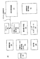
図1は、本発明の1つの実施形態による逆光補償機構110が実施されることが可能な画像取り込みデバイス(たとえば、カメラ)100を示す。画像取り込みデバイスは、光学部品120、距離計器130、光計器140、画像処理電子部品150、自動フォーカス電子部品160、露出電子部品170、自動フラッシュ電子部品180、およびユーザインターフェース電子部品190を含む。これらの構成要素は、当業者に既知であるため、本明細書では述べられないであろう。
[Image capture device]
FIG. 1 illustrates an image capture device (eg, camera) 100 in which a
画像取り込みデバイス110は、限定はされないが、フィルムカメラ、デジタルカメラ、マシン・ビジョン用途向け画像センサ、または科学的用途(たとえば、遠隔検知用途)あるいは製造用途(たとえば、アセンブリライン用途)において用いられる画像センサとすることができる。
The
画像取り込みデバイスはまた、フラッシュ104、および提供されるとフラッシュ104を起動するためのフラッシュ制御信号108を含む。
The image capture device also includes a
画像取り込みデバイスは、シーンにおける逆光条件を補償するための逆光補償機構(BCM)110を含む。BCM110は、デバイス取り込みデバイス100における他の構成要素からの情報および入力を受け取ることができる。たとえば、BCM110は、距離計器130からのシーンにおける点または点のグループに関する距離情報、および光計器140からのシーンにおける点または点のグループに関する輝度情報を受け取ることができる。以下、図2から図4を参照しながら逆光補償機構110をさらに詳細に説明する。
The image capture device includes a backlight compensation mechanism (BCM) 110 to compensate for backlight conditions in the scene. The
BCM110は、独立型機構として実施されるか、または1つまたは複数の上記の構成要素と一体化されることができる。1つの例では、逆光補償機構110は、自動フラッシュ電子部品180と一体化されてもよい。別の例では、逆行補償機構110は、自動フォーカス電子部品160または自動露出電子部品170と一体化されてもよい。
The
[逆光補償機構(BCM)110]
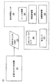
図2は、本発明の1つの実施形態に従って、図1の逆光補償機構110をさらに詳細に示すブロック図である。逆光補償機構110は、フラッシュを用いて、さらに具体的には、フラッシュを起動するためのフラッシュ制御信号を提供することによって、あるシーンにおける逆光条件を補償する。
[Backlight compensation mechanism (BCM) 110]
FIG. 2 is a block diagram illustrating the
逆光補償機構110は、シーンから受け取った情報に基づいて、シーンに対する計量マトリクス214を生成するための計量マトリクス生成器210を含む。計量マトリクス214は、複数の点を含み、各点は、輝度情報および距離情報を含む。以下、図5を参照しながら例示的な計量マトリクス214をさらに詳細に説明する。
The
逆光補償機構110は、計量マトリクス214を受け取り、計量マトリクス214に基づいてフラッシュ制御信号108を選択的に提供するための計量マトリクス生成器210に接続された逆光補償ユニット220(本明細書では、フラッシュコントローラ220とも呼ばれる)を含む。
The
逆光補償ユニット220は、シーンにおける複数の点を被写体グループと背景グループとに分割するためのシーン分割器230を含む。逆光補償ユニット220は、被写体グループ内の点および背景グループ内の点の輝度情報に基づいて、フラッシュ制御信号を選択的に提供するための輝度評価器240を含む。逆光補償ユニット220はまた、被写体グループ内の点および背景グループ内の点の距離情報に基づいて、フラッシュ制御信号を選択的に提供するための距離評価器250を含む。
The
本発明による逆光補償機構は、距離情報のみ、輝度情報のみ、またはその組み合わせを用いて、フラッシュ制御信号108を提供するかどうかを判定することができることに留意されたい。さらに、本発明による逆光補償機構は、1)カメラと被写体の1つまたは複数の点との距離、2)カメラと背景にある1つまたは複数の点との距離、3)被写体にある1つまたは複数の点の輝度、4)背景にある1つまたは複数の点の輝度、5)シーンの全体的な輝度、またはその組み合わせを用いて、フラッシュ制御信号108を提供するかどうかを判定することができる。1つまたは複数の上記の要因がどのようにフラッシュ制御信号108を選択的に提供するために用いられるかに関する2つの例示的な実施形態が、図3および図4を参照して記載される。
It should be noted that the backlight compensation mechanism according to the present invention can determine whether to provide the
逆光補償ユニット220はまた、カメラと被写体グループ内の点との距離を測定するためのスポットフォーカスセンサ260、およびシーンの全体的な輝度レベルを測定するための総合光センサ270を含むことができる。
The
[処理ステップ−第1の実施形態]
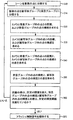
図3は、本発明の1つの実施形態に従って、逆光補償機構によって実施されるステップを示すフローチャートである。まず、計量マトリクスがシーンに対して生成される。計量マトリクスは、複数の点を含み、各点は、輝度情報および距離情報を含むことができる。計量マトリクスを生成するステップは、以下のサブステップを含むことができる。ステップ310では、シーンは、複数の点に分割される。ステップ314では、複数の点は、被写体グループと背景グループとに分類される。以下、図5から図8を参照しながら例示的な計量マトリクスをさらに詳細に示す。
[Processing Steps-First Embodiment]
FIG. 3 is a flowchart illustrating the steps performed by the backlight compensation mechanism in accordance with one embodiment of the present invention. First, a metric matrix is generated for the scene. The metric matrix includes a plurality of points, and each point can include luminance information and distance information. The step of generating a metric matrix can include the following sub-steps. In
いったん生成されると、計量マトリクスは、フラッシュ制御信号を選択的に提供するために用いられる。計量マトリクスを用いてフラッシュ制御信号を選択的に提供するステップは、以下のサブステップを含むことができる。ステップ320では、カメラと背景グループ内の点との距離、および背景グループ内の点の輝度が求められる。ステップ330では、カメラと被写体グループ内の点との距離、および被写体グループ内の点の輝度が求められる。
Once generated, the metric matrix is used to selectively provide flash control signals. The step of selectively providing the flash control signal using the metric matrix can include the following sub-steps. In
ステップ340では、カメラと背景グループ内の点との距離と、カメラと被写体グループ内の点との距離との差が計算される。ステップ350では、背景グループ内の点の輝度と、被写体グループ内の点の輝度との差も計算される。ステップ360では、距離の差が、所定の閾値を越えるかどうか、および背景グループ内の点の輝度と被写体グループ内の点の輝度との差が所定の輝度閾値を越えるかどうかが判定される。距離の差が所定の閾値を越え、背景グループ内の点の輝度と被写体グループ内の点の輝度との差が所定の輝度閾値を越えると、フラッシュ制御信号はステップ370において提供される。たとえば、背景が、被写体と比較して画像取り込みデバイスから離れており、背景が被写体と比較して比較的明るいとき、フラッシュは、本発明による逆光補償機構によって提供される。そうでないときには、フラッシュ制御信号は提供されず、処理は、処理ステップ310で続行する。
In
[処理ステップ−第2の実施形態]
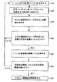
図4は、本発明の第2の実施形態に従って、逆光補償機構によって実施されるステップを示すフローチャートである。ステップ410では、シーンに対する計量マトリクスが生成される。計量マトリクスは、複数の点を含み、各点は、輝度情報および距離情報を含む。ステップ420では、フラッシュ制御信号は、計量マトリクスに基づいて、選択的に提供される。計量マトリクスに基づいてフラッシュ制御信号を選択的に提供するステップは、以下のサブステップを含むことができる。
[Processing Steps-Second Embodiment]
FIG. 4 is a flowchart illustrating steps performed by the backlight compensation mechanism in accordance with the second embodiment of the present invention. In
ステップ430では、カメラと被写体グループ内の点(または、点のグループ)との間の距離が距離計器130によって求められる。ステップ440では、カメラと被写体グループ内の点との距離が所定の距離未満であるかどうかが判定される。カメラと被写体グループ内の点との距離が所定の距離未満でないとき、処理は、ステップ410に進む。
In
カメラと被写体グループ内の点との距離が所定の距離未満であるとき、ステップ450では、シーンの全体的な輝度レベルが求められる。シーンの全体的な輝度レベルは、画像取り込みデバイスの光計器140によって供給され、シーンの全画素または所定のロケーションにおける画素の所定のグループ(たとえば、シーンの中心付近の画素のグループ)の平均輝度を含むことができる。ステップ460では、全体的な輝度レベルが所定の輝度閾値を越えるかどうかが判定される。全体的な輝度レベルが所定の輝度閾値を越えると、ステップ470では、フラッシュ制御信号が提供される。
When the distance between the camera and the point in the subject group is less than the predetermined distance, at
あるいは、特定の輝度レベルは、ステップ450から470において用いられることができる。この場合、以下のステップが実施されることができる。まず、背景グループ内の点の輝度が求められる。次いで、被写体グループ内の点の輝度が求められる。次に、背景グループ内の点の輝度と、被写体グループ内の点の輝度との差が計算される。次に、背景グループ内の点の輝度と、被写体グループ内の点の輝度との差が所定の輝度閾値を越えるかどうかが判定される。その差が所定の閾値を越えるとき、フラッシュ信号が提供される。 Alternatively, a specific brightness level can be used in steps 450-470. In this case, the following steps can be performed. First, the brightness of points in the background group is determined. Next, the luminance of the points in the subject group is determined. Next, the difference between the brightness of the points in the background group and the brightness of the points in the subject group is calculated. Next, it is determined whether the difference between the luminance of the points in the background group and the luminance of the points in the subject group exceeds a predetermined luminance threshold. When the difference exceeds a predetermined threshold, a flash signal is provided.
別の実施形態では、ステップ450から470は、ステップ430および440を実施しないで行われてもよい。本実施形態では、距離は用いられず、フラッシュ制御信号の選択的なアサーションは、シーンの全体的な輝度レベルによって決まる。フラッシュ制御信号を選択的に提供するステップは、距離情報、輝度情報(たとえば、被写体にある点と背景にある点との全体的な輝度差または特定の輝度差)に基づいていてもよいことに留意されたい。
In another embodiment, steps 450-470 may be performed without performing
[例示的な計量マトリクス]
図5は、本発明によって用いられることが可能な例示的な計量マトリクス500を示す。マトリクス500は、「B」で示される背景点520と、「S」で示される被写体点530とに分類される複数の点510を含む。背景点520はまた、本明細書では、周囲点内の点とも呼ばれる。本発明による点の数、被写体にある点のパターン、周囲または背景にある点のパターンは、特定の用途に適するように変更され調整されてもよいことに留意されたい。本実施例では、背景にある点は、逆さまの「U」を形成し、被写体にある点は「I」形状を形成する。しかし、背景または周囲にある点、および被写体にある点は、他の連続または不連続の形状およびパターンの形態であってもよいことに留意されたい。本発明による逆光補償機構によって用いられることが可能な異なる計量マトリクスの限定されないさらなる例は、本明細書では以下に記載される。
[Example Metric Matrix]
FIG. 5 shows an exemplary
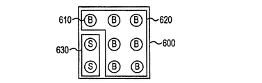
図6は、本発明によって用いられることが可能な別の例示的な計量マトリクス600を示す。マトリクス600は、「B」で示される背景点620(本明細書では、「周囲」点とも呼ばれる)と、「S」で示される被写体点630とに分類される複数の点610を含む。この計量マトリクス600は、シーンの左境界部付近にあるかまたはこれに沿って配置された被写体に特に適切である。本発明による点の数、被写体にある点のパターン、周囲または背景にある点のパターンは、特定の用途に適するように変更され調整されてもよいことに留意されたい。
FIG. 6 shows another exemplary
図7は、本発明によって用いられることが可能なさらに別の例示的な計量マトリクス700を示す。マトリクス700は、「B」で示される背景点720(本明細書では、「周囲」点とも呼ばれる)と、「S」で示される被写体点730とに分類される複数の点710を含む。この計量マトリクス700は、シーンの右境界部付近にあるかまたはこれに沿って配置された被写体に特に適切である。本発明による点の数、被写体にある点のパターン、周囲または背景にある点のパターンは、特定の用途に適するように変更され調整されてもよいことに留意されたい。
FIG. 7 shows yet another exemplary
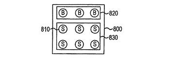
図8は、本発明によって用いられることが可能な別の例示的な計量マトリクス800を示す。マトリクス800は、「B」で示される背景点820(本明細書では、「周囲」点とも呼ばれる)と、「S」で示される被写体点830とに分類される複数の点810を含む。この計量マトリクス800は、シーンの下部付近に配置された被写体に特に適切である。本発明による点の数、被写体にある点のパターン、周囲または背景にある点のパターンは、特定の用途に適するように変更され調整されてもよいことに留意されたい。
FIG. 8 shows another exemplary
たとえば、2つの行の被写体点および第3の行の背景点を含む計量マトリクスは、シーンの上部付近に配置された被写体に対して適切であろう。 For example, a metric matrix that includes two rows of subject points and a third row of background points would be appropriate for subjects located near the top of the scene.
シーンの各領域は、「B」もしくは「S」のいずれかのラベルを有する一重丸または点で示されることに留意されたい。しかし、一重丸または点は、被写体または背景のいずれかを表す複数の点を示すことができる。複数の点はまた、図示される円形形状以外の形状を形成することもできる。たとえば、直線縁部または非直線縁部を有する形状を、計量マトリクスにおいて用いることもできる。 Note that each area of the scene is indicated by a single circle or dot with a label of either “B” or “S”. However, a single circle or point can indicate a plurality of points representing either the subject or the background. The plurality of points can also form shapes other than the circular shape shown. For example, shapes with straight edges or non-straight edges can be used in the metric matrix.
逆光条件を有するシーンは、本発明による逆光補償機構の恩恵を受けるであろう。たとえば、逆光条件を有するシーンは、通常、複数の点を含み、これらの点は、背景点または周囲点と被写体点とに配列され、周囲にある点は、被写体にある点と比較して取り込みデバイスから離れており、被写体にある点よりも輝度の点でより明るい。対照的に、被写体にある点は、周囲にある点よりも輝度が低く、画像取り込みデバイスにより近い。 Scenes with backlight conditions will benefit from the backlight compensation mechanism according to the present invention. For example, a scene with backlight conditions typically includes a plurality of points that are arranged as background points or surrounding points and subject points, and the surrounding points are captured relative to the points on the subject. It is far from the device and brighter in terms of brightness than the point on the subject. In contrast, points on the subject have lower brightness and are closer to the image capture device than surrounding points.
逆光条件を有するシーンの例として、背景に光源(たとえば、街灯または他の自然あるいは人工の光源)が存在するシーンが挙げられる。逆光条件を有するこのようなシーンは、取り込まれると、望ましくないほど明るい背景と暗い被写体を有する品質の悪い写真となるであろう。逆光条件を自動的に検出し、フラッシュを提供することによって、本発明の露出補償機構は、逆光条件を検出し、(たとえば図4に従って)フラッシュを動作可能にし、それによって、取り込まれた写真に望ましい露出(たとえば、明るい被写体)を得る。 An example of a scene having a backlight condition is a scene where a light source (eg, a streetlight or other natural or artificial light source) is present in the background. Such a scene with backlight conditions would result in a poor quality photo with an undesirably bright background and dark subject when captured. By automatically detecting backlight conditions and providing a flash, the exposure compensation mechanism of the present invention detects the backlight conditions and enables the flash (eg, according to FIG. 4), thereby enabling the captured photo to be captured. Get the desired exposure (eg, bright subject).
遅い同期条件を有するシーンは、本発明による逆光補償機構から恩恵を受けるであろう。たとえば、遅い同期条件を有するシーンは、通常、背景または周囲点と、「S」で示される被写体点とに分類される複数の点を含む。周囲にある点は、被写体にある点と比較すると画像取り込みデバイスから離れており、被写体にある点よりも輝度に関してより暗い。この場合、被写体にある点もまた、輝度に関して暗いが、周囲にある点よりも画像取り込みデバイスにより近い。本発明の露出補償機構がなければ、遅い同期条件を有するシーンは、露出過度の被写体および露出不足の背景を目立たせる、品質の低い写真を含む撮影となる。 Scenes with slow synchronization conditions will benefit from the backlight compensation mechanism according to the present invention. For example, a scene with a slow synchronization condition typically includes a plurality of points that are classified as background or surrounding points and subject points denoted by “S”. The surrounding points are farther from the image capture device than the points on the subject and are darker in terms of brightness than the points on the subject. In this case, the point on the subject is also dark with respect to brightness, but closer to the image capture device than the surrounding points. Without the exposure compensation mechanism of the present invention, a scene having a slow synchronization condition results in a shot including a low quality photo that highlights an overexposed subject and an underexposed background.
場合によっては、フラッシュを用いて撮影された写真は、黒いまたは非常に暗い背景に対して良好に露出された前景の被写体を示すため、望ましくない効果を与える。本発明による露出補償機構は、通常よりも長くシャッターを開いておき、背景を明るくすることによって、この問題を軽減する遅い同期モードを提供する。 In some cases, a photograph taken with a flash gives an undesirable effect because it shows a well-exposed foreground subject against a black or very dark background. The exposure compensation mechanism according to the present invention provides a slow sync mode that alleviates this problem by keeping the shutter open longer than usual and brightening the background.
たとえば、1つの実施形態では、露出補償機構は、遅く同期されたモードにおける遅いシャッター速度を用いて、迅速に移動する物体またはカメラブレから生じるぼけを画像におけるぼけに見えるようにする。ぼけを避けるために、三脚を用いるかまたは単に静止した被写体(たとえば、移動していない被写体)を撮影してもよい。 For example, in one embodiment, the exposure compensation mechanism uses a slow shutter speed in a slow synchronized mode to make blurs resulting from fast moving objects or camera shake appear as blurs in the image. To avoid blurring, a tripod may be used or a stationary subject (eg, a subject that has not moved) may be photographed.
本発明による露出補償機構は、写真撮影において特別な効果を生じるように用いられることができる。たとえば、長いシャッター速度と組み合わせた短いフラッシュバーストは、興味深い特別な効果を提供する。短いフラッシュバーストは、物体を鮮明に静止させ、次に、薄暗い周囲光は、画像をわずかにぼやけさせ、それによって、移動する光が写真撮影における光の流れ(streak)に見えるようにする。 The exposure compensation mechanism according to the present invention can be used to produce a special effect in photography. For example, a short flash burst combined with a long shutter speed provides an interesting special effect. A short flash burst causes the object to be sharply stationary, and then the dim ambient light slightly blurs the image, thereby allowing the moving light to appear as a light stream in photography.
遅い同期条件を自動的に検出し、フラッシュを発足させ、露出を調整することによって、本発明の露出補償機構は、取り込まれた写真が望ましい露出を有するようにする。 By automatically detecting slow sync conditions, initiating flash and adjusting exposure, the exposure compensation mechanism of the present invention ensures that the captured photo has the desired exposure.
本発明による露出補償機構は、暗い背景に対して良好に露出された前景を検出し、フラッシュおよびシャッタータイミングを選択的に制御してこの状況を補償する。たとえば、遅い同期状況がいったん検出されると、本発明による露出補償機構は、フラッシュを被写体に露出させ、背景を露出するためにより長い露出時間を設定することができる。 The exposure compensation mechanism according to the present invention detects a well-exposed foreground against a dark background and selectively controls flash and shutter timing to compensate for this situation. For example, once a slow sync situation is detected, the exposure compensation mechanism according to the present invention can expose the flash to the subject and set a longer exposure time to expose the background.
本発明の原理は、画像取り込みデバイス(たとえば、フィルムに基づいたまたはフィルムのないカメラ)に関して記載されている。しかし、本発明の教示が、マシン・ビジョン用途において用いられる画像センサ等の他のセンサおよび他の用途に適用されることができることに留意されたい。 The principles of the present invention are described with respect to an image capture device (eg, a film-based or film-less camera). However, it should be noted that the teachings of the present invention can be applied to other sensors and other applications, such as image sensors used in machine vision applications.
上記の本明細書では、本発明は、その具体的な実施形態を参照しながら説明されている。しかし、様々な変更および変形が本発明のより広い範囲から逸脱せずに行われてもよいことは明白である。したがって、本明細書および図面は、限定の意味ではなく、むしろ例示の意味で見なされる。 In the foregoing specification, the invention has been described with reference to specific embodiments thereof. It will be apparent, however, that various changes and modifications may be made without departing from the broader scope of the invention. The specification and drawings are, accordingly, to be regarded in an illustrative sense rather than a restrictive sense.
Claims (6)
b)シーンから受け取った情報に基づいて計量マトリクスを生成するための計量マトリクス生成器と、ここで、前記計量マトリクスは、複数の点を含み、各点は、距離情報および輝度情報を含むものであって、
c)前記計量マトリクスを受け取り、前記計量マトリクスに基づいて前記フラッシュ制御信号を選択的に提供するための、前記計量マトリクス生成器に接続された逆光補償ユニットであって、シーン内の前記複数の点を被写体グループと背景グループとに分割するためのシーン分割器と、前記カメラと前記被写体グループ内の点との距離を測定するためのスポットフォーカスセンサと、前記シーンの全体的な輝度レベルを測定するための総合光センサとを有する、逆光補償ユニットと
を備えるシーンを取り込むためのカメラであって、
前記カメラと前記被写体グループ内の点との距離を求め、前記カメラと前記被写体グループ内の点との距離が、所定の距離未満であるかどうかを判定し、前記カメラと前記被写体グループ内の点との距離が所定の距離未満であるとき、前記シーンの全体的な輝度レベルを求め、前記全体的な輝度レベルが所定の輝度閾値を越えるかどうかを判定し、前記全体的な輝度レベルが所定の輝度閾値を越えるとき、前記フラッシュ制御信号を提供することを特徴とする、カメラ。 a) a flash for emitting light in response to a provided flash control signal;
b) a metric matrix generator for generating a metric matrix based on information received from the scene, wherein the metric matrix includes a plurality of points, each point including distance information and luminance information; There,
c) a backlight compensation unit connected to the metric matrix generator for receiving the metric matrix and selectively providing the flash control signal based on the metric matrix , the plurality of points in the scene A scene divider for dividing the image into a subject group and a background group, a spot focus sensor for measuring the distance between the camera and a point in the subject group, and an overall luminance level of the scene and a total light sensor for, a camera for capturing a scene and a backlit compensation unit,
A distance between the camera and a point in the subject group is obtained, a distance between the camera and the point in the subject group is determined to be less than a predetermined distance, and a point in the camera and the subject group is determined. Is less than a predetermined distance, an overall luminance level of the scene is obtained, it is determined whether the overall luminance level exceeds a predetermined luminance threshold, and the overall luminance level is predetermined. The flash control signal is provided when a luminance threshold of the camera is exceeded.
前記被写体グループ内の点および前記背景グループ内の点の輝度情報に基づいて前記フラッシュ制御信号を選択的に提供するための輝度評価器と、
前記被写体グループ内の点および前記背景グループ内の点の距離情報に基づいて前記フラッシュ制御信号を選択的に提供するための距離評価器と
をさらに備える請求項1に記載のカメラ。 The backlight compensation unit is
A luminance evaluator for selectively providing the flash control signal based on luminance information of points in the subject group and points in the background group;
The camera according to claim 1, further comprising: a distance evaluator for selectively providing the flash control signal based on distance information of the points in the subject group and the points in the background group.
前記背景補償ユニットは、前記距離の差が、所定の距離閾値を越えるかどうかを判定し、前記輝度の差が、所定の輝度閾値を越えるかどうかを判定して、前記距離の差が所定の距離閾値を越えるとき、及び前記輝度の差が所定の輝度閾値を越えるとき、前記フラッシュ制御信号を提供する請求項3に記載のカメラ。 The luminance evaluator obtains the luminance of the point in the subject group, obtains the luminance of the point in the background group, and subsequently calculates the luminance of the point in the background group and the luminance of the point in the subject group. Find the difference
The background compensation unit determines whether the distance difference exceeds a predetermined distance threshold, determines whether the brightness difference exceeds a predetermined brightness threshold, and the distance difference is a predetermined distance threshold. 4. The camera of claim 3, wherein the flash control signal is provided when a distance threshold is exceeded and when the brightness difference exceeds a predetermined brightness threshold.
前記シーンの輝度情報を測定するための手段と
をさらに備える請求項1に記載のカメラ。 Means for measuring distance information of the scene;
The camera of claim 1, further comprising: means for measuring luminance information of the scene.
Applications Claiming Priority (1)
| Application Number | Priority Date | Filing Date | Title |
|---|---|---|---|
| US10/714,301 US6859618B1 (en) | 2003-11-15 | 2003-11-15 | Exposure compensation method and system employing meter matrix and flash |
Publications (2)
| Publication Number | Publication Date |
|---|---|
| JP2005151574A JP2005151574A (en) | 2005-06-09 |
| JP4068614B2 true JP4068614B2 (en) | 2008-03-26 |
Family
ID=34136870
Family Applications (1)
| Application Number | Title | Priority Date | Filing Date |
|---|---|---|---|
| JP2004330911A Expired - Fee Related JP4068614B2 (en) | 2003-11-15 | 2004-11-15 | Exposure compensation method and system using metric matrix and flash |
Country Status (3)
| Country | Link |
|---|---|
| US (1) | US6859618B1 (en) |
| EP (1) | EP1531356A1 (en) |
| JP (1) | JP4068614B2 (en) |
Families Citing this family (20)
| Publication number | Priority date | Publication date | Assignee | Title |
|---|---|---|---|---|
| JP2005181355A (en) * | 2003-12-15 | 2005-07-07 | Canon Inc | Imaging device |
| US8482618B2 (en) * | 2005-02-22 | 2013-07-09 | Hewlett-Packard Development Company, L.P. | Reduction of motion-induced blur in images |
| US7546026B2 (en) * | 2005-10-25 | 2009-06-09 | Zoran Corporation | Camera exposure optimization techniques that take camera and scene motion into account |
| US20070222859A1 (en) * | 2006-03-23 | 2007-09-27 | Coban Research And Technologies, Inc. | Method for digital video/audio recording with backlight compensation using a touch screen control panel |
| JP2007266692A (en) * | 2006-03-27 | 2007-10-11 | Fujifilm Corp | Imaging method and apparatus |
| US7697836B2 (en) * | 2006-10-25 | 2010-04-13 | Zoran Corporation | Control of artificial lighting of a scene to reduce effects of motion in the scene on an image being acquired |
| US8331721B2 (en) * | 2007-06-20 | 2012-12-11 | Microsoft Corporation | Automatic image correction providing multiple user-selectable options |
| JP5127317B2 (en) * | 2007-06-25 | 2013-01-23 | 三洋電機株式会社 | camera |
| KR100950465B1 (en) * | 2007-12-21 | 2010-03-31 | 손승남 | Camera Control Method for Vehicle Access Control System |
| TW200928574A (en) * | 2007-12-31 | 2009-07-01 | Altek Corp | Automatic exposure control method |
| US8482620B2 (en) | 2008-03-11 | 2013-07-09 | Csr Technology Inc. | Image enhancement based on multiple frames and motion estimation |
| TWI397053B (en) * | 2008-03-14 | 2013-05-21 | Innolux Corp | Liquid crystal display device capable of automatically adjusting brightness and method thereof |
| JP5451316B2 (en) * | 2009-10-28 | 2014-03-26 | キヤノン株式会社 | Imaging apparatus and light emission control method |
| JP5597078B2 (en) * | 2010-09-17 | 2014-10-01 | キヤノン株式会社 | Imaging apparatus and control method thereof |
| JP5932240B2 (en) * | 2011-05-13 | 2016-06-08 | キヤノン株式会社 | Imaging apparatus and control method |
| CN103634528B (en) | 2012-08-23 | 2017-06-06 | 中兴通讯股份有限公司 | Method for compensating backlight, device and terminal |
| TWI466080B (en) * | 2012-12-10 | 2014-12-21 | Novatek Microelectronics Corp | Backlight module and switching method |
| KR20140093513A (en) * | 2013-01-18 | 2014-07-28 | 삼성전자주식회사 | Apparatus and method for controlling display of mobile terminal |
| CN104883509B (en) * | 2015-04-30 | 2017-11-24 | 广东欧珀移动通信有限公司 | Method and terminal for shooting by using flash lamp |
| CN109283651B (en) * | 2018-12-12 | 2021-12-14 | 广东奥普特科技股份有限公司 | A compact high-resolution machine vision lens structure |
Family Cites Families (11)
| Publication number | Priority date | Publication date | Assignee | Title |
|---|---|---|---|---|
| US4664495A (en) * | 1984-04-09 | 1987-05-12 | Canon Kabushiki Kaisha | Rear light detecting device for camera |
| US4941009A (en) * | 1988-07-07 | 1990-07-10 | Konica Corporation | Method for slow synchro-flash photography |
| JPH03223821A (en) * | 1990-01-30 | 1991-10-02 | Canon Inc | camera |
| JP2934712B2 (en) * | 1990-02-19 | 1999-08-16 | 株式会社ニコン | Camera backlight detection device |
| US5289227A (en) * | 1992-01-22 | 1994-02-22 | Fuji Photo Film Co., Ltd. | Method of automatically controlling taking exposure and focusing in a camera and a method of controlling printing exposure |
| JPH06138364A (en) * | 1992-10-28 | 1994-05-20 | Canon Inc | Camera provided with device for detecting line of sight |
| US5678098A (en) | 1994-06-09 | 1997-10-14 | Fuji Photo Film Co., Ltd. | Method and apparatus for controlling exposure of camera |
| KR0160191B1 (en) | 1995-08-12 | 1999-01-15 | 김광호 | Method & apparatus for back light correction |
| US6240253B1 (en) * | 1998-09-14 | 2001-05-29 | Minolta Co., Ltd. | Automatic focusing camera |
| US6516147B2 (en) * | 1999-12-20 | 2003-02-04 | Polaroid Corporation | Scene recognition method and system using brightness and ranging mapping |
| JP2002221747A (en) * | 2001-01-25 | 2002-08-09 | Nikon Corp | Camera backlight detection device |
-
2003
- 2003-11-15 US US10/714,301 patent/US6859618B1/en not_active Expired - Fee Related
-
2004
- 2004-05-19 EP EP04011921A patent/EP1531356A1/en not_active Withdrawn
- 2004-11-15 JP JP2004330911A patent/JP4068614B2/en not_active Expired - Fee Related
Also Published As
| Publication number | Publication date |
|---|---|
| US6859618B1 (en) | 2005-02-22 |
| JP2005151574A (en) | 2005-06-09 |
| EP1531356A1 (en) | 2005-05-18 |
Similar Documents
| Publication | Publication Date | Title |
|---|---|---|
| JP4068614B2 (en) | Exposure compensation method and system using metric matrix and flash | |
| JP5610762B2 (en) | Imaging apparatus and control method | |
| JP7799405B2 (en) | Imaging device, flicker detection method and program | |
| JP2001242504A (en) | Camera device | |
| TWI407780B (en) | Method for image exposure correction | |
| US10609265B2 (en) | Methods and apparatus for synchronizing camera flash and sensor blanking | |
| KR102811831B1 (en) | Image capturing apparatus capable of detecting flicker due to periodic change in light amount of object, flicker detecting method, and non-transitory computer-readable storage medium | |
| CN102469266A (en) | Imaging apparatus | |
| JP2025118949A (en) | Imaging device, control method thereof, and program | |
| TW202215834A (en) | Image capture method and system thereof | |
| JP5943561B2 (en) | Imaging device, control method thereof, and control program | |
| JP4300936B2 (en) | Imaging device | |
| JP5246590B2 (en) | Imaging apparatus, image generation method, and program | |
| JP6231814B2 (en) | EXPOSURE DETERMINING DEVICE, IMAGING DEVICE, CONTROL METHOD, AND PROGRAM | |
| JP4412109B2 (en) | Electronic camera having color balance adjustment function and program | |
| US20040022531A1 (en) | Camera lens focus setting for low brightness scenes | |
| JP2009124309A (en) | Imaging device | |
| JP2018191141A (en) | Imaging device | |
| JP2003348603A (en) | Electronic camera | |
| JP2000184381A (en) | Digital still camera | |
| JP6423669B2 (en) | Imaging apparatus and control method thereof | |
| JP2011114442A (en) | Electronic camera | |
| JP2009128707A (en) | Imaging device, photometric device, and side light method | |
| KR20090080610A (en) | Intelligent flash device and method of digital imaging device | |
| JP2007139874A (en) | Imaging device |
Legal Events
| Date | Code | Title | Description |
|---|---|---|---|
| A977 | Report on retrieval |
Free format text: JAPANESE INTERMEDIATE CODE: A971007 Effective date: 20070712 |
|
| A131 | Notification of reasons for refusal |
Free format text: JAPANESE INTERMEDIATE CODE: A131 Effective date: 20070720 |
|
| A601 | Written request for extension of time |
Free format text: JAPANESE INTERMEDIATE CODE: A601 Effective date: 20071022 |
|
| A602 | Written permission of extension of time |
Free format text: JAPANESE INTERMEDIATE CODE: A602 Effective date: 20071025 |
|
| A521 | Request for written amendment filed |
Free format text: JAPANESE INTERMEDIATE CODE: A523 Effective date: 20071120 |
|
| TRDD | Decision of grant or rejection written | ||
| A01 | Written decision to grant a patent or to grant a registration (utility model) |
Free format text: JAPANESE INTERMEDIATE CODE: A01 Effective date: 20071218 |
|
| A61 | First payment of annual fees (during grant procedure) |
Free format text: JAPANESE INTERMEDIATE CODE: A61 Effective date: 20080110 |
|
| FPAY | Renewal fee payment (event date is renewal date of database) |
Free format text: PAYMENT UNTIL: 20110118 Year of fee payment: 3 |
|
| R150 | Certificate of patent or registration of utility model |
Free format text: JAPANESE INTERMEDIATE CODE: R150 |
|
| LAPS | Cancellation because of no payment of annual fees |