JP4066713B2 - Beverage dispenser - Google Patents
Beverage dispenser Download PDFInfo
- Publication number
- JP4066713B2 JP4066713B2 JP2002142404A JP2002142404A JP4066713B2 JP 4066713 B2 JP4066713 B2 JP 4066713B2 JP 2002142404 A JP2002142404 A JP 2002142404A JP 2002142404 A JP2002142404 A JP 2002142404A JP 4066713 B2 JP4066713 B2 JP 4066713B2
- Authority
- JP
- Japan
- Prior art keywords
- beer
- beverage
- dispensing
- mug
- nozzle
- Prior art date
- Legal status (The legal status is an assumption and is not a legal conclusion. Google has not performed a legal analysis and makes no representation as to the accuracy of the status listed.)
- Expired - Fee Related
Links
Images


Landscapes
- Devices For Dispensing Beverages (AREA)
Description
【0001】
【発明の属する技術分野】
この発明は、飲料ディスペンサに関し、詳細には、傾けた飲用容器に飲料を注出する飲料ディスペンサに関する。
【0002】
【従来の技術】
従来、紙コップやグラス、ジョッキ等の飲用容器に、清涼飲料や炭酸飲料等の飲料を自動的に注ぐ飲料ディスペンサが知られている。この飲料ディスペンサは、飲料が供給される注出口に設けられた注出バルブを開閉操作することによって、注出口の下方に配設された載置台上に載置された飲用容器に、所定量の飲料を分配供給するように構成されている。
【0003】
ところで、このような飲料ディスペンサによって飲料を、載置台上に直立して載置された飲用容器内に注ぐと、飲料が飲用容器内で無用に泡立ち、飲用容器に注がれた飲料の見た目の印象が損なわれたり、飲料の風味自体が損なわれる場合がある。また、ビールや発泡酒のような発泡飲料では、泡を意図的に形成させることも行われるが、この場合でも、飲用容器内に供給される飲料が、この容器内の飲料の液面に直接注がれると、飲料に含有される炭酸ガス等の発泡ガスが過度に遊離して木目の粗い泡(自然発泡)となり、この自然発泡は飲料容量の不揃いの原因となるため、自然発泡を可能な限り減らすことが求められている。
【0004】
そこで、過度の泡立ちを抑制することが求められている飲料ディスペンサにおいては、飲料を注ぐ際に、飲用容器が載置される載置台を台傾斜手段によって、その容器が直立位置から所定角度だけ傾くように傾斜させ、注出口から供給される飲料が、傾斜された容器の内壁面に沿って下方に流れるように注出することが行われている。このように容器を傾けて飲料を注出することにより、注出された飲料は、容器内の飲料の液面に直接衝突することがないため、衝撃的な撹拌が抑制されて、発泡ガスの遊離を抑えることができるとともに、飲料を注ぐ落差を小さくすることができ、これによっても発泡ガスの遊離を抑制することができる。
【0005】
一方、飲料ディスペンサにおいては、飲用容器内に所定量の飲料を供給した後は、自動的に注出バルブを閉じて飲料の供給を停止し、過度に供給された飲料が容器から溢れるのを防止することも求められており、液面検知装置により容器に注がれた飲料の液面位置を検出して所定位置に到達したら供給を停止する方式(特許第2933530号公報、特許第2960590号公報等)など、種々の方式が提案されている。
【0006】
このように、飲料の注出量を自動定量することによって、飲料ディスペンサの操作者は飲料の供給を停止させる操作を行う必要がないため、操作者がアルバイト従業員のような非熟練者であっても、注出量のばらつきを抑えることができるとともに、注出開始ボタンを押すなどの注出バルブの開放に連動した操作を行った後は、飲料ディスペンサから目を離していてもよく、他の作業を並行して行うことができ、操作作業性が向上する。
【0007】
ところで、前述したように、飲用容器を傾斜させながら飲料を注出する方式の飲料ディスペンサにおいては、傾斜させた飲用容器を最終的には直立位置に戻す必要がある。これは、飲料ディスペンサから飲用容器を取り出し易くするとともに、傾斜させたままの容器には十分な量の飲料を供給することができず、容器を直立位置まで戻して、さらに多くの飲料を飲用容器に供給するためである。
【0008】
そして、この方式の飲料ディスペンサにおいても自動化が要望されており、この場合、傾斜させた飲用容器を直立位置まで戻す操作も自動化する必要があり、この要望に応えるものとして、液面検知装置により、傾斜させた飲用容器への飲料の泡又は液面が予め設定された位置まできたことが検知されると容器を直立位置に戻すように台傾斜手段を制御する技術が提案されている(特許第2933369号公報、特許第2960590号公報等)。
【0009】
この技術によれば、飲料の供給開始から予め設定された所定時間経過後に、傾斜された飲用容器を直立位置に戻すことによって、傾斜された飲用容器から飲料が溢れ出るのを未然に防止し、直立位置に戻された飲用容器にさらに飲料を供給することによって、十分な量の飲料を供給しつつ、最終的に飲用容器内の飲料の液面位置を検出して飲料の供給を停止することによって、自動的に定量の飲料を供給することを可能にしている。
【0010】
【発明が解決しようとする課題】
しかし、上述した液面検知装置としては、反射型光センサや超音波センサーが一般的であるが、以下の課題を有しているものである。
まず、反射型光センサは、発光/受光が一体になったものが多く、光の直進性より液面(泡面)に対して、垂直に発光/受光する必要性があり、その反射光の光量を距離に換算しているため、液面の状態により換算距離に誤差を生じ易く、しかも、外乱光の影響も受け易い問題点を有しており、また、傾いた容器(特に、細径グラス)の場合には、垂直に発光/受光しようとすると、その検出可能距離範囲は非常に狭くセンサを配置しにくい問題点がある。
【0011】
次に、超音波センサも、発信/受信が一体になったものが多く、超音波の直進性より、液面(泡面)に対して、垂直に発信/受信する必要性があり、液面の状態により換算距離に誤差を生じ易いという問題点を有しており、また、傾いた容器(特に、細径グラス)の場合には、垂直に発信/受信しようとすると、その検出可能距離範囲は非常に狭くセンサを配置しにくい問題点がある。しかも、超音波センサの場合には、その指向性より容器内壁での乱反射することで、検出距離のばらつきにつながる問題点もある。
【0012】
本発明は上記事情に鑑みてなされたものであり、飲料に対して最適なセンサを用い、飲用容器の傾斜角度を、常にタイミングよく変化させて、供給される飲料の無駄をなくした飲料ディスペンサを得ることを目的とする。
【0018】
【課題を解決するための手段】
この発明の飲料ディスペンサ(請求項1)は、飲料導管に設けられた注出バルブを開閉操作することによって、飲料の抽出を行う飲料ノズルと泡の抽出を行う泡ノズルを有したノズルの下方に配設された載置台上に載置された飲用容器に、所定量の飲料を分配供給する飲料ディスペンサにおいて、飲料の注出を開始する飲料注出開始手段と、前記載置台上に載置された飲用容器を、略直立位置から所定角度位置まで傾けるように、該載置台を傾斜させる台傾斜駆動手段と、同一平面上の予め定められた間隔に配置される1対のレンズと、このレンズの光軸後方の焦点距離の位置に配置される1対のホトアレイセンサと、該ホトアレイセンサ上の結像位置のズレ量より前記飲用容器に注出される飲料の液面までの距離を演算する演算部と、を備えるオートフォーカスセンサと補助光源とからなる光学式距離検出手段と、前記注出バルブを開閉駆動する注出バルブ駆動手段と、前記台傾斜駆動手段と注出バルブ駆動手段とを制御する制御手段とを備え、前記制御手段は、飲料注出開始手段からの信号により前記注出バルブ駆動手段を駆動して前記注出バルブを制御し、前記台傾斜駆動手段により所定角度位置に傾斜した載置台上に載置された飲用容器に前記ノズルから飲料を注出し、前記光学式距離検出手段からの検出信号に応じて台傾斜駆動手段を駆動して載置台を略直立位置に戻すよう制御し、さらに、予め定められた時間、又は演算により求められた時間に応じて前記注出バルブ駆動手段を制御してノズルからの飲料の注出を停止させ、前期光学式距離検出手段により飲料の注出の停止後の液面までの距離を検出し、この検出した液面までの距離から飲料が飲用容器から溢出しないような泡付け時間を演算し、この演算した泡付け時間に到達すると前記注出バルブを制御して泡の注出を停止することを特徴とする飲料ディスペンサ。
【0019】
この請求項1に係る飲料ディスペンサによれば、予め定められた時間、又は演算で求められた時間は、飲用容器に注がれた飲料が、この飲用容器から溢れ出ない範囲の飲料の注出時間として、実験あるいは経験的に予め設定されたものであってもよいし、気温の変動等の環境変化に基づいてその都度演算された注出時間であってもよい。また、請求項1に係わる飲料ディスペンサにおいては、容器から溢れることなく、確実に泡の抽出を停止させることができる。
【0025】
【発明の実施の形態】
以下、この発明に係る飲料ディスペンサの実施の形態につき、図面を参照して詳細に説明する。
【0026】
図1は、この発明に係る飲料ディスペンサの実施の形態であるビールディスペンサの要部を示す図、図2は、図1に示したビールディスペンサを含むビール供給システムの全体図、図3は、図1に示したビールディスペンサの制御装置の制御ブロック図である。
【0027】
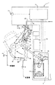
図1に示したビールディスペンサ1には、図2に示すように、飲料容器であるビール樽40が、外部導管によって接続されており、このビール樽40には、炭酸ガスを供給するガスボンベ30が接続されている。ガスボンベ30から供給された炭酸ガスによって、ビール樽40の内部は加圧され、この供給された炭酸ガスの一部は、ビール樽40内部に収容された飲料であるビール41に溶け込む。このとき、ガスボンベ30からビール樽40に供給される炭酸ガスの圧力は、ガスボンベ30に取り付けられた減圧弁によって、ビール樽40内のビール41の温度に応じて、適切に調整される。
【0028】
ビール樽40に収容されたビール41は、供給された炭酸ガスによって加圧されて、ビールディスペンサ1に供給される。このビールディスペンサ1に供給されたビール41は、このビールディスペンサ1の導管22の内部を通過して、ビールノズル6から注出され、ジョッキ支持台4(載置台4)上にセットされた飲用容器であるビールジョッキ50に注がれる。ビールディスペンサ1の導管22は、冷却ユニット24によって冷却された冷却水槽23内を、螺旋渦巻状に形成されて通過しており、導管22内を通過するビール41は、この冷却水槽23内を通過する間に、所定の温度まで冷却されるように構成されている。
【0029】
導管22の吐出端には、ビールノズル6と泡ノズル2とからなるノズルおよび注出バルブ20からなる略逆V字状の注出タップが取り付けられており、この注出タップの下方に、ジョッキ支持台4が配設されている。注出タップのビールノズル6は、導管22を通過したビール41を注出するノズルであり、泡ノズル2は、導管22を通過したビール41を、内部に形成された細孔を通過させて所定の壁面に勢いよく衝突させることによって、ビール41を木目細かいクリーミーな泡状にして注出するノズルである。
【0030】
注出バルブ20は、ビールノズル6からのビール41の注出と、泡ノズル2からの泡の注出と、ビール41および泡の注出の停止と、をそれぞれ切り換えるバルブであり、注出バルブ20の開閉切換えは、注出バルブ駆動部12から伝達される駆動力によって行われる。
【0031】
また、101は、ビールジョッキ内の液面までの距離を検出する光学式距離検出手段であり、図示では光学式距離検出手段101は、ビールジョッキ50の斜め上方で、液面に到達する光がノズルとノズルから吐出する飲料とに干渉しない適宜位置に設けられるものである。なお、光学式距離検出手段101として用いる三角測距方式のオートフォーカスセンサの検出原理は、同出願人が先に出願した特願2002−005429号に記載したとおりであり、ここでは詳細説明を省略する。
【0032】
すなわち、光学式距離検出手段は、同一平面上の予め定められた間隔に配置される1対のレンズと、このレンズの光軸後方の焦点距離の位置に配置される1対のホトアレイセンサと、を有してなるAFモジュールと、このホトアレイセンサ上の結像位置のズレ量より被測定物体までの距離を演算する演算部と、を備えてなるオートフォーカスセンサ(AFセンサ)101aと、この測距イメージセンサの近傍に配置され帯状の光線を放射する補助光源101bと、を備えて構成するものである。
【0033】
注出タップの下方に設けられたジョッキ支持台4は、ビールジョッキ50の底面を支持する略円板状の底板と、ビールジョッキ50の周面の一部を支持する平板状の突当て板と、後述する、ジョッキ支持台4を傾斜させるロッド15の先端受部19に係合されるフック板とからなり、図1に示すように断面略逆L字状に形成されており、この断面略逆L字の上端部(図1において、右上角部)Aを中心として、図面紙面内で、略直立位置(鉛直方向に対して角度α(0°≦α≦10°))と傾斜位置(鉛直方向に対して角度β(β≒60°))との角度範囲(α≦θ≦β)において、回動自在に、ビールディスペンサ1の本体ケースに軸支されている。この上端部Aを軸支する本体ケース側の軸部は、図示右向き水平に移動可能に配設されている。
なお、ジョッキ支持台4は、ビールジョッキ50の大きさ(例えば、小ジョッキ、大ジョッキ等)に応じて高さの異なる複数の底板を選択的に使用することが可能なものであってもよいし、また、ビールジョッキ50の大きさに応じて昇降可能な底板を有するものであってもよい。
【0034】
また、このビールディスペンサ1には、ジョッキ支持台4を上述した角度範囲で回動させてビールジョッキ50を傾斜させる台傾斜手段として、支持台駆動部3が設けられている。この支持台駆動部3は、詳しくは、ジョッキ支持台4の突当て板を押圧してジョッキ支持台4を傾けるロッド15と、支持台駆動モータ14と、支持台駆動モータ14の駆動力をロッド15に伝達して、ロッド15を、その延在方向に移動させるリンク機構13とからなる。なおロッド15の先端部には、先端受部19が設けられている。
【0035】
さらに、ビールディスペンサ1には、制御装置7が備えられているが、この制御装置7は、図3に示す制御ブロック図に示すように、オートフォーカスセンサ101aおよび注出ボタン11からの入力に応じて、注出バルブ駆動部12および支持台駆動部3を制御している。ここで、図1,3において注出ボタン11は、1個のみ記載しているが、複数個の注出ボタン(例えば、小ジョッキ注出ボタン、中ジョッキ注出ボタン、大ジョッキ注出ボタン等)を備える場合もある。この制御装置7は、ビールノズル6からビール41の注出を開始させる信号を与える注出ボタン11から入力された信号を受けて、支持台駆動部4をON状態に切り換え、ロッド15を実線位置から二点鎖線位置まで移動させ、ジョッキ支持台4を傾斜位置(θ=β)まで傾斜させるとともに、注出バルブ駆動部12をON状態に切り換え、注出バルブ20を開状態として、ビールノズル6からビール41の注出を開始させ、さらに、オートフォーカスセンサ101によって検出されたビールジョッキ50の液面に応じて、ジョッキ支持台4を傾斜位置(傾斜角度θ=β)から、元の略直立位置(θ=α)に戻すように、支持台駆動部3を制御している。
【0036】
また、制御装置7は、ジョッキ支持台4が略直立位置(θ=α)まで戻された後に、オートフォーカスセンサ101aによって検出されたビールジョッキ50に注出される液面までの距離に応じて、注出バルブ駆動部12をOFF状態にして、ビールノズル6からのビール41の注出を停止させるように、注出バルブ駆動部12を制御している。
【0037】
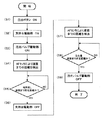
次に、この実施の形態のビールディスペンサ1の第1の実施例について、図4に示したフローチャートを参照しつつ、説明する。
まず、このビールディスペンサ1の導管22には、前述したビール樽40から圧送されて、冷却水槽23によって冷却されたビール41が満たされており、閉鎖されている注出バルブ20によって、供給が停止された状態となっている。
【0038】
ここで、オペレータは、初期状態である略直立位置(傾斜角度α)にセットされているジョッキ支持台4上に、空のビールジョッキ50を載置し、注出ボタン11を押す。この操作によって、注出ボタン11がON状態であることを表す信号が制御装置7に入力される(ステップS1)。
【0039】
制御装置7は、この信号の入力によって、支持台駆動部3をON状態に切り換え(ステップS2)、ON状態とされた支持台駆動部3は、支持台駆動モータ14が回転駆動し、この支持台駆動モータ14の回転がリンク機構13に伝達され、さらにロッド15に伝達されて、ロッド15は、図示の実線位置から二点鎖線の位置に直進移動される。この移動によって、ロッド15の先端に設けられた先端受け19が、略直立位置にあるジョッキ支持台4の突当て板の背面側を押圧し、ジョッキ支持台4は、上端部Aを回動中心として、ロッド15の移動後の位置(二点鎖線)に対応する傾斜位置(傾斜角度β;二点鎖線で示す)まで傾斜する。
【0040】
次いで、制御装置7は、注出バルブ駆動部12をON状態とし(ステップS3)、このON状態とされた注出バルブ駆動部12は、注出タップ内に設けられた注出バルブ20を開放状態に切り換える。この結果、注出タップのビールノズル6から、導管22内を圧送されたビール41が注出され、傾斜位置にあるビールジョッキ50に注がれる。このとき注がれたビール41は、ビールジョッキ50の内壁面に衝突し、この内壁面に沿って底部に流れていくが、ビールノズル6の開口端からビールジョッキ50の内壁面までの落差は、ビールジョッキ50が略直立位置にあるときのビールジョッキ50の底部までの落差よりも十分に小さいため、ビール41が注がれたときの衝撃力は小さくなり、ビール41に溶け込んだ炭酸ガスがビール41自体から遊離しにくく、このため、ビールジョッキ50内での自然発泡量が抑制される。
【0041】
ビール41の注出が継続されることにより、ビールジョッキ50内に注がれたビール41の量が次第に増大していくが、この間、ビールジョッキ50に注出される注出量の液面までの距離を、補助光源101bよりスポット光をビールジョッキ50内の液面に向けて照射し(実線の矢印X参照)、この補助光源とオートフォーカスセンサ101aとの視野(実線の矢印Y参照)にコントラストができ、このコントラストにより液面までの距離を三角測距方式で計測し、この液面までの距離を予め定められた距離と比較し(ステップS4)、検出した液面までの距離は、継続して制御装置7に入力されている。制御装置7は、オートフォーカスセンサ101から入力された液面までの距離が所定距離に到達するのを待ち(ステップS5)、所定の液面までの距離に到達したときは、支持台駆動部3をOFF状態に切り換える(ステップS6)。
【0042】
ここで、上記液面までの距離は、傾斜位置にあるビールジョッキ50に注がれたビール41が、このビールジョッキ50から溢れ出ない範囲のビール41の注出量として、予め設定されたものである。
【0043】
OFF状態に切り換えられた支持台駆動部3は、支持台駆動モータ14を最初とは逆方向に回転し、この逆回転動作はリンク機構13に伝達され、さらにこのリンク機構13からロッド15に伝達されて、ロッド15は初期位置である実線位置まで移動する。このとき、ロッド15の先端受け19が、ジョッキ支持台4のフック18に係合するため、ジョッキ支持台4は、ロッド15に引っ張られて、傾斜位置から元の略直立位置まで戻される。
【0044】
ビールノズル6からは、さらに継続してビール41が注がれ、この略直立位置においては、新たに注がれるビール41はビールジョッキ50内に既に注がれたビール41の液面に直接衝突するが、このときのビールノズル6の開口端からビール41の液面までの落差は、空のビールジョッキ50の底部までの落差よりも十分に小さいため、ビール41が注がれたときに衝撃は小さく、自然発泡が抑制される。
【0045】
ジョッキ支持台4が略直立位置に戻された後も、オートフォーカスセンサ101aは、ビールジョッキ50に注出される液面までの距離を検出し続け(ステップS7)、検出した液面までの距離は、継続して制御装置7に入力されている。制御装置7は、オートフォーカスセンサ101aから入力された液面までの距離が所定の距離に到達するのを待ち(ステップS8)、所定の液面までの距離に到達したときは、注出バルブ駆動部12をOFF状態に切り換える(ステップS9)。
【0046】
なお、ここでの所定の液面までの距離は、このビールジョッキ50に注ぐ規定量として予め設定されたものであり、後に泡ノズル2から追加的に所定量注出されたクリーミーな泡が、ビールジョッキ50から溢れ出ないように、ビール41の液面高さに相当する距離である。すなわち、具体的には、ビール41と泡とが、ビールジョッキ50の高さを7対3〜8対2程度に分けるように、ビール41の液面までの距離が設定されており、その液面位置までビール41を注いだときのビール41の液面までの距離が、上記所定の液面までの距離となる。
【0047】
以上のように、この実施の形態のビールディスペンサ1によれば、光学式距離検出手段101によって検出された、ビールジョッキ50に注出されるビールの液面までの距離に応じたタイミングにより、制御装置7がジョッキ支持台4を傾斜位置から略直立位置に戻すように支持台駆動部3を制御するため、傾斜位置にあるビールジョッキ50に注がれたビール41がビールジョッキ50から溢れ出る前に、元の略直立位置に戻すことができ、この傾斜角度を変化させるタイミングの基準として、オートフォーカスセンサ101aを用いているため、ビールジョッキ50の傾斜角度を変化させるのに最適なタイミングを、環境の変化に拘わらず、常に略一定に保つことができ、気温等の変化によって、このタイミングを変更する必要がなく、操作性および信頼性の向上を図ることができる。
【0048】
また、この実施の形態のビールディスペンサ1によれば、光学式距離検出手段101によって検出された、ビールジョッキ50に注出されるビールの液面までの距離に応じたタイミングにより、制御装置7が注出バルブ20を閉じるように注出バルブ駆動部12を制御するため、略直立位置にあるビールジョッキ50に注がれたビール41がビールジョッキ50から溢れ出る前に、ビール41の注出を停止することができ、この注出を停止させるタイミングの基準として、オートフォーカスセンサ101aを用いているため、ビール41の注出を停止させるのに最適なタイミングを、環境の変化に拘わらず、常に略一定に保つことができ、気温等の変化によって、このタイミングを変更する必要がなく、操作性および信頼性の向上を図ることができる。
【0049】
なお、この実施の形態のビールディスペンサ1は、ビール41の注出を停止した後に、制御装置7が注出バルブ駆動部12を制御して、泡ノズル2からクリーミーな泡を追加して注出するように、注出バルブ20を駆動させている。このとき、ジョッキ支持台4を上端部Aにおいて軸支している本体ケース側の軸部が、図示しない機構によって図示右向き水平方向に移動され、さらにこの動きと連動して、支持台駆動部3のリンク機構13が、ジョッキ支持台4の略直立位置における傾斜角度を保持するように移動し、この結果、ジョッキ支持台4は、その傾斜角度を維持して、図示右方向に平行シフトされ、ジョッキ支持台4上に載置されたビールジョッキ50が、泡ノズル2の直下に配置され、所定重量だけ注がれたビール41の液面上に、クリーミーな泡が追加される。なお、これらの泡の注出や停止および軸部等の作動も、制御装置7によって制御されており、泡の停止は上記同様に光学式距離検出手段101により停止させてもよいが、詳細な説明は省略する。
【0050】
また、上記実施の形態のビールディスペンサ1は、注出ボタン11をON状態に操作したことを処理開始のトリガとしたが、この注出ボタン11を省略し、ロッド15に金属抵抗体式ひずみゲージや半導体ひずみゲージ等を用いた重量センサ16(図1,3に一点鎖線で示す)を設けて、この重量センサ16が、空のビールジョッキ50がジョッキ支持台4上に載置されたことを検出したことを、処理開始のトリガとしてもよい。ただし、この場合は、常に、重量センサ16を作動させておく必要がある。
【0051】
また、この実施の形態においては、ジョッキ支持台4が静止する角度位置は傾斜位置と略直立位置という2つの位置のみであるが、この発明の飲料ディスペンサは、この形態に限るものではなく、上記実施の形態における傾斜位置と略直立位置との間で、さらに一つ以上の静止する傾斜角度位置を設定して、各傾斜角度位置ごとに、液面までの距離に応じて傾斜角度を変化させる制御を行うようにしてもよい。
【0052】
このように複数の傾斜位置ごとに、液面までの距離に応じて傾斜角度を変化させる場合は、傾斜角度とその傾斜角度において傾斜角度を変化させるタイミングを表す液面までの距離とを予め対応付けたルックアップテーブル(LUT)を設定しておき、制御装置7は、LUTを逐次参照して、傾斜角度を変更するようにしてもよい。このようにLUTを用いて制御する場合は、LUTの内容を書き換えるだけで、傾斜角度位置や対応する液面までの距離、あるいは、静止させる回数等を簡単に変更することができる。
【0053】
また、ジョッキ支持台4上に載置されうるビールジョッキ50が、大ジョッキ、中ジョッキおよび小ジョッキ、というように複数種類存在し、これらの液面までの距離が互いに異なる場合には、光学式距離検出手段101により検出したビールジョッキ50への液面までの距離に応じて、制御装置7が参照するLUTを、各サイズのジョッキ対応したものに切り換えるようにしてもよい。
【0054】
なお、この実施の形態では、ビールジョッキ50から溢れ出るビール41の無駄を省くため、傾斜位置にあるビールジョッキ50に注出されるビール41の注出量を、このビールジョッキ50から溢れ出ない範囲のビールの液面までの距離として定め、ビールジョッキ50からビール41が溢れ出ない範囲でビールジョッキ50を傾斜させるよう台傾斜手段を制御するように構成されているが、ビールジョッキ50にビール41を注出した際に発生する自然発泡による泡がビールジョッキ50から溢れ出ないよう泡をも考慮して液面までの距離を定めてもよく、また、逆に自然発泡による泡は風味を損なうので、この泡は溢れ出るように定めてもよいものである。
【0055】
次に、図5は、第2の実施例における制御装置7の処理フローのを示すフローチャートである。
上記第1の実施例では、光学式距離検出手段により、注出バルブを閉じるように制御したが、この第2の実施例では、予め定められた時間、又は演算により求められた時間に応じて、注出バルブ駆動部12をOFF状態にするものであり、制御装置7に、メモリおよび内部タイマなどを有し、ジョッキ支持台4が略直立位置(θ=α)まで戻された後に、予め定められた時間、又は演算により求められた時間に応じて、注出バルブ駆動部12をOFF状態にして、ビールノズル6からのビール41の注出を停止させるように、注出バルブ駆動部12を制御する。
【0056】
図5のフローチャートにおいて、まず、このビールディスペンサ1の導管22には、前述したビール樽40から圧送されて、冷却水槽23によって冷却されたビール41が満たされており、閉鎖されている注出バルブ20によって、供給が停止された状態となっている。
【0057】
ここで、オペレータは、初期状態である略直立位置(傾斜角度α)にセットされているジョッキ支持台4上に、空のビールジョッキ50を載置し、注出ボタン11を押す。この操作によって、注出ボタン11がON状態であることを表す信号が制御装置7に入力される(ステップS11)。
【0058】
制御装置7は、この信号の入力によって、支持台駆動部3をON状態に切り換え(ステップS12)、第1の実施例と同様に、傾斜位置(傾斜角度β;二点鎖線で示す)まで傾斜する。
【0059】
次いで、制御装置7は、注出バルブ駆動部12を駆動して注出タップ内に設けられた注出バルブ20をビールノズル6からのビールの注出に切り換える(ステップS13)。この結果、注出タップのビールノズル6から、導管22内を圧送されたビール41が注出され、傾斜位置にあるビールジョッキ50に注がれる。このとき注がれたビール41は、ビールジョッキ50の内壁面に衝突し、この内壁面に沿って底部に流れていくが、ビールノズル6の開口端からビールジョッキ50の内壁面までの落差は、ビールジョッキ50が略直立位置にあるときのビールジョッキ50の底部までの落差よりも十分に小さいため、ビール41が注がれたときの衝撃力は小さくなり、ビール41に溶け込んだ炭酸ガスがビール41自体から遊離しにくく、このため、ビールジョッキ50内での自然発泡量が抑制される。
【0060】
ビール41の注出が開始されると、オートフォーカスセンサ101aは液面までの距離を検出するとともに、制御装置7は注出時間の計測を開始する。ビール41の注出が継続されることにより、ビールジョッキ50内に注がれたビール41の量が次第に増大していくが、この間、オートフォーカスセンサ101aは、ビールジョッキ50に注出される液面までの距離を検出し続け(ステップS14)、検出した液面までの距離は、継続して制御装置7に入力されている。制御装置7は、オートフォーカスセンサ101aから入力された液面までの距離が所定の液面までの距離に到達するのを待ち(ステップS15)、所定の液面までの距離に到達したときは、支持台駆動部3をOFF状態に切り換える(ステップS16)。
【0061】
ここで、上記液面までの距離は、傾斜位置にあるビールジョッキ50に注がれたビール41が、このビールジョッキ50から溢れ出ない範囲のビール41の液面までの距離として、予め設定されたものである。
【0062】
OFF状態に切り換えられた支持台駆動部3は、第1の実施例同様に傾斜位置から元の略直立位置まで戻される。
【0063】
ビールノズル6からは、さらに継続してビール41が注がれ、この略直立位置においては、新たに注がれるビール41はビールジョッキ50内に既に注がれたビール41の液面に直接衝突するが、このときのビールノズル6の開口端からビール41の液面までの落差は、空のビールジョッキ50の底部までの落差よりも十分に小さいため、ビール41が注がれたときに衝撃は小さく、自然発泡が抑制される。
【0064】
ジョッキ支持台4が略直立位置に戻された後も、制御装置7は、ビールジョッキ50に注出される注出時間を計測し続け(ステップS17)、計測した時間は、継続して制御装置7に入力されている。制御装置7は、計測時間が予め定められた時間,又は演算により求められた時間に到達するのを待ち(ステップS18)、所定時間に到達したときは、注出バルブ駆動部12をOFF状態に切り換えて注出バルブ20を閉鎖してビールノズル6からのビールの注出を停止する(ステップS19)。
【0065】
なお、ここでの所定時間は、このビールジョッキ50に注ぐ規定量の時間として予め設定された時間、又は演算により求められた時間であり、後に泡ノズル2から追加的に所定量注出されたクリーミーな泡が、ビールジョッキ50から溢れ出ないように、ビール41の液面高さに相当する時間である。すなわち、具体的には、ビール41と泡とが、ビールジョッキ50の高さを7対3〜8対2程度に分けるように、ビール41の液面位置が設定されており、その液面位置までビール41を注いだときのビール41の液面までの距離が、上記所定時間となる。
【0066】
ここで、予め定められた時間、又は演算により求められた時間は、ビールジョッキ50に注がれたビール41が、このビールジョッキ50から溢れ出ない範囲のビール41の注出時間として、実験あるいは経験的に予め設定されたものであってもよいし、気温の変動等の環境変化に基づいてその都度演算された注出時間であってもよい。
【0067】
次いで、ジョッキ支持台4を上端部Aにおいて軸支している本体ケース側の軸部が、図示しない機構によって図示右向き水平方向に移動され、さらにこの動きと連動して、支持台駆動部3のリンク機構13が、ジョッキ支持台4の略直立位置における傾斜角度を保持するように移動し、この結果、ジョッキ支持台4は、その傾斜角度を維持して、図示右方向に平行シフトされ、ジョッキ支持台4上に載置されたビールジョッキ50が、泡ノズル2の直下に配置される(ステップS20)。
【0068】
ジョッキ支持台4上に載置されたビールジョッキ50が、泡ノズル2の直下に移動すると制御装置7は、注出バルブ駆動部12を駆動して注出タップ内に設けられた注出バルブ20を泡ノズル2からの泡の注出に切り換える(ステップS21)。この結果、注出タップの泡ノズル2から泡が注出され、ビールジョッキ50のビール41の液面上にクリーミーな泡が追加される。
【0069】
泡の注出が継続されることにより、ビールジョッキ50内の液面上にクリーミーな泡の量が次第に増大していくが、この間、制御装置7は、時間を計測し続け(ステップS22)、計測した時間は、継続して制御装置7に入力されている。制御装置7は、計測時間が所定時間に到達するのを待ち(ステップS23)、所定時間に到達したときは、注出バルブ駆動部12をOFF状態に切り換えて注出バルブ20を閉鎖して泡ノズル2からの泡の注出を停止する(ステップS24)。
【0070】
ここで、所定時間は、ビールジョッキ50に注がれた泡が、このビールジョッキ50から溢れ出ない範囲のビール41の時間として、実験あるいは経験的に予め設定されたものであってもよいし、気温の変動等の環境変化に基づいてその都度演算された時間であってもよい。また、所定時間は、気温や前回注出してからの経過時間等に基づいてビール41の注出時に発生した自然発泡量を予測し、この自然発泡量の予測値に基づいて泡ノズル2から抽出する注出量を補正することも可能である。
【0071】
さらに、ジョッキ支持台4を上端部Aにおいて軸支している本体ケース側の軸部が、図示しない機構によって図示左向き水平方向に移動され、さらにこの動きと連動して、支持台駆動部3のリンク機構13が、ジョッキ支持台4の略直立位置における傾斜角度を保持するように移動し、この結果、ジョッキ支持台4は、その傾斜角度を維持して、図示左方向に平行シフトされ、ビール41および泡の注出が完了してジョッキ支持台4上に載置されたビールジョッキ50が、初期の待機位置に配置される(S25)。
【0072】
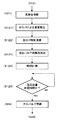
次に、図6は、泡の注出制御を行うを異なる手段で行う場合を示す第3の実施例を示すフローチャートであり、このフローチャートは、図5に示したフローチャートにおける処理ステップS20から処理ステップS24の範囲だけを示すものであり、他の処理ステップは、図5に示した処理と同様の処理を行うものである。
【0073】
この第3の実施例において、ジョッキ支持台4を移動させ、ジョッキ支持台4上に載置されたビールジョッキ50が泡ノズル2の直下に配置される(S20)と、泡の注出に先立ちオートフォーカスセンサ101aが、ビール41の注出が完了したビールジョッキ50内の液面または泡の上面までの距離を検出する(ステップS121)。オートフォーカスセンサ101aが検出した液面までの距離は制御装置7に入力され、この液面までの距離とビールジョッキ50の上縁高さとから泡が溢出しないような泡付け時間を演算する(ステップS122)。
【0074】
そして、注出バルブ駆動部12を駆動して注出タップ内に設けられた注出バルブ20を泡ノズル2からの泡の注出に切り換える(ステップS123)。この結果、注出タップの泡ノズル2から泡が注出され、ビールジョッキ50のビール41の液面上にクリーミーな泡が追加される。泡の注出が継続されることにより、ビールジョッキ50内の液面上にクリーミーな泡の量が次第に増大していくが、この間、制御装置7は、時間を計測し続け(ステップS124)、計測した時間は、継続して制御装置7に入力されている。制御装置7は、計測した時間が前記演算した泡付け時間に到達するのを待ち(ステップS125)、演算した泡付け時間に到達したときは、注出バルブ駆動部12をOFF状態に切り換えて注出バルブ20を閉鎖して泡ノズル2からの泡の注出を停止する(ステップS126)。
【0075】
【発明の効果】
以上説明したように、この発明に係る飲料ディスペンサによれば、オートフォーカスセンサと補助光源とからなる光学式距離検出手段を用い、飲用容器内に注がれる飲料の液面までの距離を検出し、制御手段がこの検出した液面までの距離に応じて台傾斜手段を制御するため、検出距離範囲が広く、正確に、かつ、配置も容器の軸線上付近より狙えることで、容器の口径を最大限生かせ、飲料の変動等環境の変動に拘わらず、飲用容器の傾斜角度の変化タイミングを従来よりも精度よく管理することができる。
【0076】
また、この発明に係る飲料ディスペンサによれば、飲料の注出の停止後に泡付けを行うため、なめらかなきめの細かいクリーミーな泡を追加することが可能であり、液体と泡との比率を所定比率に制御することが容易となる。
【0077】
また、この発明に係る飲料ディスペンサによれば、ノズルは、飲料の注出を行う飲料ノズルと泡の注出を行う泡ノズルとを有することにより、飲料の注出時の自然発泡を抑制することができる。
【図面の簡単な説明】
【図1】この発明の実施の形態に係るビールディスペンサの要部を示す図である。
【図2】図1に示したビールディスペンサを含むビール供給システムを示す図である。
【図3】図1に示したビールディスペンサの制御装置の制御ブロック図である。
【図4】第1の実施例における制御装置の処理を示すフローチャートである。
【図5】第2の実施例における制御装置の処理を示すフローチャートである。
【図6】第3の実施例における制御装置の処理を示すフローチャートである。
【符号の説明】
1 ビールディスペンサ(飲料ディスペンサ)
3 支持台駆動部(台傾斜手段)
4 ジョッキ支持台(載置台)
7 制御装置(制御手段)
12 注出バルブ駆動部
20 注出バルブ
41 ビール(飲料)
50 ジョッキ(飲用容器)
101 光学式距離検出手段
101a オートフォーカスセンサ
101b 補助光源
α 略直立位置における傾斜角度
β 傾斜位置における傾斜角度[0001]
BACKGROUND OF THE INVENTION
The present invention relates to a beverage dispenser, and more particularly to a beverage dispenser that dispenses a beverage into an inclined drinking container.
[0002]
[Prior art]
Conventionally, beverage dispensers that automatically pour beverages such as soft drinks and carbonated beverages into drinking containers such as paper cups, glasses, and mugs are known. The beverage dispenser is configured to open and close a dispensing valve provided at a dispensing outlet to which a beverage is supplied, thereby allowing a predetermined amount of beverage to be placed on a drinking container placed on a placing table disposed below the dispensing outlet. It is configured to dispense beverages.
[0003]
By the way, when a beverage is poured into a drinking container placed upright on a mounting table by such a beverage dispenser, the beverage is foamed uselessly in the drinking container, and the appearance of the beverage poured into the drinking container The impression may be impaired, or the beverage itself may be impaired. Also, in sparkling beverages such as beer and sparkling liquor, foam is also intentionally formed. Even in this case, the beverage supplied into the drinking container is directly on the surface of the beverage in the container. When poured, the foaming gas such as carbon dioxide contained in the beverage is excessively liberated, resulting in coarse foam (natural foaming). This natural foaming causes uneven beverage capacity, allowing natural foaming. It is required to reduce as much as possible.
[0004]
Therefore, in a beverage dispenser that is required to suppress excessive foaming, when a beverage is poured, the container is inclined by a predetermined angle from the upright position by the table tilting means on the table on which the drinking container is placed. In this way, the beverage supplied from the spout is poured out so as to flow downward along the inclined inner wall surface of the container. By pouring the beverage with the container tilted in this way, the dispensed beverage does not directly collide with the liquid level of the beverage in the container, so that shocking stirring is suppressed and While releasing can be suppressed, the drop which pours a drink can be made small, and this can also suppress release of foaming gas.
[0005]
On the other hand, in a beverage dispenser, after a predetermined amount of beverage has been supplied into the drinking container, the dispensing valve is automatically closed to stop the supply of the beverage and prevent the excessively supplied beverage from overflowing from the container. It is also demanded to detect the liquid level of the beverage poured into the container by the liquid level detection device and stop the supply when it reaches a predetermined position (Japanese Patent Nos. 2933530 and 2960590) Etc.) have been proposed.
[0006]
Thus, by automatically quantifying the amount of beverage dispensed, the operator of the beverage dispenser does not have to perform an operation to stop the beverage supply, so the operator is an unskilled person such as a part-time employee. However, after the operation linked to the opening of the dispensing valve, such as pressing the dispensing start button, can be kept away from the beverage dispenser. These operations can be performed in parallel, and the operation workability is improved.
[0007]
By the way, as described above, in a beverage dispenser that dispenses a beverage while tilting the drinking container, it is necessary to finally return the tilted drinking container to an upright position. This makes it easy to take out the beverage container from the beverage dispenser, and cannot supply a sufficient amount of beverage to the tilted container, and returns the container to the upright position to allow more beverage to be consumed. It is for supplying to.
[0008]
And in this type of beverage dispenser, automation is required, in this case, it is necessary to automate the operation of returning the tilted drinking container to the upright position, and in response to this request, the liquid level detection device, A technique for controlling the table tilting means to return the container to an upright position when it is detected that the bubble or liquid level of the beverage in the tilted drinking container has reached a preset position has been proposed (Patent No. 1). No. 2933369, Japanese Patent No. 2960590, etc.).
[0009]
According to this technology, after a predetermined time has elapsed since the start of the supply of beverage, by returning the inclined drinking container to an upright position, it is possible to prevent the beverage from overflowing from the inclined drinking container, Supplying a sufficient amount of beverage to the drinking container returned to the upright position, and finally detecting the liquid level of the beverage in the drinking container and stopping the supply of the beverage Makes it possible to automatically supply a fixed amount of beverage.
[0010]
[Problems to be solved by the invention]
However, as the above-described liquid level detection device, a reflection type optical sensor or an ultrasonic sensor is generally used, but has the following problems.
First, many of the reflection type optical sensors have integrated light emission / light reception, and it is necessary to emit / receive light perpendicular to the liquid surface (bubble surface) due to the straightness of light. Since the amount of light is converted into distance, there is a problem that the converted distance is likely to cause an error depending on the state of the liquid surface, and is also susceptible to disturbance light. In the case of glass, there is a problem that if the light emission / light reception is attempted vertically, the detectable distance range is very narrow and it is difficult to arrange the sensor.
[0011]
Next, there are many ultrasonic sensors with integrated transmission / reception, and it is necessary to transmit / receive perpendicularly to the liquid surface (bubble surface) due to the straightness of ultrasonic waves. In the case of a tilted container (especially a small-diameter glass), if the transmission / reception is attempted vertically, the range of the detectable distance is likely to occur. Has a problem that it is very narrow and it is difficult to arrange the sensor. In addition, in the case of an ultrasonic sensor, there is also a problem that the detection distance varies due to irregular reflection on the inner wall of the container due to its directivity.
[0012]
The present invention has been made in view of the above circumstances, and is a beverage dispenser that uses a sensor that is optimal for beverages, constantly changes the tilt angle of the drinking container in a timely manner, and eliminates the waste of the beverage that is supplied. The purpose is to obtain.
[0018]
[Means for Solving the Problems]
Beverage dispenser of this invention (Claims)1) By opening and closing the dispensing valve provided in the beverage conduit,Beverage nozzle for extracting beverage and foam nozzle for extracting foamIn a beverage dispenser that distributes and supplies a predetermined amount of beverage to a drinking container placed on a placement table disposed below the nozzle, a beverage dispensing start means for starting the dispensing of the beverage, and the above-described placement table A table tilting drive means for tilting the mounting table so that the drinking container mounted on the table is tilted from a substantially upright position to a predetermined angle position;A pair of lenses arranged at a predetermined interval on the same plane, a pair of photoarray sensors arranged at a focal length position behind the optical axis of the lenses, and an image formed on the photoarray sensor From the amount of displacementThe distance to the liquid level of the beverage poured out into the drinking containerA computing unit for computingAn optical distance detecting means comprising an autofocus sensor and an auxiliary light source; a pouring valve driving means for opening and closing the pouring valve; and a control means for controlling the table tilt driving means and the pouring valve driving means. And the control means controls the dispensing valve by driving the dispensing valve driving means by a signal from the beverage dispensing start means, and is placed on a mounting table inclined to a predetermined angular position by the table inclination driving means. The beverage is poured into the placed drinking container from the nozzle, and the table tilt driving means is driven in accordance with the detection signal from the optical distance detecting means to control the placing table to return to a substantially upright position. Stops the dispensing of the beverage from the nozzle by controlling the dispensing valve driving means according to a predetermined time or a time obtained by calculation.The distance to the liquid level after stopping the dispensing of the beverage is detected by the optical distance detection means in the previous period, and the foaming time is calculated so that the beverage does not overflow from the drinking container from the detected distance to the liquid level. When the calculated foaming time is reached, the dispensing valve is controlled to dispense the foam.Beverage dispenser characterized by stopping.
[0019]
This claim1According to the beverage dispenser according to the present invention, the predetermined time or the time obtained by calculation is used as the beverage dispensing time in a range in which the beverage poured into the drinking container does not overflow from the drinking container. Alternatively, it may be set empirically in advance, or may be a dispensing time calculated each time based on environmental changes such as temperature fluctuations.Moreover, in the drink
[0025]
DETAILED DESCRIPTION OF THE INVENTION
Hereinafter, embodiments of a beverage dispenser according to the present invention will be described in detail with reference to the drawings.
[0026]
FIG. 1 is a view showing a main part of a beer dispenser which is an embodiment of a beverage dispenser according to the present invention, FIG. 2 is an overall view of a beer supply system including the beer dispenser shown in FIG. 1, and FIG. It is a control block diagram of the control apparatus of the beer dispenser shown in FIG.
[0027]
As shown in FIG. 2, a
[0028]
The
[0029]
At the discharge end of the
[0030]
The
[0031]
[0032]
In other words, the optical distance detecting means includes a pair of lenses arranged at a predetermined interval on the same plane, and a pair of photoarray sensors arranged at a focal distance position behind the optical axis of the lens. An auto-focus sensor (AF sensor) 101a comprising: an AF module comprising: a calculation unit that calculates a distance to the object to be measured from a deviation amount of the image forming position on the photo array sensor; The auxiliary light source 101b is disposed near the distance measuring image sensor and emits a band-shaped light beam.
[0033]
The mug support 4 provided below the dispensing tap includes a substantially disc-shaped bottom plate that supports the bottom surface of the
The mug support 4 may be capable of selectively using a plurality of bottom plates having different heights according to the size of the beer mug 50 (for example, a small mug, a large mug, etc.). Moreover, it may have a bottom plate that can be raised and lowered according to the size of the
[0034]
Further, the
[0035]
Further, the
[0036]
Further, the
[0037]
Next, the 1st Example of the
First, the
[0038]
Here, the operator places an
[0039]
In response to the input of this signal, the
[0040]
Next, the
[0041]
By continuing to pour out the
[0042]
Here, the distance to the liquid level is set in advance as the amount of
[0043]
The
[0044]
The
[0045]
Even after the mug support 4 is returned to the substantially upright position, the
[0046]
In addition, the distance to the predetermined liquid surface here is set in advance as a specified amount to be poured into the
[0047]
As described above, according to the
[0048]
Moreover, according to the
[0049]
In the
[0050]
Moreover, although the
[0051]
Further, in this embodiment, the angular position at which the mug support 4 is stationary is only two positions, that is, the inclined position and the substantially upright position, but the beverage dispenser of the present invention is not limited to this form. One or more stationary tilt angle positions are set between the tilt position and the substantially upright position in the embodiment, and the tilt angle is changed according to the distance to the liquid level for each tilt angle position. Control may be performed.
[0052]
As described above, when the tilt angle is changed according to the distance to the liquid level for each of the plurality of tilt positions, the tilt angle and the distance to the liquid level indicating the timing at which the tilt angle is changed at the tilt angle are associated in advance. The attached lookup table (LUT) is set, and the
[0053]
In addition, when there are a plurality of types of
[0054]
In this embodiment, in order to eliminate the waste of the
[0055]
Next, FIG. 5 is a flowchart showing a processing flow of the
In the first embodiment, the optical distance detecting means is controlled so as to close the dispensing valve. However, in the second embodiment, according to a predetermined time or a time obtained by calculation. The dispensing
[0056]
In the flowchart of FIG. 5, first, the
[0057]
Here, the operator places an
[0058]
In response to the input of this signal, the
[0059]
Next, the
[0060]
When the dispensing of the
[0061]
Here, the distance to the liquid level is set in advance as the distance to the liquid level of the
[0062]
The support
[0063]
The
[0064]
Even after the mug support 4 is returned to the substantially upright position, the
[0065]
The predetermined time here is a time set in advance as a specified amount of time poured into the
[0066]
Here, the predetermined time or the time obtained by the calculation is the experiment or the time when the
[0067]
Next, the main body case side shaft portion that pivotally supports the mug support 4 at the upper end A is moved to the right in the illustrated horizontal direction by a mechanism (not shown), and further in conjunction with this movement, The
[0068]
When the
[0069]
By continuing to dispense the foam, the amount of creamy foam gradually increases on the liquid level in the
[0070]
Here, the predetermined time may be set experimentally or empirically in advance as the time of the
[0071]
Further, the shaft portion on the main body case side supporting the mug support 4 at the upper end A is moved in the leftward horizontal direction by a mechanism (not shown), and further in conjunction with this movement, The
[0072]
Next, FIG. 6 is a flowchart showing a third embodiment showing a case where the bubble dispensing control is performed by different means. This flowchart is a processing step from processing step S20 in the flowchart shown in FIG. Only the range of S24 is shown, and the other processing steps perform the same processing as the processing shown in FIG.
[0073]
In this third embodiment, when the mug support 4 is moved and the
[0074]
And the extraction
[0075]
【The invention's effect】
As described above, according to the beverage dispenser according to the present invention, the distance to the liquid level of the beverage poured into the drinking container is detected using the optical distance detection means including the autofocus sensor and the auxiliary light source. Since the control means controls the table tilting means according to the detected distance to the liquid level, the detection distance range is wide, accurate, and the arrangement can be aimed from the vicinity of the axis of the container. The change timing of the tilt angle of the drinking container can be managed with higher accuracy than before, regardless of the environmental change such as the maximum change and beverage fluctuation.
[0076]
Further, according to the beverage dispenser according to the present invention, since foaming is performed after stopping the dispensing of the beverage, it is possible to add smooth and fine creamy bubbles, and the ratio of the liquid to the bubbles is predetermined. It becomes easy to control the ratio.
[0077]
Moreover, according to the drink dispenser which concerns on this invention, a nozzle suppresses natural foaming at the time of the drink | pouring of a drink by having the drink nozzle which pours out a drink, and the foam nozzle which pours out a foam. Can do.
[Brief description of the drawings]
FIG. 1 is a diagram showing a main part of a beer dispenser according to an embodiment of the present invention.
FIG. 2 is a diagram showing a beer supply system including the beer dispenser shown in FIG. 1;
FIG. 3 is a control block diagram of the control device of the beer dispenser shown in FIG. 1;
FIG. 4 is a flowchart showing processing of the control device in the first embodiment.
FIG. 5 is a flowchart showing processing of a control device in the second embodiment.
FIG. 6 is a flowchart showing processing of a control device in the third embodiment.
[Explanation of symbols]
1 Beer dispenser (beverage dispenser)
3 Support stand drive (table tilting means)
4 Mug support stand (mounting stand)
7 Control device (control means)
12 Outlet valve drive
20 Dispensing valve
41 Beer (beverage)
50 mugs (drinking containers)
101 Optical distance detection means
101a Autofocus sensor
101b Auxiliary light source
α Inclination angle at almost upright position
β Inclination angle at tilt position
Claims (1)
Priority Applications (1)
| Application Number | Priority Date | Filing Date | Title |
|---|---|---|---|
| JP2002142404A JP4066713B2 (en) | 2002-05-17 | 2002-05-17 | Beverage dispenser |
Applications Claiming Priority (1)
| Application Number | Priority Date | Filing Date | Title |
|---|---|---|---|
| JP2002142404A JP4066713B2 (en) | 2002-05-17 | 2002-05-17 | Beverage dispenser |
Publications (2)
| Publication Number | Publication Date |
|---|---|
| JP2003335397A JP2003335397A (en) | 2003-11-25 |
| JP4066713B2 true JP4066713B2 (en) | 2008-03-26 |
Family
ID=29702695
Family Applications (1)
| Application Number | Title | Priority Date | Filing Date |
|---|---|---|---|
| JP2002142404A Expired - Fee Related JP4066713B2 (en) | 2002-05-17 | 2002-05-17 | Beverage dispenser |
Country Status (1)
| Country | Link |
|---|---|
| JP (1) | JP4066713B2 (en) |
Families Citing this family (3)
| Publication number | Priority date | Publication date | Assignee | Title |
|---|---|---|---|---|
| JP4524621B2 (en) * | 2005-01-04 | 2010-08-18 | 富士電機リテイルシステムズ株式会社 | Beverage dispenser control device |
| JP6501620B2 (en) * | 2015-05-29 | 2019-04-17 | 三菱重工機械システム株式会社 | Filling method and filling apparatus |
| JP2021031107A (en) * | 2019-08-23 | 2021-03-01 | ホシザキ株式会社 | Automatic beverage pouring device |
-
2002
- 2002-05-17 JP JP2002142404A patent/JP4066713B2/en not_active Expired - Fee Related
Also Published As
| Publication number | Publication date |
|---|---|
| JP2003335397A (en) | 2003-11-25 |
Similar Documents
| Publication | Publication Date | Title |
|---|---|---|
| JP2960590B2 (en) | Automatic dispensing device for sparkling beverages | |
| JP4066713B2 (en) | Beverage dispenser | |
| JP4483097B2 (en) | Beverage dispenser | |
| JP3885593B2 (en) | Beverage dispenser | |
| JP2016222326A (en) | Beverage automatic spouting device | |
| JP3606622B2 (en) | Automatic quantitative dispensing device for sparkling beverages | |
| JP2003226399A (en) | Drink dispenser | |
| JP2933369B2 (en) | Automatic dispensing device for sparkling beverages | |
| JP3885592B2 (en) | Beverage dispenser | |
| JP4569009B2 (en) | Beverage dispenser | |
| JPH0646876Y2 (en) | Automatic beverage dispenser | |
| JP2933530B2 (en) | Automatic dispensing device for sparkling beverages | |
| JP4507415B2 (en) | Beverage dispenser | |
| JP4483120B2 (en) | Beverage dispenser | |
| JP2933370B2 (en) | Automatic dispensing device for sparkling beverages | |
| JP2020075736A (en) | Drink automatic spouting device | |
| JP2002234595A (en) | Beverage dispenser | |
| JP7336096B2 (en) | beverage dispenser | |
| JP2003221096A (en) | Beverage dispenser | |
| JP2005263305A (en) | Beverage dispenser | |
| JP6721292B2 (en) | Effervescent beverage automatic dispenser | |
| JP6577755B2 (en) | Beverage automatic dispensing device | |
| JP2933371B2 (en) | Automatic dispensing device for sparkling beverages | |
| JP2933372B2 (en) | Automatic dispensing device for sparkling beverages | |
| JP2020075742A (en) | Drink automatic spouting device |
Legal Events
| Date | Code | Title | Description |
|---|---|---|---|
| A621 | Written request for application examination |
Free format text: JAPANESE INTERMEDIATE CODE: A621 Effective date: 20040914 |
|
| RD02 | Notification of acceptance of power of attorney |
Free format text: JAPANESE INTERMEDIATE CODE: A7422 Effective date: 20060703 |
|
| RD04 | Notification of resignation of power of attorney |
Free format text: JAPANESE INTERMEDIATE CODE: A7424 Effective date: 20060704 |
|
| A977 | Report on retrieval |
Free format text: JAPANESE INTERMEDIATE CODE: A971007 Effective date: 20061211 |
|
| A131 | Notification of reasons for refusal |
Free format text: JAPANESE INTERMEDIATE CODE: A131 Effective date: 20070220 |
|
| A521 | Written amendment |
Free format text: JAPANESE INTERMEDIATE CODE: A523 Effective date: 20070423 |
|
| TRDD | Decision of grant or rejection written | ||
| A01 | Written decision to grant a patent or to grant a registration (utility model) |
Free format text: JAPANESE INTERMEDIATE CODE: A01 Effective date: 20071218 |
|
| A61 | First payment of annual fees (during grant procedure) |
Free format text: JAPANESE INTERMEDIATE CODE: A61 Effective date: 20071231 |
|
| FPAY | Renewal fee payment (event date is renewal date of database) |
Free format text: PAYMENT UNTIL: 20110118 Year of fee payment: 3 |
|
| R150 | Certificate of patent or registration of utility model |
Free format text: JAPANESE INTERMEDIATE CODE: R150 |
|
| FPAY | Renewal fee payment (event date is renewal date of database) |
Free format text: PAYMENT UNTIL: 20110118 Year of fee payment: 3 |
|
| FPAY | Renewal fee payment (event date is renewal date of database) |
Free format text: PAYMENT UNTIL: 20120118 Year of fee payment: 4 |
|
| FPAY | Renewal fee payment (event date is renewal date of database) |
Free format text: PAYMENT UNTIL: 20130118 Year of fee payment: 5 |
|
| FPAY | Renewal fee payment (event date is renewal date of database) |
Free format text: PAYMENT UNTIL: 20130118 Year of fee payment: 5 |
|
| S531 | Written request for registration of change of domicile |
Free format text: JAPANESE INTERMEDIATE CODE: R313531 |
|
| FPAY | Renewal fee payment (event date is renewal date of database) |
Free format text: PAYMENT UNTIL: 20130118 Year of fee payment: 5 |
|
| R350 | Written notification of registration of transfer |
Free format text: JAPANESE INTERMEDIATE CODE: R350 |
|
| FPAY | Renewal fee payment (event date is renewal date of database) |
Free format text: PAYMENT UNTIL: 20130118 Year of fee payment: 5 |
|
| S111 | Request for change of ownership or part of ownership |
Free format text: JAPANESE INTERMEDIATE CODE: R313111 |
|
| FPAY | Renewal fee payment (event date is renewal date of database) |
Free format text: PAYMENT UNTIL: 20130118 Year of fee payment: 5 |
|
| R350 | Written notification of registration of transfer |
Free format text: JAPANESE INTERMEDIATE CODE: R350 |
|
| FPAY | Renewal fee payment (event date is renewal date of database) |
Free format text: PAYMENT UNTIL: 20130118 Year of fee payment: 5 |
|
| FPAY | Renewal fee payment (event date is renewal date of database) |
Free format text: PAYMENT UNTIL: 20140118 Year of fee payment: 6 |
|
| R250 | Receipt of annual fees |
Free format text: JAPANESE INTERMEDIATE CODE: R250 |
|
| R250 | Receipt of annual fees |
Free format text: JAPANESE INTERMEDIATE CODE: R250 |
|
| R250 | Receipt of annual fees |
Free format text: JAPANESE INTERMEDIATE CODE: R250 |
|
| LAPS | Cancellation because of no payment of annual fees |