JP4065178B2 - Multi-plate friction clutch - Google Patents
Multi-plate friction clutch Download PDFInfo
- Publication number
- JP4065178B2 JP4065178B2 JP2002309678A JP2002309678A JP4065178B2 JP 4065178 B2 JP4065178 B2 JP 4065178B2 JP 2002309678 A JP2002309678 A JP 2002309678A JP 2002309678 A JP2002309678 A JP 2002309678A JP 4065178 B2 JP4065178 B2 JP 4065178B2
- Authority
- JP
- Japan
- Prior art keywords
- clutch
- disc spring
- holding groove
- friction
- plate
- Prior art date
- Legal status (The legal status is an assumption and is not a legal conclusion. Google has not performed a legal analysis and makes no representation as to the accuracy of the status listed.)
- Expired - Lifetime
Links
Images


Classifications
-
- F—MECHANICAL ENGINEERING; LIGHTING; HEATING; WEAPONS; BLASTING
- F16—ENGINEERING ELEMENTS AND UNITS; GENERAL MEASURES FOR PRODUCING AND MAINTAINING EFFECTIVE FUNCTIONING OF MACHINES OR INSTALLATIONS; THERMAL INSULATION IN GENERAL
- F16D—COUPLINGS FOR TRANSMITTING ROTATION; CLUTCHES; BRAKES
- F16D25/00—Fluid-actuated clutches
- F16D25/06—Fluid-actuated clutches in which the fluid actuates a piston incorporated in, i.e. rotating with the clutch
- F16D25/062—Fluid-actuated clutches in which the fluid actuates a piston incorporated in, i.e. rotating with the clutch the clutch having friction surfaces
- F16D25/063—Fluid-actuated clutches in which the fluid actuates a piston incorporated in, i.e. rotating with the clutch the clutch having friction surfaces with clutch members exclusively moving axially
- F16D25/0635—Fluid-actuated clutches in which the fluid actuates a piston incorporated in, i.e. rotating with the clutch the clutch having friction surfaces with clutch members exclusively moving axially with flat friction surfaces, e.g. discs
- F16D25/0638—Fluid-actuated clutches in which the fluid actuates a piston incorporated in, i.e. rotating with the clutch the clutch having friction surfaces with clutch members exclusively moving axially with flat friction surfaces, e.g. discs with more than two discs, e.g. multiple lamellae
Landscapes
- Engineering & Computer Science (AREA)
- General Engineering & Computer Science (AREA)
- Mechanical Engineering (AREA)
- Hydraulic Clutches, Magnetic Clutches, Fluid Clutches, And Fluid Joints (AREA)
Description
【0001】
【発明の属する技術分野】
本発明は、クラッチアウタと、このクラッチアウタに囲繞されるクラッチインナと、クラッチアウタに軸方向摺動可能にスプライン嵌合される複数枚の第1摩擦板と、これら第1摩擦板と交互に重ねられてクラッチインナに軸方向摺動可能にスプライン嵌合される複数枚の第2摩擦板と、この第1及び第2摩擦板群の一側面に対向してクラッチアウタに固定される受圧板と、クラッチアウタに嵌装され、第1及び第2摩擦板群を受圧板に向かって押圧すべく油圧作動し得るクラッチピストンとを備え、クラッチピストンの、第1及び第2摩擦板群に対する加圧面に環状の保持溝を形成し、この保持溝に、第1及び第2摩擦板群に弾発的に当接可能な緩衝用皿ばねを収容してなる多板摩擦式クラッチの改良に関する。
【0002】
【従来の技術】
かゝる多板摩擦式クラッチは、下記特許文献1に開示されているように、既に知られている。
【0003】
【特許文献1】
特開平4−341652号公報
【0004】
【発明が解決しようとする課題】
従来のかゝる多板摩擦式クラッチでは、クラッチピストンの保持溝への皿ばねの挿入を容易にすべく、保持溝の内周面がクラッチピストンと同軸の円筒面に形成されている。
【0005】
こうした従来の多板摩擦式クラッチでは、クラッチピストンの不作動状態におけるクラッチピストン及び受圧板間の総合間隙が、皿ばねの保持溝からの脱落を防ぐように設定されている。
【0006】
しかしながら、クラッチの遮断状態での引きずりを回避するために、隣り合う摩擦板間の間隙を一定値以下に狭めることはできないから、クラッチのトルク容量を増加すべく、摩擦板の枚数を増やす場合には、クラッチピストン及び受圧板間の総合間隙を、皿ばねの離脱を防ぐ範囲に抑えることが困難となることがある。
【0007】
本発明は、かゝる事情に鑑みてなされたもので、摩擦板の枚数を増やす場合でも、皿ばねの脱落を考慮することなく、クラッチピストン及び受圧板間の総合間隙を自由に設定し得るようにした前記多板摩擦式クラッチを提供することを目的とする。
【0008】
【課題を解決するための手段】
上記目的を達成するために、本発明は、クラッチアウタと、このクラッチアウタに囲繞されるクラッチインナと、クラッチアウタに軸方向摺動可能にスプライン嵌合される複数枚の第1摩擦板と、これら第1摩擦板と交互に重ねられてクラッチインナに軸方向摺動可能にスプライン嵌合される複数枚の第2摩擦板と、この第1及び第2摩擦板群の一側面に対向してクラッチアウタに固定される受圧板と、クラッチアウタに嵌装され、第1及び第2摩擦板群を受圧板に向かって押圧すべく油圧作動し得るクラッチピストンとを備え、クラッチピストンの、第1及び第2摩擦板群に対する加圧面に環状の保持溝を形成し、この保持溝に、外周端部が第1及び第2摩擦板群に弾発的に当接可能な緩衝用皿ばねの内周端部を収容してなる多板摩擦式クラッチにおいて、前記保持溝の軸方向深さを、前記皿ばねの内周端部の板厚よりも大きく設定し、前記保持溝の軸方向開口縁には、前記皿ばねの内 周端部に対し該ばねの軸線方向外側から係合して該皿ばねの保持溝からの離脱を阻止する環状突起を、該保持溝の内面より径方向外向きに突出させて形成したことを第1の特徴とし、また本発明は、クラッチアウタと、このクラッチアウタに囲繞されるクラッチインナと、クラッチアウタに軸方向摺動可能にスプライン嵌合される複数枚の第1摩擦板と、これら第1摩擦板と交互に重ねられてクラッチインナに軸方向摺動可能にスプライン嵌合される複数枚の第2摩擦板と、この第1及び第2摩擦板群の一側面に対向してクラッチアウタに固定される受圧板と、クラッチアウタに嵌装され、第1及び第2摩擦板群を受圧板に向かって押圧すべく油圧作動し得るクラッチピストンとを備え、クラッチピストンの、第1及び第2摩擦板群に対する加圧面に環状の保持溝を形成し、この保持溝に、内周端部が第1及び第2摩擦板群に弾発的に当接可能な緩衝用皿ばねの外周端部を収容してなる多板摩擦式クラッチにおいて、前記保持溝の軸方向深さを、前記皿ばねの外周端部の板厚よりも大きく設定し、前記保持溝の軸方向開口縁には、前記皿ばねの外周端部に対し該ばねの軸線方向外側から係合して該皿ばねの保持溝からの離脱を阻止する環状突起を、該保持溝の内面より径方向内向きに突出させて形成したことを第2の特徴とする。
【0009】
この第1,第2の各特徴によれば、クラッチの遮断状態においても、皿ばねは、環状突起により保持溝からの離脱を阻止されるので、クラッチのトルク容量を増大を図るべく、第1及び第2摩擦板の枚数を増加する場合、クラッチピストン及び受圧板間の総合間隙が皿ばねの軸方向長さより大きくなっても支障はない。したがって、皿ばねの脱落を考慮することなく、各摩擦板の枚数を自由に増加させることが可能となり、クラッチのトルク容量の増大を容易に図ることができる。
【0010】
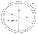
また本発明は、第1の特徴に加えて、前記皿ばねは、自由状態で楕円形に形成されていて、それの自由状態での内短径をDa、内長径をDbとし、また前記環状突起先端の外径をDpとしたとき、Da<Dp<Dbの関係に設定され、且つその皿ばねを略真円に弾性変形したときは、該皿ばねの内径が前記環状突起先端の外径より大きくなって、該環状突起に干渉されずに該皿ばねの前記保持溝への挿入を可能にしたことを第3の特徴とし、また第2の特徴に加えて、前記皿ばねは、自由状態で楕円形に形成されていて、それの自由状態での外短径をDa′、外長径をDb′とし、また前記環状突起先端の内径をDp′としたとき、Da′<Dp′<Db′の関係に設定され、且つその皿ばねを略真円に弾性変形したときは、該皿ばねの外径が前記環状突起先端の内径より小さくなって、該環状突起に干渉されずに該皿ばねの前記保持溝への挿入を可能にしたことを第4の特徴とする。
【0011】
この第3,第4の各特徴によれば、保持溝に、皿ばねの離脱防止のための環状突起が設けられているにも拘らず、皿ばねを保持溝に容易に装着することができ、その装着後、離脱防止のための後加工が不要であり、したがって組立性が良好であると共に、加工工程の増加を抑えることができ、コストの低減に寄与し得る。
【0012】
【発明の実施の形態】
本発明の実施の形態を、添付図面に示す本発明の好適な実施例に基づいて以下に説明する。
【0013】
図1は本発明の一実施例に係る多板摩擦式クラッチの縦断面図、図2は図1の2部拡大図、図3は図1及び図2中の皿ばねの平面図、図4は本発明の別の実施例を示す図2との対応図、図5は本発明の更に別の実施例を示す図1との対応図、図6は図5の6部拡大図、図7は図5及び図6中の皿ばねの平面図である。
【0014】
先ず、図1において、符号Cは自動車の自動変速機用多板摩擦式クラッチを示す。このクラッチCのクラッチアウタ1は、端壁部2の外周端に円筒部3を、その内周端にハブ4をそれぞれ連設して構成され、そのハブ4は入力軸5にスプライン結合される。入力軸5上には、駆動ギヤ7を一体に備えた出力軸6が相対回転自在に支承され、この出力軸6に一体に連なるクラッチインナ8が前記円筒部3内に同心状に配置される。
【0015】
前記円筒部3の内周面及びハブ4の外周面には、端壁部2との間に油圧室11を画成するクラッチピストン10が一対のシール部材24,25を介して摺動可能に嵌装され、このクラッチピストン10とハブ4との間に、クラッチピストン10を油圧室11側へ付勢する戻しばね12が縮設される。ハブ4には、油圧室11に連なる作動油給排孔13が設けられる。
【0016】
前記円筒部3の内周面には、また、複数枚の第1摩擦板14がクラッチピストン10の外側に隣接して摺動可能にスプライン嵌合され、これら第1摩擦板14と交互に重なるように配置される複数枚の第2摩擦板15がクラッチインナ8の外周面に摺動可能にスプライン嵌合される。第1摩擦板14は鋼板製であり、第2摩擦板15は、鋼板製の芯板18の両側面に摩擦ライニング19を接着して構成される。
【0017】
さらに最外側の第2摩擦板15の外側面に対向する受圧板16が前記円筒部3にスプライン嵌合され、この受圧板16は円筒部3に係止された止め環17により軸方向外方への移動が阻止される。
【0018】
クラッチピストン10と、それに隣接する第1摩擦板14との間には緩衝用の皿ばね20が介装される。
【0019】
図2及び図3に示すように、上記皿ばね20は、クラッチピストン10側から第1摩擦板14側に向かって大径となる截頭円錐形をなしている。この皿ばね20は、その内周端部が、クラッチピストン10の、第1摩擦板14に対向する加圧面10aに形成された環状の保持溝21に収容されると共に、その外周端部が上記加圧面10aより突出し所定の間隙を存して第1摩擦板14に対向するように配置される。そして、保持溝21の軸方向開口縁には、皿ばね20の内周端部外側面に対向すべく保持溝21の内面より半径方向外向きに突出する環状突起22が形成される。従って、この環状突起22が皿ばね20の内周端部に該ばね20の軸線方向外側(図2で右側)から係合することにより、皿ばね20の保持溝21からの離脱が阻止される。図示例では、その環状突起22は、保持溝21の内側面を逆テーパ状に切削加工することにより形成される。
【0020】
このような環状突起22付きの保持溝21への皿ばね20の取り付けを容易にするために、皿ばね20は次のような構成を有する。
【0021】
即ち、皿ばね20は、自由状態で楕円形を呈するように成形される。その際、皿ばね20の内短径をDa、内長径をDb、前記環状突起22の先端の外径をDpとしたとき、
Da<Dp<Db
上記不等式を満足させ、且つ皿ばね20を略真円に弾性変形したときは、皿ばね20の内径が環状突起22の先端の外径Dpより大きくなるようになっている。
【0022】
次に、この実施例の作用について説明する。
【0023】
クラッチCの油圧室11に作動油圧を供給すれば、その油圧を受けたクラッチピストン10は、戻しばね12の荷重に抗して前進し、皿ばね20を介して第1及び第2摩擦板14,15群を受圧板16に対して押圧する。そのとき、クラッチピストン10から受圧板16までに存在する各隣接する第1及び第2摩擦板14,15間の間隙が排除され、次いで皿ばね20が軸方向に圧縮され、その圧縮荷重の増加に応じて第1及び第2摩擦板14,15間の摩擦力が増加していくことで、クラッチアウタ1及びクラッチインナ8間、即ち入力軸5及び出力軸6間の動力伝達を緩徐に開始することができる。そして、皿ばね20が保持溝21内に押し込まれると、クラッチピストン10の加圧面10aが第1及び第2摩擦板14,15群を直接押圧することになるので、第1及び第2摩擦板14,15間の摩擦力は最大となって、入力軸5及び出力軸6間での高トルクの伝達を可能にする。
【0024】
油圧室11から油圧を解放すれば、クラッチピストン10は、戻しばね12の反発力により後退して、皿ばね20や各第1及び第2摩擦板14,15を自由にするので、入力軸5及び出力軸6間の動力伝達は遮断される。
【0025】
このようなクラッチCの遮断状態においても、皿ばね20は、保持溝21の環状突起22により保持溝21からの離脱を阻止されるので、クラッチCのトルク容量を増大を図るべく、第1及び第2摩擦板14,15の枚数を増加する場合、それに伴ないクラッチピストン10及び受圧板16間の総合間隙が皿ばね20の軸方向長さより大きくなっても支障はない。したがって、皿ばね20の脱落を考慮することなく、各摩擦板14,15の枚数を自由に増加させることが可能となり、クラッチCのトルク容量の増大を容易に図ることができる。
【0026】
ところで、クラッチピストン10の保持溝21への皿ばね20の取り付けに当たっては、先ず、例えば楕円形の皿ばね20の長径側において、半径方向内向きの荷重を加えて皿ばね20を略真円に弾性変形させ、これにより皿ばね20の内径を保持溝21の環状突起22の先端の外径Dpより大きくする。そこで、皿ばね20内に環状突起22を通過させた後、皿ばね20から変形荷重を解放すれば、皿ばね20は元の楕円形に復帰して、その内短径Daを環状突起22の先端の外径Dpより小さくするため、この環状突起22により皿ばね20の保持溝21からの離脱が阻止される。
【0027】
また別の取り付け方法としては、皿ばね20の短径側の一端部を保持溝21に引っ掛けてから、その他端側を引っ張れば、皿ばね20は略真円となって、皿ばね20の他の部分も、環状突起22に邪魔されることなく、保持溝21に収めることができる。
【0028】
このように、保持溝21に、皿ばね20の離脱防止のための環状突起22が設けられているにも拘らず、皿ばね20を保持溝21に容易に装着することができ、その装着後、離脱防止のための後加工が不要である。したがって組立性が良好であると共に、加工工程の増加を抑えることができ、コストの低減に寄与し得る。
【0029】
図4は、本発明の別に実施例を示すもので、クラッチピストン10の保持溝21の開口縁に、皿ばね20の離脱を防ぐ環状突起22をかしめ加工により形成した点を除けば、前実施例と同様の構成であり、その作用効果においても変わりがない。したがって、図4中、前実施例と対応する部分には、それと同一の参照符号を付して、その説明を省略する。
【0030】
最後に、図5〜図7に示す本発明の更に別の実施例について説明する。
【0031】
この実施例では、皿ばね20は、クラッチピストン10側から第1摩擦板14側に向かって小径となる截頭円錐形をなしており、その外周端部がクラッチピストン10の保持溝21′に収容され、その内周端部がクラッチピストン10の加圧面10aより突出し所定の間隙を存して第1摩擦板14に対向するように配置される。保持溝21′の軸方向開口縁には、皿ばね20の外周端部外側面に対向すべく保持溝21の内面より半径方向内向きに突出する環状突起22′が形成される。従って、この環状突起22′が皿ばね20の外周端部に該ばね20の軸線方向外側(図6で右側)から係合することにより、皿ばね20の保持溝21′からの離脱が阻止される。
【0032】
皿ばね20は、前実施例と同様に自由状態で楕円形を呈しており、それの外短径をDa′、外長径をDb′、環状突起22′の先端の内径をDp′としたとき、
Da′<Dp′<Db′
上記不等式を満足させ、且つ皿ばね20を略真円に弾性変形したときは、皿ばね20の外径が環状突起22′の先端の内径Dpより小さくなるようになっている。
【0033】
したがって、楕円形の皿ばね20を略真円に弾性変形させれば、その外周端部を環状突起22に干渉されることなく保持溝21′内に挿入することができる。その挿入後、皿ばね20を楕円形に復形させれば、その外長径Dbは環状突起22′の先端の内径Dp′より大きくなるため、この環状突起22′により皿ばね20の保持溝21′からの離脱が阻止される。
【0034】
その他の構成は前実施例と同様であるので、図5〜図7中、前実施例と対応する部分には同一の参照符号を付して、その説明を省略する。
【0035】
本発明は、前記実施例に限定されるものではなく、その要旨の範囲内で自由に設計変更が可能である。例えば、環状突起22,22′としては、複数の突起を環状に配列して構成することもできる。
【0036】
【発明の効果】
以上のように本発明の第1,第2の各特徴によれば、多板摩擦式クラッチにおいて、前記保持溝の軸方向開口縁に、前記皿ばねの周端部に該ばねの軸方向外側から係合して該皿ばねの保持溝からの離脱を阻止する環状突起を形成したので、クラッチのトルク容量を増大を図るべく、第1及び第2摩擦板の枚数を増加する場合、それに伴ないクラッチピストン及び受圧板間の総合間隙が皿ばねの軸方向長さより大きくなっても、皿ばねが保持溝から離脱することはなく、支障がない。したがって、皿ばねの脱落を考慮することなく、各摩擦板の枚数を自由に増加させることが可能となり、クラッチのトルク容量の増大を容易に図ることができる。
【0037】
また本発明の第3,第4の各特徴によれば、前記皿ばねを自由状態で楕円形に形成して、該皿ばねを略真円に弾性変形したとき前記環状突起に干渉されずに該皿ばねの前記保持溝への挿入を可能にしたので、保持溝に、皿ばねの離脱防止のための環状突起が設けられているにも拘らず、皿ばねを保持溝に容易に装着することができ、その装着後、離脱防止のための後加工が不要であり、したがって組立性が良好であると共に、加工工程の増加を抑えることができ、コストの低減に寄与し得る。
【図面の簡単な説明】
【図1】 本発明の一実施例に係る多板摩擦式クラッチの縦断面図
【図2】 図1の2部拡大図
【図3】 図1及び図2中の皿ばねの平面図
【図4】 本発明の別の実施例を示す図2との対応図
【図5】 本発明の更に別の実施例を示す図1との対応図
【図6】 図5の6部拡大図
【図7】 図5及び図6中の皿ばねの平面図
【符号の説明】
C・・・・クラッチ
1・・・・クラッチアウタ
8・・・・クラッチインナ
10・・・クラッチピストン
14・・・第1摩擦板
15・・・第2摩擦板
16・・・受圧板
20・・・皿ばね
21・・・保持溝
21′・・保持溝
22・・・環状突起
22′・・環状突起[0001]
BACKGROUND OF THE INVENTION
The present invention includes a clutch outer, a clutch inner surrounded by the clutch outer, a plurality of first friction plates that are spline fitted to the clutch outer so as to be axially slidable, and the first friction plates alternately. A plurality of second friction plates that are overlapped and are spline-fitted to the clutch inner so as to be axially slidable, and a pressure receiving plate that is fixed to the clutch outer so as to face one side of the first and second friction plate groups And a clutch piston that is fitted to the clutch outer and can be hydraulically operated to press the first and second friction plate groups toward the pressure receiving plate, and the clutch piston is applied to the first and second friction plate groups. The present invention relates to an improvement of a multi-plate friction clutch in which an annular holding groove is formed on the pressure surface, and a buffer disc spring that can elastically contact the first and second friction plate groups is accommodated in the holding groove.
[0002]
[Prior art]
Such a multi-plate friction clutch is already known as disclosed in
[0003]
[Patent Document 1]
Japanese Patent Laid-Open No. 4-341651
[Problems to be solved by the invention]
In such a conventional multi-plate friction clutch, the inner peripheral surface of the holding groove is formed on a cylindrical surface coaxial with the clutch piston so that the disc spring can be easily inserted into the holding groove of the clutch piston.
[0005]
In such a conventional multi-plate friction clutch, the total gap between the clutch piston and the pressure receiving plate when the clutch piston is in an inoperative state is set so as to prevent the disc spring from dropping from the holding groove.
[0006]
However, in order to avoid dragging when the clutch is disengaged, the gap between adjacent friction plates cannot be reduced below a certain value, so when increasing the number of friction plates in order to increase the torque capacity of the clutch. In this case, it may be difficult to keep the total gap between the clutch piston and the pressure receiving plate within a range that prevents the disc spring from being detached.
[0007]
The present invention has been made in view of such circumstances, and even when the number of friction plates is increased, the total gap between the clutch piston and the pressure receiving plate can be freely set without considering the falling off of the disc spring. An object of the present invention is to provide the multi-plate friction clutch.
[0008]
[Means for Solving the Problems]
To achieve the above object, the present invention provides a clutch outer, a clutch inner surrounded by the clutch outer, a plurality of first friction plates spline-fitted to the clutch outer so as to be axially slidable, A plurality of second friction plates that are alternately overlapped with the first friction plates and are spline-fitted to the clutch inner so as to be axially slidable, and facing one side of the first and second friction plate groups A pressure receiving plate fixed to the clutch outer, and a clutch piston fitted to the clutch outer and hydraulically operable to press the first and second friction plate groups toward the pressure receiving plate. An annular holding groove is formed on the pressing surface for the second friction plate group, and an outer end of the buffer spring that can elastically contact the first and second friction plate groups in the holding groove . multi-plate friction type click made by housing a peripheral edge portion In pitch, the axial depth of the retaining groove, said set larger than the thickness of the inner peripheral edge portion of the disc spring, in the axial opening edge of the retaining groove, the inner peripheral end of the disc spring On the other hand, an annular protrusion that engages from the outside in the axial direction of the spring and prevents the disc spring from being detached from the holding groove is formed by projecting radially outward from the inner surface of the holding groove . The present invention is characterized in that a clutch outer, a clutch inner surrounded by the clutch outer, a plurality of first friction plates spline-fitted to the clutch outer so as to be axially slidable, A plurality of second friction plates that are alternately overlapped with the friction plates and are spline-fitted to the clutch inner so as to be axially slidable, and facing the one side of the first and second friction plate groups to the clutch outer A pressure receiving plate to be fixed and a clutch outer, And a clutch piston that can be hydraulically operated to press the second friction plate group toward the pressure receiving plate, and an annular holding groove is formed on the pressure surface of the clutch piston with respect to the first and second friction plate groups. In a multi-plate friction clutch in which a holding groove accommodates an outer peripheral end portion of a buffering disc spring whose inner peripheral end portion can elastically contact the first and second friction plate groups, The axial depth is set larger than the plate thickness of the outer peripheral end of the disc spring, and the axial opening edge of the holding groove is engaged with the outer peripheral end of the disc spring from the outer side in the axial direction of the spring. The second feature is that an annular protrusion that prevents the disc spring from being detached from the holding groove is formed to protrude radially inward from the inner surface of the holding groove.
[0009]
According to the first and second features, even when the clutch is disengaged, the disc spring is prevented from being detached from the holding groove by the annular projection, so that the first torque torque capacity of the clutch can be increased. When the number of the second friction plates is increased, there is no problem even if the total gap between the clutch piston and the pressure receiving plate is larger than the axial length of the disc spring. Therefore, it is possible to freely increase the number of friction plates without considering the falling of the disc spring, and the torque capacity of the clutch can be easily increased.
[0010]
According to the present invention, in addition to the first feature, the disc spring is formed in an elliptical shape in a free state, and an inner minor axis is Da and an inner major axis is Db in the free state. When the outer diameter of the protrusion tip is Dp, the relationship of Da <Dp <Db is set, and when the disc spring is elastically deformed to a substantially perfect circle, the inner diameter of the disc spring is the outer diameter of the annular projection tip. becomes larger, that enables insertion into the holding groove of the dish spring without interference to the annular projection and the third feature, also in addition to the second feature, the disc spring is free When the outer short diameter in the free state is Da ′, the outer long diameter is Db ′, and the inner diameter of the tip of the annular protrusion is Dp ′, Da ′ <Dp ′ < When the disc spring is elastically deformed to a substantially perfect circle, the outer diameter of the disc spring is set. The annular projecting tip is smaller than the inner diameter of the fourth feature in that to allow insertion into the holding groove of the dish spring without interfering with the annular protrusion.
[0011]
According to the third and fourth features, the disc spring can be easily mounted in the holding groove even though the holding groove is provided with an annular projection for preventing the disc spring from being detached. After the mounting, post-processing for preventing detachment is unnecessary, so that the assembling property is good, the increase in the processing steps can be suppressed, and the cost can be reduced.
[0012]
DETAILED DESCRIPTION OF THE INVENTION
Embodiments of the present invention will be described below on the basis of preferred embodiments of the present invention shown in the accompanying drawings.
[0013]
1 is a longitudinal sectional view of a multi-plate friction clutch according to an embodiment of the present invention, FIG. 2 is an enlarged view of a
[0014]
First, in FIG. 1, the code | symbol C shows the multi-plate friction type clutch for automatic transmissions of a motor vehicle. The clutch outer 1 of the clutch C is configured by connecting a
[0015]
The
[0016]
A plurality of
[0017]
Further, a
[0018]
A
[0019]
As shown in FIGS. 2 and 3, the
[0020]
In order to facilitate the attachment of the
[0021]
That is, the
Da <Dp <Db
When the above inequality is satisfied and the
[0022]
Next, the operation of this embodiment will be described.
[0023]
When the hydraulic pressure is supplied to the
[0024]
When the hydraulic pressure is released from the
[0025]
Even in such a disengaged state of the clutch C, the
[0026]
By the way, when attaching the
[0027]
As another attachment method, if one end of the short diameter side of the
[0028]
Thus, although the holding
[0029]
FIG. 4 shows another embodiment of the present invention, which is the previous embodiment except that an
[0030]
Finally, still another embodiment of the present invention shown in FIGS. 5 to 7 will be described.
[0031]
In this embodiment, the
[0032]
Da ′ <Dp ′ <Db ′
To satisfy the above inequality, and when elastically deformed into a substantially true
[0033]
Therefore, if the
[0034]
Since other configurations are the same as those of the previous embodiment, portions corresponding to those of the previous embodiment are denoted by the same reference numerals in FIGS.
[0035]
The present invention is not limited to the above-described embodiments, and can be freely modified within the scope of the gist thereof. For example, the
[0036]
【The invention's effect】
As described above, according to the first and second features of the present invention, in the multi- plate friction clutch, the axially outer side of the spring is formed on the axial opening edge of the holding groove and on the peripheral end of the disc spring. When the number of the first and second friction plates is increased in order to increase the torque capacity of the clutch, an annular protrusion that prevents the disc spring from being detached from the holding groove is formed. Even if the total gap between the clutch piston and the pressure receiving plate which is not larger than the axial length of the disc spring, the disc spring will not be detached from the holding groove, and there will be no trouble. Therefore, it is possible to freely increase the number of friction plates without considering the falling of the disc spring, and the torque capacity of the clutch can be easily increased.
[0037]
According to the third and fourth features of the present invention, the disc spring is formed in an elliptical shape in a free state, and when the disc spring is elastically deformed into a substantially perfect circle, it is not interfered with the annular projection. Since the disc spring can be inserted into the holding groove, the disc spring is easily mounted in the holding groove even though the holding groove is provided with an annular protrusion for preventing the disc spring from being detached. After installation, post-processing for preventing detachment is unnecessary, so that the assemblability is good and an increase in processing steps can be suppressed, which can contribute to cost reduction.
[Brief description of the drawings]
FIG. 1 is a longitudinal sectional view of a multi-plate friction clutch according to an embodiment of the present invention. FIG. 2 is an enlarged view of
C ...
Claims (4)
前記保持溝(21)の軸方向深さを、前記皿ばね(20)の内周端部の板厚よりも大きく設定し、
前記保持溝(21)の軸方向開口縁には、前記皿ばね(20)の内周端部に対し該ばね(20)の軸線方向外側から係合して該皿ばね(20)の保持溝(21)からの離脱を阻止する環状突起(22)を、該保持溝(21)の内面より径方向外向きに突出させて形成したことを特徴とする多板摩擦式クラッチ。A clutch outer (1), a clutch inner (8) surrounded by the clutch outer (1), and a plurality of first friction plates (14) spline-fitted to the clutch outer (1) so as to be axially slidable ), A plurality of second friction plates (15) that are alternately stacked with these first friction plates (14) and are spline-fitted to the clutch inner (8) so as to be axially slidable, A pressure receiving plate (16) fixed to the clutch outer (1) facing one side of the second friction plate (14, 15) group, and fitted to the clutch outer (1), and the first and second friction plates A clutch piston (10) that can be hydraulically operated to press the (14, 15) group toward the pressure receiving plate (16), and the first and second friction plates (14, 15) of the clutch piston (10). an annular holding groove in pressing surface (10a) with respect to the group (2 1 Forming a inner peripheral end of the holding groove (2 1), the outer peripheral end portion first and second friction plates (14, 15) resiliently contactable buffer belleville spring group (20) In the multi-plate friction clutch containing the part ,
The axial depth of the holding groove (21) is set larger than the plate thickness of the inner peripheral end of the disc spring (20),
Wherein the axial opening edge of the retaining groove (2 1), held by the disc spring (20) in engagement with the dish spring from the axial direction outside of the spring relative to the inner peripheral edge portion (20) (20) A multi-plate friction clutch characterized in that an annular protrusion (2 2 ) for preventing separation from the groove (2 1 ) is formed to protrude radially outward from the inner surface of the holding groove (21) .
前記保持溝(21′)の軸方向深さを、前記皿ばね(20)の外周端部の板厚よりも大きく設定し、An axial depth of the holding groove (21 ′) is set larger than a plate thickness of an outer peripheral end portion of the disc spring (20),
前記保持溝(21′)の軸方向開口縁には、前記皿ばね(20)の外周端部に対し該ばね(20)の軸線方向外側から係合して該皿ばね(20)の保持溝(21′)からの離脱を阻止する環状突起(22′)を、該保持溝(21′)の内面より径方向内向きに突出させて形成したことを特徴とする多板摩擦式クラッチ。The holding groove of the disc spring (20) is engaged with the outer circumferential end of the disc spring (20) from the outside in the axial direction at the axial opening edge of the holding groove (21 '). A multi-plate friction clutch characterized in that an annular protrusion (22 ') for preventing separation from (21') is formed to protrude radially inward from the inner surface of the holding groove (21 ').
前記皿ばね(20)は、自由状態で楕円形に形成されていて、それの自由状態での内短径をDa、内長径をDbとし、また前記環状突起(22)先端の外径をDpとしたとき、 Da<Dp<Dbの関係に設定され、且つ
その皿ばね(20)を略真円に弾性変形したときは、該皿ばね(20)の内径が前記環状突起(22)先端の外径(Dp)より大きくなって、該環状突起(22)に干渉されずに該皿ばね(20)の前記保持溝(21)への挿入を可能にしたことを特徴とする多板摩擦式クラッチ。The multi-plate friction clutch according to claim 1,
The disc spring (20) is formed in an elliptical shape in a free state, the inner short diameter in the free state is Da, the inner long diameter is Db, and the outer diameter of the tip of the annular protrusion (22) is Dp. And Da <Dp <Db, and
Its disc spring (20) when was substantially elastically deformed to the true circle is the inner diameter of the dish spring (20) is greater than the annular projection (22) outside diameter of the tip (Dp), said annular projection (2 2 The multi-plate friction clutch, characterized in that the disc spring (20) can be inserted into the holding groove (21) without being interfered with.
前記皿ばね(20)は、自由状態で楕円形に形成されていて、それの自由状態での外短径をDa′、外長径をDb′とし、また前記環状突起(22)先端の内径をDp′としたとき、 Da′<Dp′<Db′の関係に設定され、且つThe disc spring (20) is formed in an elliptical shape in a free state, the outer short diameter in the free state is Da ', the outer long diameter is Db', and the inner diameter of the tip of the annular protrusion (22) is When Dp ′, the relationship of Da ′ <Dp ′ <Db ′ is set, and
その皿ばね(20)を略真円に弾性変形したときは、該皿ばね(20)の外径が前記環When the disc spring (20) is elastically deformed into a substantially perfect circle, the outer diameter of the disc spring (20) is set to the ring. 状突起(22′)先端の内径(Dp′)より小さくなって、該環状突起(22′)に干渉されずに該皿ばね(20)の前記保持溝(21′)への挿入を可能にしたことを特徴とする多板摩擦式クラッチ。It becomes smaller than the inner diameter (Dp ′) of the tip of the protrusion (22 ′), and the disc spring (20) can be inserted into the holding groove (21 ′) without interfering with the annular protrusion (22 ′). A multi-plate friction clutch characterized by that.
Priority Applications (2)
| Application Number | Priority Date | Filing Date | Title |
|---|---|---|---|
| JP2002309678A JP4065178B2 (en) | 2002-10-24 | 2002-10-24 | Multi-plate friction clutch |
| US10/690,815 US6892869B2 (en) | 2002-10-24 | 2003-10-23 | Multi-plate friction clutch |
Applications Claiming Priority (1)
| Application Number | Priority Date | Filing Date | Title |
|---|---|---|---|
| JP2002309678A JP4065178B2 (en) | 2002-10-24 | 2002-10-24 | Multi-plate friction clutch |
Publications (2)
| Publication Number | Publication Date |
|---|---|
| JP2004144197A JP2004144197A (en) | 2004-05-20 |
| JP4065178B2 true JP4065178B2 (en) | 2008-03-19 |
Family
ID=32455414
Family Applications (1)
| Application Number | Title | Priority Date | Filing Date |
|---|---|---|---|
| JP2002309678A Expired - Lifetime JP4065178B2 (en) | 2002-10-24 | 2002-10-24 | Multi-plate friction clutch |
Country Status (2)
| Country | Link |
|---|---|
| US (1) | US6892869B2 (en) |
| JP (1) | JP4065178B2 (en) |
Families Citing this family (16)
| Publication number | Priority date | Publication date | Assignee | Title |
|---|---|---|---|---|
| JP2006132548A (en) * | 2004-10-05 | 2006-05-25 | Nok Corp | Sealing device |
| DE102005061268B4 (en) * | 2005-12-20 | 2007-09-27 | Gkn Driveline International Gmbh | Friction clutch with actuator and disc spring |
| JP2007285382A (en) * | 2006-04-14 | 2007-11-01 | Nsk Warner Kk | Multiple disc type friction clutch |
| US20070261932A1 (en) * | 2006-05-12 | 2007-11-15 | Raytech Composites, Inc. | Friction clutch with multiple belleville springs |
| DE102008052452A1 (en) * | 2007-11-15 | 2009-05-20 | Luk Lamellen Und Kupplungsbau Beteiligungs Kg | Power transmission device |
| JP4805324B2 (en) * | 2008-10-29 | 2011-11-02 | 株式会社エフ・シー・シー | Multi-plate clutch device |
| JP5190430B2 (en) * | 2009-09-30 | 2013-04-24 | 本田技研工業株式会社 | Always open clutch structure |
| US8545354B2 (en) | 2011-01-05 | 2013-10-01 | GM Global Technology Operations LLC | Method and apparatus for hydraulically deactivating a torque transfer clutch |
| CN104204600A (en) * | 2012-03-23 | 2014-12-10 | 日本发条株式会社 | Disc spring |
| US9568100B2 (en) * | 2012-04-26 | 2017-02-14 | Schaeffler Technologies AG & Co. KG | Transmission piston with retained release spring |
| US9482287B2 (en) | 2014-02-12 | 2016-11-01 | Ford Global Technologies, Llc | Pressure plate stress-relief grooves for a friction element assembly in a transmission of a motor vehicle and associated method |
| DE102015211748B4 (en) * | 2014-06-30 | 2024-01-04 | Borgwarner Inc. | Actuating arrangement of an exhaust gas turbocharger and method for assembling a control rod of an actuating arrangement of an exhaust gas turbocharger |
| DE102016104840A1 (en) * | 2016-03-16 | 2017-09-21 | Elringklinger Ag | Valve device for a turbocharger |
| JP6731265B2 (en) * | 2016-03-18 | 2020-07-29 | 株式会社エクセディ | Lockup device for torque converter |
| CN109667854B (en) * | 2018-12-20 | 2024-02-13 | 上海韩东机械科技有限公司 | friction brake |
| DE202020107199U1 (en) * | 2020-12-11 | 2022-03-15 | Dana Belgium N.V. | clutch assembly |
Family Cites Families (5)
| Publication number | Priority date | Publication date | Assignee | Title |
|---|---|---|---|---|
| US3285379A (en) * | 1964-10-21 | 1966-11-15 | Ford Motor Co | Fluid pressure clutch with spring cushion |
| JPS5888022U (en) * | 1981-12-11 | 1983-06-15 | 本田技研工業株式会社 | Hydraulic oil supply device to hydraulic clutch |
| US5090539A (en) * | 1987-03-11 | 1992-02-25 | Zahnradfabrik Friedrichshafen Ag | Pressure-medium actuated friction disk clutch or brake |
| US4934502A (en) * | 1988-04-22 | 1990-06-19 | J. I. Case Company | Clutch assembly with Belleville springs |
| JP2673471B2 (en) | 1991-02-05 | 1997-11-05 | 本田技研工業株式会社 | Control device for belt type continuously variable transmission |
-
2002
- 2002-10-24 JP JP2002309678A patent/JP4065178B2/en not_active Expired - Lifetime
-
2003
- 2003-10-23 US US10/690,815 patent/US6892869B2/en not_active Expired - Lifetime
Also Published As
| Publication number | Publication date |
|---|---|
| JP2004144197A (en) | 2004-05-20 |
| US20040144614A1 (en) | 2004-07-29 |
| US6892869B2 (en) | 2005-05-17 |
Similar Documents
| Publication | Publication Date | Title |
|---|---|---|
| JP4065178B2 (en) | Multi-plate friction clutch | |
| US7255038B2 (en) | Piston for automatic transmission | |
| US6543597B2 (en) | Clutch device for an automatic transmission | |
| JP2008215498A (en) | Wet multi-disc frictional engaging device | |
| US7527135B2 (en) | Multiplate friction clutch | |
| JPH0137612B2 (en) | ||
| JP2007315558A (en) | Mechanical joint type multiplate wet clutch | |
| US20040168878A1 (en) | Wet-type multiple disc clutch | |
| JP4305403B2 (en) | Piston for automatic transmission | |
| JP2001032854A (en) | Multiple disc clutch and manufacturing method of core plate of multiple disc clutch | |
| CN111664196B (en) | Multi-plate friction clutch | |
| JP2006300095A (en) | Multi-disk frictional engagement device | |
| JP2006214484A (en) | Multiplate wet clutch | |
| EP3722632B1 (en) | Friction clutch | |
| CN113544398B (en) | Diaphragm spring clutch | |
| JPH1182544A (en) | Clutch | |
| JP3605249B2 (en) | Fastening device | |
| EP3757415B1 (en) | Friction clutch | |
| JP2006214497A (en) | Wet type multiple disc clutch | |
| JP2004346966A (en) | Multi-disk frictional engagement device | |
| KR100569384B1 (en) | clutch device for an automatic transmission | |
| JP4985574B2 (en) | Friction engagement device | |
| JP4314160B2 (en) | Release device for pull type clutch | |
| JPS638339B2 (en) | ||
| KR0183230B1 (en) | Clutch for auto-transmission |
Legal Events
| Date | Code | Title | Description |
|---|---|---|---|
| A621 | Written request for application examination |
Free format text: JAPANESE INTERMEDIATE CODE: A621 Effective date: 20040823 |
|
| A977 | Report on retrieval |
Free format text: JAPANESE INTERMEDIATE CODE: A971007 Effective date: 20060929 |
|
| A131 | Notification of reasons for refusal |
Free format text: JAPANESE INTERMEDIATE CODE: A131 Effective date: 20070425 |
|
| A521 | Request for written amendment filed |
Free format text: JAPANESE INTERMEDIATE CODE: A523 Effective date: 20070625 |
|
| TRDD | Decision of grant or rejection written | ||
| A01 | Written decision to grant a patent or to grant a registration (utility model) |
Free format text: JAPANESE INTERMEDIATE CODE: A01 Effective date: 20071212 |
|
| A61 | First payment of annual fees (during grant procedure) |
Free format text: JAPANESE INTERMEDIATE CODE: A61 Effective date: 20071228 |
|
| R150 | Certificate of patent or registration of utility model |
Free format text: JAPANESE INTERMEDIATE CODE: R150 Ref document number: 4065178 Country of ref document: JP Free format text: JAPANESE INTERMEDIATE CODE: R150 |
|
| FPAY | Renewal fee payment (event date is renewal date of database) |
Free format text: PAYMENT UNTIL: 20110111 Year of fee payment: 3 |
|
| FPAY | Renewal fee payment (event date is renewal date of database) |
Free format text: PAYMENT UNTIL: 20120111 Year of fee payment: 4 |
|
| R250 | Receipt of annual fees |
Free format text: JAPANESE INTERMEDIATE CODE: R250 |
|
| FPAY | Renewal fee payment (event date is renewal date of database) |
Free format text: PAYMENT UNTIL: 20130111 Year of fee payment: 5 |
|
| R250 | Receipt of annual fees |
Free format text: JAPANESE INTERMEDIATE CODE: R250 |
|
| FPAY | Renewal fee payment (event date is renewal date of database) |
Free format text: PAYMENT UNTIL: 20130111 Year of fee payment: 5 |
|
| FPAY | Renewal fee payment (event date is renewal date of database) |
Free format text: PAYMENT UNTIL: 20140111 Year of fee payment: 6 |
|
| R250 | Receipt of annual fees |
Free format text: JAPANESE INTERMEDIATE CODE: R250 |
|
| R250 | Receipt of annual fees |
Free format text: JAPANESE INTERMEDIATE CODE: R250 |
|
| R250 | Receipt of annual fees |
Free format text: JAPANESE INTERMEDIATE CODE: R250 |
|
| R250 | Receipt of annual fees |
Free format text: JAPANESE INTERMEDIATE CODE: R250 |
|
| R250 | Receipt of annual fees |
Free format text: JAPANESE INTERMEDIATE CODE: R250 |
|
| R250 | Receipt of annual fees |
Free format text: JAPANESE INTERMEDIATE CODE: R250 |
|
| R250 | Receipt of annual fees |
Free format text: JAPANESE INTERMEDIATE CODE: R250 |
|
| R250 | Receipt of annual fees |
Free format text: JAPANESE INTERMEDIATE CODE: R250 |
|
| R250 | Receipt of annual fees |
Free format text: JAPANESE INTERMEDIATE CODE: R250 |
|
| R250 | Receipt of annual fees |
Free format text: JAPANESE INTERMEDIATE CODE: R250 |
|
| EXPY | Cancellation because of completion of term |