JP4064706B2 - Advertising display - Google Patents
Advertising display Download PDFInfo
- Publication number
- JP4064706B2 JP4064706B2 JP2002107372A JP2002107372A JP4064706B2 JP 4064706 B2 JP4064706 B2 JP 4064706B2 JP 2002107372 A JP2002107372 A JP 2002107372A JP 2002107372 A JP2002107372 A JP 2002107372A JP 4064706 B2 JP4064706 B2 JP 4064706B2
- Authority
- JP
- Japan
- Prior art keywords
- plate
- bowl
- groove portion
- shaped hole
- surface plates
- Prior art date
- Legal status (The legal status is an assumption and is not a legal conclusion. Google has not performed a legal analysis and makes no representation as to the accuracy of the status listed.)
- Expired - Fee Related
Links
Images


Description
【0001】
【発明の属する技術分野】
この発明は、厚紙を主材料とし、外面が湾曲した立体的な構造をなす広告表示具に関するものである。
【0002】
【従来の技術】
例えば、小売店の店頭では、商品の販売を促進するため、商品の外観等を大きく印刷した広告板を吊り下げることがある。このような広告板としては、通常、輸送時に嵩張らず、製造にコストがあまりかからない積層構造の厚紙等、平面的なものが用いられる。
【0003】
【発明が解決しようとする課題】
しかしながら、上記のような広告板では、商品のイメージをリアルに表現することができず、消費者への訴求力が弱いという問題があり、よりインパクトの強い広告表示が求められている。
【0004】
そこで、この発明は、扁平な折畳状態から立体構造に簡単に組み立てられ、製造も容易な厚紙を主材料とする広告表示具を提供しようとするものである。
【0005】
【課題を解決するための手段】
上記課題を解決するため、この発明は、周壁をなすように連設され、両側の折曲部で折り畳まれる一対の外面板の内側に、この外面板より幅が狭く、各折曲部から対向する折曲部の手前へ延びる一対の摺合板を重なり合うように設け、一方の摺合板に、外面板との連接側へ延びる横溝部の終端から縦溝部が屈曲した鉤形穴を形成し、他方の摺合板に、両外面板を湾曲させたとき鉤形穴の縦溝部に一致する縦長穴を形成し、鉤形穴と縦長穴にビスを貫通させて抜け止めした広告表示具を提供する。
【0006】
このような広告表示具では、外面板の両側の折曲部を内側に押し込むと、摺合板の重なりが深くなって、ビスが鉤形穴の横溝部沿いにスライドし、その終端に達したビスを、一致した鉤形穴の縦溝部と縦長穴沿いにスライドさせると、外面板が湾曲した立体的な形状に保持される。
【0007】
また、上記広告表示具において、一対の外面板及び摺合板を先広がりの形状とし、摺合板の先端側に鉤形穴及び縦長穴を設け、組立時に両外面板から成る周壁が円錐状をなすようにすると、包装紙に包まれた花束等のイメージをリアルに表現することができる。
【0008】
【発明の実施の形態】
以下、この発明の実施形態として、切花の販売促進に使用するため、包まれた花束を模式化して表現した広告表示具について、添付図面に基づいて説明する。
【0009】
図1に示すように、この広告表示具は、包装紙を表す一対の本体Aと、花を表す装飾板Bとから構成される。各本体Aは、扇状に先広がりとなった外面板1の一側縁に、同じく先広がりで外面板1より幅が狭い摺合板2を罫線を介して連設し、外面板1の他側縁に罫線を介して継代片3を連設したものとされている。
【0010】
そして、一方の本体Aの摺合板2には、外面板1との連接側へ延びる横溝部4の終端から縦溝部5が屈曲した鉤形穴6が形成され、他方の本体Aの摺合板2には、縦溝部5に対応する縦長穴7が形成されている。
【0011】
また、各本体Aには、外面板1の下縁に凸レンズ形の底片8が罫線を介して連設され、その一方に差込片9が、他方に切込10が設けられているほか、外面板1から摺合板2又は継代片3を切り込んで、紐穴を有する吊下片11がそれぞれ形成されている。
【0012】
また、装飾板Bは、花が印刷された突出部12に、摺合板2より幅が狭い貼付部13を連設したものとされ、貼付部13には、他方の本体Aの摺合板2と同様に、鉤形穴6の縦溝部5に対応する縦長穴7が形成されている。
【0013】
上記のような部材からこの広告表示具を組み立てるには、図2に示すように、縦長穴7を有する本体Aの摺合板2に装飾板Bの貼付部13を貼り付け、各本体Aの外面板1から摺合板2及び継代片3を、それぞれ罫線に沿って内側へ折り曲げる。
【0014】
そして、各本体Aの継代片3を、それぞれ相手側の摺合板2の外面板1との連接側部分に貼着し、吊下片11同士を貼り合わせ、図3及び図4に示すように、プラスチックのビス14を鉤形穴6の横溝部4と縦長穴7に貫通させて、そのフランジにより抜け止めする。
【0015】
この状態では、ビス14が横溝部4の始端側に位置し、各本体Aの外面板1がほぼ平坦となって、広告表示具は、外面板1の両側の折曲部Cで扁平に折り畳まれた状態となっている。
【0016】
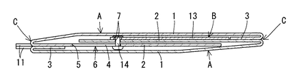
一方、店頭でこの広告表示具を使用する際には、図5及び図6に示すように、外面板1の両側の折曲部Cを内側に押し込むことにより、両外面板1から成る周壁が円錐状をなすように各外面板1を湾曲させる。
【0017】
これにより、摺合板2の重なりが深くなって、ビス14が鉤形穴6の横溝部4に沿って終端側へスライドし、ビス14が横溝部4の終端に達したとき、鉤形穴6の縦溝部5と縦長穴7とが一致する。
【0018】
この状態で、ビス14を鉤形穴6の縦溝部5と縦長穴7に沿って奥側へスライドさせると、外面板1が湾曲した立体的な形状に保持される。なお、このとき、底片8を重ね合わせて、差込片9を切込10に差し込む。
【0019】
このように、上記広告表示具を立体構造に組み立てた状態では、包装紙に包まれた花束のイメージがリアルに表現されるので、消費者の購買意欲をそそることができ、販売促進効果が期待できる。
【0020】
【発明の効果】
以上のように、この発明に係る広告表示具は、厚紙を折り曲げて簡単に製造でき、周壁をなす外面板の両側の折曲部を内側に押し込み、ビスをスライドさせてロックするだけで、外面板が湾曲した立体的な形状に保持されて、扁平な折畳状態から迅速に組み立てることができ、消費者への高い訴求効果が得られる。
【図面の簡単な説明】
【図1】この発明の実施形態に係る広告表示具の各部材のブランクを示す図
【図2】同上の製造時の一過程を示す斜視図
【図3】同上の扁平な折畳状態を示す斜視図
【図4】同上の縦断正面図
【図5】同上の立体構造への組立状態を示す斜視図
【図6】同上の縦断正面図
【符号の説明】
A 本体
B 装飾板
C 折曲部
1 外面板
2 摺合板
3 継代片
4 横溝部
5 縦溝部
6 鉤形穴
7 縦長穴
14 ビス[0001]
BACKGROUND OF THE INVENTION
The present invention relates to an advertisement display tool having a three-dimensional structure with cardboard as a main material and curved outer surface.
[0002]
[Prior art]
For example, at a retail store, in order to promote sales of a product, an advertising board with a large printed appearance of the product may be hung. As such an advertising board, a flat one such as a cardboard having a laminated structure which is not bulky at the time of transportation and does not cost much to manufacture is usually used.
[0003]
[Problems to be solved by the invention]
However, the advertising board as described above has a problem that the image of the product cannot be realistically expressed and the appealing power to consumers is weak, and there is a demand for advertising display with higher impact.
[0004]
Accordingly, the present invention is intended to provide an advertising display tool mainly made of cardboard that can be easily assembled into a three-dimensional structure from a flat folded state and is easy to manufacture.
[0005]
[Means for Solving the Problems]
In order to solve the above-mentioned problems, the present invention is arranged so as to form a peripheral wall, and is narrower than the outer surface plate inside the pair of outer surface plates that are folded at the bent portions on both sides, and is opposed to each bent portion. A pair of sliding plates extending in front of the bent portion are provided so as to overlap each other, and one sliding plate is formed with a bowl-shaped hole in which the vertical groove portion is bent from the end of the lateral groove portion extending to the connection side with the outer surface plate. An advertisement display tool is provided in which a longitudinally elongated hole is formed in the sliding plate so as to coincide with the longitudinal groove portion of the bowl-shaped hole when both outer side plates are curved, and a screw is passed through the bowl-shaped hole and the longitudinally elongated hole.
[0006]
In such an advertising display, when the bent portions on both sides of the outer plate are pushed inward, the overlap of the sliding plates becomes deeper, and the screw slides along the lateral groove portion of the bowl-shaped hole and reaches the end of the screw. Is slid along the longitudinal groove portion and the longitudinal elongated hole of the matching bowl-shaped hole, the outer plate is held in a curved three-dimensional shape.
[0007]
Further, in the above advertisement display tool, the pair of outer surface plates and the slidable plate are formed to be widened, a bowl-shaped hole and a vertically long hole are provided on the front end side of the slidable plate, and the peripheral wall composed of both outer surface plates forms a conical shape during assembly. By doing so, it is possible to realistically represent an image of a bouquet or the like wrapped in wrapping paper.
[0008]
DETAILED DESCRIPTION OF THE INVENTION
Hereinafter, as an embodiment of the present invention, an advertisement display tool that schematically represents a wrapped bouquet for use in the promotion of cut flowers will be described with reference to the accompanying drawings.
[0009]
As shown in FIG. 1, this advertisement display tool is composed of a pair of main bodies A representing wrapping paper and a decorative board B representing flowers. Each main body A has a
[0010]
Then, the
[0011]
Each main body A has a convex lens-shaped bottom piece 8 connected to the lower edge of the
[0012]
In addition, the decorative plate B includes a protruding
[0013]
In order to assemble this advertising display from the members as described above, as shown in FIG. 2, the decorative plate
[0014]
And the
[0015]
In this state, the
[0016]
On the other hand, when using this advertising display tool at a storefront, as shown in FIGS. 5 and 6, by pushing inward the bent portions C on both sides of the
[0017]
As a result, the overlapping of the
[0018]
In this state, when the
[0019]
In this way, in the state where the advertising display is assembled in a three-dimensional structure, the image of the bouquet wrapped in the wrapping paper is realistically expressed, which can inspire consumers to purchase and is expected to have a sales promotion effect. it can.
[0020]
【The invention's effect】
As described above, the advertising display device according to the present invention can be easily manufactured by bending cardboard, and the outer side plate forming the peripheral wall is pushed inward, and the screw is slid and locked. The face plate is held in a curved three-dimensional shape and can be quickly assembled from a flat folded state, and a high appealing effect to consumers can be obtained.
[Brief description of the drawings]
FIG. 1 is a view showing a blank of each member of an advertising display device according to an embodiment of the present invention. FIG. 2 is a perspective view showing a process during manufacture. FIG. 3 is a flat folded state. Perspective view [FIG. 4] Same as the above vertical front view [FIG. 5] Perspective view showing the assembly state of the same three-dimensional structure [FIG. 6] Same as the above vertical front view [Description of symbols]
A Body B Decorative plate
Claims (2)
Priority Applications (1)
| Application Number | Priority Date | Filing Date | Title |
|---|---|---|---|
| JP2002107372A JP4064706B2 (en) | 2002-04-10 | 2002-04-10 | Advertising display |
Applications Claiming Priority (1)
| Application Number | Priority Date | Filing Date | Title |
|---|---|---|---|
| JP2002107372A JP4064706B2 (en) | 2002-04-10 | 2002-04-10 | Advertising display |
Publications (2)
| Publication Number | Publication Date |
|---|---|
| JP2003302902A JP2003302902A (en) | 2003-10-24 |
| JP4064706B2 true JP4064706B2 (en) | 2008-03-19 |
Family
ID=29391402
Family Applications (1)
| Application Number | Title | Priority Date | Filing Date |
|---|---|---|---|
| JP2002107372A Expired - Fee Related JP4064706B2 (en) | 2002-04-10 | 2002-04-10 | Advertising display |
Country Status (1)
| Country | Link |
|---|---|
| JP (1) | JP4064706B2 (en) |
Families Citing this family (1)
| Publication number | Priority date | Publication date | Assignee | Title |
|---|---|---|---|---|
| CN104584103A (en) * | 2012-08-07 | 2015-04-29 | 株式会社得纳克司 | Three-dimensional pop-up display |
-
2002
- 2002-04-10 JP JP2002107372A patent/JP4064706B2/en not_active Expired - Fee Related
Also Published As
| Publication number | Publication date |
|---|---|
| JP2003302902A (en) | 2003-10-24 |
Similar Documents
| Publication | Publication Date | Title |
|---|---|---|
| USD898737S1 (en) | Portable display | |
| USD532685S1 (en) | Storage and display carton | |
| USD599410S1 (en) | Open face simulated neon sign | |
| CN105358442A (en) | Display package | |
| USD544903S1 (en) | Point of sale terminal | |
| JP4921455B2 (en) | Product packaging box | |
| USD921102S1 (en) | Point-of-sale terminal | |
| USD496269S1 (en) | Tamper evident ice cream carton | |
| USD553669S1 (en) | Point of sale terminal | |
| JP4064706B2 (en) | Advertising display | |
| USD578884S1 (en) | Display package | |
| US1513050A (en) | Picture frame | |
| CN203158346U (en) | Foldable packaging box | |
| JP3152289U (en) | Assembled 3D advertising equipment | |
| JP4244581B2 (en) | Product advertising display | |
| JP3190511U (en) | Decorative frame for capsule dispenser | |
| JP4061035B2 (en) | plastic case | |
| USD991080S1 (en) | Snowman display | |
| USD905484S1 (en) | Cosmetic bar display | |
| JP6818561B2 (en) | Stand for smart devices | |
| JP3213444U (en) | Enclosure | |
| JP3211283U (en) | Semi-solid lantern pop | |
| JP4471483B2 (en) | Advertisement display board | |
| USD514148S1 (en) | Display viewer | |
| JP2023105533A (en) | Hanging type paper-made article display implement |
Legal Events
| Date | Code | Title | Description |
|---|---|---|---|
| A621 | Written request for application examination |
Free format text: JAPANESE INTERMEDIATE CODE: A621 Effective date: 20050216 |
|
| A977 | Report on retrieval |
Free format text: JAPANESE INTERMEDIATE CODE: A971007 Effective date: 20071203 |
|
| TRDD | Decision of grant or rejection written | ||
| A01 | Written decision to grant a patent or to grant a registration (utility model) |
Free format text: JAPANESE INTERMEDIATE CODE: A01 Effective date: 20071211 |
|
| A61 | First payment of annual fees (during grant procedure) |
Free format text: JAPANESE INTERMEDIATE CODE: A61 Effective date: 20071227 |
|
| R150 | Certificate of patent or registration of utility model |
Free format text: JAPANESE INTERMEDIATE CODE: R150 |
|
| FPAY | Renewal fee payment (event date is renewal date of database) |
Free format text: PAYMENT UNTIL: 20110111 Year of fee payment: 3 |
|
| FPAY | Renewal fee payment (event date is renewal date of database) |
Free format text: PAYMENT UNTIL: 20110111 Year of fee payment: 3 |
|
| FPAY | Renewal fee payment (event date is renewal date of database) |
Free format text: PAYMENT UNTIL: 20110111 Year of fee payment: 3 |
|
| FPAY | Renewal fee payment (event date is renewal date of database) |
Free format text: PAYMENT UNTIL: 20120111 Year of fee payment: 4 |
|
| FPAY | Renewal fee payment (event date is renewal date of database) |
Free format text: PAYMENT UNTIL: 20120111 Year of fee payment: 4 |
|
| FPAY | Renewal fee payment (event date is renewal date of database) |
Free format text: PAYMENT UNTIL: 20130111 Year of fee payment: 5 |
|
| FPAY | Renewal fee payment (event date is renewal date of database) |
Free format text: PAYMENT UNTIL: 20130111 Year of fee payment: 5 |
|
| FPAY | Renewal fee payment (event date is renewal date of database) |
Free format text: PAYMENT UNTIL: 20130111 Year of fee payment: 5 |
|
| LAPS | Cancellation because of no payment of annual fees |