JP4064530B2 - Reciprocating compressor - Google Patents
Reciprocating compressor Download PDFInfo
- Publication number
- JP4064530B2 JP4064530B2 JP15361998A JP15361998A JP4064530B2 JP 4064530 B2 JP4064530 B2 JP 4064530B2 JP 15361998 A JP15361998 A JP 15361998A JP 15361998 A JP15361998 A JP 15361998A JP 4064530 B2 JP4064530 B2 JP 4064530B2
- Authority
- JP
- Japan
- Prior art keywords
- piston
- unload
- cylinder
- suction
- suction chamber
- Prior art date
- Legal status (The legal status is an assumption and is not a legal conclusion. Google has not performed a legal analysis and makes no representation as to the accuracy of the status listed.)
- Expired - Fee Related
Links
Images


Landscapes
- Compressor (AREA)
Description
【0001】
【発明の属する技術分野】
本発明は、例えば空気圧縮機として好適に用いられる往復動型圧縮機に関し、特に、負荷運転と無負荷運転の制御を行うアンロード機構を有した往復動型圧縮機に関する。
【0002】
【従来の技術】
一般に、往復動型圧縮機は、シリンダと、該シリンダ内に往復動可能に設けられたピストンと、前記シリンダ上に搭載され、内部に吸込室と吐出室とが形成されたシリンダヘッドと、該シリンダヘッドの下面側に取付けられ、該シリンダヘッドの吸込室を前記シリンダ内に対して連通,遮断する弁体を有する吸込弁と、前記シリンダヘッドに設けられ、無負荷運転時に該吸込弁を強制的に開弁するアンロード機構とを備えている。
【0003】
また、前記アンロード機構は、底部側に前記吸込室と連通する挿通孔が形成された有底筒状のアンロードシリンダと、基端側が該アンロードシリンダ内に摺動可能に挿嵌され、先端側が該アンロードシリンダの挿通孔から前記吸込室内に突出したアンロードピストンとから構成している。
【0004】
そして、圧縮機の起動と同時に負荷運転を行って、吸込行程で吸込弁を開弁し、圧縮行程で吐出弁を開弁させることは電動モータ等の駆動源に大きな負荷がかかる。このため、アンロード機構は、吸込弁を強制的に開弁し、往復動型圧縮機の無負荷運転を行うものである。
【0005】
そこで、従来技術による往復動型圧縮機として、空気圧縮機を例に挙げ、図6ないし図8に基づいて説明する。
【0006】
1は例えば鉄、アルミニウム等の金属材料によって略円筒状に形成されたシリンダを示し、該シリンダ1の上端部1Aには後述の弁座板3およびシリンダヘッド7がボルト等(図示せず)により固着されている。また、シリンダ1の上端部1Aには後述する吸込弁13の弁開度を規制する段部2が形成されている。
【0007】
3はシリンダ1の上端部1A上に設けられた弁座板で、該弁座板3は略矩形状の平板として形成され、後述するピストン11との間でシリンダ1内に圧縮室4を画成している。また、弁座板3には、圧縮室4に連通するように吸込孔5と吐出孔6とが形成されている。
【0008】
7はシリンダ1上に弁座板3を挟んで搭載されたシリンダヘッドを示し、該シリンダヘッド7は、例えば鉄、アルミニウム等の金属材料によって形成されている。また、シリンダヘッド7には弁座板3との間でシリンダヘッド7内に吸込室8と吐出室9とを画成する隔壁7Aが形成されている。また、シリンダヘッド7には吸込ポート7Bと吐出ポート(図示せず)とが形成され、吸込ポート7Bは吸込室8を経由して吸込孔5と連通し、吐出ポートは吐出室9を経由して吐出孔6と連通している。
【0009】
10はシリンダヘッド7の吸込室8に位置して後述のアンロード機構19が取付けられる取付筒部で、該取付筒部10は有底筒状に、かつ一体的に形成され、該取付筒部10の底部側には、吸込孔5の上方に位置して吸込室8と連通した挿通孔10Aが穿設されている。なお、取付筒部10は、シリンダヘッド7と別部材によって形成し、該シリンダヘッド7にねじ止め、溶接等の手段で固着する構成としてもよい。
【0010】
11はシリンダ1内に摺動可能に挿嵌されたピストンで、該ピストン11は連接棒12を用いてクランク軸(図示せず)に連結され、このクランク軸を電動モータ等の駆動源で回転させることによってシリンダ1内を往復動する。
【0011】
13は吸込孔5を開,閉すべく弁座板3の下面側(圧縮室4側)に取付けられた吸込弁を示し、該吸込弁13は基端側がボルト14等で弁座板3の下面に固着され先端側が自由端となった弁板15からなり、該弁板15はばね性を有する薄板によって形成されている。
【0012】
16は吐出孔6を開,閉すべく弁座板3の上面側(吐出室9側)に取付けられた吐出弁で、該吐出弁16は基端側がボルト17等で弁座板3に固着された長尺な弁板18からなり、該弁板18の先端側は自由端となって吐出孔6の周囲まで延びている。
【0013】
19は吸込孔5の上方に位置してシリンダヘッド7の取付筒部10に取付けられたアンロード機構を示し、該アンロード機構19は、後述のアンロードブッシュ20、アンロードピストン21および保持ばね25等から構成され、その作動時にはアンロードピストン21の押圧部21Bが吸込弁13の弁板15を押動し、該吸込弁13を強制的に開弁状態に保持することによって圧縮機を無負荷運転させる。
【0014】
20は取付筒部10の上側開口部を施蓋するアンロードブッシュで、該アンロードブッシュ20は、取付筒部10と共にアンロードシリンダを形成する筒部20Aと、該筒部20Aの上側に形成された蓋部20Bとから構成されている。また、蓋部20Bの中央部には、後述のエア室23に連通した接続ポート20Cが形成され、該接続ポート20Cには例えばエア導管(図示せず)等が接続される。
【0015】
また、このエア導管は外部のエアタンク等に電磁弁(いずれも図示せず)等を介在させて接続されている。そして、エアタンク内が規定圧力に達したとき、アンロード機構19はこの電磁弁を開弁し、エアタンク内のエア圧(圧縮空気)がエア導管を通してエア室23内に供給することにより、無負荷運転を行う。
【0016】
21は吸込弁13の弁板15を押動するアンロードピストンを示し、該アンロードピストン21は、図8に示すように、例えば、真鍮、鉄、ステンレス等の金属材料によって軸方向に伸長した棒状体として形成されている。ここで、アンロードピストン21は、取付筒部10の挿通孔10Aを挿通して吸込室8内へ突出するピストン本体21Aと、該ピストン本体21Aの先端側に位置して軸方向に延びる小径な押圧部21Bと、ピストン本体21Aの基端側に位置しアンロードブッシュ20の筒部20A内に摺動可能に挿嵌された受圧部21Cと、該受圧部21Cの外周側に形成されたOリング取付溝21Dとから構成されている。
【0017】
また、前記アンロードピストン21の外周には、自己潤滑性の樹脂材料、例えば、カーボンを混練したフェノール樹脂、四弗化樹脂等からなる潤滑膜22が被覆されている。
【0018】
ここで、前記アンロードピストン21の受圧部21Cは、筒部20A内で蓋部20Bとの間にエア室23を画成している。また、受圧部21Cの外周側に形成されたOリング取付溝21D内にはOリング24が装着されている。さらに、該Oリング24にはモリブデン系の耐熱グリースが添着され、このグリースにより、受圧部21Cと筒部20Aとの間をシールしている。
【0019】
25はアンロード機構19の停止時にアンロードピストン21を停止側位置に保持するための保持ばねで、該保持ばね25はピストン本体21Aの周囲に配設され、上端側が受圧部21Cの下面に当接し、下端側が取付筒部10内の底部側に当接している。
【0020】
このように構成される従来技術の空気圧縮機では、電動モータ等の駆動源(図示せず)によってクランク軸が回転駆動されると、ピストン11がシリンダ1内で往復動し、圧縮室4を拡縮させる。
【0021】
そして、圧縮機の負荷運転時には、ピストン11がシリンダ1内で下向きに摺動する吸込行程で圧縮室4が吸込室8および吐出室9よりも低圧となるから、吸込弁13が開弁し吐出弁16が閉弁することにより、外部の空気が吸込ポート7Bから吸込室8を経由して圧縮室4内に吸込まれる。
【0022】
また、ピストン11がシリンダ1内で上向きに摺動する吐出行程では、圧縮室4が吸込室8および吐出室9よりも高圧となるから、吸込弁13が閉弁し吐出弁16が開弁することにより、圧縮室4内で圧縮された空気が吐出室9を経由して吐出ポートから圧縮空気として吐出され、外部のエアタンク等に貯留される。
【0023】
この場合、アンロード機構19は、圧縮機を負荷運転させるために電磁弁は閉弁しているから、アンロードピストン21が保持ばね25によりエア室23側へと上向きに押動され、ピストン本体21Aの押圧部21Bは吸込弁13の弁板15から離間した状態に保持される。これにより、吸込弁13の弁板15はピストン11が吸込行程と吐出行程とを繰返すのに応じて弁座板3に対して離,着座を行う。
【0024】
これに対し、圧縮機を無負荷運転させるときには、電磁弁等を開弁させることにより、アンロード機構19のエア室23内に前記エアタンク等からエア圧が供給される。これにより、アンロードピストン21は、図7のように、保持ばね25に抗して下向きに摺動し、先端の押圧部21Bが吸込弁13の弁板15を下向きに押動し、該吸込弁13を強制的に開弁状態に保持する。
【0025】
【発明が解決しようとする課題】
ところで、上述した従来技術による往復動型圧縮機では、アンロード機構19のアンロードピストン21全体が金属材料によって形成されているため、次のような問題があった。
【0026】
第1に、アンロードピストン21全体が金属材料により形成されていると、その質量が大きくなるため、アンロード機構19が無負荷運転を開始するときには、アンロードピストン21の押圧部21Bが吸込弁13の弁板15に勢いよく衝突する。この結果、両者が衝突するときの衝撃力が大きくなり、アンロードピストン21の押圧部21B、弁板15等を破損してしまう虞れがあった。
【0027】
第2に、無負荷運転の開始時には、アンロードピストン21の押圧部21Bが大きな慣性力をもって吸込弁13の弁板15に衝突すると、両者の衝突音が発生し易くなり、特に重量の金属材料からなるアンロードピストン21が金属製の弁板15に勢いよく衝突したときには、騒音レベルが大きくなり易い。
【0028】
第3に、アンロードピストン21は金属材料によって形成されているため、予め熱膨張を考えた太さに形成され、ピストン本体21Aと挿通孔10Aとの間のクリアランスも大きく設定されている。このため、アンロードピストン21の取付ガタが大きくなり、この取付ガタによって、ピストン本体21Aと挿通孔10Aは早期摩耗していまい、アンロード機構19の寿命が短くなってしまう。
【0029】
本発明は上述した従来技術の問題に鑑みなされたもので、アンロードピストンが吸込弁に衝突するときの衝撃を緩和し、これらの耐久性を高めると共に、アンロードピストンが摺動する部分の偏摩耗を低減できるようにした往復動型圧縮機を提供することを目的としている。
【0030】
【課題を解決するための手段】
上述した課題を解決するために、本発明が採用する往復動型圧縮機は、シリンダと、該シリンダ内に往復動可能に設けられたピストンと、前記シリンダ上に搭載され、内部に吸込室と吐出室とが形成されたシリンダヘッドと、該シリンダヘッドの下面側に取付けられ、該シリンダヘッドの吸込室を前記シリンダ内に対して連通,遮断する弁体を有する吸込弁と、前記シリンダヘッドに設けられ、無負荷運転時に該吸込弁を強制的に開弁するアンロード機構とを備え、該アンロード機構を、底部側に前記吸込室と連通する挿通孔が形成された有底筒状のアンロードシリンダと、基端側が該アンロードシリンダ内に摺動可能に挿嵌され、先端側が該アンロードシリンダの挿通孔から前記吸込室内に突出したアンロードピストンとから構成している。
【0031】
そして、請求項1に記載の発明が採用する構成の特徴は、前記アンロードピストンは、軸方向に伸長した棒状体からなり、前記挿通孔内を挿通して吸込室内に突出したピストン本体と、該ピストン本体の先端側に位置して無負荷運転時に前記吸込弁を押圧する押圧部と、前記ピストン本体の基端側に位置して前記アンロードシリンダ内に摺動可能に挿嵌された受圧部とから構成し、前記アンロードピストンは、前記ピストン本体を樹脂材料によって形成し、前記受圧部を金属により形成したことにある。
【0032】
このように構成することにより、アンロードピストンのピストン本体を樹脂材料によって形成し、受圧部を金属により形成することができる。これにより、アンロードピストン全体を軽量化でき、無負荷運転を開始したときには、アンロードシリンダ内を摺動するアンロードピストンの慣性力を低減できる。これにより、アンロードピストンの押圧部で吸込弁の弁体を下側に押動するときでも、この押圧部が吸込弁と衝突するときの衝撃力を緩和することができ、両者が当接するときの衝突音も低減できる。
【0033】
さらに、ピストン本体を樹脂材料により形成したから、該ピストン本体とアンロードシリンダの挿通孔との間のクリアンランスは、熱膨張を考慮した大きさに予め設定する必要はなく、摺動時においてもピストン本体のみが摩耗することにより、シリンダヘッドの挿通孔の摩耗を低減できる。
【0034】
一方、請求項2の発明が採用する構成の特徴は、前記アンロードピストンは、軸方向に伸長した棒状体からなり、前記挿通孔内を挿通して吸込室内に突出したピストン本体と、該ピストン本体の先端側に位置して無負荷運転時に前記吸込弁を押圧する押圧部と、前記ピストン本体の基端側に位置して前記アンロードシリンダ内に摺動可能に挿嵌された受圧部とから構成し、前記アンロードピストンは、前記ピストン本体を樹脂材料によって形成し、前記押圧部を金属により形成したことにある。
【0035】
このように構成することにより、アンロードピストンのピストン本体を樹脂材料によって形成し、押圧部を金属により形成することができる。
【0036】
また、請求項3の発明のように、前記アンロードピストンのピストン本体を自己潤滑性の樹脂材料によって形成することにより、アンロードピストンのピストン本体と挿通孔との間の摺動性を高めることができ、偏摩耗を低減できる。
【0037】
また、請求項4の発明では、前記アンロードピストンのピストン本体を繊維強化樹脂材料によって形成している。
【0038】
これにより、例えばガラス繊維で強化した樹脂材料等を用いてアンロードピストンを軽量で高強度に形成することができる。
【0039】
また、請求項5の発明のように、アンロードピストンにフェノール樹脂を用いることができる。
【0040】
【発明の実施の形態】
以下、本発明の実施の形態を、図1ないし図5の添付図面に基づいて、詳細に説明する。
【0041】
ここで、本発明の実施の形態の説明に先立ち、図1および図2により本発明の前提となる第1の参考例について説明する。なお、第1の参考例では従来技術と同一の構成要素に同一の符号を付し、その説明を省略するものとする。
【0042】
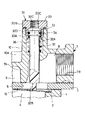
31は第1の参考例によるアンロード機構を示し、該アンロード機構31は、吸込孔5の上方に位置してシリンダヘッド7の取付筒部10に取付けられ、該アンロード機構31は、アンロードブッシュ20、後述するアンロードピストン32および保持ばね35等から構成され、その作動時にはアンロードピストン32の押圧部32Bが吸込弁13の弁板15を下側に押動し、該吸込弁13を強制的に開弁状態に保持することによって圧縮機を無負荷運転させる。
【0043】
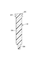
32は第1の参考例に適用されるアンロードピストンを示し、該アンロードピストン32は、図2に示すように、その全体が自己潤滑性の樹脂材料、例えば、カーボンを混練した熱硬化性のフェノール樹脂、四弗化樹脂等によって形成されている。
【0044】
ここで、前記アンロードピストン32は、取付筒部10の挿通孔10Aを挿通して吸込室8内へ突出するピストン本体32Aと、該ピストン本体32Aの先端側に位置して軸方向に延びる小径な押圧部32Bと、前記ピストン本体32Aの基端側に位置しアンロードブッシュ20の筒部20A内に摺動可能に挿嵌された受圧部32Cと、該受圧部32Cの外周側に形成されたOリング取付溝32Dとから構成されている。
【0045】
また、前記アンロードピストン32の受圧部32Cは、筒部20A内で蓋部20Bとの間にエア室33を画成している。また、受圧部32Cの外周側に形成されたOリング取付溝32D内にはOリング34が装着されている。さらに、該Oリング34にはモリブデン系の耐熱グリースが添着され、このグリースにより、受圧部32Cと筒部20Aとの間をシールしている。
【0046】
35はアンロード機構31の停止時にアンロードピストン32を停止側位置に保持するための保持ばねで、該保持ばね35はピストン本体32Aの周囲に配設され、上端側が受圧部32Cに当接し、下端側が取付筒部10の底部側に当接している。そして、保持ばね35はこの状態でアンロードピストン32をエア室33側に向けて常時付勢している。
【0047】
第1の参考例による空気圧縮機は上述の如き構成をするもので、その基本的動作については従来技術によるものと格別差異はない。
【0048】
然るに、第1の参考例によれば、アンロードピストン32を自己潤滑性の樹脂材料によって形成したから、該アンロードピストン32の重量を例えば従来技術のアンロードピストン21の1/3程度に軽量化でき、アンロードピストン32が変位するときに生じる慣性力を確実に低減させることができる。
【0049】
これにより、アンロード機構31が無負荷運転を開始するときには、アンロードピストン32の押圧部32Bが、下側に位置した吸込弁13の弁板15に勢いよく衝突したとしても、樹脂材料によって形成された重量の軽いアンロードピストン32が衝突することになり、衝突時の衝撃力を低減し、弁板15の破損を防止することができる。
【0050】
また、アンロードピストン32の押圧部32Bも樹脂材料により形成しているから、無負荷運転を開始してアンロードピストン32の押圧部32Bが吸込弁13の弁板15に衝突するとき、発生する衝突音を低減できる。
【0051】
さらに、アンロードピストン32は、自己潤滑性の樹脂材料によって形成されているから、ピストン本体32Aと挿通孔10Aとのクリアランス、ピストン本体32Aと筒部20Aとの間のクリアランスを、予め狭く設定して取付ガタを小さくしたとしても、アンロードピストン32の材料は自己潤滑性を備えているから、該アンロードピストン32はアンロードシリンダに対して円滑に摺動させ、摺動部分の偏摩耗を低減できる。
【0052】
しかも、アンロードピストン32が熱膨張してピストン本体32Aと挿通孔10Aとの間のクリアランスが狭くなり、ピストン本体32Aが挿通孔10Aに接触したとしても、アンロードピストン32の摺動時には、樹脂材料で形成されたピストン本体32Aが摩耗するだけですむ。これにより、アンロードピストン32は、挿通孔10Aが摩耗するのを防止することができる。
【0053】
一方、アンロードピストン32の受圧部32Cとアンロードブッシュ20の筒部20Aとの間のクリアランスに関し、アンロードピストン32が熱膨張し、このクリアランスが狭くなったとしても、樹脂で形成された受圧部32Cが摩耗するだけですむ。これにより、アンロードピストン32は、アンロードブッシュ20の筒部20Aが摩耗するのを防止することができる。
【0054】
さらに、前述したように、アンロードピストン32が挿通孔10A、筒部20Aに対して片寄った偏摩耗を起こしたとしても、アンロードピストン32は低廉安価な樹脂材料で製造することが可能であるから、交換して使用することもでき、アンロード機構31の寿命を延ばし、空気圧縮機の信頼性を高めることができる。
【0055】
また、アンロードピストン32を樹脂材料によって形成することにより、その表面に防錆処理等を施す必要がなくなり、従来技術の潤滑膜22等も省略できると共に、アンロードピストン32を形成するときの工数、コスト等を低減させることができる。
【0056】
かくして、アンロードピストン32は、全体を自己潤滑性の樹脂材料によって形成したから、アンロード機構31の作動時にアンロードピストン32の押圧部32Bが吸込弁13の弁板15に強く衝突するときの衝撃力を低減でき、吸込弁13が破損するのを確実に抑えると共に、押圧部32Bが弁板15に衝突するときの衝突音を低減することができる。これにより、これらアンロードピストン32と吸込弁13の耐久性と寿命を大幅に向上し、空気圧縮機の圧縮性能等を長期間に亘って良好に保持することができる。
【0057】
次に、図3は本発明の前提となる第2の参考例を示し、第2の参考例による往復動型圧縮機の特徴は、アンロードピストン41のピストン本体41A、押圧部41Bおよび受圧部41Cを繊維強化樹脂材料によって形成したことにある。
【0058】
ここで、この繊維強化樹脂材料は、例えばカーボンを混練したフェノール樹脂、四弗化樹脂等の自己潤滑性を有する樹脂材料に対して、ガラス繊維等の短繊維を混入することにより形成した高強度の樹脂材料(FRP)等によって構成されている。
【0059】
かくして、このように構成される第2の参考例でも、前記第1の実施の形態とほぼ同様の作用効果を得ることができ、アンロードピストン41の重量を従来技術の1/3程度に軽量化できると共に、その押圧部41Bが弁板15に衝突するときの衝撃力、衝突音を確実に低減させることができる。
【0060】
そして、特に第2の参考例では、繊維強化樹脂材料を用いることにより、軽量なアンロードピストン41に対して高い強度と耐摩耗性とを与えることができ、例えばアンロードピストン41と取付筒部10等との摺動面に潤滑油等を塗布することなく、これらの耐久性、寿命を向上させることができる。
【0061】
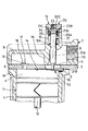
さて、図4は本発明による往復動型圧縮機の第1の実施の形態を示している。
【0062】
第1の実施の形態の特徴は、前述した第1,第2の参考例とは異なり、アンロードピストン51を、ピストン本体52Aと押圧部52Bを自己潤滑性の樹脂材料で形成したピストン部材52と、受圧部53AとOリング取付溝53Bを金属材料で形成した受圧部材53とから構成したことにある。ここで、ピストン部材52と受圧部材53とは、例えばインサート成形、圧入、ねじ止め等の手段によって一体化されている。
【0063】
かくして、このように構成される第1の実施の形態でも、前記第1の参考例とほぼ同様の作用効果を得ることができる。そして、特に第1の実施の形態では、受圧部53Aの強度をより高めることができ、圧縮機が無負荷運転から通常の負荷運転に切換わる毎に、アンロードピストン51の受圧部53Aが保持ばね35の付勢力によりアンロードブッシュ20の蓋部20Bに衝突を繰返して破損するのを確実に防止することができる。
【0064】
また、例えばピストン部材52と受圧部材53とをねじ止め等によって着脱可能に一体化することにより、アンロードピストン51を交換する場合には、ピストン部材52のみを交換すればよくなり、受圧部材53等の材料を節約することができる。なお、アンロードピストン51の先端側は、図4中の点線で示すように、押圧部52B′を截頭円錐状に形成してもよい。
【0065】
次に、図5は本発明による往復動型圧縮機の第2の実施の形態を示している。
【0066】
第2の実施の形態の特徴は、アンロードピストン61を、ピストン本体62Aと受圧部62Bを自己潤滑性の樹脂材料で形成したピストン部材62と、例えばインサート成形等の手段を用いて該ピストン部材62の先端側に一体化された金属製の押圧部63とから構成したことにある。
【0067】
かくして、このように構成される第2の実施の形態でも、前記第1の参考例とほぼ同様の作用効果を得ることができる。そして、特に第2の実施の形態では、押圧部63のみを金属材料で形成することにより、アンロードピストン61の軽量化を図りつつ押圧部63の強度をより向上でき、押圧部63が弁板15と衝突したときに破損するのを確実に防止することができる。
【0068】
なお、前記第1および第2の実施の形態では、アンロードピストン51,61のピストン本体52A,62A等を自己潤滑性を有する樹脂材料によって構成したが、本発明はこれに限らず、ピストン本体52A,62A等を第2の参考例のアンロードピストン41と同様にFRP等の繊維強化樹脂材料によって形成する構成としてもよい。
【0069】
また、前記第1,2の実施の形態では、往復動型圧縮機として空気圧縮機を例に挙げて説明したが、本発明はこれに限らず、例えば空気以外の気体を圧縮する圧縮機等にも広く適用できる。
【0070】
【発明の効果】
以上詳述した通り、請求項1に記載の発明によれば、ピストン本体、押圧部および受圧部からなるアンロードピストンのうち、前記ピストン本体を樹脂材料によって形成し、前記受圧部を金属により形成したから、アンロードピストン全体の軽量化を図ることができ、その摺動時に生じる慣性力を確実に低減させることができる。これにより、無負荷運転を開始したときには、アンロードピストンの押圧部が吸込弁の弁体に強く衝突するときでも、このときの衝撃力を緩和することができ、衝突するときの衝突音も小さく抑えることができる。
【0071】
特に、アンロードピストンのピストン本体を樹脂材料によって形成し、受圧部を金属で形成したから、受圧部の強度をより高めることができ、往復動圧縮機が無負荷運転から通常の負荷運転に切換わる毎に、アンロードピストンの受圧部がアンロードシリンダ側に衝突を繰返して破損するのを確実に防止することができる。さらに、ピストン本体を樹脂材料により形成したから、該ピストン本体とアンロードシリンダの挿通孔との間のクリアンランスは、熱膨張を考慮した大きさに予め設定する必要はなく、摺動時においてもピストン本体のみを摩耗させることにより、シリンダヘッドの挿通孔の摩耗を防止することができる。これにより、吸込弁が破損するのを確実に防止でき、往復動型圧縮機の耐久性と寿命を高めることができる。
【0072】
一方、請求項2に記載の発明によれば、アンロードピストンのピストン本体を樹脂材料によって形成し、押圧部を金属で形成したから、アンロードピストンの軽量化を図りつつ押圧部の強度をより向上でき、押圧部が弁板と衝突したときに破損するのを確実に防止することができる。
【0073】
また、請求項3に記載の発明によれば、アンロードピストンのうち少なくともピストン本体を自己潤滑性の樹脂材料によって形成したから、アンロードピストンがアンロードシリンダ内で摺動するときの潤滑性を高めることができ、アンロードピストンを円滑に動作させることができると共に、これらの摺動部の偏摩耗を低減できる。
【0074】
また、請求項4に記載の発明によれば、アンロードピストンのうち少なくともピストン本体を繊維強化樹脂材料によって形成したから、アンロードピストン全体の軽量化を図りつつ、アンロードピストンに対して高い強度と耐摩耗性とを与えることができ、その耐久性、寿命を向上させることができる。
【0075】
また、請求項5に記載の発明によれば、アンロードピストンに用いる樹脂材料をフェノール樹脂により構成したから、アンロードピストンの重量を従来技術に対して軽量化でき、その押圧部が弁板に衝突するときの衝撃力、衝突音を確実に低減させることができる。
【図面の簡単な説明】
【図1】 本発明の前提となる第1の参考例による空気圧縮機のアンロード機構等を示す縦断面図である。
【図2】 図1に示すアンロードピストンの縦断面図である。
【図3】 第2の参考例による空気圧縮機のアンロードピストンを示す縦断面図である。
【図4】 本発明の第1の実施の形態による空気圧縮機のアンロードピストンを示す縦断面図である。
【図5】 第2の実施の形態による空気圧縮機のアンロードピストンを示す縦断面図である。
【図6】 従来技術による空気圧縮機を示す縦断面図である。
【図7】 従来技術による空気圧縮機のアンロード機構等を示す縦断面図である。
【図8】 図7に示すアンロードピストンの縦断面図である。
【符号の説明】
1 シリンダ
7 シリンダヘッド
8 吸込室
10 取付筒部
10A 挿通孔
11 ピストン
13 吸込弁
15 弁板
20 アンロードブッシュ
31 アンロード機構
32,41,51,61 アンロードピストン
32A,41A,52A,62A ピストン本体
32B,41B,52B,52B′,63 押圧部
32C,41C,53A,62B 受圧部
32D,53B Oリング取付溝
52,62 ピストン部材
53 受圧部材[0001]
BACKGROUND OF THE INVENTION
The present invention relates to a reciprocating compressor suitably used as, for example, an air compressor, and more particularly to a reciprocating compressor having an unload mechanism that controls load operation and no-load operation.
[0002]
[Prior art]
Generally, a reciprocating compressor includes a cylinder, a piston provided in the cylinder so as to be capable of reciprocating, a cylinder head mounted on the cylinder and having a suction chamber and a discharge chamber formed therein, A suction valve that is attached to the lower surface of the cylinder head and has a valve body that communicates and shuts off the suction chamber of the cylinder head with respect to the inside of the cylinder, and is provided in the cylinder head and forces the suction valve during no-load operation. And an unloading mechanism for automatically opening the valve.
[0003]
Further, the unload mechanism has a bottomed cylindrical unload cylinder in which an insertion hole communicating with the suction chamber is formed on the bottom side, and a base end side is slidably inserted into the unload cylinder. The front end side is comprised from the unload piston which protruded in the said suction chamber from the penetration hole of this unload cylinder.
[0004]
And at the same time when the compressor starts,lineOpen the suction valve and compresslineOpening the discharge valve as much as this places a heavy load on a drive source such as an electric motor. For this reason, the unload mechanism forcibly opens the suction valve to perform no-load operation of the reciprocating compressor.
[0005]
Therefore, an air compressor will be described as an example of a reciprocating compressor according to the prior art and will be described with reference to FIGS.
[0006]
[0007]
[0008]
Reference numeral 7 denotes a cylinder head mounted on the
[0009]
[0010]
A
[0011]
[0012]
A
[0013]
[0014]
[0015]
The air conduit is connected to an external air tank or the like with a solenoid valve (both not shown) interposed therebetween. When the inside of the air tank reaches a specified pressure, the
[0016]
[0017]
The outer periphery of the unload
[0018]
Here, the
[0019]
[0020]
In the conventional air compressor configured as described above, when the crankshaft is rotationally driven by a drive source (not shown) such as an electric motor, the
[0021]
During the load operation of the compressor, the
[0022]
Further, in the discharge stroke in which the
[0023]
In this case, since the electromagnetic valve is closed in the unload
[0024]
On the other hand, when the compressor is operated with no load, air pressure is supplied from the air tank or the like into the
[0025]
[Problems to be solved by the invention]
By the way, in the above-described reciprocating compressor according to the prior art, the entire unload
[0026]
First, when the entire unload
[0027]
Secondly, at the start of no-load operation, if the
[0028]
Third, since the unload
[0029]
The present invention has been made in view of the above-described problems of the prior art. It alleviates the impact when the unload piston collides with the suction valve, enhances the durability of the unload piston, and offsets the portion where the unload piston slides. It is an object of the present invention to provide a reciprocating compressor capable of reducing wear.
[0030]
[Means for Solving the Problems]
In order to solve the above-described problems, a reciprocating compressor employed by the present invention includes a cylinder, a piston provided in the cylinder so as to be capable of reciprocating, a suction chamber mounted on the cylinder, A cylinder head formed with a discharge chamber, a suction valve attached to the lower surface side of the cylinder head and having a valve body for communicating and blocking the suction chamber of the cylinder head with respect to the inside of the cylinder; and the cylinder head Provided with an unloading mechanism that forcibly opens the suction valve during no-load operation, and the unloading mechanism has a bottomed cylindrical shape in which an insertion hole communicating with the suction chamber is formed on the bottom side. An unload cylinder and a base end side are slidably inserted into the unload cylinder, and a distal end side is constituted by an unload piston projecting from the insertion hole of the unload cylinder into the suction chamber.
[0031]
The feature of the configuration adopted by the invention of
[0032]
By configuring in this way,The piston body of the unload piston can be formed from a resin material, and the pressure receiving portion can be formed from metal. ThisThe entire unload piston can be reduced in weight, and when the no-load operation is started, the inertial force of the unload piston sliding in the unload cylinder can be reduced. As a result, even when the valve body of the suction valve is pushed downward by the pressing portion of the unload piston, the impact force when the pressing portion collides with the suction valve can be relaxed, and both are in contact with each other The collision noise can be reduced.
[0033]
Furthermore, since the piston body is made of a resin material, the clearance between the piston body and the insertion hole of the unload cylinder does not need to be set in advance in consideration of thermal expansion. Wear of only the piston body can reduce wear of the insertion hole of the cylinder head.
[0034]
on the other handThe invention of claim 2The unloading piston is composed of a rod-like body extending in the axial direction, and is located on the front end side of the piston body that is inserted through the insertion hole and protrudes into the suction chamber. A pressure portion that presses the suction valve during no-load operation, and a pressure receiving portion that is slidably fitted in the unload cylinder and is located on the base end side of the piston body.The unload pistonSaidPiston bodyTreeFormed by fat materialAnd the pressing part is made of metal.The
[0035]
With this configuration, the piston body of the unload piston can be formed of a resin material, and the pressing portion can be formed of metal.The
[0036]
According to a third aspect of the present invention, the slidability between the piston body of the unload piston and the insertion hole is enhanced by forming the piston body of the unload piston from a self-lubricating resin material. Can reduce uneven wearit can.
[0037]
The invention of claim 4ThenThe unloading pistonofPiston bodyFiber reinforcedFormed by resin materialHaveThe
[0038]
Thus, for example, using a resin material reinforced with glass fiberUnload pistonLight weight and high strengthCan be formed.
[0039]
Claims5As in the invention, a phenol resin can be used for the unload piston.
[0040]
DETAILED DESCRIPTION OF THE INVENTION
DESCRIPTION OF THE PREFERRED EMBODIMENTS Hereinafter, embodiments of the present invention will be described in detail with reference to the accompanying drawings of FIGS.
[0041]
here,Prior to the description of the embodiment of the present invention,FIG.andFIG.ByThe present inventionAs a premiseFirstExplain a reference exampleThe In addition,First reference exampleThen, the same code | symbol is attached | subjected to the component same as a prior art, and the description shall be abbreviate | omitted.
[0042]
31 isFirst reference exampleThe unload
[0043]
32 isFirst reference exampleAs shown in FIG. 2, the unload
[0044]
Here, the unload
[0045]
Further, the
[0046]
[0047]
First reference exampleThe air compressor according to the above is configured as described above, and the basic operation is not different from that according to the prior art.
[0048]
However,First reference exampleSince the unload
[0049]
Thereby, when the unload
[0050]
Further, since the
[0051]
Further, since the unload
[0052]
Moreover, even if the unload
[0053]
On the other hand, regarding the clearance between the
[0054]
Furthermore, as described above, even if the unload
[0055]
Further, since the unload
[0056]
Thus, since the entire unload
[0057]
Next, FIG. 3 shows the present invention.Second reference example that is a prerequisite forIndicateSecond reference exampleThe feature of the reciprocating compressor is that the piston
[0058]
Here, this fiber reinforced resin material is formed by mixing short fibers such as glass fibers with a resin material having self-lubricating properties such as phenol resin and tetrafluoride resin kneaded with carbon. The resin material (FRP) or the like.
[0059]
Thus configured like thisSecond reference exampleHowever, substantially the same operational effects as those of the first embodiment can be obtained, and the weight of the
[0060]
And especiallySecond reference exampleThen, by using a fiber reinforced resin material, it is possible to give high strength and wear resistance to the lightweight unload
[0061]
NowFIG. 4 is according to the invention.Reciprocating compressorFirst1Shows an embodiment ofing.
[0062]
FirstImplementation formStatefeature is,Unlike the first and second reference examples described above,The
[0063]
Thus configured like thisFirstAlso in the embodiment, the firstReference exampleIt is possible to obtain substantially the same operational effects. And especiallyFirstIn the embodiment, the strength of the
[0064]
Further, for example, when the
[0065]
Next, FIG. 5 is according to the present invention.Reciprocating compressorFirst2Shows an embodiment ofing.
[0066]
SecondImplementation formStateThe feature is that the
[0067]
Thus configured like thisSecondAlso in the embodiment, the firstReference exampleIt is possible to obtain substantially the same operational effects. And especiallySecondIn the embodiment, by forming only the
[0068]
The first1And second2In the embodiment, the piston
[0069]
Also, the above1st and 2ndIn the embodiment, the air compressor is described as an example of the reciprocating compressor. However, the present invention is not limited to this, and can be widely applied to, for example, a compressor that compresses a gas other than air.
[0070]
【The invention's effect】
As described above in detail, according to the first aspect of the present invention, among the unload pistons including the piston main body, the pressing portion, and the pressure receiving portion.,in frontThe piston body is made of resin.ByFormingThe pressure receiving part is made of metal.Therefore, the weight of the entire unloading piston can be reduced, and the inertial force generated during the sliding can be surely reduced. As a result, when the no-load operation is started, even when the pressing portion of the unload piston strongly collides with the valve body of the suction valve, the impact force at this time can be reduced, and the collision sound at the time of collision is also small. Can be suppressed.
[0071]
In particular, since the piston body of the unload piston is made of a resin material and the pressure receiving part is made of metal, the pressure receiving part can be further strengthened, and the reciprocating compressor can be switched from no-load operation to normal load operation. It is possible to reliably prevent the pressure receiving portion of the unloading piston from repeatedly colliding with the unloading cylinder and damaging each time it is replaced.Furthermore, since the piston body is made of a resin material, the clearance between the piston body and the insertion hole of the unload cylinder does not need to be set in advance in consideration of thermal expansion. By wearing only the piston body, it is possible to prevent wear of the insertion hole of the cylinder head. Thereby, it can prevent reliably that a suction valve is damaged, and can improve durability and lifetime of a reciprocating compressor.
[0072]
on the other handAccording to the invention of
[0073]
AlsoAccording to the invention of
[0074]
According to the invention of
[0075]
MaClaim5Since the resin material used for the unload piston is made of phenolic resin, the weight of the unload piston can be reduced compared to the prior art, and the impact when the pressing portion collides with the valve plate. Force and impact noise can be reduced reliably.
[Brief description of the drawings]
FIG. 1 of the present inventionPremiseFirstReference exampleIt is a longitudinal cross-sectional view which shows the unloading mechanism etc. of the air compressor by.
FIG. 2 is a longitudinal sectional view of the unload piston shown in FIG.
FIG. 3 SecondReference exampleIt is a longitudinal cross-sectional view which shows the unload piston of the air compressor by.
[Fig. 4]Of the present inventionFirst1It is a longitudinal cross-sectional view which shows the unload piston of the air compressor by embodiment of this.
FIG. 52It is a longitudinal cross-sectional view which shows the unload piston of the air compressor by embodiment of this.
FIG. 6 is a longitudinal sectional view showing an air compressor according to the prior art.
FIG. 7 is a longitudinal sectional view showing an unload mechanism of an air compressor according to the prior art.
FIG. 8 is a longitudinal sectional view of the unload piston shown in FIG.
[Explanation of symbols]
1 cylinder
7 Cylinder head
8 Suction chamber
10 Mounting tube
10A insertion hole
11 Piston
13 Suction valve
15 Valve plate
20 Unload bush
31 Unload mechanism
32, 41, 51, 61 Unload piston
32A, 41A, 52A, 62A Piston body
32B, 41B, 52B, 52B ', 63 Pressing part
32C, 41C, 53A, 62B Pressure receiving part
32D, 53B O-ring mounting groove
52, 62 Piston member
53 Pressure receiving member
Claims (5)
前記アンロードピストンは、軸方向に伸長した棒状体からなり、前記挿通孔内を挿通して吸込室内に突出したピストン本体と、該ピストン本体の先端側に位置して無負荷運転時に前記吸込弁を押圧する押圧部と、前記ピストン本体の基端側に位置して前記アンロードシリンダ内に摺動可能に挿嵌された受圧部とから構成し、
前記アンロードピストンは、前記ピストン本体を樹脂材料によって形成し、前記受圧部を金属により形成したことを特徴とする往復動型圧縮機。A cylinder, a piston provided in the cylinder so as to be capable of reciprocating, a cylinder head mounted on the cylinder and having a suction chamber and a discharge chamber formed therein, and attached to the lower surface side of the cylinder head; A suction valve having a valve body that communicates and shuts off the suction chamber of the cylinder head with respect to the inside of the cylinder; and an unload mechanism that is provided in the cylinder head and forcibly opens the suction valve during no-load operation; The unload mechanism has a bottomed cylindrical unload cylinder in which an insertion hole communicating with the suction chamber is formed on the bottom side, and a base end side is slidably inserted into the unload cylinder. In the reciprocating compressor in which the tip side is constituted by an unload piston protruding from the insertion hole of the unload cylinder into the suction chamber,
The unload piston is composed of a rod-like body extending in the axial direction, and is inserted into the insertion hole and protrudes into the suction chamber. The unloading piston is located on the distal end side of the piston body and is in the no-load operation. And a pressure receiving portion that is located on the base end side of the piston body and is slidably inserted into the unload cylinder ,
The unloading piston, wherein the piston body is formed of a resin material, a reciprocating compressor the pressure receiving portion, characterized in that formed by metal.
前記アンロードピストンは、軸方向に伸長した棒状体からなり、前記挿通孔内を挿通して吸込室内に突出したピストン本体と、該ピストン本体の先端側に位置して無負荷運転時に前記吸込弁を押圧する押圧部と、前記ピストン本体の基端側に位置して前記アンロードシリンダ内に摺動可能に挿嵌された受圧部とから構成し、The unload piston is composed of a rod-like body extending in the axial direction, and is inserted into the insertion hole and protrudes into the suction chamber. The unloading piston is located on the distal end side of the piston body and is in the no-load operation. And a pressure receiving portion that is located on the base end side of the piston body and is slidably inserted into the unload cylinder,
前記アンロードピストンは、前記ピストン本体を樹脂材料によって形成し、前記押圧部を金属により形成したことを特徴とする往復動型圧縮機。The unload piston is a reciprocating compressor characterized in that the piston main body is formed of a resin material and the pressing portion is formed of metal.
Priority Applications (1)
| Application Number | Priority Date | Filing Date | Title |
|---|---|---|---|
| JP15361998A JP4064530B2 (en) | 1997-09-24 | 1998-05-18 | Reciprocating compressor |
Applications Claiming Priority (3)
| Application Number | Priority Date | Filing Date | Title |
|---|---|---|---|
| JP9-276571 | 1997-09-24 | ||
| JP27657197 | 1997-09-24 | ||
| JP15361998A JP4064530B2 (en) | 1997-09-24 | 1998-05-18 | Reciprocating compressor |
Related Child Applications (1)
| Application Number | Title | Priority Date | Filing Date |
|---|---|---|---|
| JP2007303049A Division JP5242137B2 (en) | 1997-09-24 | 2007-11-22 | Reciprocating compressor |
Publications (2)
| Publication Number | Publication Date |
|---|---|
| JPH11159452A JPH11159452A (en) | 1999-06-15 |
| JP4064530B2 true JP4064530B2 (en) | 2008-03-19 |
Family
ID=26482185
Family Applications (1)
| Application Number | Title | Priority Date | Filing Date |
|---|---|---|---|
| JP15361998A Expired - Fee Related JP4064530B2 (en) | 1997-09-24 | 1998-05-18 | Reciprocating compressor |
Country Status (1)
| Country | Link |
|---|---|
| JP (1) | JP4064530B2 (en) |
Families Citing this family (1)
| Publication number | Priority date | Publication date | Assignee | Title |
|---|---|---|---|---|
| KR100367610B1 (en) * | 2000-11-30 | 2003-01-14 | 엘지전자 주식회사 | Apparatus for preventing collision in compressor |
-
1998
- 1998-05-18 JP JP15361998A patent/JP4064530B2/en not_active Expired - Fee Related
Also Published As
| Publication number | Publication date |
|---|---|
| JPH11159452A (en) | 1999-06-15 |
Similar Documents
| Publication | Publication Date | Title |
|---|---|---|
| KR100422363B1 (en) | Valve assembly for compressor | |
| JP4064530B2 (en) | Reciprocating compressor | |
| JP5242137B2 (en) | Reciprocating compressor | |
| KR100246404B1 (en) | Piston Oil Supply Structure of Hermetic Electric Compressor | |
| US6513417B1 (en) | Single-headed swash-plate-type compressor with hollowed and ribbed piston | |
| CA2181850C (en) | Cylinder assembly for a reciprocating compressor | |
| CA2488982C (en) | Compressor assembly with reciprocating piston and vented cylinder | |
| US20100034679A1 (en) | Refrigerant compressor, piston of a refrigerant compressor and piston arrangement | |
| KR100414116B1 (en) | Structure for reducing friction in compressing part of compressor | |
| US6336392B1 (en) | Compressor which can be easily and efficiently assembled by facilitating adjustment of an axial clearance of a shaft | |
| JPH0988819A (en) | Multi-stage air compressor | |
| CN218802050U (en) | Cylinder of pneumatic nail gun | |
| JP2000186670A (en) | Reciprocating compressor | |
| US20050058561A1 (en) | Compressor | |
| JP4658253B2 (en) | Reciprocating compressor | |
| JP4395400B2 (en) | Compressor valve structure | |
| KR100517264B1 (en) | Sealed Type Compressor | |
| KR100332817B1 (en) | Piston structure for linear compressor | |
| KR100274620B1 (en) | Cylinder Head for Compressor | |
| CA2488975A1 (en) | Compressor assembly with piston having multiple cross sections | |
| JP4894437B2 (en) | Hermetic compressor | |
| KR100339598B1 (en) | Piston structure for linear compressor | |
| JPH1193836A (en) | Reciprocating compressor | |
| KR101409017B1 (en) | Compressor | |
| KR20010066579A (en) | mounting structure of a piston pin for hermetic compressor |
Legal Events
| Date | Code | Title | Description |
|---|---|---|---|
| A711 | Notification of change in applicant |
Free format text: JAPANESE INTERMEDIATE CODE: A712 Effective date: 20041125 |
|
| A621 | Written request for application examination |
Free format text: JAPANESE INTERMEDIATE CODE: A621 Effective date: 20050331 |
|
| A521 | Written amendment |
Free format text: JAPANESE INTERMEDIATE CODE: A821 Effective date: 20050401 |
|
| A977 | Report on retrieval |
Free format text: JAPANESE INTERMEDIATE CODE: A971007 Effective date: 20070913 |
|
| A131 | Notification of reasons for refusal |
Free format text: JAPANESE INTERMEDIATE CODE: A131 Effective date: 20070925 |
|
| A521 | Written amendment |
Free format text: JAPANESE INTERMEDIATE CODE: A523 Effective date: 20071122 |
|
| TRDD | Decision of grant or rejection written | ||
| A01 | Written decision to grant a patent or to grant a registration (utility model) |
Free format text: JAPANESE INTERMEDIATE CODE: A01 Effective date: 20071225 |
|
| A61 | First payment of annual fees (during grant procedure) |
Free format text: JAPANESE INTERMEDIATE CODE: A61 Effective date: 20071227 |
|
| R150 | Certificate of patent or registration of utility model |
Free format text: JAPANESE INTERMEDIATE CODE: R150 |
|
| FPAY | Renewal fee payment (event date is renewal date of database) |
Free format text: PAYMENT UNTIL: 20110111 Year of fee payment: 3 |
|
| FPAY | Renewal fee payment (event date is renewal date of database) |
Free format text: PAYMENT UNTIL: 20110111 Year of fee payment: 3 |
|
| FPAY | Renewal fee payment (event date is renewal date of database) |
Free format text: PAYMENT UNTIL: 20120111 Year of fee payment: 4 |
|
| S111 | Request for change of ownership or part of ownership |
Free format text: JAPANESE INTERMEDIATE CODE: R313111 |
|
| FPAY | Renewal fee payment (event date is renewal date of database) |
Free format text: PAYMENT UNTIL: 20120111 Year of fee payment: 4 |
|
| R350 | Written notification of registration of transfer |
Free format text: JAPANESE INTERMEDIATE CODE: R350 |
|
| FPAY | Renewal fee payment (event date is renewal date of database) |
Free format text: PAYMENT UNTIL: 20130111 Year of fee payment: 5 |
|
| LAPS | Cancellation because of no payment of annual fees |