JP4063379B2 - Sample holder - Google Patents
Sample holder Download PDFInfo
- Publication number
- JP4063379B2 JP4063379B2 JP00701198A JP701198A JP4063379B2 JP 4063379 B2 JP4063379 B2 JP 4063379B2 JP 00701198 A JP00701198 A JP 00701198A JP 701198 A JP701198 A JP 701198A JP 4063379 B2 JP4063379 B2 JP 4063379B2
- Authority
- JP
- Japan
- Prior art keywords
- sample
- hole
- main body
- holder
- plate
- Prior art date
- Legal status (The legal status is an assumption and is not a legal conclusion. Google has not performed a legal analysis and makes no representation as to the accuracy of the status listed.)
- Expired - Fee Related
Links
Images


Description
【0001】
【発明の属する技術分野】
本発明は、試料に対する顕微分析作業を行う電子顕微鏡等の荷電粒子線装置の荷電粒子ビーム源(電子銃、イオン銃等)から照射される荷電粒子ビームの通路に試料を保持する試料ホルダに関し、特にX線分析を行うのに適した試料ホルダに関する。
【0002】
【従来の技術】
従来、X線分析に使用する試料ホルダは、X線検出範囲以外の軽元素材料(主にベリリウムBe)が試料の周辺部分に使用される。
X線分析に使用する試料ホルダとして、従来、次の(J01)の技術が知られている。
(J01)図14に示す技術
図14は従来のX線分析で使用される試料ホルダの要部斜視図である。
図14において、試料ホルダHの先端部には試料保持部材支持枠01が設けられている。試料保持部材支持枠01には試料保持部材本体02がY軸回りに回動可能に支持されている。
試料保持部材本体02は、Be(ベリリウム)製の試料保持プレート03およびTi(チタン)製のネジ込みプレート04,04等が一体的に連結されて構成されおり、前記ネジ込みプレート04,04にはネジ05,05が支持されている。
前記試料保持プレート03にはプレート貫通孔03aが形成され、その上面に前記プレート貫通孔03aの内径よりも大きな内径の試料収容凹部03bと前記試料収容凹部03bを横切って両端部が前記ネジ込みプレート03,03の近傍に延びるとともに前記試料収容凹部03bよりも浅く形成された試料固定プレート収容凹部03c,03cとを有している。
【0003】
前記試料収容凹部03bにはグリッドメッシュ表面に付着された試料Sが収容され、その上にU字型スペーサ06を介してBe(ベリリウム)製の試料固定プレート07が配置される。前記試料固定プレート07は前記ネジ05を挟んで配置される被固定部07a,07aを有しており、前記ネジ05,05により固定される。
【0004】
【発明が解決しようとする課題】
前記試料固定プレート07は試料Sを通る線上で且つ試料S挟む位置にネジ止めできないので、試料固定が不十分であった。このため、試料Sの片側が浮き上がったり、動いたりして観察部の位置定まらない場合が生じる。また、Be(ベリリウム)材料は弾性が無く、ネジ05の締め付けが強いと割れてしまうという問題点があった。
本発明は、前述の事情に鑑み、下記の記載内容を課題とする。
(O01)丈夫で試料を確実に固定できるとともに、X線分析に使用した場合にX線分析に悪影響を与えることのない試料ホルダを提供すること。
【0005】
【課題を解決するための手段】
次に、前記課題を解決するために案出した本発明を説明するが、本発明の要素には、後述の実施例の要素との対応を容易にするため、実施例の要素の符号をカッコで囲んだものを付記する。
また、本発明を後述の実施例の符号と対応させて説明する理由は、本発明の理解を容易にするためであり、本発明の範囲を実施例に限定するためではない。
【0006】
(本発明)
(第1発明)
前記課題を解決するために、第1発明の試料ホルダは、次の要件を備えたことを特徴とする、
(A01)互いに垂直な上下に延びるZ軸、前後に延びるX軸、および左右に延びるY軸のうちのZ軸に沿った荷電粒子線の通路の外側を囲むように配置された鏡筒(2)をX軸方向に貫通する筒状のホルダ装着部材(9)により、X軸回りに回転可能且つX軸に沿ってスライド可能に支持されたホルダ外筒(11)、
(A02)前記ホルダ外筒(11)の内端部に設けられ、中央部に試料(S)保持に使用される本体側貫通孔(58f)が形成された試料保持プレート装着面(58e)を上面に有し、下面に前記本体側貫通孔(58f)を挟んで前記本体側貫通孔(58f)から離れた位置の近傍に設けられた板バネ保持部(58c)と前記本体側貫通孔(58f)を横切って形成され且つ両端部が前記本体側貫通孔(58f)を挟んで前記本体側貫通孔(58f)から離れた位置に配置された試料固定プレート収容凹部(58g,58g)とを有する試料保持部材本体(58)、
(A03)前記試料保持プレート装着面(58e)に装着されるとともに前記本体側貫通孔(58f)よりも小さなプレート側貫通孔(63a)が形成されたベリリウム製の試料保持プレート(63)、
(A 04 ′)前記プレート側貫通孔(63a)に対応して形成された試料固定プレート側貫通孔(68a1)を有するリング状の試料固定部(68a)と、
前記試料固定プレート収容凹部(58g,58g)に収容されるとともに前記板バネ保持部(58c)近傍に配置され且つ前記リング状の試料固定部(68a)の外周部分から外側へ向けて延びる被押圧部(68b,68b)と、
を有するベリリウム製の試料固定プレート(68)、
(A05)前記板バネ保持部(58c)に保持され且つ前記試料固定プレート(68)の被押圧部(68b,68b)を押圧する板バネ(71)。
【0007】
(第1発明の作用)
前記構成を備えた第1発明の試料ホルダでは、試料保持部材本体(58)はホルダ外筒(11)の内端部に設けられ、その上面の試料保持プレート装着面(58e)には、前記試料保持プレート装着面(58e)中央部の本体側貫通孔(58f)よりも小さなプレート側貫通孔(63a)が形成されたベリリウム製の試料保持プレート(63)が装着され、前記試料保持部材本体(58)の下面側から本体側貫通孔(58f)に試料(S)が収容されて保持される。
前記試料保持プレート(63)のプレート側貫通孔(63a)に対応して試料固定プレート側貫通孔(68a1)が形成されたリング状の試料固定部(68a)を有するベリリウム製の試料固定プレート(68)は、前記本体側貫通孔(58f)を横切って且つ両端部が前記本体側貫通孔(58f)を挟んで前記本体側貫通孔(58f)から離れた位置に配置された試料固定プレート収容凹部(58g,58g)に収容される。
前記試料保持部材本体(58)の板バネ保持部(58c)に保持された板バネ(71)は前記試料固定プレート(68)の前記リング状の試料固定部(68a)の外周部分から外側へ向けて延びる被押圧部(68b,68b)を押圧する。
【0008】
筒状のホルダ装着部材(9)が互いに垂直な上下に延びるZ軸、前後に延びるX軸、および左右に延びるY軸のうちのZ軸に沿った荷電粒子線の通路の外側を囲むように配置された鏡筒(2)をX軸方向に貫通し、前記試料(S)を保持した試料ホルダのホルダ外筒(11)が前記筒状のホルダ装着部材(9)によりX軸回りに回転可能且つX軸に沿ってスライド可能に支持される。
前記試料固定プレート(68)の前記リング状の試料固定部(68a)の外周部分から外側へ向けて延びる被押圧部(68b,68b)を収容する試料固定プレート収容凹部(58g,58g)は、前記本体側貫通孔(58f)を横切って且つ両端部が前記本体側貫通孔(58f)を挟んで前記本体側貫通孔(58f)から離れた位置に配置されている。したがって、試料固定プレート(68)が本体側貫通孔(58f)に保持されている試料(S)を横切るように固定する。このため、前記試料(S)の固定が確実に行える。
また、前記ベリリウム製の試料固定プレート(68)は前記板バネ(71)によって押圧されているので前記図14に示す従来の試料ホルダのようにネジで止める必要がない。したがって、ネジで強く締め付けて前記ベリリウム製の試料固定プレート(68)を割ることがない。さらに、前記板バネ(71)は試料保持部材本体(58)の下面で且つ試料(S)が保持されている本体側貫通孔(58f)から離れた位置に保持されるので前記試料(S)にX線を照射して分析を行う場合X線照射を受けずX線分析結果に悪影響を与えない。
【0012】
【発明の実施の形態】
【実施例】
次に図面を参照しながら、本発明の試料ホルダの形態の具体例(実施例)を説明するが、本発明は以下の実施例に限定されるものではない。
なお、以後の説明の理解を容易にするために、図面において、前後方向をX軸方向、左右方向をY軸方向、上下方向をZ軸方向とし、矢印X,−X,Y,−Y,Z,−Zで示す方向または示す側をそれぞれ、前方、後方、左方、右方、上方、下方、または、前側、後側、左側、右側、上側、下側とする。
また、図中、「○」の中に「・」が記載されたものは紙面の裏から表に向かう矢印を意味し、「○」の中に「×」が記載されたものは紙面の表から裏に向かう矢印を意味するものとする。
【0013】
(実施例)
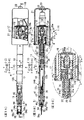
図1は本発明の実施例の試料ホルダが透過型電子顕微鏡(荷電粒子線装置)に装着された状態を示す図である。図2は前記図1の矢印IIで示す部分の拡大図である。図3は前記図2に示す試料ホルダの拡大説明図で、図3Aは平面図、図3Bは図3AのIIIB−IIIB線断面図、図3Cは前記図3Bの矢印IIICで示した部分の拡大図である。図4は前記図3の試料ホルダの先端部分の拡大説明図で、図4Aは平面図であり前記図3Aの矢印IVAで示す部分の拡大説明図、図4Bは前記図4AのIVB−IVB線断面図である。
図5は前記試料ホルダの内端部の説明図で、図5Aは上面図、図5Bは前記図5AのVB−VB線断面図、図5Cは前記図5Bの矢印VCで示した部分の拡大図である。
図6は前記図5AのVI−VI線断面図である。図7は前記図4の試料ホルダの内端部分の上面の斜視図で、試料保持部材本体を取り付ける前の状態を示す図である。図8は前記図7の要部の斜視図である。図9は試料ホルダの内端部分の上面の斜視図で、試料保持部材本体にベリリウム製の試料保持プレートを取り付ける前の状態を示す図である。
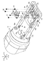
図10は試料ホルダの内端部の説明図で、図10Aは下面図、図10Bは前記図10AのXB−XB線断面図である。図11は前記試料ホルダの内端部分の下面の斜視図で、試料および試料固定プレートを装着する前の状態を示す図である。図12は前記試料ホルダの内端部分の下面の斜視図で、試料および試料固定プレートを装着した後の状態を示す図である。図13は実施例の試料ホルダの試料保持部材を傾斜させる場合の作用を示す図で、図13Aは試料保持部材が水平の状態を示す図、図13Bは試料保持部材の内端部(前端部)が下がるように傾斜した状態を示す図、図13Cは試料保持部材の内端部(前端部)が上がるように傾斜した状態を示す図である。
【0014】
図1において、透過型電子顕微鏡1は、内部を真空に保持された鏡筒2を有し、鏡筒2上端に電子銃3が設けられている。鏡筒2下端部には、観察窓4および、実線で示す観察位置と二点鎖線で示す退避位置との間で移動可能な蛍光板5が設けられている。また、前記蛍光板5の下方には電子顕微鏡画像を撮影するためのフィルムFを撮影位置に配置するための装置が配置されている。
前記電子銃3の下方には荷電粒子線照射調整用レンズ7が配置され、前記蛍光板5の上方には拡大用電子レンズ8が配置されている。そして、前記荷電粒子線照射調整用レンズ7および拡大用電子レンズ8の間には試料装着部としてのゴニオステージGSが設けられている。
ゴニオステージGSは、ホルダ装着孔9aを有する円筒状のホルダ装着部材9を有している。前記円筒状のホルダ装着部材9の軸は、前記荷電粒子線の通路にほぼ直角に交差する方向(X軸方向)に延びている。ホルダ装着部材9は、ゴニオステージGSの球面軸受けにより軸の向きが調節可能に支持されている。
【0015】
図3、図4において、前記ホルダ装着部材9(図1、図2参照)によって支持される試料ホルダHは、前記ホルダ装着孔9a(図1、図2参照)を貫通する円筒状のホルダ外筒11(図3参照)を有している。前記試料ホルダHの軸(すなわち、ホルダ軸)は前記ホルダ装着孔9aの軸と同様に、X軸方向に延びている。ホルダ外筒11は、前記鏡筒2の内側に挿入される導電性の内端側外筒部材12および鏡筒2の外側に配置される導電性の外端側外筒部材13を有している。外端側外筒部材13はその内側面に段部13a(図3B参照)が形成され、後端側部分にはケーブル挿通孔13b(図3B参照)が形成されている。図3Bに示すように、内端側外筒部材12および外端側外筒部材13はそれらの接合部において嵌合し且つ、ネジ14により結合されている。
ホルダ外筒11の内端側外筒部材12の内端部(前記鏡筒2の内部に配置される部分の端部、すなわち、図3A、図3BのX側の端部)外周部には図4に示すOリング16を収容するリング状のOリング収容溝が形成されている。前記Oリング16は、前記ホルダ装着孔9a(図1参照)の内側面に圧接して、Oリング16の前方(X方向)を後方(−X方向)の大気に対して気密に遮断するため部材である。
【0016】
図3において、前記ホルダ外筒11の外端側外筒部材13の外端部(後端部)の外周部にはモータ支持部材17が結合されている。モータ支持部材17はほぼ円筒状の部材であり、その前端(X端)に設けたフランジ17aおよび円筒状部分に形成された前後(X軸方向)に延びるガイド溝17b(図3A参照)を有している。モータ支持部材17の後端にはプレート18が連結されている。プレート18にはX方向移動用モータ19が結合されている。
前記X方向移動用モータ19の周囲は前記モータ支持部材17のフランジ17aに固定されたカバー21により囲まれている。前記カバー21の後端にはケーブル支持部材22が固定されており、ケーブル支持部材22には、前記X方向移動用モータ19への給電ケーブル23が支持されている。
前記X方向移動用モータ19の出力軸24は回転ブロック26に連結されている。回転ブロック26は、円筒状外周側面に形成された雄ネジ26aおよび左方に延びる連結ロッド部26bを有している。回転ブロック26の外周側面の前記雄ネジ26aには円筒状のスライドブロック27の内周側面に形成された雌ネジ27aが螺合している。
【0017】
図3Aにおいて、前記スライドブロック27には被ガイド部材28が固定されている被ガイド部材28は前記ガイド溝17bにスライド移動可能に係合している。前記モータ支持部材17には前記ガイド溝17bの両端にリミットスイッチ29a,29bが支持されており、前記リミットスイッチ29a,29bは、前記被ガイド部材28が当接したときに作動し、被ガイド部材28およびスライドブロック27の前後方向(X軸方向)の位置を検出する。前記リミットスイッチ29a,29bの検出信号は、前記X方向移動用モータ19の駆動制御に使用される。
【0018】
図3Cにおいて、前記外端側外筒部材13には略円筒状のロッドガイド31が固定支持されている。ロッドガイド31の外側面にはケーブル挿通溝31aが形成され、内端部分には前後に延びるガイド溝31bが形成されている。
前記ロッドガイド31の内周面には回転部材32が嵌合しており、回転部材32の後端部分にはロッド部連結孔32aおよび回り止め用溝32bが形成され、前端(内端)側部分にはシャフト螺合用ネジ孔32cが形成されている。
前記ロッド部連結孔32aには前記連結ロッド部26aが嵌合し、連結ロッド部26aに固定された回り止め用ピン26bが前記回り止め用溝32bに相対回転不能且つスライド可能に係合している。
したがって、前記X方向移動用モータ19の出力軸24が回転すると、回転ブロック26が回転し、回転ブロック26の回転に連動して回転部材32が回転するように構成されている。そして、前記回転ブロック26の回転により前記スライドブロック27および被ガイド部材28が前記モータ支持部材17のガイド溝17bに沿って前後(X軸方向)にスライド移動し、それらの移動位置は前記リミットスイッチ29a,29bにより検出される。そして、前記リミットスイッチ29a,29bにより被ガイド部材28の位置が検出されたときには前記X方向移動用モータ19が停止されるように構成されている。
【0019】
前記回転部材32のシャフト螺合用ネジ孔32cには、シャフト33の後端部(−X側端部)が螺合している。
図3B、図3Cにおいて、シャフト33は、その外側面に第1ケーブル挿通溝33aおよび第2ケーブル挿通溝33bが形成され、その前端(内端)部にはハーメチックシール収容孔33c(図3B、図4参照)が形成されている。図4において、前記ハーメチックシール収容孔33cには、その内端(前端)部に、段部33d、ケーブル挿通溝33e、33f(図4B参照)が形成されている。
また、図4に示すように、シャフト33の内端部(前端部)外周面にはOリング34を収容するOリング収容溝が形成されている。Oリング34は、前記内端側外筒部材12内周面に密着して、その後側部分(外端側部分)および前側部分(内端側部分)の空間を気密に遮断している。
シャフト33には回り止め用ピン35が固定されており、回り止め用ピン35(図3B、図3C参照)は前記ガイド溝31bにスライド可能且つ相対回転不能に係合している。
【0020】
図3B、図3Cにおいて、前記シャフト33には、そのシャフト33上に固定支持された固定プレート36およびシャフト33の軸方向に沿ってスライド移動可能な移動プレート37が支持されており、それらの間には圧縮ばね38が配置されている。前記移動プレート37は外端側外筒部材13の内側面に形成された段部13aに当接しており、固定プレート36およびシャフト33は前記圧縮ばね38により常時後方(−X方向)に押圧されている。前記移動プレート37、固定プレート36および圧縮ばね38は、前記シャフト33の後端部(−X側端部)およびシャフト螺合用ネジ孔32cの螺合部分のガタを吸収する機能を有している。
【0021】
図3Cにおいて、ケーブルKは、ケーブル挿通溝前記ケーブル挿通孔13bおよびケーブル挿通孔溝31aを通って外端側外筒部材13内側に導入される。図3Bにおいて、前記ケーブルKは、前記シャフト33に形成された第1ケーブル挿通溝33a、第2ケーブル挿通溝33bを通って前記ハーメチックシール収容孔33c内に導入される。
図4において、前記シャフト33内端部(前端部)のハーメチックシール収容孔33cの前記段部33dにはハーメチックシール39が固定されている。ハーメチックシール39には外端面(後端面)および内端面(前端面)にそれぞれ4本の端子が設けられており、外端面の4本の端子には前記ケーブルKの複数の接続線が接続されている。前記複数の接続線は、アース用接続線、後述の圧電体のX変位用接続線、および試料の加熱等の際に使用される加熱用接続線等である。
【0022】
図4において、前記シャフト33の内端(前端)には圧電体支持部材41が固定されている。圧電体支持部材41は、中央に大径のフランジ部41a有し、その上部に接続線挿通溝41bを有し、下部にアース接続部材支持溝41cを有している。また、圧電体支持部材41には軸方向(前後)に延びる真空引き用孔41dが形成されている。
前記圧電体支持部材41のアース接続部材支持溝41cには、導電性のアース接続部材42(図4B参照)が固定されている。アース接続部材42は図4Bに示すように、フランジ部42aおよび部分円筒部42bを有している。図4Bから分かるように、導電性のアース接続部材42の部分円筒部42bの外側面(部分円筒面)は、前記圧電体支持部材41の内端部(前端部)の外周面と同一の半径を有している。そして、前記圧電体支持部材41の内端部(前端部)の外周面およびアース接続部材42の部分円筒部42bの外側面(部分円筒面)により円筒状の圧電体43の基端部が嵌合する円筒面が形成されている。前記アース接続部材42には前記ケーブルKのアース用接続線が接続される。
前記符号33〜42で示された要素によりホルダ内側移動部材(33〜42)が構成されている。
前記ホルダ内側移動部材(33〜42)は前記X方向移動用モータ19および前記符号24〜32で示された要素(19,24〜32)により、X軸方向に移動(粗動)制御される。
【0023】
前記ホルダ内側移動部材(33〜42)により、基端部(外端部)が支持された円筒状の圧電体43は、その内面にアース用電極(図示せず)が形成されており、表面にはX軸方向駆動用電極(図示せず)が形成されている。前記圧電体43は、前記X軸方向駆動用電極に印加する電圧によりX軸方向に伸縮可能である。そして、印加電圧を制御することにより前記圧電体43の先端部(内端部)の位置を精密に制御できるようになっている。
前記圧電体43の内端には円筒部44aおよびフランジ部44bを有する連結部材44(図4B参照)が固定されている。連結部材44には傾斜用当接部材46の外端部が固定されている。傾斜用当接部材46は、図4に示すように、前方に突出する突出部を有し、その先端にはボール46a(図9、図11参照)が装着されている。
前記符号33〜46で示された要素により傾斜位置調節部材(33〜46)が構成されている。
【0024】
図4、図5Bにおいて、前記内端側外筒部材12の内端(前端)部には試料保持部材装着部材51が固定されている。前記試料保持部材装着部材51は、後端側の円筒状の被嵌合部52(図5B参照)を有する枠支持部材53と、前記枠支持部材53の前端面から前方(X方向)に突出する試料保持部材支持枠54とを有している。
図5〜図7、図9において、前記枠支持部材53には開口53aが形成されている。前記開口53aは、前記傾斜用当接部材46の前方突出部が貫通するための開口である。
【0025】
前記試料保持部材支持枠54は、開口54aを形成するように左右に離れて前後方向に延びる平行な一対の側枠54b,54bと前記一対の側枠54b,54bの前端部を連結する前端枠54cとを有している。
前記開口54aの外端側部分(−X側部分)には傾斜部材56が配置されており、前記傾斜部材56は前記試料保持部材支持枠54によりY軸方向に沿う傾斜軸57回りに傾斜可能に支持されている。前記傾斜部材56は、前記傾斜軸57より下方に突出する移動部材被当接部56aと、内端部(X側端部)に設けられた左右一対の水平なピンにより構成された保持部材係合部材56b,56b(図7参照)とを有している。前記移動部材被当接部56aの後面(−X側面)には前記傾斜位置調節部材(33〜46)の傾斜用当接部材46前端に設けたボール46aが当接している。
【0026】
図6、図11、図12において、前記試料収容部66には試料S、スペーサ67およびベリリウム製の試料固定プレート68が収容される。
前記試料固定プレート68はその中央部で且つ前記プレート側貫通孔63aに対応して形成された試料固定プレート側貫通孔68a1を有するリング状の試料固定部68aと、前記試料固定部68aの中心線に沿って左右方向に延びる被押圧部68b,68bとを有している。
【0027】
図5、図8において、前記被支持部58a,58aと被係合部58bとの間の外側部にはバネ係止ネジ61,61が固着されており、前記バネ係止ネジ61,61と前記傾斜部材56の傾斜軸57との間にはそれぞれ前記試料保持部材本体58の後端を下方に下げるように押圧する線状バネ部材62,62が設けられている。前記各線状バネ部材62は前記試料保持部材本体58の後端を前記傾斜ネジ58回りに下方に回動させるように作用する。
前記試料保持部材本体58に係合する傾斜部材56の先端が下方に回動しようとするが、前記移動部材被当接部56aには前記ボール46aが当接しているので、回動しない。このため、前記傾斜部材56および前記傾斜部材56と係合している試料保持部材本体58は前記移動部材被当接部56aが前記ボール46aに当接する位置に保持される。したがって、前記傾斜位置調節部材(33〜46)の傾斜用当接部材46前端に設けたボール46aの位置を前後方向に調節することにより前記試料保持部材本体58の傾斜を調節することができる。
前記符号11〜57,62で示された要素により試料保持部材装着ホルダ(11〜57,62)が構成されている。
【0028】
図9において、前記プレート装着部58dの上面の試料保持プレート装着面58eにはベリリウム製の試料保持プレート63がネジ64によって固定される。
前記試料保持プレート63の中央部にはプレート側貫通孔63aが形成されており、前記プレート側貫通孔63aの左方(Y方向)側にはX線通過用の通路を形成するための切除部(図6、図5C参照)63bが設けられている。
前記プレート側貫通孔63aは前記試料保持プレート装着面58e上では前記本体側貫通孔58fと対応する位置に配置され、前記本体側貫通孔58fの内径より小さく形成されている。したがって、図11に示すように試料保持プレート装着面58eの下面側において、前記プレート側貫通孔63aの開口部外周側の面と前記試料保持部材本体58中央の本体側貫通孔58fから試料収容部66が形成されることになる。
【0029】
図6、図11、図12において、前記試料保持部材本体58の下面の試料収容部66には試料S、スペーサ67およびベリリウム製の試料固定プレート68が収容される。
前記試料固定プレート68はその中央部で且つ前記プレート側貫通孔63aに対応して形成された試料固定プレート側貫通孔68a1を有するリング状の試料固定部68aと、前記試料固定部68aの中心線に沿って左右方向に延びる被押圧部68b,68bとを有している。
【0030】
前記試料保持部材本体58が前記試料保持部材支持枠54に装着された状態では、前記傾斜ネジ59,59はそれらの軸線が前記筒状のホルダ装着部材9の軸線と交差するように配置される。
また、前記試料収容部66に収容された試料S表面は前記傾斜ネジ59,59の軸線上に配置されるようになっている。試料Sをこのような位置に装着することにより、試料保持部材本体58を前記傾斜ネジ59,59回りに回動させたり、前記ホルダ装着部材9の軸線回りに回動させた場合に、試料S表面のビーム入射位置を移動させないようにすることができる。
【0031】
図11、図12において、前記試料保持部材本体58の各板バネ保持部58cの下面にはネジ69,69により板バネ71が水平方向(左右方向)に回動可能に保持されている。前記板バネ71の中央部にはピン被係止孔71aが形成されている。
前記板バネ保持部58cと前記試料固定プレート収容凹部58g,58gの両端部との間には板バネ係止ピン72が固定されており、前記板バネ係止ピン72は前記板バネ71のピン被係止孔71aに係止するようになっている。この状態では前記板バネ71の先端部が前記試料収容部66に収容された試料固定プレート68の中心線に沿って左右に伸びる被押圧部68bを押圧する。このため、前記試料固定プレート68に固定される試料Sは、前記試料Sを通る線上で押圧されるようになっている。
なお、前記符号58〜61,63〜71で示された要素により試料保持部材(58〜61,63〜71)が構成されている。また、前記試料保持部材装着ホルダ(11〜57,62)および試料保持部材(58〜61,63〜71)から試料ホルダHが構成されている。
【0032】
(実施例の作用)
図7〜図12において、試料保持部材本体58の上面の試料保持プレート装着面58eにはベリリウム製の試料保持プレート63が装着される。前記試料保持部材本体58の下面の試料収容部66に試料S、スペーサ67および試料固定プレート68を収容する。
試料保持部材本体58の内端側に支持されている板バネ71,71の先端部を前記水平位置の試料固定プレート68の左右両側の被押圧部68b,68b側へ回動させて、板バネ71,71を板バネ保持部58cに保持する。このとき、板バネ71,71のピン被係止孔71aに前記板バネ係止ピン72が係止されて、板バネ71,71が試料固定プレート68の被押圧部68b,68bを押圧する。前記試料支持枠54に装着された試料保持部材本体58の被係合部58b,58bは、前記試料保持部材支持枠54に支持された傾斜部材56の保持部材係合部材56b,56bと係合する。
【0033】
図1、図2において試料ホルダHのホルダ外筒11は、鏡筒2に設けたゴニオステージGSの円筒状のホルダ装着部材9のホルダ装着孔9aに装着される。
前記ゴニオステージGSのホルダ装着孔9aにより支持された試料ホルダHをホルダ外筒11の軸(ホルダ軸)に沿ってスライドまたは前記ホルダ装着部材9をゴニオステージGSの球面軸受けにより回動させることにより、軸方向の位置または試料ホルダHのホルダ軸の向き(水平方向)およびホルダ軸(X軸)回りの回転位置を調節することができる。
【0034】
図13において、前記試料SをY軸回りに傾斜させる場合、前記傾斜位置調節部材(33〜46)の内端の傾斜用当接部材46前端に設けたボール46aを前記傾斜部材56の移動部材被当接部56aに当接させた状態で前記傾斜位置調節部材(33〜46)のX軸方向の位置を調節すると、前記傾斜部材56が傾斜軸57回りに傾斜する。この傾斜部材56の傾斜に応じて前記試料保持部材本体58が前記傾斜用ネジ59,59の軸線回りに回動する。したがって、試料保持部材本体58に保持された試料Sは、Y軸方向に沿う傾斜用ネジ59,59の軸線回りに回転位置が調節される。
【0035】
前記傾斜用当接部材46前端に設けたボール46aの位置を前方へ移動させて前記傾斜部材56の移動部材被当接部56aを前方へ押圧すると図13Bに示すように傾斜部材56の前端部が上方へ移動し、前記試料保持部材本体58の後端を持ち上げ前記試料保持部材本体58の前端部が下がり、試料Sの中心から前側の部分が下がるように傾斜する。前記傾斜用当接部材46前端に設けたボール46aの位置を後方へ移動させると、前記傾斜部材56の移動部材被当接部56aに当接しないので、前記試料保持部材本体58の後端が下方に下がるように押圧する線状バネ部材62,62により図13Cに示すように前記試料保持部材本体58の後端および傾斜部材56の前端が下がり試料Sの中心から前側の部分が上がるように傾斜する。
また、ホルダ外筒11をX軸方向に移動させることにより試料SのX軸方向の位置を調節することが可能である。
【0036】
前記試料固定プレート68の被押圧部68b,68bを収容する試料固定プレート収容凹部58g,58gは、前記本体側貫通孔58fを横切って且つ両端部が前記本体側貫通孔58fを挟んで前記本体側貫通孔58fから離れた位置に配置されている。したがって、試料固定プレート68が試料収容部66(本体側貫通孔58f)に保持されている試料Sを横切るように固定する。このため、前記試料Sの固定が確実に行える。
前記ベリリウム製の試料固定プレート68は前記板バネ71によって押圧されていて前記図14に示す従来の試料ホルダのようにネジで止める必要がないので、前記ベリリウム製の試料固定プレートはネジで強く締め付けて割れることがない。
また、前記試料固定プレ−ト68を押圧する板バネ71はベリリウム製でなくても試料Sの位置から離れていて且つ前記試料ホルダHの下面に配置されているので、X線分析のときX線照射を受けずX線分析に悪影響を与えることがない。
【0037】
(変更例)
以上、本発明の実施例を詳述したが、本発明は、前記実施例に限定されるものではなく、特許請求の範囲に記載された本発明の要旨の範囲内で、種々の変更を行うことが可能である。本発明の変更実施例を下記に例示する。
(H01)前記実施例の試料Sを試料Sの左右方向に押圧して固定していたが試料Sの前記試料保持プレート装着部58dの対角線(斜め)方向に押圧して固定することも可能である。
(H02)前記試料収容部66は前記試料保持プレート58下面に形成することも可能である。
(H03)前記傾斜部材56を所定の傾斜位置に保持するように作用する線状バネ62は、前記傾斜部材56を所定の傾斜位置に弾性的に保持する構成または所定方向に向けて傾斜させる弾性力を付与する構成とすることが可能である。
(H04)本発明の試料ホルダは透過型電子顕微鏡以外の他の荷電粒子線装置にも使用可能である。
【0038】
【発明の効果】
前述の本発明の試料ホルダは、下記の効果を奏することができる。
(E01)丈夫で試料を確実に固定できるとともに、X線分析に使用した場合に悪影響を与えることがなくX線分析ができる。
【図面の簡単な説明】
【図1】 図1は本発明の実施例の試料ホルダが透過型電子顕微鏡(荷電粒子線装置)に装着された状態を示す図である。
【図2】 図2は前記図1の矢印IIで示す部分の拡大図である。
【図3】 図3は前記図2に示す試料ホルダの拡大説明図で、図3Aは平面図、図3Bは図3AのIIIB−IIIB線断面図、図3Cは前記図3Bの矢印IIICで示した部分の拡大図である。
【図4】 図4は前記図3の試料ホルダの先端部分の拡大説明図で、図4Aは平面図であり前記図3Aの矢印IVAで示す部分の拡大説明図、図4Bは前記図4AのIVB−IVB線断面図である。
【図5】 図5は前記試料ホルダの内端部の説明図で、図5Aは上面図、図5Bは前記図5AのVB−VB線断面図、図5Cは前記図5Bの矢印VCで示した部分の拡大図である。
【図6】 図6は前記図5AのVI−VI線断面図である。
【図7】 図7は前記図4の試料ホルダの内端部分の上面の斜視図で、試料保持部材本体を取り付ける前の状態を示す図である。
【図8】 図8は前記図7の要部の斜視図である。
【図9】 図9は試料ホルダの内端部分の上面の斜視図で、試料保持部材本体にベリリウム製の試料保持プレートを取り付ける前の状態を示す図である。
【図10】 図10は試料ホルダの内端部の説明図で、図10Aは下面図、図10Bは前記図10AのXB−XB線断面図である。
【図11】 図11は前記試料ホルダの内端部分の下面の斜視図で、試料および試料固定プレートを装着する前の状態を示す図である。
【図12】 図12は前記試料ホルダの内端部分の下面の斜視図で、試料および試料固定プレートを装着した後の状態を示す図である。
【図13】 図13は実施例の試料ホルダの試料保持部材を傾斜させる場合の作用を示す図で、図13Aは試料保持部材が水平の状態を示す図、図13Bは試料保持部材の内端部(前端部)が下がるように傾斜した状態を示す図、図13Cは試料保持部材の内端部(前端部)が上がるように傾斜した状態を示す図である。
【図14】 図14は従来のX線分析で使用される試料ホルダの要部斜視図である。
【符号の説明】
S…試料、
2…鏡筒、9…ホルダ装着部材、11…ホルダ外筒、58…試料保持部材本体、58c…板バネ保持部、58e…試料保持プレート装着面、58f…本体側貫通孔、58g,58g…試料固定プレート収容凹部、63…試料保持プレート、63a…プレート側貫通孔、68…試料固定プレート、68a1…試料固定プレート側貫通孔、68b,68b…被押圧部、71…板バネ[0001]
BACKGROUND OF THE INVENTION
The present invention relates to a sample holder that holds a sample in a passage of a charged particle beam irradiated from a charged particle beam source (electron gun, ion gun, etc.) of a charged particle beam apparatus such as an electron microscope that performs microscopic analysis work on the sample, In particular, the present invention relates to a sample holder suitable for performing X-ray analysis.
[0002]
[Prior art]
Conventionally, as a sample holder used for X-ray analysis, a light element material (mainly beryllium Be) outside the X-ray detection range is used in the peripheral portion of the sample.
As a sample holder used for X-ray analysis, the following technique (J01) is conventionally known.
(J01) Technology shown in FIG.
FIG. 14 is a perspective view of a main part of a sample holder used in the conventional X-ray analysis.
In FIG. 14, a sample holding
The sample holding member main body 02 is configured by integrally connecting a
A plate through
[0003]
A sample S adhering to the grid mesh surface is accommodated in the sample accommodating recess 03b, and a Be (beryllium)
[0004]
[Problems to be solved by the invention]
Since the
In view of the circumstances described above, the present invention has the following description as a problem.
(O01) To provide a sample holder that is strong and can securely fix a sample and that does not adversely affect the X-ray analysis when used for the X-ray analysis.
[0005]
[Means for Solving the Problems]
Next, the present invention devised to solve the above problems will be described. Elements of the present invention are parenthesized with reference numerals of elements of the embodiments in order to facilitate correspondence with elements of the embodiments described later. Append what is enclosed in brackets.
The reason why the present invention is described in correspondence with the reference numerals of the embodiments described later is to facilitate understanding of the present invention, and not to limit the scope of the present invention to the embodiments.
[0006]
(Invention)
(First invention)
In order to solve the above problem,FirstThe sample holder of the invention is characterized by having the following requirements:
(A01) A lens barrel (2) arranged so as to surround the outside of the path of the charged particle beam along the Z-axis among the Z-axis extending vertically and vertically, the X-axis extending forward and backward, and the Y-axis extending horizontally ) Is supported by a cylindrical holder mounting member (9) penetrating in the X-axis direction so as to be rotatable about the X-axis and slidable along the X-axis,
(A02) A sample holding plate mounting surface (58e) provided at the inner end of the holder outer cylinder (11) and having a main body side through hole (58f) used for holding the sample (S) at the center. A leaf spring holding portion (58c) provided in the vicinity of a position away from the main body side through hole (58f) with the main body side through hole (58f) sandwiched on the lower surface and the main body side through hole (on the upper surface) 58f) and sample fixing plate receiving recesses (58g, 58g) that are formed across the main body side through hole (58f) with both end portions sandwiching the main body side through hole (58f). A sample holding member body (58) having,
(A03) A sample holding plate (63) made of beryllium which is mounted on the sample holding plate mounting surface (58e) and has a plate side through hole (63a) smaller than the main body side through hole (58f);
(A 04 ′) A ring-shaped sample fixing portion (68a) having a sample fixing plate side through hole (68a1) formed corresponding to the plate side through hole (63a);
It is accommodated in the sample fixing plate accommodating recess (58g, 58g) and is disposed in the vicinity of the leaf spring holding portion (58c).And it extends toward the outside from the outer peripheral portion of the ring-shaped sample fixing portion (68a).Pressed part (68b, 68b)When,
A sample fixing plate (68) made of beryllium having
(A05) A leaf spring (71) held by the leaf spring holding portion (58c) and pressing the pressed portions (68b, 68b) of the sample fixing plate (68).
[0007]
(1st inventionAction)
With the above configuration1st inventionIn the sample holder, the sample holding member main body (58) is provided at the inner end of the holder outer cylinder (11), and the sample holding plate mounting surface (58e) on the sample holding plate mounting surface (58e) on the upper surface thereof. A sample holding plate (63) made of beryllium in which a plate side through hole (63a) smaller than the central body side through hole (58f) is formed is mounted, and the main body is formed from the lower surface side of the sample holding member main body (58). The sample (S) is accommodated and held in the side through hole (58f).
A sample fixing plate side through hole (68a1) was formed corresponding to the plate side through hole (63a) of the sample holding plate (63).It has a ring-shaped sample fixing part (68a)The sample fixing plate (68) made of beryllium crosses the main body side through hole (58f), and both ends thereof are located away from the main body side through hole (58f) with the main body side through hole (58f) interposed therebetween. It is accommodated in the arranged sample fixing plate accommodating recess (58g, 58g).
The leaf spring (71) held by the leaf spring holding portion (58c) of the sample holding member main body (58) is the same as that of the sample fixing plate (68).The ring-shaped sample fixing portion (68a) extends outward from the outer peripheral portion.The pressed parts (68b, 68b) are pressed.
[0008]
The cylindrical holder mounting member (9) surrounds the outside of the charged particle beam path along the Z axis among the Z axis extending vertically and vertically, the X axis extending front and rear, and the Y axis extending right and left. The holder outer cylinder (11) of the sample holder holding the sample (S) is rotated around the X axis by the cylindrical holder mounting member (9), penetrating the arranged lens barrel (2) in the X-axis direction. Supported and slidable along the X axis.
Of the sample fixing plate (68)The ring-shaped sample fixing portion (68a) extends outward from the outer peripheral portion.The sample fixing plate accommodating recesses (58g, 58g) for accommodating the pressed parts (68b, 68b) cross the main body side through hole (58f) and both ends sandwich the main body side through hole (58f). It arrange | positions in the position away from the main body side through-hole (58f). Therefore, the sample fixing plate (68) is fixed so as to cross the sample (S) held in the main body side through hole (58f). For this reason, the sample (S) can be reliably fixed.
Further, since the beryllium sample fixing plate (68) is pressed by the leaf spring (71), it does not need to be screwed as in the conventional sample holder shown in FIG. Therefore, the beryllium sample fixing plate (68) is not broken by being tightened with screws. Furthermore, since the leaf spring (71) is held at a position on the lower surface of the sample holding member main body (58) and away from the main body side through hole (58f) where the sample (S) is held, the sample (S) When the analysis is performed by irradiating X-rays, the X-ray analysis result is not adversely affected without receiving the X-ray irradiation.
[0012]
DETAILED DESCRIPTION OF THE INVENTION
【Example】
Next, specific examples (examples) of the form of the sample holder of the present invention will be described with reference to the drawings, but the present invention is not limited to the following examples.
In order to facilitate understanding of the following description, in the drawings, the front-rear direction is the X-axis direction, the left-right direction is the Y-axis direction, the up-down direction is the Z-axis direction, and arrows X, -X, Y, -Y, The directions indicated by Z and -Z or the indicated sides are defined as front, rear, left, right, upper, lower, or front, rear, left, right, upper, and lower, respectively.
In the figure, “•” in “○” means an arrow heading from the back of the page to the front, and “×” in “○” is the front of the page. It means an arrow pointing from the back to the back.
[0013]
(Example)
FIG. 1 is a view showing a state in which a sample holder according to an embodiment of the present invention is mounted on a transmission electron microscope (charged particle beam apparatus). FIG. 2 is an enlarged view of a portion indicated by an arrow II in FIG. 3 is an enlarged explanatory view of the sample holder shown in FIG. 2, FIG. 3A is a plan view, FIG. 3B is a sectional view taken along line IIIB-IIIB in FIG. 3A, and FIG. 3C is an enlarged view of the portion indicated by arrow IIIC in FIG. FIG. 4 is an enlarged explanatory view of the tip portion of the sample holder of FIG. 3, FIG. 4A is a plan view, an enlarged explanatory view of a portion indicated by an arrow IVA in FIG. 3A, and FIG. 4B is an IVB-IVB line in FIG. It is sectional drawing.
5 is an explanatory view of the inner end of the sample holder, FIG. 5A is a top view, FIG. 5B is a cross-sectional view taken along line VB-VB in FIG. 5A, and FIG. 5C is an enlarged view of the portion indicated by arrow VC in FIG. FIG.
6 is a cross-sectional view taken along the line VI-VI in FIG. 5A. FIG. 7 is a perspective view of the upper surface of the inner end portion of the sample holder of FIG. 4 and shows a state before the sample holding member main body is attached. FIG. 8 is a perspective view of the main part of FIG. FIG. 9 is a perspective view of the upper surface of the inner end portion of the sample holder, showing a state before a beryllium sample holding plate is attached to the sample holding member body.
FIG. 10 is an explanatory view of the inner end portion of the sample holder, FIG. 10A is a bottom view, and FIG. 10B is a cross-sectional view taken along the line XB-XB in FIG. 10A. FIG. 11 is a perspective view of the lower surface of the inner end portion of the sample holder, showing a state before the sample and the sample fixing plate are mounted. FIG. 12 is a perspective view of the lower surface of the inner end portion of the sample holder, showing a state after the sample and the sample fixing plate are mounted. FIG. 13 is a diagram showing an operation when the sample holding member of the sample holder of the embodiment is tilted. FIG. 13A is a view showing the horizontal state of the sample holding member, and FIG. 13B is an inner end portion (front end portion) of the sample holding member. FIG. 13C is a diagram illustrating a state in which the inner end portion (front end portion) of the sample holding member is tilted so as to rise.
[0014]
In FIG. 1, a
A charged particle beam
The gonio stage GS has a cylindrical
[0015]
3 and 4, the sample holder H supported by the holder mounting member 9 (see FIGS. 1 and 2) is outside the cylindrical holder penetrating the
The inner end portion of the inner end side
[0016]
In FIG. 3, a
The periphery of the
An
[0017]
In FIG. 3A, a guided
[0018]
In FIG. 3C, a substantially
A rotating
The connecting
Accordingly, when the
[0019]
The rear end portion (−X side end portion) of the
3B and 3C, the
As shown in FIG. 4, an O-ring housing groove for housing the O-
An
[0020]
3B and 3C, the
[0021]
3C, the cable K is introduced into the outer end side outer
In FIG. 4, a
[0022]
In FIG. 4, a
A conductive ground connection member 42 (see FIG. 4B) is fixed to the ground connection member support groove 41c of the piezoelectric
The elements indicated by the
The holder inner moving members (33 to 42) are controlled to move (coarsely move) in the X axis direction by the X
[0023]
The cylindrical
A connecting member 44 (see FIG. 4B) having a
Inclined position adjusting members (33 to 46) are constituted by the elements indicated by the
[0024]
4 and 5B, a sample holding
5 to 7 and 9, the
[0025]
The sample holding
An
[0026]
6, 11, and 12,The sample container 66Contains a sample S, a
The
[0027]
5 and 8, spring locking screws 61, 61 are fixed to the outer portion between the supported
The tip of the
A sample holding member mounting holder (11-57, 62) is constituted by the elements indicated by the reference numerals 11-57, 62.
[0028]
In FIG. 9, a
A plate-side through
The plate side through
[0029]
6, 11, and 12, the
The
[0030]
In a state where the sample holding member
Further, the surface of the sample S accommodated in the
[0031]
11 and 12, a
A plate
A sample holding member (58-61, 63-71) is constituted by the elements indicated by the reference numerals 58-61, 63-71. The sample holder H is composed of the sample holding member mounting holders (11 to 57, 62) and the sample holding members (58 to 61, 63 to 71).
[0032]
(Operation of Example)
7 to 12, a
The leaf springs 71 and 71 supported on the inner end side of the sample holding member
[0033]
1 and 2, the holder outer cylinder 11 of the sample holder H is mounted in the
The sample holder H supported by the
[0034]
In FIG. 13, when the sample S is tilted about the Y axis, the
[0035]
When the position of the
In addition, the position of the sample S in the X-axis direction can be adjusted by moving the holder outer cylinder 11 in the X-axis direction.
[0036]
The sample fixing
Since the beryllium
Further, even if the
[0037]
(Example of change)
As mentioned above, although the Example of this invention was explained in full detail, this invention is not limited to the said Example, A various change is performed within the range of the summary of this invention described in the claim. It is possible. Modified embodiments of the present invention are illustrated below.
(H01) The sample S of the above embodiment is pressed and fixed in the left-right direction of the sample S, but it is also possible to press and fix the sample S in the diagonal (diagonal) direction of the sample holding plate mounting portion 58d. is there.
(H02) The
(H03) The
(H04) The sample holder of the present invention can also be used for other charged particle beam devices other than the transmission electron microscope.
[0038]
【The invention's effect】
The sample holder of the present invention described above can achieve the following effects.
(E01) It is strong and can securely fix a sample, and can be used for X-ray analysis without causing any adverse effects.
[Brief description of the drawings]
FIG. 1 is a diagram showing a state in which a sample holder according to an embodiment of the present invention is mounted on a transmission electron microscope (charged particle beam apparatus).
FIG. 2 is an enlarged view of a portion indicated by an arrow II in FIG.
3 is an enlarged explanatory view of the sample holder shown in FIG. 2, FIG. 3A is a plan view, FIG. 3B is a sectional view taken along line IIIB-IIIB in FIG. 3A, and FIG. 3C is indicated by an arrow IIIC in FIG. FIG.
4 is an enlarged explanatory view of a tip portion of the sample holder in FIG. 3, FIG. 4A is a plan view, an enlarged explanatory view of a portion indicated by an arrow IVA in FIG. 3A, and FIG. 4B in FIG. It is IVB-IVB line sectional drawing.
5 is an explanatory view of the inner end of the sample holder, FIG. 5A is a top view, FIG. 5B is a cross-sectional view taken along line VB-VB in FIG. 5A, and FIG. 5C is indicated by an arrow VC in FIG. FIG.
FIG. 6 is a cross-sectional view taken along the line VI-VI in FIG. 5A.
7 is a perspective view of the top surface of the inner end portion of the sample holder of FIG. 4, showing a state before the sample holding member main body is attached. FIG.
FIG. 8 is a perspective view of the main part of FIG.
FIG. 9 is a perspective view of the top surface of the inner end portion of the sample holder, showing a state before a beryllium sample holding plate is attached to the sample holding member body.
10 is an explanatory view of the inner end of the sample holder, FIG. 10A is a bottom view, and FIG. 10B is a cross-sectional view taken along line XB-XB in FIG. 10A.
FIG. 11 is a perspective view of the lower surface of the inner end portion of the sample holder, showing a state before the sample and the sample fixing plate are mounted.
FIG. 12 is a perspective view of the lower surface of the inner end portion of the sample holder, showing a state after the sample and the sample fixing plate are mounted.
FIG. 13 is a view showing an operation when the sample holding member of the sample holder of the embodiment is inclined, FIG. 13A is a view showing the horizontal state of the sample holding member, and FIG. 13B is an inner end of the sample holding member. FIG. 13C is a diagram showing a state where the inner end portion (front end portion) of the sample holding member is inclined so as to rise.
FIG. 14 is a perspective view of a main part of a sample holder used in a conventional X-ray analysis.
[Explanation of symbols]
S ... Sample,
DESCRIPTION OF
Claims (1)
(A01)互いに垂直な上下に延びるZ軸、前後に延びるX軸、および左右に延びるY軸のうちのZ軸に沿った荷電粒子線の通路の外側を囲むように配置された鏡筒をX軸方向に貫通する筒状のホルダ装着部材により、X軸回りに回転可能且つX軸に沿ってスライド可能に支持されたホルダ外筒、
(A02)前記ホルダ外筒の内端部に設けられ、中央部に試料保持に使用される本体側貫通孔が形成された試料保持プレート装着面を上面に有し、下面に前記本体側貫通孔を挟んで前記本体側貫通孔から離れた位置の近傍に設けられた板バネ保持部と前記本体側貫通孔を横切って形成され且つ両端部が前記本体側貫通孔から離れた位置に配置された試料固定プレート収容凹部とを有する試料保持部材本体、
(A03)前記試料保持プレート装着面に装着されるとともに前記本体側貫通孔よりも小さなプレート側貫通孔が形成されたベリリウム製の試料保持プレート、
(A04′)前記プレート側貫通孔に対応して形成された試料固定プレート側貫通孔を有するリング状の試料固定部と、
前記試料固定プレート収容凹部に収容されるとともに前記板バネ保持部近傍に配置され且つ前記リング状の試料固定部の外周部分から外側へ向けて延びる被押圧部と、
を有するベリリウム製の試料固定プレート、
(A05)前記板バネ保持部に保持され且つ前記試料固定プレートの被押圧部を押圧する板バネ。Specimen holder with the following requirements,
(A01) A lens barrel arranged so as to surround the outside of the path of the charged particle beam along the Z-axis among the Z-axis extending vertically and vertically, the X-axis extending forward and backward, and the Y-axis extending horizontally A holder outer cylinder supported by a cylindrical holder mounting member penetrating in the axial direction so as to be rotatable around the X axis and slidable along the X axis;
(A02) A sample holding plate mounting surface provided on the inner end of the holder outer cylinder and having a main body side through hole used for holding a sample at the center is formed on the upper surface, and the main body side through hole is formed on the lower surface. Between the leaf spring holding portion provided in the vicinity of the position away from the main body side through hole and the main body side through hole, and both end portions are disposed at positions away from the main body side through hole. A sample holding member main body having a sample fixing plate receiving recess,
(A03) a sample holding plate made of beryllium which is mounted on the sample holding plate mounting surface and has a plate side through hole smaller than the main body side through hole;
(A04 ′) a ring-shaped sample fixing portion having a sample fixing plate side through hole formed corresponding to the plate side through hole;
A pressed portion that is housed in the sample fixing plate housing recess and is disposed in the vicinity of the leaf spring holding portion and extends outward from an outer peripheral portion of the ring-shaped sample fixing portion;
A sample fixing plate made of beryllium,
(A05) A leaf spring that is held by the leaf spring holding portion and presses the pressed portion of the sample fixing plate.
Priority Applications (1)
| Application Number | Priority Date | Filing Date | Title |
|---|---|---|---|
| JP00701198A JP4063379B2 (en) | 1998-01-16 | 1998-01-16 | Sample holder |
Applications Claiming Priority (1)
| Application Number | Priority Date | Filing Date | Title |
|---|---|---|---|
| JP00701198A JP4063379B2 (en) | 1998-01-16 | 1998-01-16 | Sample holder |
Publications (2)
| Publication Number | Publication Date |
|---|---|
| JPH11204074A JPH11204074A (en) | 1999-07-30 |
| JP4063379B2 true JP4063379B2 (en) | 2008-03-19 |
Family
ID=11654120
Family Applications (1)
| Application Number | Title | Priority Date | Filing Date |
|---|---|---|---|
| JP00701198A Expired - Fee Related JP4063379B2 (en) | 1998-01-16 | 1998-01-16 | Sample holder |
Country Status (1)
| Country | Link |
|---|---|
| JP (1) | JP4063379B2 (en) |
Families Citing this family (6)
| Publication number | Priority date | Publication date | Assignee | Title |
|---|---|---|---|---|
| JP4233948B2 (en) * | 2003-07-24 | 2009-03-04 | 日本電子株式会社 | Sample holder |
| JP4898355B2 (en) * | 2005-09-20 | 2012-03-14 | 裕也 宮崎 | Sample holder |
| JP5111042B2 (en) * | 2007-10-02 | 2012-12-26 | 日本電子株式会社 | Cartridge for electron microscope |
| JP5458742B2 (en) * | 2009-08-21 | 2014-04-02 | 株式会社島津製作所 | Electron beam microanalyzer |
| JP6326341B2 (en) * | 2014-09-29 | 2018-05-16 | 日本電子株式会社 | Sample holder and electron microscope |
| CN104637765B (en) * | 2015-02-15 | 2016-08-24 | 北京工业大学 | A kind of transmission electron microscope double shaft tilting sample stage |
-
1998
- 1998-01-16 JP JP00701198A patent/JP4063379B2/en not_active Expired - Fee Related
Also Published As
| Publication number | Publication date |
|---|---|
| JPH11204074A (en) | 1999-07-30 |
Similar Documents
| Publication | Publication Date | Title |
|---|---|---|
| US7291847B2 (en) | Specimen tip and tip holder assembly | |
| US7639778B2 (en) | Mammographic apparatus, breast compression plate, and breast fixing method | |
| US7672425B2 (en) | Real-time digital X-ray imaging apparatus | |
| US6412978B1 (en) | X-ray diagnostic apparatus | |
| JP4063379B2 (en) | Sample holder | |
| JP2011514641A (en) | Sample holder assembly | |
| KR101443654B1 (en) | Focus adjusting device of camera module and Focus adjusting methods using the same | |
| JP3986778B2 (en) | Holder support device | |
| JPH11185686A (en) | Sample holder, sample holding member fitting holder, and sample holding member | |
| JP2006012795A (en) | Transmission electron microscope | |
| KR102493518B1 (en) | Sample stage | |
| Beetz et al. | Apparatus for x-ray diffraction microscopy and tomography of cryo specimens | |
| JP3472058B2 (en) | Sample holder and sample holding device | |
| JP6326341B2 (en) | Sample holder and electron microscope | |
| JPS63119146A (en) | Sample mounting apparatus capable of adjusting radiation beam device and method thereof | |
| US11521824B2 (en) | Sample holder for electron microscopy | |
| JP2007014608A (en) | X-ray ct apparatus | |
| JP2012028019A (en) | Condenser device | |
| JP2022064854A (en) | microscope | |
| JP2551785Y2 (en) | Goniometer for RBS / PIXE analysis | |
| JP2009139314A (en) | Three-dimensional x-ray ct apparatus | |
| KR20200021298A (en) | Transmission electron microscope and method for controlling the same | |
| KR20200106260A (en) | Integrated device for surface processing and ingredient analysis | |
| JP2895673B2 (en) | Sample equipment such as electron microscope | |
| WO2023068230A1 (en) | Control device, control method, and control program |
Legal Events
| Date | Code | Title | Description |
|---|---|---|---|
| A977 | Report on retrieval |
Free format text: JAPANESE INTERMEDIATE CODE: A971007 Effective date: 20050125 |
|
| A131 | Notification of reasons for refusal |
Free format text: JAPANESE INTERMEDIATE CODE: A131 Effective date: 20050405 |
|
| A521 | Written amendment |
Free format text: JAPANESE INTERMEDIATE CODE: A523 Effective date: 20050602 |
|
| A131 | Notification of reasons for refusal |
Free format text: JAPANESE INTERMEDIATE CODE: A131 Effective date: 20050927 |
|
| A521 | Written amendment |
Free format text: JAPANESE INTERMEDIATE CODE: A523 Effective date: 20051124 |
|
| A02 | Decision of refusal |
Free format text: JAPANESE INTERMEDIATE CODE: A02 Effective date: 20060404 |
|
| A521 | Written amendment |
Free format text: JAPANESE INTERMEDIATE CODE: A523 Effective date: 20060524 |
|
| A911 | Transfer of reconsideration by examiner before appeal (zenchi) |
Free format text: JAPANESE INTERMEDIATE CODE: A911 Effective date: 20060605 |
|
| A912 | Removal of reconsideration by examiner before appeal (zenchi) |
Free format text: JAPANESE INTERMEDIATE CODE: A912 Effective date: 20060714 |
|
| A521 | Written amendment |
Free format text: JAPANESE INTERMEDIATE CODE: A523 Effective date: 20071022 |
|
| A61 | First payment of annual fees (during grant procedure) |
Free format text: JAPANESE INTERMEDIATE CODE: A61 Effective date: 20071225 |
|
| R150 | Certificate of patent or registration of utility model |
Free format text: JAPANESE INTERMEDIATE CODE: R150 |
|
| FPAY | Renewal fee payment (event date is renewal date of database) |
Free format text: PAYMENT UNTIL: 20110111 Year of fee payment: 3 |
|
| FPAY | Renewal fee payment (event date is renewal date of database) |
Free format text: PAYMENT UNTIL: 20110111 Year of fee payment: 3 |
|
| FPAY | Renewal fee payment (event date is renewal date of database) |
Free format text: PAYMENT UNTIL: 20120111 Year of fee payment: 4 |
|
| FPAY | Renewal fee payment (event date is renewal date of database) |
Free format text: PAYMENT UNTIL: 20130111 Year of fee payment: 5 |
|
| FPAY | Renewal fee payment (event date is renewal date of database) |
Free format text: PAYMENT UNTIL: 20130111 Year of fee payment: 5 |
|
| FPAY | Renewal fee payment (event date is renewal date of database) |
Free format text: PAYMENT UNTIL: 20140111 Year of fee payment: 6 |
|
| LAPS | Cancellation because of no payment of annual fees |